EP1023853A1 - Hair clip with matched teeth - Google Patents
Hair clip with matched teeth Download PDFInfo
- Publication number
- EP1023853A1 EP1023853A1 EP00420015A EP00420015A EP1023853A1 EP 1023853 A1 EP1023853 A1 EP 1023853A1 EP 00420015 A EP00420015 A EP 00420015A EP 00420015 A EP00420015 A EP 00420015A EP 1023853 A1 EP1023853 A1 EP 1023853A1
- Authority
- EP
- European Patent Office
- Prior art keywords
- teeth
- pairs
- pliers according
- hair
- supporting
- Prior art date
- Legal status (The legal status is an assumption and is not a legal conclusion. Google has not performed a legal analysis and makes no representation as to the accuracy of the status listed.)
- Granted
Links
Images


Classifications
-
- A—HUMAN NECESSITIES
- A45—HAND OR TRAVELLING ARTICLES
- A45D—HAIRDRESSING OR SHAVING EQUIPMENT; EQUIPMENT FOR COSMETICS OR COSMETIC TREATMENTS, e.g. FOR MANICURING OR PEDICURING
- A45D8/00—Hair-holding devices; Accessories therefor
- A45D8/20—Hair clamps, i.e. elastic multi-part clamps, the parts of which are pivotally connected between their ends
Definitions
- the invention relates to a hair clip of the type with two elongated jaws connected by a return joint elastic, that you can put in a hair to maintain the arrangement.
- the jaws have two first longitudinal edges respective, generally connected by the return joint elastic, and two other respective longitudinal edges provided each of a plurality of longitudinally spaced teeth.
- these spaced teeth are curved, extending substantially in the extension of the jaws opposite of the first edges, and the teeth of a first bit having their concavities turned towards the teeth of the other jaw.
- the teeth of two jaws are generally shaped so that they can penetrate and cross in the hair, close to each other, and thus ensure a pinching of the strands of hair to be maintained.
- a pinch zone is a zone in which the hair is under heavy stress, at the risk of deterioration, and all the more clearly as the adjacent pinch zones are relatives.
- Document US 1,819,667 A describes a device for waving the hair, comprising two toothed jaws each having a toothed secondary element movable longitudinally to force waving hair.
- the teeth of the secondary elements are divergent and slightly curved, and the device is not adapted for an effective permanent hold in the hair.
- the object of the invention is to overcome the drawbacks of known pliers, allowing good permanent hold of wicks of hair by pliers minimizing pinching stresses risking breaking the hair, while producing advantageously a more extensive aesthetic effect.
- the invention provides for this purpose a hair clip comprising two elongated monobloc jaws connected by a joint with elastic return and limited by two first longitudinal edges respective and by two other respective longitudinal edges, the two other respective longitudinal edges each being provided with a plurality of spaced curved penetration teeth extending substantially the jaws opposite the first edges and whose concavities are turned towards the teeth of the other jaw to penetrate the hair, these pluralities of penetrating teeth jointly forming a longitudinal succession of pairs of teeth respectively forming part of each plurality of teeth, this longitudinal succession of pairs of teeth comprising in in addition to at least one pair of support teeth whose zones ends are arranged and oriented to bear on or slightly below the surface area of the hair.
- the invention derives in particular from the observation that, for maintain strands of hair effectively, it is not necessary, contrary to what one might think, to cause significant pinching of the hair (preferably in multiple places close together) by penetrating teeth for maintain them effectively, as long as the clamp includes other means ensuring the maintenance of its orientation relative to the hair.
- Said longitudinal succession of pairs of teeth has at least one pair of penetrating teeth which are offset from each other along said other edges longitudinal of the jaws and which extend perpendicular to the associated bit further than the supporting teeth in the direction of the other bit, so that you can cross. So the presence of such penetration teeth, ensuring pinching as in known pliers considered above, is advantageous because it ensures, with the support teeth, optimum support without, however cause too violent stresses on the hair; that is especially since the penetration teeth do not need to be too close, and can advantageously be separated the from each other by a pair of supporting teeth (see below).
- said succession longitudinal pair of teeth has at least one pair of penetration teeth which are shorter than the supporting teeth, and whose curvature is greater than that of these teeth support.
- pairs of supporting teeth and pairs of teeth of penetration alternate within the longitudinal succession of pairs of teeth, so as to ensure good spacing between the pairs of teeth using the same lock of hair from the same way.
- At least the pairs of teeth located at the ends of the longitudinal succession of pairs of teeth are supporting teeth, which reinforces the maintenance in orientation of the clamp by the supporting teeth.
- the penetration teeth can be simply bent, but can also be wavy, for example with undulations parallel to the jaws, which reinforces their effect of maintenance in the hair.
- the supporting teeth it was mentioned above that they are advantageously wider than the teeth of penetration.
- the supporting teeth have advantageously a massive section (that is to say that they are not not tapered over their entire length), which (see above) promotes good support in the hair.
- the supporting teeth are full.
- these supporting teeth are hollowed out, in the form of a closed loop, or that of a fork. It is easy to understand that a forked shape strengthens the holding effect.
- the closed loop shape it can be circular, oval, polygonal (triangular, rectangular, etc.).
- the supporting teeth can themselves be wavy to enhance the wavy effect induced in the hair. They can have many other forms, for example that of a twist or a braid, with possibly the same effects.
- the elastic return joint connecting the two jaws is advantageously located on the first longitudinal edges of the jaw (therefore transversely opposite to the longitudinal edges with teeth).
- the invention however also applies to pliers the jaws of which are connected by transverse edges.
- support zones are advantageously provided on the jaws so to allow the operation of the jaws against said recall elastic to allow the installation of the clamp in the hair.
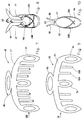
- Figures 1 and 2 show a first clamp according to the invention, designated under the general reference 10.
- This hair clip 10 has two monobloc jaws elongated, marked 11 and 12, connected by a return joint elastic shown schematically under reference 13.
- These jaws have two first longitudinal edges 11A and 12A respectively, as well as two other longitudinal edges 11B and 12B respectively.
- edges are not necessarily straight or even exactly parallel; this notion of edge longitudinal simply aims to designate the edges which extend substantially along the larger direction, at know the horizontal direction in figure 1.
- first longitudinal edges as well as the two other longitudinal edges, actually overlap so that the longitudinal edges 12A and 12B of the lower jaw, that is to say the one which, in figure 1, is masked by the other bit identified 11, do not appear in the drawing.
- Each of the other two longitudinal edges 11B and 12B is provided with a plurality of spaced apart teeth, substantially extending the jaws opposite the first longitudinal edges 11A and 12A, that is to say, in Figure 2, these teeth extend downward. These teeth are preferably curved and their concavities are facing the teeth of the plurality carried by the other jaw. These pluralities of teeth jointly form a succession longitudinal of pairs of teeth respectively forming part of each plurality of teeth. In the example shown in Figures 1 and 2, there are three pairs of support teeth 14, the teeth of each pair being substantially identical, so that the supporting teeth of the lower jaw 12 (the one which is not visible in FIG. 1) have the same profile as that of the upper jaw bearing teeth 11, visible in this figure 1.
- teeth 15A and 15B there are further four pairs of penetrating teeth such as teeth 15A and 15B, which are shorter and more curved, the 15A penetrating teeth of a first jaw crossing with the penetration teeth 15B of the second jaw when the clamp is closed.
- Figures 3 and 4 show a second conforming clamp to the invention, identified 20.
- this clamp 20 which correspond to elements of the clamp 10 of FIGS. 1 to 2 bear numbers of reference which are deduced from those mentioned above about Figures 1 and 2, increased by the number 10. This is for example that this clamp 20 comprises elongated monobloc jaws 21 and 22.
- This second clamp marked 20 is distinguished from clamp 10 by the curvature of the teeth and by the number of penetration teeth.
- These pairs of penetrating teeth are offset from each other along the longitudinal edges and extend perpendicular to the associated jaw further than the teeth of the pairs of support teeth in the direction of the other jaw, in sort of being able to cross paths.
- a tooth of 25A penetration shown in Figure 4 integral with the jaw right marked 21, at its end which goes further to the left as the end of the supporting tooth 24.
- Another way of characterize a pair of penetrating teeth is to say that these teeth are shorter than the supporting teeth but their curvature is greater than that of these support teeth.
- the pairs of teeth of penetration and support alternate. More specifically, the clamp 20 has three pairs of support teeth 24 (left, center and right) and two pairs of penetrating teeth 25A, 25B, located respectively between the pairs of support teeth on the left and in the center, and those located in the center and right.
- pairs of penetrating teeth 25A, 25B are substantially identical to each other; in addition, the teeth of each pair are substantially identical to each other.
- FIGS. 2 and 4 allow to understand the structure and function of the supporting teeth 14 and 24.
- the free end zones respective support teeth 14 and 24 remain apart from one the other, so that they remain in contact with the external surface of the hair or that they penetrate only in a limited manner the inside of the hair, thus remaining on or slightly below of the surface area of the hair.
- the pairs of penetration teeth 15A, 15B, 25A, 25B more curved penetrate in the hair by crossing.
- the clamps 10 and 20 allow a perfect hold satisfying of a wick in a hair.
- Figures 5 and 6 show a variant of realization of the clamp of figures 3 and 4.
- This clamp marked 30 as a whole, includes a certain elements of the same nature as those of FIGS. 3 and 4, and which are designated by reference numbers which are deduce from those referred to in these figures 3 and 4 by adding the number 10.
- this clamp 30 has two jaws elongated monoblocks 31 and 32.
- clamp 30 The difference between clamp 30 and clamp 20 is the number of pairs of support teeth 34, and penetrating teeth 35A / 35B.
- This clamp 30 includes, like the clamp 20, an alternation pairs of penetrating and supporting teeth, but these pliers 30 has five pairs of supporting teeth, alternating with four pairs penetration teeth.
- pliers can be defined according to the invention. If you want to keep the peculiarity of the pliers 20 and 30 that the extreme pairs of teeth are teeth support, while alternating the two types of teeth, we easily understands that in practice the number of these pairs of teeth support is odd, while the number of pairs of teeth penetration is an immediately lower number.
- FIGs 7 and 8 show yet another clamp according to the invention, identified 40 as a whole. She is a variant of the clamp 10 of Figures 1 and 2, and the elements of this clamp 40 which are similar to the elements of the clamp 10 are designated by reference numbers which are deduced from those used in these figures 1 and 2 by adding the number 30.
- This clamp 40 is distinguished from the clamp 10 of Figures 1 and 2 by the fact that the three pairs of bearing teeth 44, instead to be full and massive like the supporting teeth 14 in the example of Figures 1 and 2, are hollowed out, having here a form oval.
- FIGS 9 and 10 show yet another clamp according to the invention. This is identified under the reference general 50.
- clamps 20 and 50 The difference between clamps 20 and 50 is the causes the teeth which, in Figures 3 and 4, have a cross-section full and massive, as we can clearly see in Figure 3, are, in Figure 9, hollowed out, having as in Figure 7, a shape generally oval.
- FIGS 11 and 12 show yet another form for producing a clamp according to the invention.
- This clamp is identified under the general reference 60.
- the elements it comprises which are similar to elements of the clamp 20 of the Figures 3 and 4 are designated by reference numbers which are deduce from those used in these figures 3 and 4 by adding the number 40.
- this clip 60 includes elongated monoblock jaws 61 and 62.
- clamp 60 The difference between clamp 60 and clamp 20 is the fact that teeth, whether penetrating teeth or supporting teeth, have not a substantially curvature regular, visible in a figure such as Figure 4, but also have undulations, preferably also visible well in figure 11 than in figure 12.
- clamps are deduced from a possible combination of the characteristics of pliers 20 and 60, with par example, support teeth of massive section as in the pliers 20, and corrugated penetration teeth as in FIGS. 11 and 12. Similarly, the teeth may have undulations, either only parallel to the jaws, or only perpendicular to these.
- Figures 13 to 18 show a series, not limiting, of forms which it is possible to give to the teeth support, for example by modifying any of the clamps mentioned above.
- FIG. 13 represents a shaped support tooth generally rectangular hollowed out, connecting on a short side at the edge (shown schematically by a dotted line) of the jaw to which this tooth is fixed.
- FIG. 14 represents another bearing tooth having a triangular shape, connected to the associated jaw from one side. Well heard, alternatively, this tooth could be granted to the bit associated by the point.
- FIG. 15 represents a support tooth shaped as twist.
- FIG. 16 represents a support tooth shaped as substantially circular ring.
- FIG. 17 represents a support tooth whose shape is substantially that of a fork. It should be understood that, at Figures 13, 14 and 16, the shape of the teeth is that of a loop closed but we would get a fork shape as soon as we would remove an extreme part (so the lower part on the figures) of each of these teeth.
- Figure 18 shows yet another form of supporting teeth, namely that of a rhombus connected by a point at the edge of the associated jaw.
- the pairs of support teeth include two support teeth arranged face to face, having their free ends coming in look at each other.
- a space between the ends of the teeth pairs of bearing teeth can be kept by providing stop means 100 ( Figure 2) limiting the relative rotation of the jaws.
- the teeth of the pairs of supporting teeth can be offset laterally from each other.
- each of the jaws is, in a manner known per se, provided with support zones marked 16 in Figure 1, 26 in Figure 3 (and so on for the other pliers), areas used for easy operation for the installation of the clamp considered in a hair.
- the return joint elastic which connects the two jaws of each clamp can be located, not near the first longitudinal edges of the jaws, but with transverse edges of these jaws, for example with straight edges of each of these clips.
Landscapes
- Clamps And Clips (AREA)
- Brushes (AREA)
Abstract
Description
L'invention concerne une pince à cheveux du type comportant deux mors allongés reliés par une articulation à rappel élastique, que l'on peut mettre dans une chevelure pour en maintenir l'arrangement.The invention relates to a hair clip of the type with two elongated jaws connected by a return joint elastic, that you can put in a hair to maintain the arrangement.
Les mors comportent deux premiers bords longitudinaux respectifs, généralement reliés par l'articulation à rappel élastique, et deux autres bords longitudinaux respectifs munis chacun d'une pluralité de dents longitudinalement espacées.The jaws have two first longitudinal edges respective, generally connected by the return joint elastic, and two other respective longitudinal edges provided each of a plurality of longitudinally spaced teeth.
Dans certaines pinces, telles que décrites notamment dans le document US 5,549,127 A, ces dents espacées sont courbes, s'étendant sensiblement dans le prolongement des mors à l'opposé des premiers bords, et les dents d'un premier mors ayant leurs concavités tournées vers les dents de l'autre mors.In certain pliers, as described in particular in document US 5,549,127 A, these spaced teeth are curved, extending substantially in the extension of the jaws opposite of the first edges, and the teeth of a first bit having their concavities turned towards the teeth of the other jaw.
Pour assurer un bon maintien des cheveux, les dents des deux mors sont généralement conformées en sorte de pouvoir pénétrer et se croiser dans la chevelure, à proximité les unes des autres, et assurer ainsi un pincement des mèches de cheveux à maintenir.To ensure good hair retention, the teeth of two jaws are generally shaped so that they can penetrate and cross in the hair, close to each other, and thus ensure a pinching of the strands of hair to be maintained.
Les dents sont généralement proches les unes des autres, et leur nombre est en pratique assez important, de l'ordre d'au moins une demi-douzaine de dents sur chaque mors, ce qui constitue un nombre important de zones rapprochées de pincement. Or il est apparu qu'une zone de pincement est une zone en laquelle les cheveux sont fortement sollicités, au risque de se dégrader, et ce d'autant plus nettement que les zones de pincement adjacentes sont proches.The teeth are usually close to each other, and their number is in practice quite significant, of the order of at least minus half a dozen teeth on each jaw, which constitutes a large number of close toe-in areas. But, he is appeared that a pinch zone is a zone in which the hair is under heavy stress, at the risk of deterioration, and all the more clearly as the adjacent pinch zones are relatives.
En outre, un bon maintien dans la chevelure nécessite des dents relativement fines qui pénètrent dans la chevelure sans la déformer sensiblement. Il en résulte que les cheveux au voisinage de la pince ne sont pas sensiblement déplacés, et l'effet esthétique de la pince se limite à la zone qu'elle occupe.In addition, good support in the hair requires relatively fine teeth that penetrate the hair without the distort noticeably. As a result, the hair in the vicinity of the clamp are not noticeably displaced, and the effect aesthetics of the forceps is limited to the area it occupies.
On connaít également des pinces de maintien de boucles de cheveux pendant une mise en pli, décrites dans le document FR 557 331 A ou dans le document FR 934 493 A. Les dents sont allongées et peu incurvées, en regard les unes des autres, et ne permettent pas une tenue permanente efficace dans la chevelure.We also know clamps holding loops hair during styling, described in the document FR 557 331 A or in document FR 934 493 A. The teeth are elongated and slightly curved, facing each other, and do not not allow an effective permanent hold in the hair.
Le document US 1,819,667 A décrit un dispositif pour onduler les cheveux, comprenant deux mors dentés ayant chacun un élément secondaire denté déplaçable longitudinalement pour forcer l'ondulation des cheveux. Les dents des éléments secondaires sont divergentes et peu incurvées, et le dispositif n'est pas adapté pour une tenue permanente efficace dans la chevelure.Document US 1,819,667 A describes a device for waving the hair, comprising two toothed jaws each having a toothed secondary element movable longitudinally to force waving hair. The teeth of the secondary elements are divergent and slightly curved, and the device is not adapted for an effective permanent hold in the hair.
L'invention a pour objet de pallier les inconvénients des pinces connues, en permettant un bon maintien permanent de mèches de cheveux par une pince minimisant les sollicitations de pincement risquant de casser les cheveux, tout en produisant avantageusement un effet esthétique plus étendu.The object of the invention is to overcome the drawbacks of known pliers, allowing good permanent hold of wicks of hair by pliers minimizing pinching stresses risking breaking the hair, while producing advantageously a more extensive aesthetic effect.
L'invention propose à cet effet une pince à cheveux comportant deux mors monoblocs allongés reliés par une articulation à rappel élastique et limités par deux premiers bords longitudinaux respectifs et par deux autres bords longitudinaux respectifs, les deux autres bords longitudinaux respectifs étant chacun munis d'une pluralité de dents de pénétration courbes espacées prolongeant sensiblement les mors à l'opposé des premiers bords et dont les concavités sont tournées vers les dents de l'autre mors pour pénétrer dans la chevelure, ces pluralités de dents de pénétration formant conjointement une succession longitudinale de paires de dents faisant respectivement partie de chaque pluralité de dents, cette succession longitudinale de paires de dents comportant en outre au moins une paire de dents d'appui dont les zones d'extrémités sont disposées et orientées pour venir en appui sur ou peu en dessous de la zone de surface de la chevelure.The invention provides for this purpose a hair clip comprising two elongated monobloc jaws connected by a joint with elastic return and limited by two first longitudinal edges respective and by two other respective longitudinal edges, the two other respective longitudinal edges each being provided with a plurality of spaced curved penetration teeth extending substantially the jaws opposite the first edges and whose concavities are turned towards the teeth of the other jaw to penetrate the hair, these pluralities of penetrating teeth jointly forming a longitudinal succession of pairs of teeth respectively forming part of each plurality of teeth, this longitudinal succession of pairs of teeth comprising in in addition to at least one pair of support teeth whose zones ends are arranged and oriented to bear on or slightly below the surface area of the hair.
L'invention découle notamment de la constatation que, pour maintenir efficacement des mèches de cheveux, il n'est pas nécessaire, contrairement à ce que l'on pourrait penser, de provoquer un pincement important des cheveux (de préférence en de multiples endroits rapprochés) par des dents de pénétration pour les maintenir efficacement, dès lors que la pince comprend d'autres moyens assurant le maintien de son orientation par rapport à la chevelure.The invention derives in particular from the observation that, for maintain strands of hair effectively, it is not necessary, contrary to what one might think, to cause significant pinching of the hair (preferably in multiple places close together) by penetrating teeth for maintain them effectively, as long as the clamp includes other means ensuring the maintenance of its orientation relative to the hair.
En conséquence, il peut suffire de prévoir en outre, sur les mors, des dents d'appui incurvées dont les zones d'extrémités viennent en appui sur la chevelure pour obtenir un maintien satisfaisant de l'orientation de la pince par rapport à une chevelure : puisque ces dents d'appui sont décalées le long de la direction longitudinale des mors, elles assurent un maintien de l'orientation de la pince, et le serrage des mèches de cheveux peut suffire. En outre, il est apparu que ces dents d'appui, outre qu'elles assurent le maintien de l'orientation de la pince dans les cheveux, génèrent dans la chevelure des ondulations d'apparence agréable autour de la zone occupée par la pince. A ce premier effet esthétique s'ajoute le fait que les dents d'appui, qui s'enfoncent moins dans la chevelure que les dents de pénétration connues précitées, peuvent être plus larges que celles-ci (cela renforce l'effet de maintien assuré par la pince), et peuvent ainsi, si on le souhaite, être aisément visibles dans la chevelure et assurer ainsi un effet de parure de la chevelure qui s'ajoute à l'effet de maintien.Consequently, it may suffice to provide further, on the jaws, curved support teeth whose end zones come to rest on the hair to obtain support satisfactory the orientation of the clamp relative to a hair: since these supporting teeth are offset along the longitudinal direction of the jaws, they maintain the orientation of the clamp, and the tightening of the locks of hair can suffice. In addition, it appeared that these supporting teeth, in addition to that they maintain the orientation of the clamp in the hair, generate appearance ripples in the hair pleasant around the area occupied by the clamp. To this first effect aesthetic is added the fact that the supporting teeth, which sink less in the hair than the known penetrating teeth mentioned above, may be wider than these (this reinforces the holding effect provided by the clamp), and can thus, if wish to be easily visible in the hair and ensure thus an effect of adornment of the hair which is added to the effect of maintenance.
Ladite succession longitudinale de paires de dents comporte au moins une paire de dents de pénétration qui sont décalées l'une de l'autre le long desdits autres bords longitudinaux des mors et qui s'étendent perpendiculairement au mors associé plus loin que les dents d'appui en direction de l'autre mors, en sorte de pouvoir se croiser. Ainsi, la présence de telles dents de pénétration, assurant un pincement comme dans les pinces connues considérées ci-dessus, est avantageuse car elle assure, avec les dents d'appui, un maintien optimum sans toutefois provoquer de sollicitations trop violentes des cheveux ; cela est d'autant plus vrai que les dents de pénétration n'ont pas besoin d'être trop proches, et peuvent avantageusement être séparées les unes des autres par une paire de dents d'appui (voir ci-dessous).Said longitudinal succession of pairs of teeth has at least one pair of penetrating teeth which are offset from each other along said other edges longitudinal of the jaws and which extend perpendicular to the associated bit further than the supporting teeth in the direction of the other bit, so that you can cross. So the presence of such penetration teeth, ensuring pinching as in known pliers considered above, is advantageous because it ensures, with the support teeth, optimum support without, however cause too violent stresses on the hair; that is especially since the penetration teeth do not need to be too close, and can advantageously be separated the from each other by a pair of supporting teeth (see below).
De manière également préférée, ladite succession longitudinale de paires de dents comporte au moins une paire de dents de pénétration qui sont plus courtes que les dents d'appui, et dont la courbure est plus importante que celle de ces dents d'appui. Ainsi la présence de deux types de dents permet d'assurer un maintien dans la chevelure selon des sollicitations différentes, sur des mèches différentes, ce qui évite de trop solliciter une même mèche de cheveux.Also preferably, said succession longitudinal pair of teeth has at least one pair of penetration teeth which are shorter than the supporting teeth, and whose curvature is greater than that of these teeth support. Thus the presence of two types of teeth ensures maintenance in the hair according to different stresses, on different wicks, which avoids overloading a same lock of hair.
Dans les deux cas précités, on comprend aisément qu'il est avantageux que les paires de dents d'appui et les paires de dents de pénétration alternent au sein de la succession longitudinale de paires de dents, en sorte d'assurer un bon espacement entre les paires de dents sollicitant une même mèche de cheveux de la même manière.In the two aforementioned cases, it is easily understood that it is advantageous that pairs of supporting teeth and pairs of teeth of penetration alternate within the longitudinal succession of pairs of teeth, so as to ensure good spacing between the pairs of teeth using the same lock of hair from the same way.
Préférentiellement, au moins les paires de dents situées aux extrémités de la succession longitudinale de paires de dents sont des dents d'appui, ce qui renforce le maintien en orientation de la pince par les dents d'appui. Lorsque les dents de pénétration et d'appui alternent (voir ci-dessus) cela conduit à un nombre de dents de pénétration (susceptibles de solliciter fortement les mèches de cheveux) inférieur à celui des dents d'appui.Preferably, at least the pairs of teeth located at the ends of the longitudinal succession of pairs of teeth are supporting teeth, which reinforces the maintenance in orientation of the clamp by the supporting teeth. When the penetration teeth and support alternate (see above) this leads to a number of penetration teeth (likely to place heavy stress on strands of hair) lower than that of the supporting teeth.
Les dents de pénétration peuvent être simplement courbées, mais peuvent aussi être ondulées, présentant par exemple des ondulations parallèles aux mors, ce qui conforte leur effet de maintien dans la chevelure.The penetration teeth can be simply bent, but can also be wavy, for example with undulations parallel to the jaws, which reinforces their effect of maintenance in the hair.
Quant aux dents d'appui, il a été mentionné ci-dessus qu'elles sont avantageusement plus larges que les dents de pénétration. De manière générale, les dents d'appui ont avantageusement une section massive (c'est-à-dire qu'elles ne sont pas effilées sur toute leur longueur), ce qui (voir ci-dessus) favorise un bon maintien dans la chevelure. Dans une première forme de réalisation tout à fait simple, qui permet notamment de rendre la pince bien visible dans la chevelure (lorsqu'il est souhaité faire jouer à la pince un rôle de parure), les dents d'appui sont pleines. Toutefois, dans une forme de réalisation intéressante, ces dents d'appui sont évidées, ayant la forme d'une boucle fermée, ou celle d'une fourche. On comprend aisément qu'une forme fourchue renforce l'effet de maintien. Quant à la forme de boucle fermée, elle peut être circulaire, ovale, polygonale (triangulaire, rectangulaire, etc.). Par analogie avec ce qui est indiqué ci-dessus à propos des dents de pénétration, les dents d'appui peuvent être elles-mêmes ondulées pour renforcer l'effet d'ondulation induit dans la chevelure. Elles peuvent avoir bien d'autres formes, par exemple celle d'une torsade ou d'une tresse, avec éventuellement les mêmes effets.As for the supporting teeth, it was mentioned above that they are advantageously wider than the teeth of penetration. Generally, the supporting teeth have advantageously a massive section (that is to say that they are not not tapered over their entire length), which (see above) promotes good support in the hair. In a first form very simple implementation, which allows in particular to make the clip clearly visible in the hair (when desired make the pliers play a role of adornment), the supporting teeth are full. However, in an interesting embodiment, these supporting teeth are hollowed out, in the form of a closed loop, or that of a fork. It is easy to understand that a forked shape strengthens the holding effect. As for the closed loop shape, it can be circular, oval, polygonal (triangular, rectangular, etc.). By analogy with what is indicated above about penetrating teeth, the supporting teeth can themselves be wavy to enhance the wavy effect induced in the hair. They can have many other forms, for example that of a twist or a braid, with possibly the same effects.
L'articulation à rappel élastique reliant les deux mors est avantageusement située sur les premiers bords longitudinaux des mors (donc transversalement à l'opposé des bords longitudinaux munis de dents). L'invention s'applique toutefois aussi à une pince dont les mors sont reliés par des bords transversaux. En fonction de l'emplacement de cette articulation à rappel élastique, des zones d'appui sont avantageusement ménagées sur les mors en sorte de permettre la manoeuvre des mors à l'encontre dudit rappel élastique pour permettre la pose de la pince dans la chevelure.The elastic return joint connecting the two jaws is advantageously located on the first longitudinal edges of the jaw (therefore transversely opposite to the longitudinal edges with teeth). The invention however also applies to pliers the jaws of which are connected by transverse edges. Depending the location of this elastic return joint, support zones are advantageously provided on the jaws so to allow the operation of the jaws against said recall elastic to allow the installation of the clamp in the hair.
Des objets, caractéristiques et avantages de l'invention ressortent de la description qui suit, donnée à titre d'exemple illustratif non limitatif, en regard des dessins annexés sur lesquels :
- la figure 1 est une vue de dessus d'une première pince conforme à l'invention,
- la figure 2 est une vue en bout, selon la flèche II de la figure 1,
- la figure 3 est une vue de dessus d'une seconde pince conforme à l'invention,
- la figure 4 en est une vue en bout, selon la flèche IV de la figure 3,
- la figure 5 est une vue de dessus d'une variante de la pince des figures 3 et 4,
- la figure 6 en est une vue en bout, selon la flèche VI de la figure 5,
- la figure 7 est une vue de dessus d'une troisième pince conforme à l'invention,
- la figure 8 en est une vue en bout selon la flèche VIII de la figure 7,
- la figure 9 est une vue de dessus d'une quatrième pince conforme à l'invention, comportant des dents de deux types différents, dont des dents évidées,
- la figure 10 en est une vue en bout selon la flèche X de la figure 9,
- la figure 11 est une vue de dessus d'une cinquième pince conforme à l'invention, comportant des dents de deux types, ces dents étant ondulées,
- la figure 12 en est une vue en bout selon la flèche XII de la figure 11,
- la figure 13 est une vue de détail montrant une dent d'appui, de forme rectangulaire évidée,
- la figure 14 est une vue de détail représentant une autre dent d'appui ayant la forme d'un triangle évidé,
- la figure 15 est une vue de détail représentant une autre dent d'appui ayant la forme de torsade,
- la figure 16 est une vue de détail montrant une dent d'appui de forme annulaire,
- la figure 17 est une vue de détail montrant une dent d'appui en forme de fourche, et,
- la figure 18 est une vue de détail montrant une dent d'appui dont la forme est celle d'un losange évidé.
- FIG. 1 is a top view of a first clamp according to the invention,
- FIG. 2 is an end view, according to arrow II in FIG. 1,
- FIG. 3 is a top view of a second clamp according to the invention,
- FIG. 4 is an end view thereof, according to arrow IV of FIG. 3,
- FIG. 5 is a top view of a variant of the clamp of FIGS. 3 and 4,
- FIG. 6 is an end view thereof, along arrow VI of FIG. 5,
- FIG. 7 is a top view of a third clamp according to the invention,
- FIG. 8 is an end view thereof according to arrow VIII of FIG. 7,
- FIG. 9 is a top view of a fourth clamp according to the invention, comprising teeth of two different types, including hollowed teeth,
- FIG. 10 is an end view thereof according to arrow X in FIG. 9,
- FIG. 11 is a top view of a fifth clamp according to the invention, comprising teeth of two types, these teeth being wavy,
- FIG. 12 is an end view thereof according to arrow XII of FIG. 11,
- FIG. 13 is a detail view showing a supporting tooth, of hollowed-out rectangular shape,
- FIG. 14 is a detail view showing another support tooth having the shape of a hollow triangle,
- FIG. 15 is a detail view showing another support tooth having the shape of a twist,
- FIG. 16 is a detail view showing an annular support tooth,
- FIG. 17 is a detail view showing a fork-shaped bearing tooth, and,
- Figure 18 is a detail view showing a support tooth whose shape is that of a hollow diamond.
Les figures 1 et 2 représentent une première pince
conforme à l'invention, désignée sous la référence générale 10.Figures 1 and 2 show a first clamp
according to the invention, designated under the
Cette pince à cheveux 10 comporte deux mors monoblocs
allongés, repérés 11 et 12, reliés par une articulation à rappel
élastique schématisée sous la référence 13.This
Ces mors comportent deux premiers bords longitudinaux
respectifs 11A et 12A, ainsi que deux autres bords longitudinaux
respectifs 11B et 12B.These jaws have two first
Ces bords longitudinaux ne sont pas nécessairement rectilignes ni même exactement parallèles ; cette notion de bord longitudinal vise simplement à désigner les bords qui s'étendent sensiblement le long de la direction de plus grande dimension, à savoir la direction horizontale dans la figure 1.These longitudinal edges are not necessarily straight or even exactly parallel; this notion of edge longitudinal simply aims to designate the edges which extend substantially along the larger direction, at know the horizontal direction in figure 1.
En fait, les premiers bords longitudinaux, ainsi que les deux autres bords longitudinaux, se superposent en réalité de sorte que les bords longitudinaux 12A et 12B du mors inférieur, c'est-à-dire celui qui, à la figure 1, est masqué par l'autre mors repéré 11, n'apparaissent pas sur le dessin.In fact, the first longitudinal edges, as well as the two other longitudinal edges, actually overlap so that the longitudinal edges 12A and 12B of the lower jaw, that is to say the one which, in figure 1, is masked by the other bit identified 11, do not appear in the drawing.
Chacun des deux autres bords longitudinaux 11B et 12B est
muni d'une pluralité de dents espacées, prolongeant sensiblement
les mors à l'opposé des premiers bords longitudinaux 11A et 12A,
c'est-à-dire que, à la figure 2, ces dents s'étendent vers le bas.
Ces dents sont de préférence courbes et leurs concavités sont
tournées vers les dents de la pluralité portée par l'autre mors.
Ces pluralités de dents forment conjointement une succession
longitudinale de paires de dents faisant respectivement partie de
chaque pluralité de dents. Dans l'exemple représenté aux figures 1
et 2, il y a trois paires de dents d'appui 14, les dents de chaque
paire étant sensiblement identiques, de sorte que les dents d'appui
du mors inférieur 12 (celui qui n'est pas visible à la figure 1)
ont le même profil que celui des dents d'appui du mors supérieur
11, visible sur cette figure 1.Each of the other two longitudinal edges 11B and 12B is
provided with a plurality of spaced apart teeth, substantially extending
the jaws opposite the first
Cette succession de trois paires de dents d'appui 14,
sensiblement identiques au sein de chaque paire, mais aussi
sensiblement identiques d'une paire à la suivante, ont leurs
extrémités 14A qui sont disposées à l'écart l'une de l'autre. On
observe en effet à la figure 2 que les extrémités inférieures des
dents restent à l'écart l'une de l'autre lorsque la pince est
fermée.This succession of three pairs of
Dans l'exemple des figures 1 et 2, il y a en outre quatre
paires de dents de pénétration telles que les dents 15A et 15B, qui
sont plus courtes et plus incurvées, les dents de pénétration 15A
d'un premier mors se croisant avec les dents de pénétration 15B du
second mors lorsque la pince est fermée.In the example of Figures 1 and 2, there are further four
pairs of penetrating teeth such as
Les figures 3 et 4 représentent une seconde pince conforme à l'invention, repérée 20.Figures 3 and 4 show a second conforming clamp to the invention, identified 20.
Les éléments de cette pince 20 qui correspondent à des
éléments de la pince 10 des figures 1 à 2 portent des numéros de
référence qui se déduisent de ceux mentionnés ci-dessus à propos
des figures 1 et 2, augmentés du nombre 10. C'est ainsi par exemple
que cette pince 20 comporte des mors monoblocs allongés 21 et 22.The elements of this
Cette seconde pince repérée 20 se distingue de la pince 10
par la courbure des dents et par le nombre de dents de pénétration.
On retrouve deux paires de dents de pénétration respectivement
repérées 25A et 25B. Ces paires de dents de pénétration sont
décalées l'une de l'autre le long des bords longitudinaux et
s'étendent perpendiculairement au mors associé plus loin que les
dents des paires de dents d'appui en direction de l'autre mors, en
sorte de pouvoir se croiser. C'est ainsi par exemple qu'une dent de
pénétration 25A représentée sur la figure 4, solidaire du mors de
droite repéré 21, a son extrémité qui va plus loin vers la gauche
que l'extrémité de la dent d'appui 24. Une autre manière de
caractériser une paire de dents de pénétration est de dire que ces
dents sont plus courtes que les dents d'appui mais que leur
courbure est plus importante que celle de ces dents d'appui.This second clamp marked 20 is distinguished from
Dans l'exemple représenté, les paires de dents de
pénétration et d'appui alternent. Plus précisément, la pince 20
comporte trois paires de dents d'appui 24 (à gauche, au centre et à
droite) et deux paires de dents de pénétration 25A, 25B, situées
respectivement entre les paires de dents d'appui situées à gauche
et au centre, et celles situées au centre et à droite.In the example shown, the pairs of teeth of
penetration and support alternate. More specifically, the
Ces paires de dents de pénétration 25A, 25B sont
sensiblement identiques l'une à l'autre ; en outre, les dents de
chaque paire sont sensiblement identiques l'une à l'autre.These pairs of penetrating
Les figures, notamment les figures 2 et 4, permettent de
comprendre la structure et le fonctionnement des dents d'appui 14
et 24. En position fermée de la pince, les zones d'extrémité libre
des dents d'appui respectives 14 et 24 restent à l'écart l'une de
l'autre, de sorte qu'elles restent en appui sur la surface externe
de la chevelure ou qu'elles ne pénètrent que de façon limitée à
l'intérieur de la chevelure, en restant ainsi sur ou peu en dessous
de la zone de surface de la chevelure. A contrario, les paires de
dents de pénétration 15A, 15B, 25A, 25B plus incurvées pénètrent
dans la chevelure en se croisant.The figures, in particular Figures 2 and 4, allow to
understand the structure and function of the supporting
Les pinces 10 et 20 permettent un maintien tout à fait
satisfaisant d'une mèche dans une chevelure.The
Les figures 5 et 6 représentent une variante de réalisation de la pince des figures 3 et 4.Figures 5 and 6 show a variant of realization of the clamp of figures 3 and 4.
Cette pince, repérée 30 dans son ensemble, comporte un
certain nombre d'éléments de même nature que ceux des figures 3 et
4, et qui sont désignés par des numéros de référence qui se
déduisent de ceux visés sur ces figures 3 et 4 par addition du
nombre 10.This clamp, marked 30 as a whole, includes a
certain elements of the same nature as those of FIGS. 3 and
4, and which are designated by reference numbers which are
deduce from those referred to in these figures 3 and 4 by adding the
C'est ainsi que cette pince 30 comporte deux mors
monoblocs allongés 31 et 32.This is how this
La différence entre la pince 30 et la pince 20 réside dans
le nombre de paires de dents d'appui 34, et de dents de pénétration
35A/35B. Cette pince 30 comporte, comme la pince 20, une alternance
de paires de dents de pénétration et d'appui, mais cette pince 30
comporte cinq paires de dents d'appui, alternant avec quatre paires
de dents de pénétration.The difference between
D'autres types de pinces peuvent être définis selon
l'invention. Si on souhaite conserver la particularité des pinces
20 et 30 selon laquelle les paires de dents extrêmes sont des dents
d'appui, tout en faisant alterner les deux types de dents, on
comprend aisément qu'en pratique le nombre de ces paires de dents
d'appui est impair, tandis que le nombre de paires de dents de
pénétration est un nombre immédiatement inférieur.Other types of pliers can be defined according to
the invention. If you want to keep the peculiarity of the
Les figures 7 et 8 représentent encore une autre pince
conforme à l'invention, repérée 40 dans son ensemble. Elle est une
variante de la pince 10 des figures 1 et 2, et les éléments de
cette pince 40 qui sont similaires aux éléments de la pince 10 sont
désignés par des numéros de référence qui se déduisent de ceux
utilisés sur ces figures 1 et 2 par addition du nombre 30.Figures 7 and 8 show yet another clamp
according to the invention, identified 40 as a whole. She is a
variant of the
Cette pince 40 se distingue de la pince 10 des figures 1
et 2 par le fait que les trois paires de dents d'appui 44, au lieu
d'être pleines et massives comme les dents d'appui 14 dans
l'exemple des figures 1 et 2, sont évidées, ayant ici une forme
ovale.This
Bien entendu, cet évidemment des dents étant réalisé
perpendiculairement au plan des figures 1 et 7, les figures 2 et 8,
qui représentent les pinces 10 et 40, vues de bout, sont
identiques.Of course, this obviously teeth being made
perpendicular to the plane of Figures 1 and 7, Figures 2 and 8,
which represent the
Les figures 9 et 10 représentent encore une autre pince conforme à l'invention. Celle-ci est repérée sous la référence générale 50.Figures 9 and 10 show yet another clamp according to the invention. This is identified under the reference general 50.
Elle est tout à fait similaire à la pince 20 des figures 3
et 4. Les éléments de ces figures 9 et 10 qui se retrouvent dans
les figures 3 et 4, sont désignés par des numéros de référence qui
se déduisent de ceux utilisés sur ces figures 3 et 4 par addition
du nombre 30. C'est ainsi notamment que la pince 50 comporte des
mors monoblocs allongés 51 et 52.It is quite similar to the
La différence entre les pinces 20 et 50 réside dans le
fait que les dents qui, dans les figures 3 et 4, ont une section
pleine et massive, ainsi qu'on le voit clairement sur la figure 3,
sont, à la figure 9, évidées, ayant comme à la figure 7, une forme
globalement ovale.The difference between
Les figures 4 et 10 se révèlent identiques puisque la modification de dents du premier type n'apparaít pas en vue transversale.Figures 4 and 10 turn out to be identical since the modification of teeth of the first type does not appear in sight transverse.
Les figures 11 et 12 représentent encore une autre forme
de réalisation d'une pince selon l'invention. Cette pince est
repérée sous la référence générale 60. Les éléments qu'elle
comporte qui sont similaires à des éléments de la pince 20 des
figures 3 et 4 sont désignés par des numéros de référence qui se
déduisent de ceux utilisés dans ces figures 3 et 4 par addition du
nombre 40. C'est ainsi par exemple que cette pince 60 comporte des
mors monoblocs allongés 61 et 62.Figures 11 and 12 show yet another form
for producing a clamp according to the invention. This clamp is
identified under the
La différence entre la pince 60 et la pince 20 réside dans
le fait que les dents, qu'il s'agisse des dents de pénétration ou
des dents d'appui, ont, non pas une courbure sensiblement
régulière, visible sur une figure telle que la figure 4, mais
comportent en outre des ondulations, visibles de préférence aussi
bien sur la figure 11 que sur la figure 12.The difference between
Bien entendu, d'autres pinces se déduisent d'une possible
combinaison des caractéristiques des pinces 20 et 60, avec par
exemple, des dents d'appui de section massive comme dans la pince
20, et des dents de pénétration ondulées comme aux figures 11 et
12. De même, les dents peuvent présenter des ondulations, soit
uniquement parallèlement aux mors, soit uniquement
perpendiculairement à ceux-ci.Of course, other clamps are deduced from a possible
combination of the characteristics of
Les figures 13 à 18 représentent une série, non limitative, de formes qu'il est possible de donner aux dents d'appui, en modifiant par exemple l'une quelconque des pinces précitées.Figures 13 to 18 show a series, not limiting, of forms which it is possible to give to the teeth support, for example by modifying any of the clamps mentioned above.
La figure 13 représente une dent d'appui de forme généralement rectangulaire évidée, se raccordant par un petit côté au bord (schématisé par une ligne en pointillé) du mors auquel cette dent est fixée.FIG. 13 represents a shaped support tooth generally rectangular hollowed out, connecting on a short side at the edge (shown schematically by a dotted line) of the jaw to which this tooth is fixed.
La figure 14 représente une autre dent d'appui ayant une forme triangulaire, raccordée au mors associé par un côté. Bien entendu, en variante, cette dent pourrait être accordée au mors associé par la pointe.FIG. 14 represents another bearing tooth having a triangular shape, connected to the associated jaw from one side. Well heard, alternatively, this tooth could be granted to the bit associated by the point.
La figure 15 représente une dent d'appui conformée en torsade.FIG. 15 represents a support tooth shaped as twist.
La figure 16 représente une dent d'appui conformée en anneau sensiblement circulaire.FIG. 16 represents a support tooth shaped as substantially circular ring.
La figure 17 représente une dent d'appui dont la forme est sensiblement celle d'une fourche. Il faut bien comprendre que, aux figures 13, 14 et 16, la forme des dents est celle d'une boucle fermée mais qu'on obtiendrait une forme de fourche dès lors qu'on enlèverait une partie extrême (donc la partie inférieure sur les figures) de chacune de ces dents.FIG. 17 represents a support tooth whose shape is substantially that of a fork. It should be understood that, at Figures 13, 14 and 16, the shape of the teeth is that of a loop closed but we would get a fork shape as soon as we would remove an extreme part (so the lower part on the figures) of each of these teeth.
Enfin, la figure 18 représente encore une autre forme de dents d'appui, à savoir celle d'un losange raccordé par une pointe au bord du mors associé.Finally, Figure 18 shows yet another form of supporting teeth, namely that of a rhombus connected by a point at the edge of the associated jaw.
On peut noter que, de manière générale, toutes les dents de pénétration qui ont été représentées dans les dessins sont beaucoup plus fines et effilées que les dents d'appui, qu'il s'agisse de celles des figures 1, 3, 5, 11, ou celles des figures 7 et 9.It can be noted that, in general, all the teeth of penetration which have been shown in the drawings are much thinner and tapered than the supporting teeth, which it are those of Figures 1, 3, 5, 11, or those of Figures 7 and 9.
Il faut noter que les notions de sections massives ou effilées que l'on peut utiliser pour distinguer les dents d'appui et de pénétration ne s'analysent qu'en vue de dessus étant précisé que, ainsi que cela ressort des figures en bout, les diverses dents ont avantageusement la même épaisseur.It should be noted that the notions of massive sections or that can be used to distinguish the supporting teeth and penetration are only analyzed when viewed from above being specified that, as can be seen from the end figures, the various teeth advantageously have the same thickness.
Dans les modes de réalisation illustrés sur les figures, les paires de dents d'appui comprennent deux dents d'appui disposées face à face, ayant leurs extrémités libres venant en regard l'une de l'autre. En position fermée de la pince, un espace entre les extrémités des dents des paires de dents d'appui peut être conservé en prévoyant des moyens de butées 100 (figure 2) limitant la rotation relative des mors.In the embodiments illustrated in the figures, the pairs of support teeth include two support teeth arranged face to face, having their free ends coming in look at each other. In the closed position of the clamp, a space between the ends of the teeth pairs of bearing teeth can be kept by providing stop means 100 (Figure 2) limiting the relative rotation of the jaws.
En alternative, les dents des paires de dents d'appui peuvent être décalées latéralement l'une de l'autre.Alternatively, the teeth of the pairs of supporting teeth can be offset laterally from each other.
Par ailleurs, chacun des mors est, de façon connue en soi, muni de zones d'appui repérées 16 à la figure 1, 26 à la figure 3 (et ainsi de suite pour les autres pinces), zones servant à une manoeuvre aisée pour la pose de la pince considérée dans une chevelure.Furthermore, each of the jaws is, in a manner known per se, provided with support zones marked 16 in Figure 1, 26 in Figure 3 (and so on for the other pliers), areas used for easy operation for the installation of the clamp considered in a hair.
En variante non représentée, l'articulation à rappel élastique qui relie les deux mors de chaque pince peut se situer, non pas à proximité des premiers bords longitudinaux des mors, mais auprès de bords transversaux de ces mors, par exemple auprès des bords droits de chacune de ces pinces.In a variant not shown, the return joint elastic which connects the two jaws of each clamp can be located, not near the first longitudinal edges of the jaws, but with transverse edges of these jaws, for example with straight edges of each of these clips.
Claims (12)
Applications Claiming Priority (2)
| Application Number | Priority Date | Filing Date | Title |
|---|---|---|---|
| FR9901033A FR2788950B1 (en) | 1999-01-29 | 1999-01-29 | MATCHING TOOTH HAIR CLIP |
| FR9901033 | 1999-01-29 |
Publications (2)
| Publication Number | Publication Date |
|---|---|
| EP1023853A1 true EP1023853A1 (en) | 2000-08-02 |
| EP1023853B1 EP1023853B1 (en) | 2004-06-16 |
Family
ID=9541386
Family Applications (1)
| Application Number | Title | Priority Date | Filing Date |
|---|---|---|---|
| EP00420015A Expired - Lifetime EP1023853B1 (en) | 1999-01-29 | 2000-01-24 | Hair clip with matched teeth |
Country Status (4)
| Country | Link |
|---|---|
| US (1) | US6189544B1 (en) |
| EP (1) | EP1023853B1 (en) |
| CA (1) | CA2296981C (en) |
| FR (1) | FR2788950B1 (en) |
Cited By (2)
| Publication number | Priority date | Publication date | Assignee | Title |
|---|---|---|---|---|
| FR2900315A1 (en) * | 2006-04-28 | 2007-11-02 | Jean Francois Potut | LOCKING CLAMP. |
| FR2900314A1 (en) * | 2006-04-28 | 2007-11-02 | Jean Francois Potut | Hair clip, has elastic return unit permanently returning jaws into open position, and locking unit constituted of elastic rods and selectively locking jaws in closed position by directly exerting locking action on jaw bodies |
Families Citing this family (7)
| Publication number | Priority date | Publication date | Assignee | Title |
|---|---|---|---|---|
| FR2814347B1 (en) * | 2000-09-26 | 2002-12-06 | C S P Diffusion Sa | LIGHT JAW HAIR CLIP |
| US20030101285A1 (en) * | 2001-11-28 | 2003-05-29 | Yi-Tun Huang | Control interface card adapted for auto-reloading object position data, comparing object position data, and providing a triggering signal |
| US20040231691A1 (en) * | 2003-05-19 | 2004-11-25 | Shyu Shyh Ming | Hair clip having spring shielding device |
| US20050016560A1 (en) * | 2003-07-21 | 2005-01-27 | Dee Voughlohn | Unique hair-styling system and method |
| US8327860B2 (en) * | 2007-03-27 | 2012-12-11 | Linda Flowers | Heat retaining hair curling system and method of styling |
| US8528573B2 (en) * | 2010-08-31 | 2013-09-10 | Goody Products Inc. | Resilient claw hair clip |
| US10178904B2 (en) * | 2016-03-15 | 2019-01-15 | Sheena Scavone | Hair clip for increasing hair volume and curl lift |
Citations (4)
| Publication number | Priority date | Publication date | Assignee | Title |
|---|---|---|---|---|
| FR557331A (en) | 1922-10-11 | 1923-08-07 | Hair waving pliers | |
| US1819667A (en) | 1929-06-25 | 1931-08-18 | Aaronson Andre | Hairdressing device |
| FR934493A (en) | 1946-10-12 | 1948-05-24 | Perma Sa | Method and devices for curling hair |
| US5549127A (en) | 1995-05-03 | 1996-08-27 | Chang; Wen-Hsiung | Spring fixing structure for a hairgrip |
Family Cites Families (7)
| Publication number | Priority date | Publication date | Assignee | Title |
|---|---|---|---|---|
| US1042940A (en) * | 1912-01-25 | 1912-10-29 | John H Mcconnell | Mustache-guard. |
| US2049773A (en) * | 1935-07-16 | 1936-08-04 | Arthur M Herschensohn | Hair waving device |
| US2083761A (en) * | 1936-05-09 | 1937-06-15 | Tresenberg Paul | Hair waving device |
| US2171503A (en) * | 1939-01-26 | 1939-08-29 | Delamere Co Inc | Wave forming and setting device |
| US2712319A (en) * | 1954-03-11 | 1955-07-05 | Roitner Leo | Hair waver |
| FR2746608B1 (en) * | 1996-03-29 | 1998-05-15 | Robert Revais Soc | HAIR CLIP |
| JP3121285B2 (en) * | 1997-04-07 | 2000-12-25 | 株式会社ヤスダコーポレーション | Hair stopper |
-
1999
- 1999-01-29 FR FR9901033A patent/FR2788950B1/en not_active Expired - Fee Related
-
2000
- 2000-01-24 EP EP00420015A patent/EP1023853B1/en not_active Expired - Lifetime
- 2000-01-25 CA CA002296981A patent/CA2296981C/en not_active Expired - Fee Related
- 2000-01-28 US US09/493,460 patent/US6189544B1/en not_active Expired - Fee Related
Patent Citations (4)
| Publication number | Priority date | Publication date | Assignee | Title |
|---|---|---|---|---|
| FR557331A (en) | 1922-10-11 | 1923-08-07 | Hair waving pliers | |
| US1819667A (en) | 1929-06-25 | 1931-08-18 | Aaronson Andre | Hairdressing device |
| FR934493A (en) | 1946-10-12 | 1948-05-24 | Perma Sa | Method and devices for curling hair |
| US5549127A (en) | 1995-05-03 | 1996-08-27 | Chang; Wen-Hsiung | Spring fixing structure for a hairgrip |
Cited By (5)
| Publication number | Priority date | Publication date | Assignee | Title |
|---|---|---|---|---|
| FR2900315A1 (en) * | 2006-04-28 | 2007-11-02 | Jean Francois Potut | LOCKING CLAMP. |
| FR2900314A1 (en) * | 2006-04-28 | 2007-11-02 | Jean Francois Potut | Hair clip, has elastic return unit permanently returning jaws into open position, and locking unit constituted of elastic rods and selectively locking jaws in closed position by directly exerting locking action on jaw bodies |
| EP1852032A1 (en) * | 2006-04-28 | 2007-11-07 | Jean-François Potut | Locking clamp |
| WO2007129175A2 (en) * | 2006-04-28 | 2007-11-15 | Potut Jean-Francois | Locking clip |
| WO2007129175A3 (en) * | 2006-04-28 | 2009-03-05 | Jean-Francois Potut | Locking clip |
Also Published As
| Publication number | Publication date |
|---|---|
| CA2296981C (en) | 2004-05-18 |
| US6189544B1 (en) | 2001-02-20 |
| EP1023853B1 (en) | 2004-06-16 |
| FR2788950B1 (en) | 2001-03-30 |
| CA2296981A1 (en) | 2000-07-29 |
| FR2788950A1 (en) | 2000-08-04 |
Similar Documents
| Publication | Publication Date | Title |
|---|---|---|
| EP1023853B1 (en) | Hair clip with matched teeth | |
| WO2017081071A1 (en) | Item of jewellery to wear on the finger, comprising a sliding link | |
| EP0847710B1 (en) | Spring hinge for hair article | |
| WO2003028566A1 (en) | Spinal osteosynthesis assembly comprising the head of an anchoring member and a tool for fixing said head | |
| FR2685614A1 (en) | LINK STRAP, ESPECIALLY FOR A WATCH. | |
| EP0900037A1 (en) | Chair consisting of interlocking elements | |
| EP2249724B1 (en) | Member for dynamic stabilisation of vertebrae | |
| FR2622415A1 (en) | JEWEL WITH INTERCHANGEABLE CONSTITUENT ELEMENTS | |
| FR2884543A1 (en) | Fence for e.g. elevator shaft, has netting panels, each comprising lateral edges that are extended by rigidifying flaps, bar clamps clamping flaps to fix two panels, and staple positioned and activated to maintain panels | |
| FR2781996A1 (en) | MULTI-PURPOSE SUPPORT | |
| EP0187061A1 (en) | Hinge fastener for joining together two complementary series of fastener clips | |
| EP4021241B1 (en) | Article of jewellery | |
| EP2950677B1 (en) | Decorative element comprising a number of stones which are assembled within a closed frame, comprising two decorative faces | |
| EP2471700A1 (en) | Folding bicycle with stabilisation system | |
| EP2925183B1 (en) | Piece of jewellery to be worn on a finger | |
| EP2534741B1 (en) | Cable trough made of wires | |
| FR3065630B1 (en) | CONTAINER SUPPORT | |
| FR2812774A1 (en) | Components for assembling cable trays, uses two lateral halves that clip together using hooks formed on the cross pieces to form a length of cable tray | |
| FR2726335A1 (en) | Assembly device for furniture such as driers | |
| FR2788583A1 (en) | ASSEMBLY SYSTEM FOR LONGIFORM ELEMENTS | |
| FR2546604A1 (en) | Support forming a bracket or a movable stop, mounted resting on and sliding along a section | |
| EP3816458A1 (en) | Clip for holding two flat elements | |
| FR2770751A1 (en) | Jewelry with annular rings put in two configurations | |
| FR2754983A1 (en) | RIGID STRAP, ESPECIALLY FOR A WATCH | |
| FR2778536A3 (en) | Comb or hair decoration with adjustable shape |
Legal Events
| Date | Code | Title | Description |
|---|---|---|---|
| PUAI | Public reference made under article 153(3) epc to a published international application that has entered the european phase |
Free format text: ORIGINAL CODE: 0009012 |
|
| AK | Designated contracting states |
Kind code of ref document: A1 Designated state(s): FR |
|
| AX | Request for extension of the european patent |
Free format text: AL;LT;LV;MK;RO;SI |
|
| 17P | Request for examination filed |
Effective date: 20010124 |
|
| AKX | Designation fees paid |
Free format text: FR |
|
| 17Q | First examination report despatched |
Effective date: 20030228 |
|
| REG | Reference to a national code |
Ref country code: DE Ref legal event code: 8566 |
|
| GRAP | Despatch of communication of intention to grant a patent |
Free format text: ORIGINAL CODE: EPIDOSNIGR1 |
|
| GRAS | Grant fee paid |
Free format text: ORIGINAL CODE: EPIDOSNIGR3 |
|
| GRAA | (expected) grant |
Free format text: ORIGINAL CODE: 0009210 |
|
| AK | Designated contracting states |
Kind code of ref document: B1 Designated state(s): FR |
|
| PLBE | No opposition filed within time limit |
Free format text: ORIGINAL CODE: 0009261 |
|
| STAA | Information on the status of an ep patent application or granted ep patent |
Free format text: STATUS: NO OPPOSITION FILED WITHIN TIME LIMIT |
|
| 26N | No opposition filed |
Effective date: 20050317 |
|
| PGFP | Annual fee paid to national office [announced via postgrant information from national office to epo] |
Ref country code: FR Payment date: 20100129 Year of fee payment: 11 |
|
| REG | Reference to a national code |
Ref country code: FR Ref legal event code: ST Effective date: 20110930 |
|
| PG25 | Lapsed in a contracting state [announced via postgrant information from national office to epo] |
Ref country code: FR Free format text: LAPSE BECAUSE OF NON-PAYMENT OF DUE FEES Effective date: 20110131 |