EP1023809B1 - Frame-based audio coding with gain-control words - Google Patents
Frame-based audio coding with gain-control words Download PDFInfo
- Publication number
- EP1023809B1 EP1023809B1 EP98952266A EP98952266A EP1023809B1 EP 1023809 B1 EP1023809 B1 EP 1023809B1 EP 98952266 A EP98952266 A EP 98952266A EP 98952266 A EP98952266 A EP 98952266A EP 1023809 B1 EP1023809 B1 EP 1023809B1
- Authority
- EP
- European Patent Office
- Prior art keywords
- gain
- signal
- audio
- control words
- output signal
- Prior art date
- Legal status (The legal status is an assumption and is not a legal conclusion. Google has not performed a legal analysis and makes no representation as to the accuracy of the status listed.)
- Expired - Lifetime
Links
- 238000000034 method Methods 0.000 claims abstract description 41
- 230000005236 sound signal Effects 0.000 claims abstract description 11
- 238000003786 synthesis reaction Methods 0.000 claims description 30
- 230000015572 biosynthetic process Effects 0.000 claims description 27
- 230000004044 response Effects 0.000 claims description 18
- 230000005540 biological transmission Effects 0.000 claims description 6
- 230000004048 modification Effects 0.000 claims description 3
- 238000012986 modification Methods 0.000 claims description 3
- 230000003595 spectral effect Effects 0.000 abstract description 10
- OVOUKWFJRHALDD-UHFFFAOYSA-N 2-[2-(2-acetyloxyethoxy)ethoxy]ethyl acetate Chemical compound CC(=O)OCCOCCOCCOC(C)=O OVOUKWFJRHALDD-UHFFFAOYSA-N 0.000 abstract description 4
- 238000004458 analytical method Methods 0.000 description 17
- 230000008569 process Effects 0.000 description 12
- 230000000694 effects Effects 0.000 description 9
- 230000008859 change Effects 0.000 description 5
- 238000010586 diagram Methods 0.000 description 4
- 238000003491 array Methods 0.000 description 1
- 230000000295 complement effect Effects 0.000 description 1
- 238000001914 filtration Methods 0.000 description 1
- 238000005070 sampling Methods 0.000 description 1
- 230000007704 transition Effects 0.000 description 1
Images


Classifications
-
- G—PHYSICS
- G10—MUSICAL INSTRUMENTS; ACOUSTICS
- G10L—SPEECH ANALYSIS TECHNIQUES OR SPEECH SYNTHESIS; SPEECH RECOGNITION; SPEECH OR VOICE PROCESSING TECHNIQUES; SPEECH OR AUDIO CODING OR DECODING
- G10L19/00—Speech or audio signals analysis-synthesis techniques for redundancy reduction, e.g. in vocoders; Coding or decoding of speech or audio signals, using source filter models or psychoacoustic analysis
- G10L19/02—Speech or audio signals analysis-synthesis techniques for redundancy reduction, e.g. in vocoders; Coding or decoding of speech or audio signals, using source filter models or psychoacoustic analysis using spectral analysis, e.g. transform vocoders or subband vocoders
- G10L19/032—Quantisation or dequantisation of spectral components
- G10L19/035—Scalar quantisation
-
- H—ELECTRICITY
- H04—ELECTRIC COMMUNICATION TECHNIQUE
- H04N—PICTORIAL COMMUNICATION, e.g. TELEVISION
- H04N21/00—Selective content distribution, e.g. interactive television or video on demand [VOD]
- H04N21/20—Servers specifically adapted for the distribution of content, e.g. VOD servers; Operations thereof
- H04N21/23—Processing of content or additional data; Elementary server operations; Server middleware
- H04N21/236—Assembling of a multiplex stream, e.g. transport stream, by combining a video stream with other content or additional data, e.g. inserting a URL [Uniform Resource Locator] into a video stream, multiplexing software data into a video stream; Remultiplexing of multiplex streams; Insertion of stuffing bits into the multiplex stream, e.g. to obtain a constant bit-rate; Assembling of a packetised elementary stream
-
- G—PHYSICS
- G11—INFORMATION STORAGE
- G11B—INFORMATION STORAGE BASED ON RELATIVE MOVEMENT BETWEEN RECORD CARRIER AND TRANSDUCER
- G11B27/00—Editing; Indexing; Addressing; Timing or synchronising; Monitoring; Measuring tape travel
- G11B27/02—Editing, e.g. varying the order of information signals recorded on, or reproduced from, record carriers
- G11B27/031—Electronic editing of digitised analogue information signals, e.g. audio or video signals
- G11B27/038—Cross-faders therefor
-
- H—ELECTRICITY
- H04—ELECTRIC COMMUNICATION TECHNIQUE
- H04B—TRANSMISSION
- H04B1/00—Details of transmission systems, not covered by a single one of groups H04B3/00 - H04B13/00; Details of transmission systems not characterised by the medium used for transmission
- H04B1/66—Details of transmission systems, not covered by a single one of groups H04B3/00 - H04B13/00; Details of transmission systems not characterised by the medium used for transmission for reducing bandwidth of signals; for improving efficiency of transmission
- H04B1/667—Details of transmission systems, not covered by a single one of groups H04B3/00 - H04B13/00; Details of transmission systems not characterised by the medium used for transmission for reducing bandwidth of signals; for improving efficiency of transmission using a division in frequency subbands
-
- G—PHYSICS
- G11—INFORMATION STORAGE
- G11B—INFORMATION STORAGE BASED ON RELATIVE MOVEMENT BETWEEN RECORD CARRIER AND TRANSDUCER
- G11B27/00—Editing; Indexing; Addressing; Timing or synchronising; Monitoring; Measuring tape travel
- G11B27/10—Indexing; Addressing; Timing or synchronising; Measuring tape travel
Definitions
- the present invention is related to audio signal processing in which audio information streams are arranged in frames of information
- the present invention is related to improving the audio quality of audio information streams formed by splicing frame-based audio information streams.
- the process of editing audio or video material is essentially one of splicing or butting together two segments of material.
- a simple editing paradigm is the process of cutting and splicing motion picture film.
- the two segments of material to be spliced may originate from different sources, e.g., different channels of audio information, or they may originate from the same source. In either case, the splice generally creates a discontinuity in the audio or video material that may or may not be perceptible.
- coding and “coder” refer to various methods and devices for signal processing and other terms such as “encoded” refer to the results of such processing. None of these terms imply any particular form of processing such as those that reduce information irrelevancy or redundancy in a signal.
- coding includes generating pulse code modulation (PCM) samples to represent a signal and arranging information into patterns or formats according to some specification.
- PCM pulse code modulation
- Terms such as “block” and “frame” as used in this disclosure refer to groups or intervals of information that may differ from what those same terms refer to elsewhere, such as in the ANSI S4.40-1992 standard, sometimes known as the AES-3/EBU digital audio standard.
- filter and “filterbank” as used herein include essentially any form of recursive and non-recursive filtering such as quadrature mirror filters (QMF) and transforms, and "filtered” information is the result of applying such filters. More particular mention is made of filterbanks implemented by transforms.
- QMF quadrature mirror filters
- DCT discrete cosine transform
- This transform is the time-domain equivalent of an oddly-stacked critically sampled single-sideband analysis-synthesis system and is referred to herein as Oddly-Stacked Time-Domain Aliasing Cancellation (O-TDAC).
- the forward transform is applied to blocks of samples that overlap one another by one-half the block length and achieves critical sampling by decimating the transform coefficients by two; however, the information lost by this decimation creates time-domain aliasing in the recovered signal.
- the synthesis process can cancel this aliasing by applying an inverse transform to the blocks of transform coefficients to generate blocks of synthesized samples, applying a suitably shaped synthesis window function to the blocks of synthesized samples, and overlapping and adding the widowed blocks. For example, if a TDAC coding system generates a sequence of blocks B 1 -B 2 , then the aliasing artifacts in the last half of block B 1 and in the first half of block B 2 will cancel one another.
- the methods and devices of the prior art have either ignored the problem or have provided unsatisfactory solutions.
- One solution reduces the audibility of the uncancelled aliasing artifacts by recovering or decoding the original audio from each encoded audio stream, crossfading one audio stream into the other, and re-encoding the resultant crossfaded stream into a new encoded audio stream.
- the decode/re-encode process degrades the resulting signal, the process incurs a cost that is unattractive, and the original signal immediately on either side of the splice cannot be independently recovered because the crossfade cannot be undone.
- Perceptual split-band encoding applies a filterbank to an input signal to generate subband signals or groups of transform coefficients having bandwidths that are commensurate with the critical bandwidths of the human auditory system.
- each subband signal or group of transform coefficients is quantized or encoded with just enough bits to render the resultant quantizing noise inaudible by having the noise masked by spectral components in the original signal.
- Coding performance is affected significantly by the frequency response characteristics of the filterbank applied to the input signal to generate the subband signals or transform coefficients.
- these characlteristics are optimized by increasing the attenuation of frequencies in the filter stopband in exchange for a broader filter passband. For example, see U.S. patent 5,109,417.
- Splice edits tend to generate significant spurious spectral components or "spectral splatter" within a range of frequencies that is usually within the filter passband or transition region between passband and stopband, and not within what is regarded as the filter stopband; hence, filterbanks that are designed to optimize general coding performance do not provide enough attenuation of the spectral splatter created at splice edits. These artifacts are usually audible because they are usually too large to be masked by the original signal.
- a method or device for signal processing receives an input signal arranged in frames, a respective frame comprising encoded audio information for multiple audio channels (102a, 102b), receives multiple control signals (103a, 103b), each control signal associated with a respective one of said multiple audio channels, generates, in response to said control signals for a respective frame of said input signal, groups of gain-control words such that each group of gain-control words is associated with a respective one of said audio channels, and a respective group of gain-control words represents starting and ending gain levels for playback of an audio signal generated for the associated audio channel from the encoded audio information within said respective frame, and generates an output signal arranged in frames, a respective frame comprising said encoded audio information for said multiple audio channels and the associated groups of gain-control words, wherein said output signal has a form suitable for transmission or storage.
- a method or device for signal processing receives a control signal, receives an input signal arranged in frames, a respective frame comprising encoded audio information for multiple audio channels and for each audio channel an associated group of gain-control words, wherein a respective group of gain-control words represents starting and ending gain levels for playback of an audio signal generated for the associated audio channel from the encoded audio information within said respective frame, modifies one or more of said gain-control words in response to said control signal such that the gain levels represented by a gain-control word before and after the modification, respectively, differ from one another, and, subsequently, generates an output signal arranged in frames, a respective frame comprising said encoded audio information for said multiple audio channels and the associated groups of gain-control words, wherein said output signal has a form suitable for transmission or storage.
- a method or device for signal processing receives an input signal affanged in frames, a respective frame comprising encoded audio information for multiple audio channels and for each audio channel an associated group of gain-control words, obtains from a frame of said input signal encoded audio information for a respective audio channel and the associated group of gain-control words, and generates an output signal by decoding said encoded audio information, wherein the level of said output signal is effectively modulated according to a gain trajectory corresponding to an interpolation of a starting gain level and an ending gain level represented by said associated group of gain-control words.
- Figs. 1a and 1b are schematic representations of video and audio information arranged in blocks, frames and superframes.
- Figs. 2a to 2c are schematic representations of overlapping blocks modulated by window functions and the resulting gain profile for frames comprising the windowed blocks.
- Fig. 3 illustrates signal and aliasing components generated by an aliasing cancellation transform.
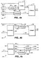
- Figs. 4a to 4c illustrate functional block diagrams of devices that create, change and respond to gain control words in an encoded information stream.
- Fig. 1a illustrates a stream of encoded audio information arranged in a sequence of audio blocks 10 through 18, and video information arranged in a sequence of video frames such as video frame 1.
- each video frame comprises two video fields that collectively define a single picture or image.
- Audio blocks 11 through 17 are grouped with video frame 1 into an encoded signal frame 21.
- Some applications have video frames that do not divide the encoded audio into an integer number of samples, transform coefficients, or the like. This can be accommodated by arranging groups of encoded signal frames into respective superframes. An arrangement of five encoded signal frames 21 through 25 grouped into superframe 31 is illustrated in Fig. 1b. This particular arrangement may be used for applications using NTSC video and 48 k sample/sec. PCM audio.
- a sequence of blocks of encoded audio information may represent overlapping intervals of an audio signaL
- Some split-band perceptual coding systems for example, process blocks of audio samples that overlap one another by half the block length.
- the samples in these overlapping blocks are modulated by an analysis window function.
- Fig. 2a illustrates the modulation envelopes 61 through 67 of an analysis window function applied to each block in a sequence of overlapping audio blocks.
- the length of the overlap is equal to one half the block length. This overlap interval is commonly used by some signal analysis-synthesis systems such as the O-TDAC transform mentioned above.
- Fig. 2b illustrates the resulting modulation envelope of a window function applied to a sequence of overlapping blocks for an encoded signal frame.
- the net effect or gain profile 81 of this modulation is the sum of the modulation envelopes 71 through 77 for adjacent blocks in the overlap intervals.
- the net effect across each overlap should be unity gain.
- Fig. 2c illustrates the overall effect of window function modulation across adjacent encoded signal fiames. As illustrated, gain profiles 80 through 82 overlap and add so that the net effect is unity gain.
- the net effect of all window function modulation is equivalent to the modulation effects of the analysis window function alone.
- the ideal gain profile can be achieved by ensuring that the modulation envelope of the analysis window function overlaps and adds to a constant.
- the net effect of all window function modulation is equivalent to that of a "product" window function formed from a product of the analysis window function and the synthesis window function.
- the ideal gain profile can be achieved by having the modulation envelope of the product window function add to a constant in the overlap interval.
- the shape of the analysis window function not only affects the gain profile of the signal but it also affects the frequency response characteristic of a corresponding filterbank.
- filterbanks having frequency response characteristics optimized for perceptual coding by increasing the attenuation of frequencies in the filter stopband in exchange for a broader filter passband.
- splice edits tend to generate significant spectral artifacts or "spectral splatter" within a range of frequencies that is not within the what is regarded as the filter stopband.
- Filterbanks that are designed to optimize general perceptual coding performance do not provide enough attenuation to render inaudible these spectral artifacts created at splice edits.
- the analysis window function together with a synthesis window function that is applied after application of the synthesis transform, must also satisfy a number of constraints to allow cancellation of the time-domain aliasing artifacts.
- the signal that is recovered from the synthesis transform can be conceptualized as a sum of the original signal and the time-domain aliasing components generaed by the analysis transform.
- curves 91, 93 and 95 represent segments of the amplitude envelope of an input signal as recovered from the inverse or synthesis transform and modulated by analysis and synthesis window functions.
- Curves 92, 94 and 96 represent the time-domain aliasing components as recovered from the inverse or synthesis transform and modulated by analysis and synthesis window functions.
- the time-domain aliasing components are reflected replicas of the original input signal as modulated by the analysis and synthesis window functions.
- the kernel functions of the analysis and synthesis O-TDAC transforms are designed to generate tie-domain aliasing components that are end-for-end reflections of the windowed signal in each half of a block.
- the O-TDAC transform generates time-domain aliasing components in two different regions. In region 2, the time-domain aliasing component is an end-for-end windowed reflection of the original signal in that region. In region 1, the time-domain aliasing component is an end-for-end windowed reflection of the input signal within that region, but the amplitude of the reflection is inverted.
- aliasing component 94a is an end-for-end windowed reflection of signal component 93a.
- Aliasing component 92b is also an end-for-end windowed reflection of signal component 91b except that the amplitude of the reflected component is inverted.
- the original signal is recovered and the aliasing components are cancelled.
- signal components 91b and 93a are added to recover the signal without window function modulation effects, and aliasing components 92b and 94a are added to cancel aliasing.
- signal components 93b and 95a are added to recover the signal and aliasing components 94b and 96a are added to cancel aliasing.
- Time-domain aliasing artifacts on either side of a splice boundary will generally not be cancelled because the aliasing artifacts in the half-block of synthesized audio samples immediately preceding the splice will not be the inverse of the aliasing artifacts in the half-block of synthesized audio block immediately after the splice.
- a technique that may be used to reduce the audibility of artifacts created by a splice is to incorporate into an encoded audio signal a plurality of gain-control words that instruct a decoder or playback system to alter the amplitude of the playback signal. Simple embodiments of devices that use these gain-control words are discussed in the following paragraphs.
- Fig. 4a illustrates a functional block diagram of device 100 in which format 111 generates along path 112 an output signal arranged in frames comprising video information, encoded audio information representing multiple audio channels, and gain-control words.
- Format 111 generates the output signal in response to a signal received from path 108 that is arranged in frames conveying video information and encoded audio information for the multiple audio channels, and in response to a signal received from path 110 that conveys gain-control words.
- Process 109 receives multiple control signals from paths 103a and 103b, each associated with one of the multiple audio channels, and in response to each control signal, generates along path 110 a pair of gain-control words for an associated audio channel that represent a starting gain and an ending gain within a respective frame. Only two control signals 103 and two associated audio channels 102 are shown in the figure for the sake of clarity. This gain-control technique may be applied to more that two channels if desired.
- encode 105 generates along paths 106a and 106b encoded audio information for multiple audio channels in response to multiple audio channel signals received from paths 102a and 102b, and frame 107 generates the signal along 108 by arranging in frames video information received from path 101 and the encoded audio information received from paths 106a and 106b.
- This gain-control technique may be used with input signals that are analogous to the signal passed along path 108; therefore, neither encode 105 nor frame 107 are required.
- encoding may be applied to each audio channel independently or it may be applied jointly to multiple audio channels.
- the AC-3 encoding technique may be applied jointly to two or more audio channels to lower total bandwidth requirements by removing or reducing redundancies between the channels.
- Fig. 4c illustrates a functional block diagram of device 140 that generates output signals to reproduce or playback multiple audio channels according to gain-control words in an input signal.
- Deformat 142 receives from path 141 an input signal arranged in frames comprising video information, encoded audio information and gain-control words.
- Deformat 142 obtains from each frame of the input signal encoded audio information representing multiple audio channels and obtains a pair of gain-control words associated with each of the audio channels.
- Process 148 receives the gain-control words from path 145 and in response generates gain control signals along paths 149a and 149b.
- Decode 146 receives the multiple channels of encoded audio information from paths 144a and 144b and in response generates an output signal for each audio channel such that the amplitude or level of each output signal is varied in response to an associated gain control signal.
- a pair of gain-control words represents a starting gain and an ending gain for a respective audio channel within a particular frame.
- Process 148 generates gain control signals representing an interpolation of the pair of gain-control words.
- the interpolation may follow any desired trajectory such as linear, quadratic, logarithmic or exponential. With linear interpolation, for example, a gain cool signal would represent a gain that changes linearly across a particular frame.
- Decoding may be applied to each audio channel independently or it may be applied jointly to multiple audio channels.
- decoding may be complementary to forms of encoding that remove or reduce redundancies between the channels.
- the output signal may be effectively modulated according to a gain control signal by modifying encoded audio prior to application of the synthesis filterbank, by modifying synthesized audio obtained from the synthesis filterbank prior to synthesis windowing, or by modifying the audio information obtained from the application of the synthesis window function.
- Fig. 4b illustrates a functional block diagram of device 120 that modifies existing gain-control words in a signal.
- Deformat 123 receives from path 121 an input signal arranged in frames comprising video information, encoded audio information representing multiple audio channels, and input gain-control words.
- Deformat 123 obtains from the input signal one or more input gain-control words associated with the encoded audio information for one of the multiple audio channels and passes the input gain control words along paths 124a and 124b.
- Process 126 generates one or more output gain-control words along path 127 by modifying one or more input gain-control words in response to a control signal received from path 122.
- Format 128 generates along path 129 an output signal that is arranged in frames including the video information, the encoded audio information for the multiple audio channels, the output gain control words and the input gain-control words that do not correspond to the output gain-control words.
- control signal 122 indicates a splice in input signal 121.
- process 126 generates one or more output gain-control words that will cause a device such as device 140 to attenuate a playback signal immediately prior to the splice and to reverse the attenuation immediately after the splice.
- the change in gain may extend across several frames; however, in many applications the change is limited to one frame on either side of the splice.
- the gain-change interval may be determined by balancing the audibility of modulation products produced by the gain change with the audibility of the gain change itself
- the gain-control word technique is not limited to editing applications.
Landscapes
- Engineering & Computer Science (AREA)
- Physics & Mathematics (AREA)
- Multimedia (AREA)
- Signal Processing (AREA)
- Spectroscopy & Molecular Physics (AREA)
- Acoustics & Sound (AREA)
- Health & Medical Sciences (AREA)
- Audiology, Speech & Language Pathology (AREA)
- Human Computer Interaction (AREA)
- Computer Networks & Wireless Communication (AREA)
- Computational Linguistics (AREA)
- Compression, Expansion, Code Conversion, And Decoders (AREA)
- Signal Processing For Digital Recording And Reproducing (AREA)
- Reduction Or Emphasis Of Bandwidth Of Signals (AREA)
- Transmission Systems Not Characterized By The Medium Used For Transmission (AREA)
- Tone Control, Compression And Expansion, Limiting Amplitude (AREA)
- Television Signal Processing For Recording (AREA)
- Two-Way Televisions, Distribution Of Moving Picture Or The Like (AREA)
- Stereophonic System (AREA)
- Control Of Amplification And Gain Control (AREA)
Applications Claiming Priority (3)
| Application Number | Priority Date | Filing Date | Title |
|---|---|---|---|
| US08/953,324 US5899969A (en) | 1997-10-17 | 1997-10-17 | Frame-based audio coding with gain-control words |
| US953324 | 1997-10-17 | ||
| PCT/US1998/021552 WO1999021371A1 (en) | 1997-10-17 | 1998-10-13 | Frame-based audio coding with gain-control words |
Publications (2)
| Publication Number | Publication Date |
|---|---|
| EP1023809A1 EP1023809A1 (en) | 2000-08-02 |
| EP1023809B1 true EP1023809B1 (en) | 2001-04-18 |
Family
ID=25493823
Family Applications (1)
| Application Number | Title | Priority Date | Filing Date |
|---|---|---|---|
| EP98952266A Expired - Lifetime EP1023809B1 (en) | 1997-10-17 | 1998-10-13 | Frame-based audio coding with gain-control words |
Country Status (11)
| Country | Link |
|---|---|
| US (1) | US5899969A (enExample) |
| EP (1) | EP1023809B1 (enExample) |
| JP (1) | JP4229586B2 (enExample) |
| KR (1) | KR100591009B1 (enExample) |
| AT (1) | ATE200722T1 (enExample) |
| AU (1) | AU755358B2 (enExample) |
| CA (1) | CA2305534C (enExample) |
| DE (1) | DE69800717T2 (enExample) |
| DK (1) | DK1023809T3 (enExample) |
| ES (1) | ES2156034T3 (enExample) |
| WO (1) | WO1999021371A1 (enExample) |
Families Citing this family (24)
| Publication number | Priority date | Publication date | Assignee | Title |
|---|---|---|---|---|
| JP4867076B2 (ja) * | 2001-03-28 | 2012-02-01 | 日本電気株式会社 | 音声合成用圧縮素片作成装置、音声規則合成装置及びそれらに用いる方法 |
| BR0205527A (pt) * | 2001-06-08 | 2003-07-08 | Koninkl Philips Electronics Nv | Métodos para editar um sinal de áudio original, e para decodificar um fluxo de áudio, editor de áudio, reprodutor de áudio, sistema de áudio, fluxo de áudio, e, meio de armazenagem |
| US20030187663A1 (en) | 2002-03-28 | 2003-10-02 | Truman Michael Mead | Broadband frequency translation for high frequency regeneration |
| US7941037B1 (en) * | 2002-08-27 | 2011-05-10 | Nvidia Corporation | Audio/video timescale compression system and method |
| KR101101384B1 (ko) * | 2003-04-24 | 2012-01-02 | 코닌클리케 필립스 일렉트로닉스 엔.브이. | 파라미터화된 시간 특징 분석 |
| WO2005093717A1 (en) * | 2004-03-12 | 2005-10-06 | Nokia Corporation | Synthesizing a mono audio signal based on an encoded miltichannel audio signal |
| US20060062407A1 (en) * | 2004-09-22 | 2006-03-23 | Kahan Joseph M | Sound card having feedback calibration loop |
| US8521314B2 (en) | 2006-11-01 | 2013-08-27 | Dolby Laboratories Licensing Corporation | Hierarchical control path with constraints for audio dynamics processing |
| JP5285626B2 (ja) * | 2007-03-01 | 2013-09-11 | ジェリー・マハバブ | 音声空間化及び環境シミュレーション |
| US8253609B2 (en) * | 2007-12-21 | 2012-08-28 | France Telecom | Transform-based coding/decoding, with adaptive windows |
| TWI591625B (zh) | 2009-05-27 | 2017-07-11 | 杜比國際公司 | 從訊號的低頻成份產生該訊號之高頻成份的系統與方法,及其機上盒、電腦程式產品、軟體程式及儲存媒體 |
| US11657788B2 (en) | 2009-05-27 | 2023-05-23 | Dolby International Ab | Efficient combined harmonic transposition |
| US9338523B2 (en) * | 2009-12-21 | 2016-05-10 | Echostar Technologies L.L.C. | Audio splitting with codec-enforced frame sizes |
| US9406303B2 (en) | 2011-11-18 | 2016-08-02 | Sirius Xm Radio Inc. | Systems and methods for implementing cross-fading, interstitials and other effects downstream |
| US9173025B2 (en) | 2012-02-08 | 2015-10-27 | Dolby Laboratories Licensing Corporation | Combined suppression of noise, echo, and out-of-location signals |
| US8712076B2 (en) | 2012-02-08 | 2014-04-29 | Dolby Laboratories Licensing Corporation | Post-processing including median filtering of noise suppression gains |
| CA2866585C (en) | 2012-03-06 | 2021-02-23 | Sirius Xm Radio Inc. | Systems and methods for audio attribute mapping |
| CA2870865C (en) | 2012-04-17 | 2020-08-18 | Sirius Xm Radio Inc. | Server side crossfading for progressive download media |
| CN104718572B (zh) * | 2012-06-04 | 2018-07-31 | 三星电子株式会社 | 音频编码方法和装置、音频解码方法和装置及采用该方法和装置的多媒体装置 |
| CN102739323B (zh) * | 2012-06-16 | 2013-09-04 | 天地融科技股份有限公司 | 音频数据传输方法 |
| TWI557727B (zh) * | 2013-04-05 | 2016-11-11 | 杜比國際公司 | 音訊處理系統、多媒體處理系統、處理音訊位元流的方法以及電腦程式產品 |
| EP2996269A1 (en) | 2014-09-09 | 2016-03-16 | Fraunhofer-Gesellschaft zur Förderung der angewandten Forschung e.V. | Audio splicing concept |
| US9536509B2 (en) | 2014-09-25 | 2017-01-03 | Sunhouse Technologies, Inc. | Systems and methods for capturing and interpreting audio |
| US11308928B2 (en) | 2014-09-25 | 2022-04-19 | Sunhouse Technologies, Inc. | Systems and methods for capturing and interpreting audio |
Family Cites Families (15)
| Publication number | Priority date | Publication date | Assignee | Title |
|---|---|---|---|---|
| US4551688A (en) * | 1984-05-23 | 1985-11-05 | Rockwell International Corporation | Delay compensated automatic gain control |
| US4625240A (en) * | 1984-07-25 | 1986-11-25 | Eeco, Inc. | Adaptive automatic gain control |
| US5109417A (en) * | 1989-01-27 | 1992-04-28 | Dolby Laboratories Licensing Corporation | Low bit rate transform coder, decoder, and encoder/decoder for high-quality audio |
| US5479562A (en) * | 1989-01-27 | 1995-12-26 | Dolby Laboratories Licensing Corporation | Method and apparatus for encoding and decoding audio information |
| NL9000338A (nl) * | 1989-06-02 | 1991-01-02 | Koninkl Philips Electronics Nv | Digitaal transmissiesysteem, zender en ontvanger te gebruiken in het transmissiesysteem en registratiedrager verkregen met de zender in de vorm van een optekeninrichting. |
| AU653582B2 (en) * | 1991-01-08 | 1994-10-06 | Dolby Laboratories Licensing Corporation | Encoder/decoder for multidimensional sound fields |
| US5394508A (en) * | 1992-01-17 | 1995-02-28 | Massachusetts Institute Of Technology | Method and apparatus for encoding decoding and compression of audio-type data |
| US5369724A (en) * | 1992-01-17 | 1994-11-29 | Massachusetts Institute Of Technology | Method and apparatus for encoding, decoding and compression of audio-type data using reference coefficients located within a band of coefficients |
| US5623577A (en) * | 1993-07-16 | 1997-04-22 | Dolby Laboratories Licensing Corporation | Computationally efficient adaptive bit allocation for encoding method and apparatus with allowance for decoder spectral distortions |
| US5451954A (en) * | 1993-08-04 | 1995-09-19 | Dolby Laboratories Licensing Corporation | Quantization noise suppression for encoder/decoder system |
| US5430485A (en) * | 1993-09-30 | 1995-07-04 | Thomson Consumer Electronics, Inc. | Audio/video synchronization in a digital transmission system |
| US5920842A (en) * | 1994-10-12 | 1999-07-06 | Pixel Instruments | Signal synchronization |
| HU215685B (hu) * | 1994-11-04 | 1999-02-01 | Koninklijke Philips Electronics N.V. | Eljárás és berendezés széles sávú digitális adatjelek kódolására és dekódolására |
| US5727119A (en) * | 1995-03-27 | 1998-03-10 | Dolby Laboratories Licensing Corporation | Method and apparatus for efficient implementation of single-sideband filter banks providing accurate measures of spectral magnitude and phase |
| ES2176722T3 (es) * | 1996-03-19 | 2002-12-01 | Dolby Lab Licensing Corp | Sistema de filtrado de analisis/sintesis con bancos de filtros eficaces de banda lateral unica con apilamiento no uniforme, que utiliza cancelacion de solapamiento de espectro en el dominio del tiempo. |
-
1997
- 1997-10-17 US US08/953,324 patent/US5899969A/en not_active Expired - Lifetime
-
1998
- 1998-10-13 ES ES98952266T patent/ES2156034T3/es not_active Expired - Lifetime
- 1998-10-13 CA CA002305534A patent/CA2305534C/en not_active Expired - Lifetime
- 1998-10-13 EP EP98952266A patent/EP1023809B1/en not_active Expired - Lifetime
- 1998-10-13 AT AT98952266T patent/ATE200722T1/de active
- 1998-10-13 DK DK98952266T patent/DK1023809T3/da active
- 1998-10-13 DE DE69800717T patent/DE69800717T2/de not_active Expired - Lifetime
- 1998-10-13 JP JP2000517559A patent/JP4229586B2/ja not_active Expired - Lifetime
- 1998-10-13 KR KR1020007003421A patent/KR100591009B1/ko not_active Expired - Lifetime
- 1998-10-13 AU AU98009/98A patent/AU755358B2/en not_active Expired
- 1998-10-13 WO PCT/US1998/021552 patent/WO1999021371A1/en not_active Ceased
Also Published As
| Publication number | Publication date |
|---|---|
| AU9800998A (en) | 1999-05-10 |
| KR100591009B1 (ko) | 2006-06-22 |
| JP2001521347A (ja) | 2001-11-06 |
| DE69800717T2 (de) | 2001-09-13 |
| DK1023809T3 (da) | 2001-05-07 |
| DE69800717D1 (de) | 2001-05-23 |
| ES2156034T3 (es) | 2001-06-01 |
| CA2305534A1 (en) | 1999-04-29 |
| KR20010024342A (ko) | 2001-03-26 |
| ATE200722T1 (de) | 2001-05-15 |
| AU755358B2 (en) | 2002-12-12 |
| WO1999021371A1 (en) | 1999-04-29 |
| JP4229586B2 (ja) | 2009-02-25 |
| CA2305534C (en) | 2007-03-27 |
| US5899969A (en) | 1999-05-04 |
| EP1023809A1 (en) | 2000-08-02 |
Similar Documents
| Publication | Publication Date | Title |
|---|---|---|
| EP1023809B1 (en) | Frame-based audio coding with gain-control words | |
| US6124895A (en) | Frame-based audio coding with video/audio data synchronization by dynamic audio frame alignment | |
| EP1023727B1 (en) | Frame-based audio coding with additional filterbank to suppress aliasing artifacts at frame boundaries | |
| EP1023730B1 (en) | Frame-based audio coding with additional filterbank to attenuate spectral splatter at frame boundaries | |
| US5913190A (en) | Frame-based audio coding with video/audio data synchronization by audio sample rate conversion | |
| JP2001521347A5 (enExample) |
Legal Events
| Date | Code | Title | Description |
|---|---|---|---|
| PUAI | Public reference made under article 153(3) epc to a published international application that has entered the european phase |
Free format text: ORIGINAL CODE: 0009012 |
|
| 17P | Request for examination filed |
Effective date: 20000414 |
|
| AK | Designated contracting states |
Kind code of ref document: A1 Designated state(s): AT BE CH DE DK ES FR GB IT LI NL SE |
|
| GRAG | Despatch of communication of intention to grant |
Free format text: ORIGINAL CODE: EPIDOS AGRA |
|
| 17Q | First examination report despatched |
Effective date: 20000907 |
|
| GRAG | Despatch of communication of intention to grant |
Free format text: ORIGINAL CODE: EPIDOS AGRA |
|
| GRAH | Despatch of communication of intention to grant a patent |
Free format text: ORIGINAL CODE: EPIDOS IGRA |
|
| GRAH | Despatch of communication of intention to grant a patent |
Free format text: ORIGINAL CODE: EPIDOS IGRA |
|
| ITF | It: translation for a ep patent filed | ||
| GRAA | (expected) grant |
Free format text: ORIGINAL CODE: 0009210 |
|
| AK | Designated contracting states |
Kind code of ref document: B1 Designated state(s): AT BE CH DE DK ES FR GB IT LI NL SE |
|
| REF | Corresponds to: |
Ref document number: 200722 Country of ref document: AT Date of ref document: 20010515 Kind code of ref document: T |
|
| ET | Fr: translation filed | ||
| REG | Reference to a national code |
Ref country code: CH Ref legal event code: NV Representative=s name: WILLIAM BLANC & CIE CONSEILS EN PROPRIETE INDUSTRI Ref country code: CH Ref legal event code: EP |
|
| REG | Reference to a national code |
Ref country code: DK Ref legal event code: T3 |
|
| REF | Corresponds to: |
Ref document number: 69800717 Country of ref document: DE Date of ref document: 20010523 |
|
| REG | Reference to a national code |
Ref country code: ES Ref legal event code: FG2A Ref document number: 2156034 Country of ref document: ES Kind code of ref document: T3 |
|
| REG | Reference to a national code |
Ref country code: GB Ref legal event code: IF02 |
|
| PLBE | No opposition filed within time limit |
Free format text: ORIGINAL CODE: 0009261 |
|
| STAA | Information on the status of an ep patent application or granted ep patent |
Free format text: STATUS: NO OPPOSITION FILED WITHIN TIME LIMIT |
|
| 26N | No opposition filed | ||
| REG | Reference to a national code |
Ref country code: CH Ref legal event code: PFA Owner name: DOLBY LABORATORIES LICENSING CORPORATION Free format text: DOLBY LABORATORIES LICENSING CORPORATION#100 POTRERO AVENUE#SAN FRANCISCO CALIFORNIA 94103-4813 (US) -TRANSFER TO- DOLBY LABORATORIES LICENSING CORPORATION#100 POTRERO AVENUE#SAN FRANCISCO CALIFORNIA 94103-4813 (US) |
|
| REG | Reference to a national code |
Ref country code: CH Ref legal event code: PCAR Free format text: NOVAGRAAF SWITZERLAND SA;CHEMIN DE L'ECHO 3;1213 ONEX (CH) |
|
| REG | Reference to a national code |
Ref country code: FR Ref legal event code: PLFP Year of fee payment: 18 |
|
| REG | Reference to a national code |
Ref country code: FR Ref legal event code: PLFP Year of fee payment: 19 |
|
| REG | Reference to a national code |
Ref country code: FR Ref legal event code: PLFP Year of fee payment: 20 |
|
| PGFP | Annual fee paid to national office [announced via postgrant information from national office to epo] |
Ref country code: DE Payment date: 20171027 Year of fee payment: 20 Ref country code: FR Payment date: 20171025 Year of fee payment: 20 Ref country code: DK Payment date: 20171025 Year of fee payment: 20 |
|
| PGFP | Annual fee paid to national office [announced via postgrant information from national office to epo] |
Ref country code: BE Payment date: 20171027 Year of fee payment: 20 Ref country code: AT Payment date: 20170920 Year of fee payment: 20 Ref country code: ES Payment date: 20171102 Year of fee payment: 20 Ref country code: GB Payment date: 20171027 Year of fee payment: 20 Ref country code: SE Payment date: 20171027 Year of fee payment: 20 Ref country code: IT Payment date: 20171024 Year of fee payment: 20 Ref country code: CH Payment date: 20171027 Year of fee payment: 20 Ref country code: NL Payment date: 20171026 Year of fee payment: 20 |
|
| REG | Reference to a national code |
Ref country code: DE Ref legal event code: R071 Ref document number: 69800717 Country of ref document: DE |
|
| REG | Reference to a national code |
Ref country code: CH Ref legal event code: PL Ref country code: DK Ref legal event code: EUP Effective date: 20181013 |
|
| REG | Reference to a national code |
Ref country code: NL Ref legal event code: MK Effective date: 20181012 |
|
| REG | Reference to a national code |
Ref country code: GB Ref legal event code: PE20 Expiry date: 20181012 |
|
| REG | Reference to a national code |
Ref country code: SE Ref legal event code: EUG |
|
| REG | Reference to a national code |
Ref country code: BE Ref legal event code: MK Effective date: 20181013 |
|
| REG | Reference to a national code |
Ref country code: AT Ref legal event code: MK07 Ref document number: 200722 Country of ref document: AT Kind code of ref document: T Effective date: 20181013 |
|
| PG25 | Lapsed in a contracting state [announced via postgrant information from national office to epo] |
Ref country code: GB Free format text: LAPSE BECAUSE OF EXPIRATION OF PROTECTION Effective date: 20181012 |
|
| REG | Reference to a national code |
Ref country code: ES Ref legal event code: FD2A Effective date: 20201204 |
|
| PG25 | Lapsed in a contracting state [announced via postgrant information from national office to epo] |
Ref country code: ES Free format text: LAPSE BECAUSE OF EXPIRATION OF PROTECTION Effective date: 20181014 |