EP1022536A1 - Générateur de gaz hybride muni d'un initiateur à chargement explosif profilé - Google Patents
Générateur de gaz hybride muni d'un initiateur à chargement explosif profilé Download PDFInfo
- Publication number
- EP1022536A1 EP1022536A1 EP00400054A EP00400054A EP1022536A1 EP 1022536 A1 EP1022536 A1 EP 1022536A1 EP 00400054 A EP00400054 A EP 00400054A EP 00400054 A EP00400054 A EP 00400054A EP 1022536 A1 EP1022536 A1 EP 1022536A1
- Authority
- EP
- European Patent Office
- Prior art keywords
- initiator
- pyrotechnic
- explosive
- gas generator
- enclosure
- Prior art date
- Legal status (The legal status is an assumption and is not a legal conclusion. Google has not performed a legal analysis and makes no representation as to the accuracy of the status listed.)
- Granted
Links
Images



Classifications
-
- B—PERFORMING OPERATIONS; TRANSPORTING
- B60—VEHICLES IN GENERAL
- B60R—VEHICLES, VEHICLE FITTINGS, OR VEHICLE PARTS, NOT OTHERWISE PROVIDED FOR
- B60R21/00—Arrangements or fittings on vehicles for protecting or preventing injuries to occupants or pedestrians in case of accidents or other traffic risks
- B60R21/02—Occupant safety arrangements or fittings, e.g. crash pads
- B60R21/16—Inflatable occupant restraints or confinements designed to inflate upon impact or impending impact, e.g. air bags
-
- B—PERFORMING OPERATIONS; TRANSPORTING
- B60—VEHICLES IN GENERAL
- B60R—VEHICLES, VEHICLE FITTINGS, OR VEHICLE PARTS, NOT OTHERWISE PROVIDED FOR
- B60R21/00—Arrangements or fittings on vehicles for protecting or preventing injuries to occupants or pedestrians in case of accidents or other traffic risks
- B60R21/02—Occupant safety arrangements or fittings, e.g. crash pads
- B60R21/16—Inflatable occupant restraints or confinements designed to inflate upon impact or impending impact, e.g. air bags
- B60R21/26—Inflatable occupant restraints or confinements designed to inflate upon impact or impending impact, e.g. air bags characterised by the inflation fluid source or means to control inflation fluid flow
- B60R21/268—Inflatable occupant restraints or confinements designed to inflate upon impact or impending impact, e.g. air bags characterised by the inflation fluid source or means to control inflation fluid flow using instantaneous release of stored pressurised gas
- B60R21/272—Inflatable occupant restraints or confinements designed to inflate upon impact or impending impact, e.g. air bags characterised by the inflation fluid source or means to control inflation fluid flow using instantaneous release of stored pressurised gas with means for increasing the pressure of the gas just before or during liberation, e.g. hybrid inflators
-
- F—MECHANICAL ENGINEERING; LIGHTING; HEATING; WEAPONS; BLASTING
- F42—AMMUNITION; BLASTING
- F42B—EXPLOSIVE CHARGES, e.g. FOR BLASTING, FIREWORKS, AMMUNITION
- F42B3/00—Blasting cartridges, i.e. case and explosive
- F42B3/04—Blasting cartridges, i.e. case and explosive for producing gas under pressure
- F42B3/045—Hybrid systems with previously pressurised gas using blasting to increase the pressure, e.g. causing the gas to be released from its sealed container
-
- F—MECHANICAL ENGINEERING; LIGHTING; HEATING; WEAPONS; BLASTING
- F42—AMMUNITION; BLASTING
- F42C—AMMUNITION FUZES; ARMING OR SAFETY MEANS THEREFOR
- F42C19/00—Details of fuzes
- F42C19/08—Primers; Detonators
- F42C19/09—Primers or detonators containing a hollow charge
Definitions
- the present invention relates to the field of automotive safety and relates more particularly to a hybrid gas generator including an initiator shaped explosive charge intended to inflate a protective cushion for vehicle occupant automobile.
- the skilled person is therefore always looking a low cost hybrid gas generator and low mass and size allowing the release of cold gases in the very first moments of generator operation, but also capable of contain an associated pyrotechnic charge housed at outside or inside the tank, and allowing inflate protective cushions as well frontal than side protective cushions.
- the object of the present invention is precisely to propose such a hybrid generator.
- the invention therefore relates to a gas generator hybrid comprising a reservoir having one end open in which is fixed an enclosure located at the outside of said tank and provided with orifices gas evacuation, said enclosure containing a ignition system and having a wall which can be open which initially allows to separate so waterproof the inside of the tank from inside the enclosure, said tank containing at least one gas under pressure, characterized in that the system ignition consists of a charging initiator profiled explosive capable of remotely causing destruction of the openable wall of said pregnant.
- the tank and the enclosure are generally cylindrical, the axis of revolution of said tank and the axis of revolution of said enclosure are and the profiled explosive charge initiator is located on this same axis.
- the enclosure can be made from a cylindrical hollow body having a side wall carrying the discharge openings of gas, a front wall carrying an opening initially closed with a cover and one end open in which is fixed a closure ring supporting the profiled explosive charge initiator.
- the initiator with explosive charge profile is an electrical initiator containing, part, a pyrotechnic priming composition relayed by a primary explosive relay, and on the other hand, a composite explosive comprising at least one binder and minus one nitramine, said composite explosive being shaped like a hollow charge.
- This primary explosive relay is for example constituted by penthrite or silver azide and initiate the explosive composite forming the profiled load.
- This guy initiator is very effective in delivering a dart whose field of action is very wide.
- an associated pyrotechnic charge may be housed in the compound.
- This pyrotechnic charge is lit by the explosive charge initiator profiled and allows, once part of the cold gas from the tank has started to inflate the protection, to generate gases coming to mix with the gas cold in order to fully deploy the cushion protection.
- the pyrotechnic charge associated is in the form of an annular block arranged around the profiled explosive charge initiator.
- the enclosure comprises a internal partition provided with an opening closed by a cover, said internal partition making it possible to divide said enclosure into a first initiation chamber and of combustion containing the loading initiator shaped explosive as well as pyrotechnic charge and in a second mixing and evacuation chamber gases with the wall that can be opened and the gas exhaust ports.
- this initiator which makes it possible to deliver a sting intended to fracture the wall which can be opened of the enclosure in order to release the cold gas contained in the tank, also has a weakened area lateral whose destruction in operation allows to the gases generated by the initiator to come into contact with the associated pyrotechnic charge. That is particularly advantageous when the latter is under the shape of an annular block arranged around initiator.
- the fragmentable cap contains a reinforcing powder interposed between the open end of the cap and the composition explosive which is in contact with the dug bottom, so that said reinforcing powder is arranged in look at the weakened area, which can consist of a thinned peripheral strip of the side wall of the cap or through port holes by said side wall and closed by lids. Also preferably, this reinforcing powder will be mixed with the primary relay explosive.
- the ignition support is consisting of an insulating support on which is deposited a resistive heating element as well as the composition initiating pyrotechnic, said resistive element heater which may consist for example of a semiconductor bridge or in a resistive wire which is connected to a current source using two conductive pins of the electric current constituting the system electrical initiation.
- an associated pyrotechnic charge may be housed in the tank and arranged opposite the wall which can be opened from the enclosure.
- This loading pyrotechnic is lit thanks to the dart delivered by the profiled explosive charge initiator and allows, once some of the cold gas from the tank has started inflating the airbag, generating gases coming to mix with cold gas in order to deploy totally the protective cushion.
- the pyrotechnic charge is placed inside a bucket with a bottom flat circular and a side wall whose end free is fixed in the enclosure.
- the flat circular bottom has a central hole closed by a cover and the pyrotechnic charge, on the one hand, is chocked by a separation ring fixed in the side wall of the bucket, and on the other hand, surrounds a relay device which rests on a central profiled nozzle of said separation ring.
- the side wall of the bucket has communication ports between its free end and the separation ring.
- the cap contains a powder reinforcer interposed between the open end of the cap and the explosive composition, so that that the reinforcing powder is placed opposite the weakened area.
- the explosive composition consists of a composite explosive comprising at least one binder and minus one nitramine.
- the cap contains a primary explosive relay.
- This explosive primary relay is advantageously mixed with a powder reinforcing and this mixture is interposed between the open end of the cap and the composition explosive, so as to be arranged facing the weakened area.
- the weakened area is constituted by a thinned peripheral strip of the side wall of the cap or through holes carried by said side wall and closed by covers.
- the diameter of the cap is at less than 8mm and the bottom is hollowed out in the shape of a cone, the latter having an opening angle at most equal at 30 °.
- the ignition support is consisting of an insulating support on which is deposited a resistive heating element as well as a composition initiating pyrotechnic, said resistive element heater which may consist for example of a semiconductor bridge or in a resistive wire placed in contact with the pyrotechnic initiation composition and which can be connected to a source of electrical current using a initiation system with two pins conductive.
- the initiation system can also be consisting of an optical cable associated with a device laser.
- a hybrid gas generator 1 is constituted from a tank 2 of generally cylindrical shape which has an open end fixed by welding in a enclosure 3 itself of generally cylindrical shape, the axis of revolution 4 of the tank 2 being merged with that of enclosure 3.
- the tank 2 contains a gas 10 inert cold under pressure, for example argon, which is initially introduced by a valve 11 closed by welding.
- the enclosure 3 is produced using a body cylindrical hollow 5 which has, on the one hand, a wall side provided with gas discharge ports 6, this side wall ending in an open end in which is fixed by screwing a ring closure 7, and on the other hand, a front wall 8 which carries an opening initially closed by a cover 9.
- An internal partition 14 which is fixed in the wall side of the hollow body 5 by snap-fastening in perforations 18 and which is provided with an opening 15 closed with a seal, divides enclosure 3 into one first initiation and combustion chamber 40 and in a second gas mixing and evacuation chamber 17 containing the front wall 8 as well as the orifices gas evacuation 6.
- a pyrotechnic module is maintained in the initiation and combustion chamber 40 using the closing ring 7 and this module pyrotechnic consists of a ring of wedging 16 into which an envelope 38 is inserted cylindrical.
- This timing ring 16 has, from a hand, a bottom with a central orifice resting against the internal partition 3, and on the other hand, one end now opened by crimping an initiator holder 32 in which a loading initiator 12 is inserted profiled pyrotechnics which will be described in more detail away and that is itself surrounded by a load pyrotechnic 13.
- the latter has the form of a block annular and the axis of revolution of this block as well as of the initiator 12 coincides with the axis of revolution 4.
- a spring 37 housed between the initiator holder 32 and the annular block allows, with the help of the casing 38 cylindrical, to maintain said block in a position stable.
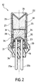
- the initiator 12 with explosive charge profile is made from an ignition support 19 comprising, on the one hand, a discoid insulating support 20 enclosed by a washer 21 in which is fixed by crimping the free end of the side wall 27 a fragmentary cylindrical cap 22, and the other part, a resistive heating element 23 in the form of thin semiconductor metal plates placed on the insulating support 20 and themselves covered by a ignition pyrotechnic composition 24.
- a system initiation to connect the initiator 12 to a electric current source (not shown) is made up of two pins 25a and 25b of metal partially enclosed in the insulating support 20 and each having one end in contact with the thin semiconductor plates.
- the cap 22 has a bottom 26 dug into a cone and its side wall 27 has a weakened area in the form of a band thinned peripheral device 28.
- the cap 22 contains a explosive composition 29 which is in contact with the mower 26 and which fills said cap 22 over about half a length of its side wall 27.
- This composition explosive 29, which is made from an explosive composite comprising at least one binder such as polybutadiene or poly (glycidyl azide) and at least a nitramine such as hexogen or octogen, is compactly maintained using a stud 30 cylindrical which rests on one of the two open ends of a cylindrical liner 31 of which the other open end abuts the washer 21.
- This stud 30 has a perforation central 33 and the liner 31 has a strip thin annular 34 arranged opposite the strip thinned peripheral 28 of the cap 22.
- the cap 22 also contains a mixture 35 containing a powder reinforcer and a primary relay explosive such as penthrite, this mixture 35 filling the defined volume by stud 30, liner 31 and thin plates semiconductors covered by the composition initiating pyrotechnics 24.
- thermoplastic resin partially coats the two pins 25a and 25b metallic and ensures, with the cap 22, sealing from the initiator 12.
- a firing current is delivered by the current source and is transmitted to the resistive heating element 23 of the initiator 12 by the metal pins 25a and 25b, which causes ignition by joule effect of the composition pyrotechnic ignition 24, this ignition then the initiation in detonation of the primary explosive relay of the mixture 35 and consequently the initiation into detonation of the explosive composition 29 by the central perforation 33 of the pad 30.
- the detonation wave thus created gives birth, when it reaches the apex of the bottom 26, to a piercing dart along the axis of revolution 4. This dart will successively break the envelope 38, then the cover closing the opening 15 and the seal 9 closing the opening carried by the wall frontal 8 of the hollow body 5.
- the inert cold gas 10 can then begin to escape through said opening, enter the mixing and evacuation chamber gas 17 to finally escape through the orifices gas evacuation 6 and initiate deployment of the protective cushion (not shown).
- the gases generated by the combustion of the reinforcing powder of the mixture 35 successively lead to the destruction of the band thin annular 34 of the sleeve 31 and of the strip thinned device 28 of the cap 22.
- These gases then enter the initiation chamber and combustion 40 and cause the ignition of the load pyrotechnic 13.
- the gases generated by the latter pass through the envelope 38 as well as the opening 15, then mix with the inert cold gas from the tank 2 in the mixing and evacuation chamber gases 17 and this mixture finally escapes through the gas exhaust ports 6 to inflate totally the protective cushion.
- this generator 101 is constituted from a tank 102 of generally cylindrical shape which has an open end fixed by welding in an enclosure 103 itself of general shape cylindrical.
- the tank 102 contains a cold gas 110 inert under pressure which is introduced by a valve 111.
- the enclosure 103 is produced using a body hollow 105 which has, on the one hand, a side wall provided with gas discharge orifices 106, this wall side ending with an open end in which is fixed by crimping a closure ring 107, and on the other hand, a front wall 108 which carries an opening initially closed by a cover 109.
- An initiator 112 with explosive charge profiled according to the invention is inserted in the closure ring 107 and is arranged opposite the cover 109.
- a firing order is transmitted to the initiator 112 and the latter then delivers a sting allowing the perforation of the cover 109.
- the gas 110 inert cold can therefore escape from the tank 102 then pass through the gas exhaust ports 106 to finally inflate the protective cushion.
- this generator 201 is formed from a tank 202 of generally cylindrical shape which has an open end fixed by welding in an enclosure 203 itself of general shape cylindrical.
- the enclosure 203 is produced using a hollow body 205 which has, on the one hand, a wall side fitted with gas discharge ports 206, this side wall ending in one end open in which a ring is fixed by crimping closure 207, and on the other hand, a front wall 208 which carries an opening initially closed by a lid 209.
- An initiator 212 with explosive charge profile according to the invention is inserted into the ring closure 207 and is arranged opposite the cover 209.
- the tank 202 contains a 250 cylindrical cup having, on the one hand, a flat circular bottom 251 which has a central hole closed by a cover 252, and on the other hand, a side wall 253 whose end free is fixed by welding in enclosure 203.
- a separation ring 254 is fixed by crimping in the side wall 253 of bucket 250 and has a nozzle 255 profile central unit on which a device rests ignition relay 256.
- a pyrotechnic charge 213 in the form of pellets is arranged around the device priming relay 256 and fills the volume delimited by the separation ring 254, the flat circular bottom 251 and the side wall 253 of the bucket 250, the latter having communication ports 257 no sealed between its free end and the ring separation 254.
- the tank 202 also contains a gas 210 inert cold under pressure introduced by a valve 211.
- a firing order is transmitted to the initiator 212 and the latter then delivers a dart for perforating the cover 209.
- the gas 210 inert cold under pressure can therefore start to escape from the tank 202 then cross the openings 206 gas evacuation system to initiate deployment of the protective cushion.
- the dart delivered by the initiator 212 also causes the initiation of the device priming relay 256 which will drive itself ignition of the pyrotechnic charge 213.
- the priming relay device can decompose, from a part, in a primer housed in the central opening, and on the other hand, into a fragmentable cap which contains a reinforcing pyrotechnic composition which overcomes said primer, the pyrotechnic charge then being arranged around the cap.
Landscapes
- Engineering & Computer Science (AREA)
- General Engineering & Computer Science (AREA)
- Mechanical Engineering (AREA)
- Physics & Mathematics (AREA)
- Fluid Mechanics (AREA)
- Air Bags (AREA)
- Feeding, Discharge, Calcimining, Fusing, And Gas-Generation Devices (AREA)
- Agricultural Chemicals And Associated Chemicals (AREA)
Abstract
Description
- il ne nécessite pas d'organe mécanique de libération des gaz,
- il permet au gaz froid contenu dans le réservoir d'amorcer le gonflage du coussin de protection grâce à une ouverture dudit réservoir à distance,
- il peut contenir un chargement pyrotechnique associé générateur de gaz aussi bien dans l'enceinte que dans le réservoir,
- il permet de gonfler un coussin de protection latéral de faible volume, la source de gaz nécessaire pour gonfler le coussin pouvant alors provenir exclusivement du gaz contenu sous pression dans le réservoir.
Claims (29)
- Générateur de gaz hybride (1,101,201) comprenant un réservoir (2,102,202) présentant une extrémité ouverte dans laquelle est fixée une enceinte (3,103,203) située à l'extérieur dudit réservoir (2,102,202) et munie d'orifices d'évacuation des gaz (6,106,206), ladite enceinte (3,103,203) renfermant un système d'allumage et comportant une paroi pouvant être ouverte qui permet initialement de séparer de façon étanche l'intérieur du réservoir (2,102,202) de l'intérieur de l'enceinte (3,103,203), ledit réservoir (2,102,202) contenant au moins un gaz sous pression, caractérisé en ce que le système d'allumage est constitué par un initiateur (12,112,212) à chargement explosif profilé apte à provoquer à distance la destruction de la paroi pouvant être ouverte de ladite enceinte (3,103,203).
- Générateur de gaz hybride (1,101,201) selon la revendication 1, caractérisé en ce que,i) ledit réservoir (2,102,202) et ladite enceinte (3,103,203) sont de forme générale cylindrique, l'axe de révolution (4) du réservoir (2,102,202) et l'axe de révolution de l'enceinte (3,103,203) étant confondus,ii) l'initiateur (12,112,212) à chargement explosif profilé est situé sur l'axe de révolution (4) dudit réservoir (2,102,202) et de ladite enceinte (3,103,203).
- Générateur de gaz hybride (1,101,201) selon la revendication 2, caractérisé en ce que l'enceinte (3,103,203) est réalisée à partir d'un corps creux (5,105,205) cylindrique présentant une paroi latérale portant les orifices d'évacuation des gaz (6,106,206), une paroi frontale (8,108,208) portant une ouverture initialement fermée par un opercule (9,109,209) et une extrémité ouverte dans laquelle est fixée une bague de fermeture (7,107,207) supportant l'initiateur (12,112,212) à chargement explosif profilé.
- Générateur de gaz hybride (1,101,201) selon la revendication 1, caractérisé en ce que l'initiateur (12,112,212) à chargement explosif profilé est un initiateur électrique contenant:i) une composition pyrotechnique d'amorçage (24) relayée par un explosif primaire relais,ii) un explosif composite comprenant au moins un liant et au moins une nitramine, ledit explosif composite étant profilé en forme de charge creuse.
- Générateur de gaz hybride (1) selon la revendication 4, caractérisé en ce qu'un chargement pyrotechnique (13) est logé dans l'enceinte (3).
- Générateur de gaz hybride (1) selon la revendication 5, caractérisé en ce que le chargement pyrotechnique (13) est sous la forme d'un bloc annulaire disposé autour de l'initiateur (12) à chargement explosif profilé.
- Générateur de gaz hybride (1) selon l'une quelconque des revendications 5 ou 6, caractérisé en ce que ladite enceinte (3) comporte une cloison interne (14) munie d'une ouverture (15) fermée par un opercule, ladite cloison interne (14) permettant de diviser ladite enceinte (3) en une première chambre d'initiation et de combustion (40) contenant l'initiateur (12) à chargement explosif profilé ainsi que le chargement pyrotechnique (13) et en une seconde chambre de mélange et d'évacuation des gaz (17) présentant la paroi pouvant être ouverte et les orifices d'évacuation des gaz (6).
- Générateur de gaz hybride (1) selon la revendication 6, caractérisé en ce que l'initiateur (12) à chargement explosif profilé est constitué à l'aidei) d'un support d'allumage (19),ii) d'un capuchon (22) fragmentable présentant un fond (26) creusé, une paroi latérale (27) et une extrémité ouverte fixée sur le support d'allumage (19), ledit capuchon (22) renfermant au moins une composition explosive (29) à base de nitramine et ladite paroi latérale comportant au moins une zone fragilisée,iii) et d'un système d'initiation électrique reliant le support d'allumage (19) à une source de courant.
- Générateur de gaz hybride (1) selon la revendication 8, caractérisé en ce que le capuchon (22) renferme une poudre renforçatrice intercalée entre l'extrémité ouverte du capuchon (22) et la composition explosive (29) qui est au contact du fond (26), de manière à ce que ladite poudre renforçatrice soit disposée en regard de la zone fragilisée.
- Générateur de gaz hybride (1) selon la revendication 8, caractérisé en ce que la zone fragilisée est constituée par une bande périphérique amincie (28) de la paroi latérale (27).
- Générateur de gaz hybride (1) selon la revendication 8, caractérisée en ce que le support d'allumage (19) est constitué par un support isolant (20) sur lequel est déposé un élément résistif chauffant (23) ainsi que la composition pyrotechnique d'amorçage (24).
- Générateur de gaz hybride (1) selon la revendication 11, caractérisé en ce que le système d'initiation électrique est constitué par deux broches (25a , 25b) conductrices du courant électrique qui sont reliées à l'élément résistif chauffant (23).
- Générateur de gaz hybride (1) selon la revendication 11, caractérisé en ce que l'élément résistif chauffant est un pont semi-conducteur.
- Générateur de gaz hybride (201) selon la revendication 4, caractérisé en ce que le réservoir (202) contient un chargement pyrotechnique (213) disposé en regard de la paroi pouvant être ouverte de l'enceinte (203).
- Générateur de gaz hybride (201) selon la revendication 14, caractérisé en ce que ledit chargement pyrotechnique (213) est placé à l'intérieur d'un godet (250) possédant un fond circulaire plat (251) et une paroi latérale (253) dont l'extrémité libre est fixée dans ladite enceinte (203).
- Générateur de gaz hybride (201) selon la revendication 15, caractérisé en ce que ledit fond circulaire plat (251) comporte un trou central fermé par un opercule (252) et en ce que ledit chargement pyrotechnique (213) est calé par une bague de séparation (254) fixée dans la paroi latérale (253) du godet (250) et entoure un dispositif relais d'amorçage (256) qui repose sur un ajutage central profilé (255) de ladite bague de séparation (254).
- Générateur de gaz hybride (201) selon la revendication 16, caractérisé en ce que la paroi latérale (253) du godet (250) comporte des orifices de communication (257) entre son extrémité libre et la bague de séparation (254).
- Initiateur électro-pyrotechnique (12) comprenant notamment un support d'allumage (19) dans lequel est fixée l'extrémité ouverte d'un capuchon (22) fragmentable renfermant au moins une composition explosive (29) et un système d'initiation qui permet de relier ledit support d'allumage (19) à une source de courant électrique, caractérisé en ce que,i) le capuchon (22) présente un fond (26) creusé dont la surface intérieure est au contact de la composition explosive (29),ii) le capuchon (22) présente une paroi latérale (27) comportant au moins une zone fragilisée.
- Initiateur électro-pyrotechnique (12) selon la revendication 18, caractérisé en ce que la composition explosive (29) est constituée par un explosif composite comportant au moins un liant et au moins une nitramine.
- Initiateur électro-pyrotechnique (12) selon la rvendication 19, caractérisé en ce que le capuchon (22) renferme un explosif primaire relais.
- Initiateur électro-pyrotechnique (12) selon la revendication 18, caractérisé en ce que le capuchon (22) renferme une poudre renforçatrice intercalée entre l'extrémité ouverte du capuchon (22) et la composition explosive (29), de manière à ce que la poudre renforçatrice soit disposée en regard de la zone fragilisée.
- Initiateur électro-pyrotechnique (12) selon la revendication 19, caractérisé en ce que le capuchon (22) renferme un mélange (35) composé d'une poudre renforçatrice et d'un explosif primaire relais, ledit mélange (35) étant intercalé entre l'extrémité ouverte du capuchon (22) et la composition explosive (29) de manière à être disposé en regard de la zone fragilisée.
- Initiateur électro-pyrotechnique (12) selon la revendication 18, caractérisé en ce que la zone fragilisée est constituée par une bande périphérique amincie (28) de la paroi latérale (27).
- Initiateur électro-pyrotechnique (12) selon la revendication 18, caractérisé en ce que le diamètre du capuchon (22) est au moins égal à 8mm.
- Initiateur électro-pyrotechnique (12) selon la revendication 18, caractérisé en ce que ledit fond (26) est creusé en forme de cône et présente un angle d'ouverture au plus égal à 30°.
- Initiateur électro-pyrotechnique (12) selon la revendication 18, caractérisé en ce que le support d'allumage (19) est constitué par un support isolant (20) sur lequel est déposé un élément résistif chauffant (23) ainsi qu'une composition pyrotechnique d'amorçage (24).
- Initiateur électro-pyrotechnique (12) selon la revendication 26, caractérisé en ce que le système d'initiation est constitué par deux broches (25a , 25b) conductrices du courant électrique qui sont reliées à l'élément résistif chauffant (23).
- Initiateur électro-pyrotechnique (12) selon la revendication 26, caractérisé en ce que ledit élément résistif chauffant (23) est un pont semi-conducteur.
- Initiateur électro-pyrotechnique (12) selon la revendication 26, caractérisé en ce que l'élément résistif chauffant est un fil résistif disposé au contact de la composition pyrotechnique d'amorçage (24).
Applications Claiming Priority (2)
| Application Number | Priority Date | Filing Date | Title |
|---|---|---|---|
| FR9900747 | 1999-01-25 | ||
| FR9900747A FR2788846B1 (fr) | 1999-01-25 | 1999-01-25 | Generateur de gaz hybride muni d'un initiateur a chargement explosif profile |
Publications (2)
| Publication Number | Publication Date |
|---|---|
| EP1022536A1 true EP1022536A1 (fr) | 2000-07-26 |
| EP1022536B1 EP1022536B1 (fr) | 2003-12-17 |
Family
ID=9541164
Family Applications (1)
| Application Number | Title | Priority Date | Filing Date |
|---|---|---|---|
| EP00400054A Expired - Lifetime EP1022536B1 (fr) | 1999-01-25 | 2000-01-11 | Générateur de gaz hybride muni d'un initiateur à chargement explosif profilé |
Country Status (9)
| Country | Link |
|---|---|
| US (1) | US6338500B1 (fr) |
| EP (1) | EP1022536B1 (fr) |
| JP (1) | JP3316200B2 (fr) |
| KR (1) | KR100381317B1 (fr) |
| AT (1) | ATE256854T1 (fr) |
| BR (1) | BR0000159B1 (fr) |
| DE (1) | DE60007184T2 (fr) |
| ES (1) | ES2211461T3 (fr) |
| FR (1) | FR2788846B1 (fr) |
Cited By (4)
| Publication number | Priority date | Publication date | Assignee | Title |
|---|---|---|---|---|
| FR2907732A1 (fr) * | 2006-10-27 | 2008-05-02 | Livbag Soc Par Actions Simplif | Generateur de gaz hybride de gonflage d'un coussin de securite pour vehicule automobile |
| FR2926631A1 (fr) | 2008-01-18 | 2009-07-24 | Livbag Soc Par Actions Simplif | Allumeur electro-pyrotechnique perforant et generateur en faisant usage |
| US20220003528A1 (en) * | 2020-07-06 | 2022-01-06 | Viettel Group | Pyrotechnic Initiator device |
| AT526224A1 (de) * | 2022-07-05 | 2024-01-15 | Astotec Automotive Gmbh | Pyrotechnischer Aktuator |
Families Citing this family (27)
| Publication number | Priority date | Publication date | Assignee | Title |
|---|---|---|---|---|
| US20030197088A1 (en) * | 2001-02-08 | 2003-10-23 | Mark Folsom | Projectile diverter |
| DE10031751A1 (de) * | 2000-06-29 | 2002-01-10 | Welz Industrieprodukte Gmbh | Kaltgasgenerator |
| DE10031750A1 (de) * | 2000-06-29 | 2002-01-10 | Welz Industrieprodukte Gmbh | Kaltgasgenerator für ein Airbag-System |
| DE20016041U1 (de) * | 2000-09-15 | 2002-02-21 | Breed Automotive Technology, Inc., Lakeland, Fla. | Vorrichtung zum Antrieb eines Kolbens zum Freisetzen eines Füllgases aus einem Gasgenerator, insbesondere Gasspeicher |
| US6578487B2 (en) * | 2000-12-08 | 2003-06-17 | Special Devices, Inc. | Pyrotechnic initiator with a narrowed sleeve retaining a pyrotechnic charge and methods of making same |
| US6848365B2 (en) * | 2000-12-08 | 2005-02-01 | Special Devices, Inc. | Initiator with an internal sleeve retaining a pyrotechnic charge and methods of making same |
| JP2002308040A (ja) * | 2001-02-07 | 2002-10-23 | Nippon Kayaku Co Ltd | ガス発生器 |
| US6709011B2 (en) * | 2001-02-21 | 2004-03-23 | Autoliv Asp, Inc. | Leak detection enhancing insert for an airbag inflator assembly |
| US6644206B2 (en) * | 2001-12-21 | 2003-11-11 | Trw Inc. | Electrically actuatable initiator with output charge |
| JP3864823B2 (ja) * | 2002-03-28 | 2007-01-10 | トヨタ自動車株式会社 | イニシエータ、インフレータおよび車両の乗員頭部保護エアバッグ装置 |
| US7044501B2 (en) * | 2002-06-17 | 2006-05-16 | Daicel Chemical Industries, Ltd. | Inflator |
| US6659009B1 (en) | 2002-08-01 | 2003-12-09 | The United States Of America As Represented By The Secretary Of The Navy | Drilled-in filter for gas generating initiator |
| JP2004209342A (ja) * | 2002-12-27 | 2004-07-29 | Takata Corp | イニシエータ及びガス発生器 |
| US6979021B2 (en) * | 2003-08-07 | 2005-12-27 | Autoliv Asp, Inc. | Integral initiator assembly for use in inflator devices |
| JP2005225346A (ja) * | 2004-02-12 | 2005-08-25 | Daicel Chem Ind Ltd | エアバッグ用インフレータ |
| JP2006007815A (ja) * | 2004-06-22 | 2006-01-12 | Takata Corp | インフレータ及びエアバッグ装置 |
| US7226078B2 (en) * | 2004-08-27 | 2007-06-05 | Autoliv Asp, Inc. | Inflator projectile |
| US7316187B2 (en) * | 2004-09-17 | 2008-01-08 | Autoliv Asp, Inc. | Radial discharge actuator device |
| FR2877082B1 (fr) * | 2004-10-21 | 2007-01-19 | Ncs Pyrotechnie & Tech | Initiateur comportant une zone de fragilisation |
| FR2894658B1 (fr) * | 2005-12-13 | 2010-11-12 | Livbag | Generateur de gaz de type hybride, renfermant ue charge de metal. |
| JP5242268B2 (ja) * | 2008-07-10 | 2013-07-24 | 株式会社ダイセル | インフレータの組立方法 |
| JP5181971B2 (ja) * | 2008-09-25 | 2013-04-10 | 豊田合成株式会社 | ガス発生装置 |
| US8205631B2 (en) * | 2008-11-19 | 2012-06-26 | Autoliv Asp, Inc. | Active material actuated vent valve |
| US8056477B2 (en) * | 2009-06-10 | 2011-11-15 | Autoliv Asp, Inc. | Protection system for use with airbag inflators and initiators |
| DE102014103629B3 (de) * | 2014-03-17 | 2015-02-12 | Joachim Haase | Vorrichtung mit einem Gasgenerator zur Erzeugung einer Druckgasströmung |
| GB2537414B (en) * | 2015-04-17 | 2019-11-13 | Graviner Ltd Kidde | Pyrotechnic valve |
| FR3127924B1 (fr) * | 2021-10-12 | 2024-06-28 | Livbag Sas | Generateur de gaz pour coussin gonflable de securite avec element protecteur |
Citations (8)
| Publication number | Priority date | Publication date | Assignee | Title |
|---|---|---|---|---|
| US3191533A (en) * | 1963-01-23 | 1965-06-29 | Jet Res Ct Inc | Gas discharge apparatus |
| US3670925A (en) * | 1969-10-28 | 1972-06-20 | Atlas Chem Ind | Explosively activated glass valve |
| US5131680A (en) | 1991-03-19 | 1992-07-21 | Trw Vehicle Safety Systems Inc. | Inflator assembly |
| US5263740A (en) | 1991-12-17 | 1993-11-23 | Trw Inc. | Hybrid air bag inflator |
| EP0673809A1 (fr) * | 1994-03-18 | 1995-09-27 | Oea, Inc. | Gonfleur hybride à dispositif de déclenchement du débit basé sur une pressurisation rapide |
| US5468015A (en) * | 1994-06-21 | 1995-11-21 | Trw Vehicle Safety Systems Inc. | Apparatus for inflating an inflatable vehicle occupant restraint |
| US5602361A (en) | 1994-03-18 | 1997-02-11 | Oea, Inc. | Hybrid inflator |
| US5601308A (en) * | 1995-05-23 | 1997-02-11 | Trw Inc. | Inflator, inflation fluid heater and assembly methods |
Family Cites Families (10)
| Publication number | Priority date | Publication date | Assignee | Title |
|---|---|---|---|---|
| SE442674B (sv) * | 1984-05-14 | 1986-01-20 | Bofors Ab | Anordning vid inbyggnad av eltenddon |
| US5005486A (en) * | 1989-02-03 | 1991-04-09 | Trw Vehicle Safety Systems Inc. | Igniter for airbag propellant grains |
| US5782486A (en) * | 1993-07-16 | 1998-07-21 | New Lenox Industries, Inc. | Rapid gas-fill apparatus and method |
| US5531473A (en) * | 1994-05-31 | 1996-07-02 | Morton International, Inc. | Fluid fuel-containing initiator device for an air bag inflator |
| US5538278A (en) * | 1994-06-14 | 1996-07-23 | Ad Astram Enterprises, Inc. | Ignition train apparatus for hybrid airbag inflators |
| US5603525A (en) * | 1995-06-22 | 1997-02-18 | Trw Inc. | Air bag inflator initiator housing with stored fluid pressure relief |
| US5668345A (en) * | 1995-10-19 | 1997-09-16 | Morton International, Inc. | Airbag inflators employing coated porous substrates |
| FR2747772B1 (fr) | 1996-04-22 | 1999-08-06 | Livbag Snc | Initiateur a prise bifilaire autobloquante pour generateurs pyrotechniques de gaz |
| US6010153A (en) | 1997-02-21 | 2000-01-04 | Breed Automotive Technology, Inc. | Hybrid inflator for airbags |
| US6196584B1 (en) * | 1998-12-01 | 2001-03-06 | Trw Inc. | Initiator for air bag inflator |
-
1999
- 1999-01-25 FR FR9900747A patent/FR2788846B1/fr not_active Expired - Fee Related
-
2000
- 2000-01-11 ES ES00400054T patent/ES2211461T3/es not_active Expired - Lifetime
- 2000-01-11 EP EP00400054A patent/EP1022536B1/fr not_active Expired - Lifetime
- 2000-01-11 AT AT00400054T patent/ATE256854T1/de not_active IP Right Cessation
- 2000-01-11 DE DE60007184T patent/DE60007184T2/de not_active Expired - Lifetime
- 2000-01-18 KR KR10-2000-0002155A patent/KR100381317B1/ko not_active Expired - Fee Related
- 2000-01-24 US US09/490,146 patent/US6338500B1/en not_active Expired - Fee Related
- 2000-01-25 BR BRPI0000159-7A patent/BR0000159B1/pt not_active IP Right Cessation
- 2000-01-25 JP JP2000018062A patent/JP3316200B2/ja not_active Expired - Fee Related
Patent Citations (8)
| Publication number | Priority date | Publication date | Assignee | Title |
|---|---|---|---|---|
| US3191533A (en) * | 1963-01-23 | 1965-06-29 | Jet Res Ct Inc | Gas discharge apparatus |
| US3670925A (en) * | 1969-10-28 | 1972-06-20 | Atlas Chem Ind | Explosively activated glass valve |
| US5131680A (en) | 1991-03-19 | 1992-07-21 | Trw Vehicle Safety Systems Inc. | Inflator assembly |
| US5263740A (en) | 1991-12-17 | 1993-11-23 | Trw Inc. | Hybrid air bag inflator |
| EP0673809A1 (fr) * | 1994-03-18 | 1995-09-27 | Oea, Inc. | Gonfleur hybride à dispositif de déclenchement du débit basé sur une pressurisation rapide |
| US5602361A (en) | 1994-03-18 | 1997-02-11 | Oea, Inc. | Hybrid inflator |
| US5468015A (en) * | 1994-06-21 | 1995-11-21 | Trw Vehicle Safety Systems Inc. | Apparatus for inflating an inflatable vehicle occupant restraint |
| US5601308A (en) * | 1995-05-23 | 1997-02-11 | Trw Inc. | Inflator, inflation fluid heater and assembly methods |
Cited By (6)
| Publication number | Priority date | Publication date | Assignee | Title |
|---|---|---|---|---|
| FR2907732A1 (fr) * | 2006-10-27 | 2008-05-02 | Livbag Soc Par Actions Simplif | Generateur de gaz hybride de gonflage d'un coussin de securite pour vehicule automobile |
| FR2926631A1 (fr) | 2008-01-18 | 2009-07-24 | Livbag Soc Par Actions Simplif | Allumeur electro-pyrotechnique perforant et generateur en faisant usage |
| US20220003528A1 (en) * | 2020-07-06 | 2022-01-06 | Viettel Group | Pyrotechnic Initiator device |
| US11680780B2 (en) * | 2020-07-06 | 2023-06-20 | Viettel Group | Pyrotechnic initiator device |
| AT526224A1 (de) * | 2022-07-05 | 2024-01-15 | Astotec Automotive Gmbh | Pyrotechnischer Aktuator |
| AT526224B1 (de) * | 2022-07-05 | 2024-02-15 | Astotec Automotive Gmbh | Pyrotechnischer Aktuator |
Also Published As
| Publication number | Publication date |
|---|---|
| DE60007184D1 (de) | 2004-01-29 |
| JP2000211466A (ja) | 2000-08-02 |
| FR2788846B1 (fr) | 2001-10-26 |
| FR2788846A1 (fr) | 2000-07-28 |
| US6338500B1 (en) | 2002-01-15 |
| KR100381317B1 (ko) | 2003-04-26 |
| BR0000159B1 (pt) | 2008-11-18 |
| KR20000076481A (ko) | 2000-12-26 |
| EP1022536B1 (fr) | 2003-12-17 |
| DE60007184T2 (de) | 2004-09-02 |
| BR0000159A (pt) | 2000-10-24 |
| ATE256854T1 (de) | 2004-01-15 |
| ES2211461T3 (es) | 2004-07-16 |
| JP3316200B2 (ja) | 2002-08-19 |
Similar Documents
| Publication | Publication Date | Title |
|---|---|---|
| EP1022536B1 (fr) | Générateur de gaz hybride muni d'un initiateur à chargement explosif profilé | |
| EP0879739B1 (fr) | Générateur pyrotechnique de gaz adaptatif à chambres tubulaires pour coussin de protection | |
| EP0728634B1 (fr) | Générateur pyrotechnique de gaz pour coussin gonflable d'un véhicule automobile | |
| EP1053915B1 (fr) | Générateur hybride à pilier perforateur | |
| EP0757026B1 (fr) | Générateur pyrotechnique de gaz chauds pour coussin latéral de protection | |
| EP1160138B1 (fr) | Générateur hybride à pilier perforateur et à corps bi-tubulaire | |
| EP0864470A1 (fr) | Générateur pyrotechnique de gaz à débit et volume adaptables pour coussin de protection | |
| FR2759958A1 (fr) | Dispositif de gonflage hybride pour airbags | |
| FR2740545A1 (fr) | Generateur pyrotechnique de gaz,a debit variable,pour coussins de protection | |
| EP0870651B1 (fr) | Générateur pyrotechnique à débit et volume de gaz adaptables pour coussin de protection | |
| EP0901946B1 (fr) | Générateur pyrotechnique adaptatif de gaz pour coussin de protection avec dispositif de neutralisation | |
| FR2799708A1 (fr) | Structure metallique gonflable a chargement pyrotechnique integre | |
| FR2953008A1 (fr) | Generateur de gaz a gaz reactifs | |
| CA2404836C (fr) | Generateur de gaz hybride pour coussin gonflable de protection laterale applique a la securite automobile | |
| EP0916067B1 (fr) | Generateur hybride a injection gazeuse interne | |
| FR2855769A1 (fr) | Generateur de gaz du type a allumage a plusieurs etages | |
| EP0404644B1 (fr) | Dispositif électropyrotechnique destiné à déclencher le fonctionnement d'un générateur de gaz | |
| FR2907732A1 (fr) | Generateur de gaz hybride de gonflage d'un coussin de securite pour vehicule automobile | |
| FR2846699A1 (fr) | Dispositif pyrotechnique de dispersion d'un fluide liquide destine a la denaturation de valeurs, utilisant une piece a profil contondant | |
| FR2846697A1 (fr) | Dispositif pyrotechnique de dispersion d'un fluide liquide | |
| EP1551784A1 (fr) | Composition et generateur pyrotechnique, dispositif comprenant un tel generateur utilise en securite automobile | |
| FR2937295A1 (fr) | Generateur pyrotechnique de gaz a pont thermique | |
| FR2933929A1 (fr) | Generateur de gaz utilise en securite automobile. |
Legal Events
| Date | Code | Title | Description |
|---|---|---|---|
| PUAI | Public reference made under article 153(3) epc to a published international application that has entered the european phase |
Free format text: ORIGINAL CODE: 0009012 |
|
| AK | Designated contracting states |
Kind code of ref document: A1 Designated state(s): AT BE CH CY DE DK ES FI FR GB GR IE IT LI LU MC NL PT SE |
|
| AX | Request for extension of the european patent |
Free format text: AL;LT;LV;MK;RO;SI |
|
| 17P | Request for examination filed |
Effective date: 20010126 |
|
| AKX | Designation fees paid |
Free format text: AT BE CH CY DE DK ES FI FR GB GR IE IT LI LU MC NL PT SE |
|
| 17Q | First examination report despatched |
Effective date: 20010828 |
|
| RAP1 | Party data changed (applicant data changed or rights of an application transferred) |
Owner name: LIVBAG S.N.C. |
|
| GRAP | Despatch of communication of intention to grant a patent |
Free format text: ORIGINAL CODE: EPIDOSNIGR1 |
|
| GRAS | Grant fee paid |
Free format text: ORIGINAL CODE: EPIDOSNIGR3 |
|
| GRAA | (expected) grant |
Free format text: ORIGINAL CODE: 0009210 |
|
| AK | Designated contracting states |
Kind code of ref document: B1 Designated state(s): AT BE CH CY DE DK ES FI FR GB GR IE IT LI LU MC NL PT SE |
|
| PG25 | Lapsed in a contracting state [announced via postgrant information from national office to epo] |
Ref country code: CY Free format text: LAPSE BECAUSE OF FAILURE TO SUBMIT A TRANSLATION OF THE DESCRIPTION OR TO PAY THE FEE WITHIN THE PRESCRIBED TIME-LIMIT Effective date: 20031217 Ref country code: IE Free format text: LAPSE BECAUSE OF FAILURE TO SUBMIT A TRANSLATION OF THE DESCRIPTION OR TO PAY THE FEE WITHIN THE PRESCRIBED TIME-LIMIT Effective date: 20031217 Ref country code: FI Free format text: LAPSE BECAUSE OF FAILURE TO SUBMIT A TRANSLATION OF THE DESCRIPTION OR TO PAY THE FEE WITHIN THE PRESCRIBED TIME-LIMIT Effective date: 20031217 Ref country code: AT Free format text: LAPSE BECAUSE OF FAILURE TO SUBMIT A TRANSLATION OF THE DESCRIPTION OR TO PAY THE FEE WITHIN THE PRESCRIBED TIME-LIMIT Effective date: 20031217 Ref country code: NL Free format text: LAPSE BECAUSE OF FAILURE TO SUBMIT A TRANSLATION OF THE DESCRIPTION OR TO PAY THE FEE WITHIN THE PRESCRIBED TIME-LIMIT Effective date: 20031217 |
|
| REG | Reference to a national code |
Ref country code: GB Ref legal event code: FG4D Free format text: NOT ENGLISH |
|
| REG | Reference to a national code |
Ref country code: CH Ref legal event code: EP |
|
| PG25 | Lapsed in a contracting state [announced via postgrant information from national office to epo] |
Ref country code: LU Free format text: LAPSE BECAUSE OF NON-PAYMENT OF DUE FEES Effective date: 20040111 |
|
| REG | Reference to a national code |
Ref country code: IE Ref legal event code: FG4D Free format text: FRENCH |
|
| REF | Corresponds to: |
Ref document number: 60007184 Country of ref document: DE Date of ref document: 20040129 Kind code of ref document: P |
|
| PG25 | Lapsed in a contracting state [announced via postgrant information from national office to epo] |
Ref country code: CH Free format text: LAPSE BECAUSE OF NON-PAYMENT OF DUE FEES Effective date: 20040131 Ref country code: LI Free format text: LAPSE BECAUSE OF NON-PAYMENT OF DUE FEES Effective date: 20040131 Ref country code: MC Free format text: LAPSE BECAUSE OF NON-PAYMENT OF DUE FEES Effective date: 20040131 Ref country code: BE Free format text: LAPSE BECAUSE OF NON-PAYMENT OF DUE FEES Effective date: 20040131 |
|
| REG | Reference to a national code |
Ref country code: SE Ref legal event code: TRGR |
|
| GBT | Gb: translation of ep patent filed (gb section 77(6)(a)/1977) |
Effective date: 20040218 |
|
| PG25 | Lapsed in a contracting state [announced via postgrant information from national office to epo] |
Ref country code: GR Free format text: LAPSE BECAUSE OF FAILURE TO SUBMIT A TRANSLATION OF THE DESCRIPTION OR TO PAY THE FEE WITHIN THE PRESCRIBED TIME-LIMIT Effective date: 20040317 Ref country code: DK Free format text: LAPSE BECAUSE OF FAILURE TO SUBMIT A TRANSLATION OF THE DESCRIPTION OR TO PAY THE FEE WITHIN THE PRESCRIBED TIME-LIMIT Effective date: 20040317 |
|
| NLV1 | Nl: lapsed or annulled due to failure to fulfill the requirements of art. 29p and 29m of the patents act | ||
| REG | Reference to a national code |
Ref country code: ES Ref legal event code: FG2A Ref document number: 2211461 Country of ref document: ES Kind code of ref document: T3 |
|
| REG | Reference to a national code |
Ref country code: IE Ref legal event code: FD4D |
|
| BERE | Be: lapsed |
Owner name: LIVBAG S.N.C. Effective date: 20040131 |
|
| REG | Reference to a national code |
Ref country code: CH Ref legal event code: PL |
|
| PLBE | No opposition filed within time limit |
Free format text: ORIGINAL CODE: 0009261 |
|
| STAA | Information on the status of an ep patent application or granted ep patent |
Free format text: STATUS: NO OPPOSITION FILED WITHIN TIME LIMIT |
|
| 26N | No opposition filed |
Effective date: 20040920 |
|
| REG | Reference to a national code |
Ref country code: FR Ref legal event code: TP |
|
| PG25 | Lapsed in a contracting state [announced via postgrant information from national office to epo] |
Ref country code: PT Free format text: LAPSE BECAUSE OF NON-PAYMENT OF DUE FEES Effective date: 20040517 |
|
| PGFP | Annual fee paid to national office [announced via postgrant information from national office to epo] |
Ref country code: SE Payment date: 20091127 Year of fee payment: 11 |
|
| PGFP | Annual fee paid to national office [announced via postgrant information from national office to epo] |
Ref country code: GB Payment date: 20091127 Year of fee payment: 11 Ref country code: ES Payment date: 20100119 Year of fee payment: 11 Ref country code: FR Payment date: 20091210 Year of fee payment: 11 |
|
| PGFP | Annual fee paid to national office [announced via postgrant information from national office to epo] |
Ref country code: DE Payment date: 20091201 Year of fee payment: 11 |
|
| PG25 | Lapsed in a contracting state [announced via postgrant information from national office to epo] |
Ref country code: IT Free format text: LAPSE BECAUSE OF NON-PAYMENT OF DUE FEES Effective date: 20090111 |
|
| PGFP | Annual fee paid to national office [announced via postgrant information from national office to epo] |
Ref country code: IT Payment date: 20100112 Year of fee payment: 11 |
|
| PGRI | Patent reinstated in contracting state [announced from national office to epo] |
Ref country code: IT Effective date: 20110616 |
|
| REG | Reference to a national code |
Ref country code: SE Ref legal event code: EUG |
|
| GBPC | Gb: european patent ceased through non-payment of renewal fee |
Effective date: 20110111 |
|
| REG | Reference to a national code |
Ref country code: FR Ref legal event code: ST Effective date: 20110930 |
|
| PG25 | Lapsed in a contracting state [announced via postgrant information from national office to epo] |
Ref country code: FR Free format text: LAPSE BECAUSE OF NON-PAYMENT OF DUE FEES Effective date: 20110131 |
|
| PG25 | Lapsed in a contracting state [announced via postgrant information from national office to epo] |
Ref country code: GB Free format text: LAPSE BECAUSE OF NON-PAYMENT OF DUE FEES Effective date: 20110111 |
|
| REG | Reference to a national code |
Ref country code: DE Ref legal event code: R119 Ref document number: 60007184 Country of ref document: DE Effective date: 20110802 |
|
| PGRI | Patent reinstated in contracting state [announced from national office to epo] |
Ref country code: IT Effective date: 20110616 |
|
| REG | Reference to a national code |
Ref country code: ES Ref legal event code: FD2A Effective date: 20120220 |
|
| PG25 | Lapsed in a contracting state [announced via postgrant information from national office to epo] |
Ref country code: ES Free format text: LAPSE BECAUSE OF NON-PAYMENT OF DUE FEES Effective date: 20110112 |
|
| PG25 | Lapsed in a contracting state [announced via postgrant information from national office to epo] |
Ref country code: SE Free format text: LAPSE BECAUSE OF NON-PAYMENT OF DUE FEES Effective date: 20110112 |
|
| PG25 | Lapsed in a contracting state [announced via postgrant information from national office to epo] |
Ref country code: DE Free format text: LAPSE BECAUSE OF NON-PAYMENT OF DUE FEES Effective date: 20110802 |