EP0864470A1 - Générateur pyrotechnique de gaz à débit et volume adaptables pour coussin de protection - Google Patents
Générateur pyrotechnique de gaz à débit et volume adaptables pour coussin de protection Download PDFInfo
- Publication number
- EP0864470A1 EP0864470A1 EP98400496A EP98400496A EP0864470A1 EP 0864470 A1 EP0864470 A1 EP 0864470A1 EP 98400496 A EP98400496 A EP 98400496A EP 98400496 A EP98400496 A EP 98400496A EP 0864470 A1 EP0864470 A1 EP 0864470A1
- Authority
- EP
- European Patent Office
- Prior art keywords
- tube
- generator according
- side wall
- pyrotechnic
- cylindrical
- Prior art date
- Legal status (The legal status is an assumption and is not a legal conclusion. Google has not performed a legal analysis and makes no representation as to the accuracy of the status listed.)
- Granted
Links
Images

Classifications
-
- B—PERFORMING OPERATIONS; TRANSPORTING
- B60—VEHICLES IN GENERAL
- B60R—VEHICLES, VEHICLE FITTINGS, OR VEHICLE PARTS, NOT OTHERWISE PROVIDED FOR
- B60R21/00—Arrangements or fittings on vehicles for protecting or preventing injuries to occupants or pedestrians in case of accidents or other traffic risks
- B60R21/02—Occupant safety arrangements or fittings, e.g. crash pads
- B60R21/16—Inflatable occupant restraints or confinements designed to inflate upon impact or impending impact, e.g. air bags
- B60R21/26—Inflatable occupant restraints or confinements designed to inflate upon impact or impending impact, e.g. air bags characterised by the inflation fluid source or means to control inflation fluid flow
- B60R21/264—Inflatable occupant restraints or confinements designed to inflate upon impact or impending impact, e.g. air bags characterised by the inflation fluid source or means to control inflation fluid flow using instantaneous generation of gas, e.g. pyrotechnic
- B60R21/2644—Inflatable occupant restraints or confinements designed to inflate upon impact or impending impact, e.g. air bags characterised by the inflation fluid source or means to control inflation fluid flow using instantaneous generation of gas, e.g. pyrotechnic using only solid reacting substances, e.g. pellets, powder
-
- B—PERFORMING OPERATIONS; TRANSPORTING
- B60—VEHICLES IN GENERAL
- B60R—VEHICLES, VEHICLE FITTINGS, OR VEHICLE PARTS, NOT OTHERWISE PROVIDED FOR
- B60R21/00—Arrangements or fittings on vehicles for protecting or preventing injuries to occupants or pedestrians in case of accidents or other traffic risks
- B60R21/02—Occupant safety arrangements or fittings, e.g. crash pads
- B60R21/16—Inflatable occupant restraints or confinements designed to inflate upon impact or impending impact, e.g. air bags
- B60R21/26—Inflatable occupant restraints or confinements designed to inflate upon impact or impending impact, e.g. air bags characterised by the inflation fluid source or means to control inflation fluid flow
- B60R21/263—Inflatable occupant restraints or confinements designed to inflate upon impact or impending impact, e.g. air bags characterised by the inflation fluid source or means to control inflation fluid flow using a variable source, e.g. plural stage or controlled output
- B60R2021/2633—Inflatable occupant restraints or confinements designed to inflate upon impact or impending impact, e.g. air bags characterised by the inflation fluid source or means to control inflation fluid flow using a variable source, e.g. plural stage or controlled output with a plurality of inflation levels
-
- B—PERFORMING OPERATIONS; TRANSPORTING
- B60—VEHICLES IN GENERAL
- B60R—VEHICLES, VEHICLE FITTINGS, OR VEHICLE PARTS, NOT OTHERWISE PROVIDED FOR
- B60R21/00—Arrangements or fittings on vehicles for protecting or preventing injuries to occupants or pedestrians in case of accidents or other traffic risks
- B60R21/02—Occupant safety arrangements or fittings, e.g. crash pads
- B60R21/16—Inflatable occupant restraints or confinements designed to inflate upon impact or impending impact, e.g. air bags
- B60R21/26—Inflatable occupant restraints or confinements designed to inflate upon impact or impending impact, e.g. air bags characterised by the inflation fluid source or means to control inflation fluid flow
- B60R21/264—Inflatable occupant restraints or confinements designed to inflate upon impact or impending impact, e.g. air bags characterised by the inflation fluid source or means to control inflation fluid flow using instantaneous generation of gas, e.g. pyrotechnic
- B60R21/2644—Inflatable occupant restraints or confinements designed to inflate upon impact or impending impact, e.g. air bags characterised by the inflation fluid source or means to control inflation fluid flow using instantaneous generation of gas, e.g. pyrotechnic using only solid reacting substances, e.g. pellets, powder
- B60R2021/2648—Inflatable occupant restraints or confinements designed to inflate upon impact or impending impact, e.g. air bags characterised by the inflation fluid source or means to control inflation fluid flow using instantaneous generation of gas, e.g. pyrotechnic using only solid reacting substances, e.g. pellets, powder comprising a plurality of combustion chambers or sub-chambers
Definitions
- the invention relates to the field of security automotive and relates more particularly to a pyrotechnic hot gas generator for inflating protective cushions.
- US Patent 5,219,178 describes a generator pyrotechnics of hot gases for "passenger" which includes two combustion chambers each comprising a pyrotechnic charge and an initiator and which are separated from each other by a diffusion chamber.
- a first combustion chamber is ignited using an initiator and the gases generated by combustion of the pyrotechnic charge arrive, after filtration, in the diffusion chamber.
- These gases thus cause, within a period of the order of twenty milliseconds, a slow inflation phase of the protection, which makes it possible to correctly position the passenger in his seat.
- the second combustion chamber is then initiated and an inflation phase ensues rapid cushion which ensures total deployment of the cushion.
- this generator which modulates the inflation rate of the cushion, cannot limit, depending on the circumstances, the volume of final gas released into the cushion.
- European patent application EP 0 428 298 discloses a pyrotechnic generator of hot gases whose body consists of two separate cylinders of length different fitting on a link system. This generator thus has two combustion chambers who frame a diffusion chamber and who are each separated from the latter by a plate metal supported by the bonding system. According to severity of the shock, it is then possible to initiate either one of the two combustion chambers of your choice, either two rooms simultaneously. Thus, this system allows limit the volume of gas generated, but on the other hand not allow to modify the inflation speed of the cushion protection. In addition, the manufacture of such generator is relatively complex, which restricts considerably its application in the field of automotive safety.
- the skilled person is therefore looking for a pyrotechnic gas generator, the manufacture of which is easy and low cost allowing, depending on the case, either to release only a certain volume of gas and therefore inflate the protective cushion only partially, or to release a maximum volume of gas in order to fully inflate the cushion with the possibility of regulating the inflation speed.
- the pyrotechnic charge is consisting either of a chosen pyrotechnic composition in the group of so-called "double base" compositions, that is to say the nitrocellulose-based compositions and nitroglycerin, either by a composition composite pyrotechnics based on an organic binder and at least one oxidizing charge.
- each pyrotechnic charge is insulated from the side wall by an envelope cylindrical. So the disadvantage of so-called “double base" compositions which consist of that they deteriorate over time on contact of ferrous material is avoided, which ensures correct and reliable combustion of the load pyrotechnic.
- loading pyrotechnic consists of a composition pyrotechnic composite
- the cylindrical envelope which contains said pyrotechnic charge allows maintain sufficient pressure to ensure ignition of the load and protect the load against ambient humidity.
- the intermediate part provided of holes constitutes a diffuser.
- a filtration grid and support is placed between the pyrotechnic charge and the nozzle closed.
- a spring is placed between the closing ring and the pyrotechnic charge of so as to wedge said load against the grid of filtration.
- the envelope cylindrical in said upstream part and downstream part, encloses the spring, loading pyrotechnic and the filtration grid.
- the envelope cylindrical then comes in the form of a housing cylindrical - having a closed end plated against the nozzle and acting as a clickable seal.
- a cylindrical condenser is pressed, in the intermediate part, against the wall internal lateral of the tube.
- the condenser can for example be constituted by a winding of grids.
- each pyrotechnic charge is in the form of a cylindrical block perforated by a plurality of channels parallel to the axis of said block of so that said channels are parallel to the axis of revolution of the tube.
- the safety valve is housed in the part intermediate, facing the partition set into the wall lateral to the limit between the intermediate wall and the downstream part of the tube.
- the valve of security consists of a cylindrical piece monobloc comprising a peripheral crown connected by a tab to a central disc whose surface is at less equal to the outlet section of the mounted nozzle by said partition.
- Figure 1 is a longitudinal sectional view of a generator according to the invention.
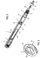
- FIG. 2 is a partially exploded perspective view of the generator shown in FIG. 1.
- FIG. 3 is a perspective view of the generator safety valve shown in FIGS. 1 and 2.
- a pyrotechnic hot gas generator comprises a cylindrical tube 1 made of a metal sufficiently ductile to be able to be crimped, that is to say a metal preferably having an elongation capacity greater than 20% and a breaking strength greater than 400 MPa.
- This tube 1 has two open ends and has a side wall 2 whose length L of the generators is greater than its outside diameter D. In the example shown in Figures 1 and 2, the length L is substantially equal to six times the outside diameter D.
- Two internal partitions 3, 4 each carrying a nozzle 5, 6 are crimped in the side wall 2 so as to divide the tube 1 into an upstream portion 7 continues, an intermediate portion 8 provided with holes 9 and a downstream portion 10 continues.
- the open end of the tube 1 is closed by a closing ring 11, 12 into which is inserted a electric igniter 13, 14 whose plug is protected by a shunt 15, 16.
- the igniter 13, 14 is surmounted by a 17.38 fragmentable metal cap containing an ignition powder, such as powder of the boron / potassium nitrate type, and is surrounded by a helical spring 18, 19.
- This spring 18, 19 is pressing both against the closing ring 11,12 and against one end of a cylindrical block 20,21 which constitutes the pyrotechnic charge and which is perforated by nineteen channels parallel to the axis of the block 20,21, this being coincident with the axis of revolution of the tube 1.
- a 24.25 cylindrical housing having a open end resting against the closing ring 11, 12 and a closed end pressed against the partition 3.4 internal serves as a clickable cover for the nozzle 5.6 carried by the latter and encloses the spring 18.19, the block 20, 21 and the filtration grid 22, 23.
- the length of the upstream part 7 is greater than that of the downstream part 10, and the block 20 located in said upstream part 7 is more important than that housed in said downstream part 10.
- a safety valve 26, consisting of a part cylindrical monobloc made of metal and comprising a peripheral crown 27 connected by a tongue 39 to a central disc 28 whose surface is at least equal at the outlet section of the nozzle 6, is placed in the intermediate part 8 facing the partition 4 which is set in the side wall 2 at the limit between the intermediate part 8 and the downstream part 10 of the tube 1.
- the central disc 28 then closes the outlet port of the nozzle 6.
- Such a generator coupled to a detection system multi-function, authorizes the diagrams of following operation.
- a signal emitted by a collision detector triggers the fire from the igniter 13 of the upstream part 7 which ignites then the ignition powder.
- the combustion gases which are generated cause the cap 17 to burst and come into contact with block 20, resulting in the ignition of said block 20.
- the breaking value of the housing 24 which closes the nozzle 5 the latter ruptures in the vicinity of said nozzle 5 and the gases penetrate into the intermediate part 8 of the tube 1, pass through the porous condenser 29 and escape through the holes 9 to inflate the cushion protection.
- the igniter 14 of the downstream part 10 is ignited following the igniter 13 according to a programmed delay in the time.
- block 21 is on and, when the pressure reaches a certain threshold, the housing 25 ruptures in the vicinity of the nozzle 6. The gases generated then exert pressure on the central disc 28 of the safety valve 26, which causes a folding of the tongue 39 in the direction of the gas flow. Gas thus penetrate into the intermediate part 8 to finally inflate the protective cushion.
Landscapes
- Physics & Mathematics (AREA)
- Fluid Mechanics (AREA)
- Engineering & Computer Science (AREA)
- Mechanical Engineering (AREA)
- Air Bags (AREA)
Abstract
Description
- soit de ne libérer qu'un volume de gaz limité, et donc de ne gonfler le coussin que partiellement, en initiant uniquement le système d'allumage logé dans la partie amont,
- soit de gonfler totalement le coussin de protection en initiant les deux systèmes d'allumage simultanément ou avec un certain décalage dans le temps, la mise à feu décalée permettant de moduler la vitesse de gonflage du coussin.
- D'une part, la fabrication ne met en oeuvre qu'un faible nombre de pièces dont l'assemblage peut être facilement automatisé, ce qui permet de réduire très sensiblement les coûts de fabrication, tout en garantissant un gonflage correct et fiable du coussin de protection.
- D'autre part, le fait de pouvoir jouer sur le volume de gaz généré ou sur la vitesse de gonflage du coussin assure une protection adaptée à la sévérité du choc.
Claims (10)
- Générateur pyrotechnique de gaz chauds destiné à la sécurité automobile comprenant notamment un tube (1) cylindrique présentant une paroi latérale (2) dont la longueur (L) des génératrices est supérieure à son diamètre extérieur (D), deux chargements pyrotechniques et deux systèmes d'allumage (13,14), caractérisé en ce que,i) le tube est monobloc,ii) deux cloisons (3,4) internes portant chacune une tuyère (5,6) initialement obturée sont serties dans ladite paroi latérale (2) de manière à diviser ledit tube (1) en une partie amont (7) continue, une partie intermédiaire (8) munie de trous (9) et une partie aval (10) continue, lesdites partie amont (7) et partie aval (10) contenant chacune un chargement pyrotechnique,iii) ledit tube (1) est fermé à chacune de ses extrémités par une bague de fermeture (11,12) dans laquelle est inséré un système d'allumage (13,14),iv) une valve de sécurité (26) est en appui contre la cloison (4) sertie dans la paroi latérale (2) à la limite entre la partie intermédiaire (8) et la partie aval (10) du tube (1) de manière à isoler la partie aval (10) des gaz provenant de la partie amont (7).
- Générateur selon la revendication 1, caractérisé en ce que chaque chargement pyrotechnique est isolé de la paroi latérale (2) par une enveloppe (24,25) cylindrique.
- Générateur selon la revendication 2, caractérisé en ce que la partie intermédiaire (8) munie de trous (9) constitue un diffuseur.
- Générateur selon la revendication 3, caractérisé en ce que, dans lesdites partie amont (7) et partie aval (10), une grille de filtration et d'appui (22,23) est placée entre le chargement pyrotechnique et la tuyère (5,6) obturée.
- Générateur selon la revendication 4, caractérisé en ce que, dans lesdites partie amont (7) et partie aval (10), un ressort (18,19) est placé entre la bague de fermeture (11,12) et le chargement pyrotechnique de manière à caler ledit chargement contre la grille de filtration (22,23).
- Générateur selon la revendication 5, caractérisé en ce que, dans lesdites partie amont (7) et partie aval (10), l'enveloppe (24,25) cylindrique enserre le ressort (18,19), le chargement pyrotechnique et la grille de filtration (22,23).
- Générateur selon l'une quelconque des revendications 5 ou 6, caractérisé en ce qu'un condenseur (29) cylindrique est plaqué, dans la partie intermédiaire (8), contre la paroi latérale (2) interne du tube (1).
- Générateur selon la revendication 1, caractérisé en ce que chaque chargement pyrotechnique est sous la forme d'un bloc (20,21) cylindrique perforé par une pluralité de canaux parallèles à l'axe dudit bloc (20,21) de manière à ce que lesdits canaux soient parallèles à l'axe de révolution du tube (1).
- Générateur selon la revendication 1, caractérisé en ce que la valve de sécurité (26) est logée dans la partie intermédiaire (8), face à la cloison (4) sertie dans la paroi latérale (2) à la limite entre la partie intermédiaire (8) et la partie aval (10) du tube (1).
- Générateur selon la revendication 9, caractérisé en ce que la valve de sécurité (26) est constituée par une pièce cylindrique monobloc comprenant une couronne périphérique (27) reliée par une languette (39) à un disque central (28) dont la surface est au moins égale à la section de sortie de la tuyère (6) portée par la cloison (4).
Applications Claiming Priority (2)
| Application Number | Priority Date | Filing Date | Title |
|---|---|---|---|
| FR9703062 | 1997-03-14 | ||
| FR9703062A FR2760710B1 (fr) | 1997-03-14 | 1997-03-14 | Generateur pyrotechnique de gaz a debit et volume adaptables pour coussin de protection |
Publications (2)
| Publication Number | Publication Date |
|---|---|
| EP0864470A1 true EP0864470A1 (fr) | 1998-09-16 |
| EP0864470B1 EP0864470B1 (fr) | 2001-10-17 |
Family
ID=9504761
Family Applications (1)
| Application Number | Title | Priority Date | Filing Date |
|---|---|---|---|
| EP98400496A Expired - Lifetime EP0864470B1 (fr) | 1997-03-14 | 1998-03-03 | Générateur pyrotechnique de gaz à débit et volume adaptables pour coussin de protection |
Country Status (5)
| Country | Link |
|---|---|
| US (1) | US5970880A (fr) |
| EP (1) | EP0864470B1 (fr) |
| JP (1) | JP3022961B2 (fr) |
| DE (1) | DE69802025T2 (fr) |
| FR (1) | FR2760710B1 (fr) |
Cited By (6)
| Publication number | Priority date | Publication date | Assignee | Title |
|---|---|---|---|---|
| EP1152929A1 (fr) * | 1999-02-26 | 2001-11-14 | Automotive Systems Laboratory Inc. | Generateur de gaz a deux chambres |
| US7237801B2 (en) | 2004-08-31 | 2007-07-03 | Automotive Systems Laboratory, Inc. | Gas generating system |
| US7267365B2 (en) | 2004-03-10 | 2007-09-11 | Automotive Systems Laboratory, Inc. | Inflator |
| US7806954B2 (en) | 2005-11-01 | 2010-10-05 | Automotive Systems Laboratory Inc. | Gas generator |
| US7814838B2 (en) | 2004-06-28 | 2010-10-19 | Automotive Systems, Laboratory, Inc. | Gas generating system |
| US8376400B2 (en) | 2006-04-21 | 2013-02-19 | Tk Holdings, Inc. | Gas generating system |
Families Citing this family (42)
| Publication number | Priority date | Publication date | Assignee | Title |
|---|---|---|---|---|
| DE19638838A1 (de) * | 1996-09-21 | 1998-03-26 | Dynamit Nobel Ag | Hybridgasgenerator für einen Airbag mit einem mechanischen Öffnungsmechanismus für die Speicherkammer |
| US6036226A (en) * | 1997-02-03 | 2000-03-14 | General Dynamics Armament Systems, Inc. | Inflator capable of modulation air bag inflation rate in a vehicle occupant restraint apparatus |
| DE29809062U1 (de) * | 1998-05-19 | 1998-10-08 | Trw Airbag Sys Gmbh & Co Kg | Mehrstufengasgenerator mit thermischer Entkoppelung der Treibsätze |
| US6701849B2 (en) | 1999-03-05 | 2004-03-09 | Trw Inc. | Dual stage air bag inflator with secondary propellant cap |
| US6196582B1 (en) * | 1999-09-22 | 2001-03-06 | Delphi Technologies, Inc. | Variable output inflator for an air bag |
| US7188567B1 (en) | 1999-11-12 | 2007-03-13 | Zodiac Automotive Us Inc. | Gas generation system |
| TW527294B (en) * | 1999-11-29 | 2003-04-11 | Daicel Chem | Gas generator for air bag and devices for the same |
| JP2001163171A (ja) * | 1999-12-10 | 2001-06-19 | Nippon Kayaku Co Ltd | ガス発生器 |
| FR2802873B1 (fr) * | 1999-12-23 | 2002-03-22 | Giat Ind Sa | Dispositif de securite pyrotechnique pour vehicule |
| JP5050298B2 (ja) * | 2000-05-19 | 2012-10-17 | タカタ株式会社 | ガス発生装置 |
| JP2002012125A (ja) * | 2000-06-29 | 2002-01-15 | Takata Corp | エアバッグインフレータ及びその製造方法 |
| US20030137135A1 (en) * | 2000-06-29 | 2003-07-24 | Welz Industrieprodukte Gmbh | Cold Gas Generator |
| US20030057689A1 (en) * | 2001-06-29 | 2003-03-27 | Nobuyuki Katsuda | Hybrid inflator |
| US6607214B2 (en) | 2001-08-17 | 2003-08-19 | Autoliv Asp, Inc. | Gas generation via indirect ignition |
| US6752421B2 (en) | 2002-01-03 | 2004-06-22 | Automotive Systems Laboratory, Inc. | Airbag inflator |
| US6886469B2 (en) * | 2002-05-17 | 2005-05-03 | Zodiac Automotive Us Inc. | Distributed charge inflator system |
| US7162958B2 (en) | 2002-05-17 | 2007-01-16 | Zodiac Automotive Us Inc. | Distributed charge inflator system |
| US7137341B2 (en) * | 2002-05-17 | 2006-11-21 | Zodiac Automotive Us Inc. | Distributed charge inflator system |
| US7703097B2 (en) * | 2002-11-15 | 2010-04-20 | International Business Machines Corporation | Auto-commit processing in an IMS batch application |
| US7438313B2 (en) * | 2003-08-06 | 2008-10-21 | Arc Automotive, Inc. | Compact multi-level output gas generator |
| US20050029785A1 (en) * | 2003-08-06 | 2005-02-10 | Arc Automotive, Inc. | Compact multi-level output hybrid gas generator |
| DE20313664U1 (de) * | 2003-09-03 | 2004-01-29 | Trw Airbag Systems Gmbh | Gasgenerator |
| US20050098988A1 (en) * | 2003-11-12 | 2005-05-12 | Smith Bradley W. | Pressure-enhanced, adaptive inflator device |
| JP2005239020A (ja) | 2004-02-27 | 2005-09-08 | Daicel Chem Ind Ltd | エアバッグ用ガス発生器 |
| US7413216B2 (en) * | 2004-02-27 | 2008-08-19 | Daicel Chemical Industries, Ltd. | Gas generator for an air bag |
| US7367584B2 (en) | 2004-04-19 | 2008-05-06 | Automotive Systems Laboratory, Inc. | Gas generating system |
| US7343862B2 (en) | 2004-05-27 | 2008-03-18 | Automotive Systems Laboratory, Inc. | Gas generating system |
| US7438315B2 (en) * | 2004-05-28 | 2008-10-21 | Automotive Systems Laboratory, Inc. | Inflator and method of assembly |
| FR2877428B1 (fr) * | 2004-10-29 | 2007-03-30 | Livbag Soc Par Actions Simplif | Generateur pyrotechnique a deux chambres de combustion et a charge d'allumage unique |
| FR2878210B1 (fr) * | 2004-11-25 | 2008-05-16 | Livbag Soc Par Actions Simplif | Dispositif de securite pour vehicule automobile a micro-generateur de gaz |
| US20060170201A1 (en) * | 2005-01-14 | 2006-08-03 | Daicel Chemical Industries, Ltd. | Multi-stage gas generator |
| US7537240B2 (en) * | 2005-02-22 | 2009-05-26 | Automotive Systems Laboratory, Inc. | Gas generating system |
| WO2007005824A2 (fr) * | 2005-06-30 | 2007-01-11 | Automotive Systems Laboratory, Inc. | Generateur de gaz |
| FR2888315B1 (fr) | 2005-07-05 | 2007-09-21 | Livbag Soc Par Actions Simplif | Generateur pyrotechnique de gaz destine a la securite automobile |
| US9427343B2 (en) * | 2007-06-22 | 2016-08-30 | David L. Bogert | Locked segments pushable stent-graft |
| US10154917B2 (en) * | 2007-06-22 | 2018-12-18 | C. R. Bard, Inc. | Helical and segmented stent-graft |
| DE102007037325B4 (de) * | 2007-08-08 | 2013-11-14 | Trw Airbag Systems Gmbh | Gasgenerator |
| FR2922006A1 (fr) | 2007-10-03 | 2009-04-10 | Livbag Soc Par Actions Simplif | Generateur de gaz dont la chambre de diffusion est pourvue d'un conduit interne |
| US7878535B2 (en) * | 2008-04-29 | 2011-02-01 | Arc Automotive, Inc. | Airbag inflator with adaptive valve |
| US8827308B1 (en) * | 2013-03-15 | 2014-09-09 | Autoliv Asp, Inc. | Filter with integrated baffle |
| DE102017116868A1 (de) * | 2017-07-26 | 2019-01-31 | Trw Airbag Systems Gmbh | Gasgenerator, Gassackmodul und Fahrzeugsicherheitssystem |
| DE102018112011A1 (de) * | 2018-05-18 | 2019-11-21 | Trw Airbag Systems Gmbh | Treibstoffkäfig für einen rohrgasgenerator, füllkörperelement für einen rohrgasgenerator, rohrgasgenerator für ein gassackmodul, gassackmodul, fahrzeugsicherheitssystem, verfahren zum betreiben und herstellen eines rohrgasgenerators |
Citations (4)
| Publication number | Priority date | Publication date | Assignee | Title |
|---|---|---|---|---|
| EP0428298A2 (fr) | 1989-11-13 | 1991-05-22 | Morton International, Inc. | Générateur de gaz présentant trois niveaux de performance |
| US5219178A (en) | 1990-10-08 | 1993-06-15 | Nippon Koki Co., Ltd. | Air bag inflation gas generator |
| EP0733519A2 (fr) * | 1995-03-22 | 1996-09-25 | Morton International, Inc. | Système de gonflage d'un coussin d'air à plusieurs étages |
| EP0757026A1 (fr) * | 1995-08-04 | 1997-02-05 | S.N.C. Livbag | Générateur pyrotechnique de gaz chauds pour coussin latéral de protection |
Family Cites Families (6)
| Publication number | Priority date | Publication date | Assignee | Title |
|---|---|---|---|---|
| US3972545A (en) * | 1975-03-10 | 1976-08-03 | Thiokol Corporation | Multi-level cool gas generator |
| US4950458A (en) * | 1989-06-22 | 1990-08-21 | Morton International, Inc. | Passenger automotive restraint generator |
| US5799973A (en) * | 1995-04-22 | 1998-09-01 | Temic Bayern-Chemie Airbag Gmbh | Pyrotechnic gas generator with two separate combustion chambers |
| US5645298A (en) * | 1996-01-05 | 1997-07-08 | Trw Inc./Trw Vehicle Safety Systems, Inc. | Inflator for an inflatable vehicle occupant protection device |
| US5671946A (en) * | 1996-02-28 | 1997-09-30 | Trw Vehicle Safety Systems Inc. | Apparatus for inflating a vehicle occupant protection device |
| US5794973A (en) * | 1996-12-04 | 1998-08-18 | Trw Vehicle Safety Systems Inc. | Dual stage air bag inflator |
-
1997
- 1997-03-14 FR FR9703062A patent/FR2760710B1/fr not_active Expired - Fee Related
-
1998
- 1998-03-03 EP EP98400496A patent/EP0864470B1/fr not_active Expired - Lifetime
- 1998-03-03 DE DE69802025T patent/DE69802025T2/de not_active Expired - Lifetime
- 1998-03-13 JP JP10063045A patent/JP3022961B2/ja not_active Expired - Fee Related
- 1998-03-16 US US09/039,423 patent/US5970880A/en not_active Expired - Fee Related
Patent Citations (4)
| Publication number | Priority date | Publication date | Assignee | Title |
|---|---|---|---|---|
| EP0428298A2 (fr) | 1989-11-13 | 1991-05-22 | Morton International, Inc. | Générateur de gaz présentant trois niveaux de performance |
| US5219178A (en) | 1990-10-08 | 1993-06-15 | Nippon Koki Co., Ltd. | Air bag inflation gas generator |
| EP0733519A2 (fr) * | 1995-03-22 | 1996-09-25 | Morton International, Inc. | Système de gonflage d'un coussin d'air à plusieurs étages |
| EP0757026A1 (fr) * | 1995-08-04 | 1997-02-05 | S.N.C. Livbag | Générateur pyrotechnique de gaz chauds pour coussin latéral de protection |
Cited By (7)
| Publication number | Priority date | Publication date | Assignee | Title |
|---|---|---|---|---|
| EP1152929A1 (fr) * | 1999-02-26 | 2001-11-14 | Automotive Systems Laboratory Inc. | Generateur de gaz a deux chambres |
| EP1152929A4 (fr) * | 1999-02-26 | 2004-11-17 | Automotive Systems Lab | Generateur de gaz a deux chambres |
| US7267365B2 (en) | 2004-03-10 | 2007-09-11 | Automotive Systems Laboratory, Inc. | Inflator |
| US7814838B2 (en) | 2004-06-28 | 2010-10-19 | Automotive Systems, Laboratory, Inc. | Gas generating system |
| US7237801B2 (en) | 2004-08-31 | 2007-07-03 | Automotive Systems Laboratory, Inc. | Gas generating system |
| US7806954B2 (en) | 2005-11-01 | 2010-10-05 | Automotive Systems Laboratory Inc. | Gas generator |
| US8376400B2 (en) | 2006-04-21 | 2013-02-19 | Tk Holdings, Inc. | Gas generating system |
Also Published As
| Publication number | Publication date |
|---|---|
| JP3022961B2 (ja) | 2000-03-21 |
| DE69802025T2 (de) | 2002-06-06 |
| DE69802025D1 (de) | 2001-11-22 |
| FR2760710A1 (fr) | 1998-09-18 |
| FR2760710B1 (fr) | 1999-04-23 |
| EP0864470B1 (fr) | 2001-10-17 |
| JPH10315899A (ja) | 1998-12-02 |
| US5970880A (en) | 1999-10-26 |
Similar Documents
| Publication | Publication Date | Title |
|---|---|---|
| EP0864470B1 (fr) | Générateur pyrotechnique de gaz à débit et volume adaptables pour coussin de protection | |
| EP0879739B1 (fr) | Générateur pyrotechnique de gaz adaptatif à chambres tubulaires pour coussin de protection | |
| EP0728634B1 (fr) | Générateur pyrotechnique de gaz pour coussin gonflable d'un véhicule automobile | |
| EP1053915B1 (fr) | Générateur hybride à pilier perforateur | |
| EP0757026B1 (fr) | Générateur pyrotechnique de gaz chauds pour coussin latéral de protection | |
| EP1160138B1 (fr) | Générateur hybride à pilier perforateur et à corps bi-tubulaire | |
| EP0856140B1 (fr) | Generateur pyrotechnique de gaz, a debit adaptable, pour coussins de protection | |
| EP0849131A1 (fr) | Générateur tubulaire intégral de gaz par voie pyrotechnique, pour gonfler des coussins de protection | |
| EP0870651B1 (fr) | Générateur pyrotechnique à débit et volume de gaz adaptables pour coussin de protection | |
| FR2902060A1 (fr) | "generateur pyrotechnique de gaz utilise en securite automobile" | |
| FR2691706A1 (fr) | Générateur pyrotechnique de gaz muni d'une ouverture de sécurité. | |
| EP0901946B1 (fr) | Générateur pyrotechnique adaptatif de gaz pour coussin de protection avec dispositif de neutralisation | |
| FR2625960A1 (fr) | Dispositif de retenue secondaire de securite pour passagers d'un vehicule a moteur | |
| EP1304267B1 (fr) | Générateur de gaz hybride pour un airbag | |
| CA2404836C (fr) | Generateur de gaz hybride pour coussin gonflable de protection laterale applique a la securite automobile | |
| FR2855769A1 (fr) | Generateur de gaz du type a allumage a plusieurs etages | |
| EP0849130B1 (fr) | Générateur pyrotechnique de gaz à chargement composite | |
| EP0916067B1 (fr) | Generateur hybride a injection gazeuse interne | |
| FR2831123A1 (fr) | Dispositif generateur de gaz hybride utilise en securite automobile pour gonfler un coussin de protection lateral | |
| FR2877297A1 (fr) | Generateur pyrotechnique de gaz destine a la securite automobile | |
| FR2885682A1 (fr) | Generateur pyrotechnique de gaz | |
| FR2937295A1 (fr) | Generateur pyrotechnique de gaz a pont thermique | |
| FR2943600A1 (fr) | Generateur de gaz pour un dispositif de securite pour vehicule automobile |
Legal Events
| Date | Code | Title | Description |
|---|---|---|---|
| PUAI | Public reference made under article 153(3) epc to a published international application that has entered the european phase |
Free format text: ORIGINAL CODE: 0009012 |
|
| AK | Designated contracting states |
Kind code of ref document: A1 Designated state(s): DE FR SE |
|
| AX | Request for extension of the european patent |
Free format text: AL;LT;LV;MK;RO;SI |
|
| 17P | Request for examination filed |
Effective date: 19990316 |
|
| AKX | Designation fees paid |
Free format text: DE FR SE |
|
| RBV | Designated contracting states (corrected) |
Designated state(s): DE FR SE |
|
| GRAG | Despatch of communication of intention to grant |
Free format text: ORIGINAL CODE: EPIDOS AGRA |
|
| GRAG | Despatch of communication of intention to grant |
Free format text: ORIGINAL CODE: EPIDOS AGRA |
|
| GRAH | Despatch of communication of intention to grant a patent |
Free format text: ORIGINAL CODE: EPIDOS IGRA |
|
| 17Q | First examination report despatched |
Effective date: 20010321 |
|
| GRAH | Despatch of communication of intention to grant a patent |
Free format text: ORIGINAL CODE: EPIDOS IGRA |
|
| GRAA | (expected) grant |
Free format text: ORIGINAL CODE: 0009210 |
|
| AK | Designated contracting states |
Kind code of ref document: B1 Designated state(s): DE FR SE |
|
| REF | Corresponds to: |
Ref document number: 69802025 Country of ref document: DE Date of ref document: 20011122 |
|
| PLBE | No opposition filed within time limit |
Free format text: ORIGINAL CODE: 0009261 |
|
| STAA | Information on the status of an ep patent application or granted ep patent |
Free format text: STATUS: NO OPPOSITION FILED WITHIN TIME LIMIT |
|
| 26N | No opposition filed | ||
| REG | Reference to a national code |
Ref country code: FR Ref legal event code: TP |
|
| PGFP | Annual fee paid to national office [announced via postgrant information from national office to epo] |
Ref country code: SE Payment date: 20090123 Year of fee payment: 12 |
|
| EUG | Se: european patent has lapsed | ||
| PGFP | Annual fee paid to national office [announced via postgrant information from national office to epo] |
Ref country code: FR Payment date: 20110210 Year of fee payment: 14 |
|
| PGFP | Annual fee paid to national office [announced via postgrant information from national office to epo] |
Ref country code: DE Payment date: 20120111 Year of fee payment: 15 |
|
| PG25 | Lapsed in a contracting state [announced via postgrant information from national office to epo] |
Ref country code: SE Free format text: LAPSE BECAUSE OF NON-PAYMENT OF DUE FEES Effective date: 20100304 |
|
| REG | Reference to a national code |
Ref country code: FR Ref legal event code: ST Effective date: 20121130 |
|
| PG25 | Lapsed in a contracting state [announced via postgrant information from national office to epo] |
Ref country code: FR Free format text: LAPSE BECAUSE OF NON-PAYMENT OF DUE FEES Effective date: 20120402 |
|
| REG | Reference to a national code |
Ref country code: DE Ref legal event code: R119 Ref document number: 69802025 Country of ref document: DE Effective date: 20131001 |
|
| PG25 | Lapsed in a contracting state [announced via postgrant information from national office to epo] |
Ref country code: DE Free format text: LAPSE BECAUSE OF NON-PAYMENT OF DUE FEES Effective date: 20131001 |