EP1022488A1 - Tendeur pour courroie, circuit cinématique et moteur comportant un tel tendeur - Google Patents
Tendeur pour courroie, circuit cinématique et moteur comportant un tel tendeur Download PDFInfo
- Publication number
- EP1022488A1 EP1022488A1 EP00400073A EP00400073A EP1022488A1 EP 1022488 A1 EP1022488 A1 EP 1022488A1 EP 00400073 A EP00400073 A EP 00400073A EP 00400073 A EP00400073 A EP 00400073A EP 1022488 A1 EP1022488 A1 EP 1022488A1
- Authority
- EP
- European Patent Office
- Prior art keywords
- tensioner
- cage
- support means
- tensioner according
- belt
- Prior art date
- Legal status (The legal status is an assumption and is not a legal conclusion. Google has not performed a legal analysis and makes no representation as to the accuracy of the status listed.)
- Granted
Links
Images


Classifications
-
- F—MECHANICAL ENGINEERING; LIGHTING; HEATING; WEAPONS; BLASTING
- F16—ENGINEERING ELEMENTS AND UNITS; GENERAL MEASURES FOR PRODUCING AND MAINTAINING EFFECTIVE FUNCTIONING OF MACHINES OR INSTALLATIONS; THERMAL INSULATION IN GENERAL
- F16H—GEARING
- F16H7/00—Gearings for conveying rotary motion by endless flexible members
- F16H7/08—Means for varying tension of belts, ropes or chains
- F16H7/10—Means for varying tension of belts, ropes or chains by adjusting the axis of a pulley
- F16H7/12—Means for varying tension of belts, ropes or chains by adjusting the axis of a pulley of an idle pulley
- F16H7/1209—Means for varying tension of belts, ropes or chains by adjusting the axis of a pulley of an idle pulley with vibration damping means
- F16H7/1218—Means for varying tension of belts, ropes or chains by adjusting the axis of a pulley of an idle pulley with vibration damping means of the dry friction type
-
- F—MECHANICAL ENGINEERING; LIGHTING; HEATING; WEAPONS; BLASTING
- F16—ENGINEERING ELEMENTS AND UNITS; GENERAL MEASURES FOR PRODUCING AND MAINTAINING EFFECTIVE FUNCTIONING OF MACHINES OR INSTALLATIONS; THERMAL INSULATION IN GENERAL
- F16H—GEARING
- F16H7/00—Gearings for conveying rotary motion by endless flexible members
- F16H7/08—Means for varying tension of belts, ropes or chains
- F16H2007/0802—Actuators for final output members
- F16H2007/0806—Compression coil springs
-
- F—MECHANICAL ENGINEERING; LIGHTING; HEATING; WEAPONS; BLASTING
- F16—ENGINEERING ELEMENTS AND UNITS; GENERAL MEASURES FOR PRODUCING AND MAINTAINING EFFECTIVE FUNCTIONING OF MACHINES OR INSTALLATIONS; THERMAL INSULATION IN GENERAL
- F16H—GEARING
- F16H7/00—Gearings for conveying rotary motion by endless flexible members
- F16H7/08—Means for varying tension of belts, ropes or chains
- F16H2007/0876—Control or adjustment of actuators
- F16H2007/0878—Disabling during transport
-
- F—MECHANICAL ENGINEERING; LIGHTING; HEATING; WEAPONS; BLASTING
- F16—ENGINEERING ELEMENTS AND UNITS; GENERAL MEASURES FOR PRODUCING AND MAINTAINING EFFECTIVE FUNCTIONING OF MACHINES OR INSTALLATIONS; THERMAL INSULATION IN GENERAL
- F16H—GEARING
- F16H7/00—Gearings for conveying rotary motion by endless flexible members
- F16H7/08—Means for varying tension of belts, ropes or chains
- F16H2007/0889—Path of movement of the finally actuated member
- F16H2007/0893—Circular path
Definitions
- the present invention relates mainly to a belt tensioner, with a kinematic circuit and with a motor comprising a such a tensioner.
- a belt tensioner in a kinematic chain comprising a movement transmission belt between a driving pulley and one or more driven pulleys.
- a tensioner usually includes a piston-cylinder guide device in translation of a first assembly secured with a first end of the tensioner, attached directly or indirectly to the engine block, relative to a second assembly secured with a second end of the tensioner bearing a roller running on the belt, the two assemblies being surrounded by a helical spring for returning to the separated position of said assemblies.
- Hydraulic damping means equip the achievements improved tensioners of known types. Such tensioners, although generally satisfactory, are of a high cost price. Moreover, some achievements have a large size and / or a duration limited life.
- the use of a return spring radially external requires fixing the tensioner of the type known by one of the ends said tensioner. Such attachment is not necessarily the most rigid or the one that best adapts to the reduced space available in the compartment engine.
- a tensioner comprising a rigid cage advantageously provided with means of mounting, for example on an engine block or on a turntable mounted on such an engine block.
- a rigid piece carrying, preferably at one of its ends, means of support on a belt, including a pebble.
- Elastic means for returning to a position away from the cage and the part supporting the roller preferably a spring, typically a coil spring, are mounted inside said room.
- the axis of the spring coincides with the axis longitudinal of the rigid cage, itself confused with that of the part carrying the roller.
- the present invention also relates to a tensioner, characterized in that the anchoring element has openings or fixing bolt eyelets.
- the present invention also relates to a tensioner, characterized in that it comprises a layer interposed between the rigid cage and the opposite face of the support means so as to provide guidance, and friction providing cushioning to the tensioner.
- the present invention also relates to a tensioner, characterized in that the intermediate layer is made of elastomer.
- the present invention also relates to a tensioner, characterized in that the rigid cage and the support means have a section substantially rectangular.
- the present invention also relates to a tensioner, characterized in that the support means on the belt comprise a roller.
- the present invention also relates to a tensioner, characterized in that the locking means comprise a first projecting element integral with the cage, a second projecting element integral with the support means and a removable coupling part for these two elements salient.
- the present invention also relates to a tensioner, characterized in that the projecting elements include pieces of sheet metal folded of the cage and support means and in that the coupling piece is a pin passing through openings made in said elements salient.
- the present invention also relates to a tensioner, characterized in that it includes means for limiting the travel of support means support means on the belt to prevent them from get out of the cage.
- FIGS. 1 to 16 the same references have been used for designate the same elements.
- a tensioner 1 comprising a cage 3 advantageously prismatic, for example in the form of rectangular parallelepiped with rounded edges having an opening 5 on the front face.
- the cage 3 is for example made of 2 mm sheet steel thick and has a height of 70 mm and a base of 50 mm x 35 mm.
- the upper end of the cage is closed by two edges 7.1 and 7.2 folded at 90 ° and superimposed over part of their length.
- the tensioner according to the present invention is capable of being secured to its support, in particular with the engine block of an engine internal combustion thermal, by any known fixing means.
- the openings 9 are provided in lugs 13 produced by deploying the metal sheet from the cutouts 55 made in the side walls 57 of the cage 3.
- the rear wall 53 of the cage 3 has a height greater than that of the other faces and has openings for receiving fixing bolts.
- the inner wall of the cage 3 is lined with a layer 15 of a material making it possible to control, in particular to reduce, the friction during the sliding of an internal part 17 bearing by means of a yoke 19, a roller 21 bearing on a belt 23.
- the friction between the part 17 and the cage 3 are determined, in particular by the contact surface and by the coefficient of friction.
- a low and constant coefficient of friction is obtained by the use of PTFE.
- An increase in friction results an increase in amortization but a decrease in the response in frequency of the tensioner according to the present invention.
- a high coefficient of friction is obtained, for example, by the use of a layer 15 made of elastomer, especially of the natural rubber type for temperatures moderate operating, butadiene nitril rubber, advantageously loaded with lubricant such as graphite or HNBR (hydrogenated nitril butadiene ribber or NBR in English terminology) covered with lubricant film such as grease.
- the elastomer layer 15 has advantageously a hardness of between 60 and 90 Shore A.
- Layer 15 may include cells formed for example by relief patterns delimiting rectangular cavities for receiving lubricants such as fat.
- the internal part 17 and / or the cage 3 comprise an element of retention of the layer 15 such as for example pins or a shoulder.
- layer 15 is advantageously provided with a local allowance 59 arranged opposite and penetrating into these cutouts for axially immobilizing layer 15.
- Layer 15 can be fitted on one or both sides with asymmetrical patterns, for example example in fir, adapted to generate coefficients of friction different depending on the relative direction of movement of the internal part 17 by compared to the cage 3.
- the friction is low during the relaxation of the spring 35 and stronger during its compression.
- the layer 15 has two parts in the form of a hook arranged symmetrically with respect to a plane vertical 25 passing through the longitudinal axis 27 of the tensioner and perpendicular to the rear face 9 of the cage 3.
- the layer 15 is in one piece and has, in cross section, a shape substantially in C. The layer 15 extends from a first edge of the opening 5, follows a first lateral face internal of the cage 3, the internal rear wall of the cage 3, a second face internal lateral of the cage 3 and the front face near a second edge of opening 5.
- the layer 15 extends over substantially over the entire height of the part 17.
- the layer 15 has for example a thickness 2.15 mm.
- the present invention is not limited to the implementation a layer 15 freely disposed between the cage 3 and the part 17, but instead extends to the implementation of a layer 15 adhered to the cage 3, Exhibit 17 or both. In the latter case, the depreciation is not obtained by friction of the cage 3 and / or of the part 17 on the layer 15, but by work, in particular in shearing of the elastomer.
- Setting work of a layer 15 adhered simultaneously to the cage 3 and the part 17 allows, alternatively, to simplify the tensioner according to the present invention in to the extent that it eventually avoids the implementation of additional elastic return means such as a coil spring.
- a layer 15 having a thickness between 0.5 mm and 5 mm, of preferably between 0.8 mm and 3 mm and for example between 1.5 or 2 mm.
- the part 17 has a shape analogous to the shape of the layer 15, preferably in C or, as illustrated, in [(hook) symmetrical by compared to plan 25 and is terminated in the lower part by a section 29 parallel to the edges 7.1 and 7.2 of the cage 3.
- a yoke 19 carrying a roller 21 advantageously provided with a bearing 31 to balls 33.
- a first end of a helical spring 35 bears on the edge 7.1 or 7.2 of the cage 3, the opposite end of the spring 35 taking press on section 29 of part 17.
- the tensioner according to the present invention is advantageously fitted with a prestressing device, preferably forming means for limiting the travel of the part 17 to prevent it from coming out cage 3.
- the prestressing device comprises an axial rod or strip 39 connecting the yoke 19 to the edges 7.1 and 7.2 which it crosses and comprising a opening 42 for the passage of a pin 41.
- the compression of the spring by the rod 39 and the pin 41 facilitates the positioning of the tensioner 1 according to the present invention and its application to the belt 23.
- the removal of the pin 41 releases the spring 35 to ensure the tensioning of the belt 23.
- the end of the rod or of the strip 39 opposite the yoke 19 (upper end in the examples illustrated) is provided with a stop means ensuring the limitation of the travel of the part 17 to avoid that it does not come out of the cage 3.
- the stop means 61 consist of a folded area at right angles to the rod or strip 61.
- FIGS. 5 to 8 The example of embodiment of the tensioner according to the present invention illustrated in FIGS. 5 to 8 comprises a lateral strip arranged parallel to the front face of the tensioner.
- the strip 39 of Figures 5 to 8 also includes a opening for receiving the pin 41 in the storage and mounting as well as a folded zone 61 ensuring the limitation of the travel of the part 17 relative to the cage 3.
- the projecting elements 63 and 65 correspond to sheet metal elements folded at right angles by relative to the front wall of the cage 3 parallel to one another.
- An opening 42 for receiving a pin 41 is made in the highlights 63 and 65.
- the front face of the cage 3 includes a projection 67 reducing in the lower part the width of the opening 5.
- the projection 67 is arranged in a plane orthogonal to the projecting element 65 of which it limits the downward stroke, in the prestressed condition illustrated on Figures 11 and 13.
- the tensioner 1 according to the invention is of simple construction and consequently reliable, has a limited space requirement and is particularly easy to place in the engine compartment of a motor vehicle.
- the preferred embodiments described and illustrated are deprived of pneumatic and hydraulic means vibration damping. As a result, they can operate in all positions and not only in the vertical position with yoke 19 directed downwards as illustrated, but also at an angle, horizontally or, on the contrary, in the vertical position, yoke 19 directed upwards.
- the present invention is not limited to the use of a spring 35 working in compression, but extends also to a tensioner provided with a spring working in traction, one of which first end is anchored on a cage 3 and a second end of which, opposite the first end, is anchored on the yoke 19 roller carrier 21.
- the tensioner body according to the present invention may have any section, in particular a regular polygonal section or not, a circular, elliptical or other section.
- the present invention is particularly applicable to industry mechanical.
- the present invention applies mainly to industry automotive, the tensioner according to the present invention can be used in the kinematic chain of distribution and / or transmission of an engine automobile.
- the invention makes it possible to produce a tensioner in which the fixed support elements 3, mobile 19 and / or 29, and the roller 21 are coaxial.
- the roller 21 can be mounted directly on the mobile part without intermediate piece.
- One or more elements such as layer 15, for example in elastomer, interposed between the fixed 3 and mobile parts, ensures a guide and friction providing damping of the tensioner.
- This layer 15 may have a thickness substantially greater than the space available between the cage 3 and the support means 17,19.
- the fixed parts 3.13 and the mobile parts 19.29 are only not necessarily rectangular. They can be for example of shape cylindrical or quasi-cylindrical.
- Figures 16a and 16b show a variant according to which the moving part 19,29 slides outwardly relative to the part fixed 3.13.
Landscapes
- Engineering & Computer Science (AREA)
- General Engineering & Computer Science (AREA)
- Mechanical Engineering (AREA)
- Devices For Conveying Motion By Means Of Endless Flexible Members (AREA)
- Cage And Drive Apparatuses For Elevators (AREA)
Abstract
Description
- des moyens d'appui sur une courroie de transmission de mouvement;
- un élément d'ancrage;
- un élément de rappel élastique d'application des moyens
d'appui sur la courroie de transmission de mouvement ;
caractérisé en ce que l'élément d'ancrage comporte une cage rigide de guidage en translation des moyens support des moyens d'appui sur la courroie et en ce que l'élément de rappel élastique est un élément interne à ladite cage rigide.
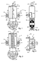
- la figure 1 est une vue de face, sur laquelle le ressort de rappel n'est pas représenté, d'une première variante de réalisation d'un tendeur selon la présente invention dans une condition compacte de stockage et de montage;
- la figure 2 est une vue de côté, avec arrachement partiel, du tendeur de la figure 1 dans une condition compacte de stockage et de montage;
- la figure 3 est une vue de face du tendeur de la figure 1 dans une condition précontrainte;
- la figure 4 est une vue de dessous du tendeur de la figure 1 dans une condition compacte de stockage et de montage;
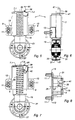
- la figure 5 est une vue de face, dans une condition compacte de stockage et de montage d'une deuxième variante de réalisation du tendeur selon la présente invention ;
- la figure 6 est une vue de côté, avec arrachement partiel du tendeur de la figure 5 dans une condition compacte de stockage ou de montage;
- la figure 7 est une vue de face du tendeur de la figure 5 dans une condition précontrainte;
- la figure 8 est une vue de dessus du tendeur de la figure 5 dans une condition compacte de stockage et de montage;
- la figure 9 est une vue de face d'une troisième variante de réalisation d'un tendeur selon la présente invention dans une condition compacte de montage ou de stockage;
- la figure 10 est une vue de côté, avec arrachement partiel, du tendeur de la figure 9, dans une condition compacte de stockage et de montage;
- la figure 11 est une vue de face, avec arrachement partiel, du tendeur de la figure 9 dans une condition précontrainte
- la figure 12 est une vue de dessus, avec arrachement partiel, du tendeur de la figure 9 dans une condition compacte de stockage et de montage;
- la figure 13 est une vue de face, avec arrachement partiel, de l'exemple préféré de réalisation d'un tendeur selon la présente invention dans une condition précontrainte ;
- la figure 14 est une vue de côté, avec arrachement partiel, du tendeur de la figure 13 dans une condition compacte de stockage et de montage;
- la figure 15 est une vue de dessus, avec arrachement partiel, du tendeur de la figure 13 dans une condition compacte de stockage et de montage.
Claims (15)
- Tendeur pour courroie (23) comportant:des moyens (21) d'appui sur une courroie (23) de transmission de mouvement;un élément d'ancrage (3, 13);un élément de rappel élastique (35) d'application des moyens d'appui (21) sur la courroie (23) de transmission de mouvement;
caractérisé en ce que l'élément d'ancrage (3) comporte une cage rigide de guidage en translation des moyens support (17,19) des moyens d'appui (21) sur la courroie (23) et en ce que l'élément de rappel élastique (35) est un élément interne à ladite cage rigide (3). - Tendeur selon la revendication 1, caractérisé en ce l'élément de rappel élastique (35) comporte un ressort hélicoïdal disposé à l'intérieur des moyens support (17) des moyens d'appui (21) sur la courroie (23).
- Tendeur selon la revendication 1 ou 2, caractérisé en ce que les axes de l'élément d'ancrage (3), de l'élément de rappel élastique (35) et des moyens support (17) guidés en translation par l'élément d'ancrage (3) sont confondus avec un axe (27) longitudinal du tendeur (1).
- Tendeur selon l'une quelconque des revendications précédentes, caractérisé en ce que l'élément d'ancrage (3) comporte des ouvertures (9) ou des oeillets de passage de boulons de fixation (11).
- Tendeur selon la revendication 4, caractérisé en ce que la cage (3) est réalisée en tôle métallique et en ce que les ouvertures (9) de passage de boulons (11) sont ménagées dans des pattes (13) réalisées en déployant la tôle de la cage (3) à partir de découpes (55) effectuées dans les parois latérales (57) de la cage (3).
- Tendeur selon l'une quelconque des revendications précédentes, caractérisé en ce qu'il comporte une couche (15) interposée entre la cage rigide (3) et les moyens support (17) pour assurer un guidage, et une friction procurant un amortissement du tendeur.
- Tendeur selon la revendication 6, caractérisé en ce que la couche (15) intermédiaire est réalisée en élastomère.
- Tendeur selon l'une quelconque des revendications précédentes, caractérisé en ce que la cage rigide (3) et les moyens support (17) ont une section sensiblement rectangulaire.
- Tendeur selon l'une quelconque des revendications précédentes, caractérisé en ce que les moyens d'appui (21) sur la courroie (23) comportent un galet.
- Tendeur selon l'une quelconque des revendications précédentes, caractérisé en ce qu'il comporte des moyens de verrouillage (39, 41, 42, 63, 65) dans une condition compacte de stockage et de montage dans laquelle l'élément de rappel élastique (35) est comprimé.
- Tendeur selon la revendication 10, caractérisé en ce que les moyens de verrouillage comportent un premier élément saillant (63) solidaire de la cage (3), un second élément saillant solidaire des moyens support (17) et une pièce amovible d'accouplement (41) de ces deux éléments saillants (63, 65).
- Tendeur selon la revendication 11, caractérisé en ce que les éléments saillants (63, 65) comportent des morceaux de tôle repliés de la cage (3) et de moyens support (17) et en ce que la pièce d'accouplement (41) est une goupille passant par des ouvertures (42) pratiquées dans lesdits éléments saillants.
- Tendeur selon l'une quelconque des revendications précédentes, caractérisé en ce qu'il comporte des moyens (61, 67) de limitation de la course des moyens support (17) des moyens d'appui (21) sur la courroie (23) pour les empêcher de sortir de la cage (3).
- Tendeur selon la revendication 13, caractérisé en ce que les moyens de limitation de la course comportent une avancée (67) en tôle de la cage (3) disposée sur le trajet d'un élément saillant (65) en tôle de moyens support (17) des moyens d'appui (21) sur la courroie (23).
- Tendeur selon l'une quelconque des revendications précédentes, caractérisé en ce que l'élément d'ancrage (13), les moyens support (17) et les moyens d'appui (21) sont coaxiaux.
Applications Claiming Priority (2)
| Application Number | Priority Date | Filing Date | Title |
|---|---|---|---|
| FR9900778 | 1999-01-25 | ||
| FR9900778A FR2788825B1 (fr) | 1999-01-25 | 1999-01-25 | Tendeur pour courroie, circuit cinematique et moteur comportant un tel tendeur |
Publications (2)
| Publication Number | Publication Date |
|---|---|
| EP1022488A1 true EP1022488A1 (fr) | 2000-07-26 |
| EP1022488B1 EP1022488B1 (fr) | 2005-12-07 |
Family
ID=9541186
Family Applications (1)
| Application Number | Title | Priority Date | Filing Date |
|---|---|---|---|
| EP00400073A Expired - Lifetime EP1022488B1 (fr) | 1999-01-25 | 2000-01-13 | Tendeur pour courroie, circuit cinématique et moteur comportant un tel tendeur |
Country Status (6)
| Country | Link |
|---|---|
| US (1) | US6422964B1 (fr) |
| EP (1) | EP1022488B1 (fr) |
| JP (1) | JP2000213607A (fr) |
| AT (1) | ATE312304T1 (fr) |
| DE (1) | DE60024507D1 (fr) |
| FR (1) | FR2788825B1 (fr) |
Cited By (3)
| Publication number | Priority date | Publication date | Assignee | Title |
|---|---|---|---|---|
| WO2002068842A1 (fr) * | 2001-02-20 | 2002-09-06 | The Gates Corporation | Tendeur lineaire |
| EP1688643A3 (fr) * | 2005-02-05 | 2007-09-19 | Schaeffler KG | Dispositif de tension linéaire |
| CN103335077A (zh) * | 2013-07-09 | 2013-10-02 | 刘胜 | 拖拉机皮带传动张紧装置 |
Families Citing this family (13)
| Publication number | Priority date | Publication date | Assignee | Title |
|---|---|---|---|---|
| DE10031610A1 (de) * | 2000-06-29 | 2002-02-07 | Schaeffler Waelzlager Ohg | Kettenspanner |
| TWI225539B (en) * | 2001-11-06 | 2004-12-21 | Gates Corp | Travel limited linear belt tensioner |
| US20030109343A1 (en) * | 2001-12-11 | 2003-06-12 | Lee Martinson | Drive belt stabilizer system |
| CA2524925A1 (fr) * | 2003-05-06 | 2004-11-18 | Litens Automotive | Tendeur lineaire |
| DE602005024256D1 (de) * | 2005-07-25 | 2010-12-02 | Morse Tec Europe Srl | Spanner für eine Steuerkette |
| TW200723848A (en) * | 2005-12-02 | 2007-06-16 | Primax Electronics Ltd | Belt tension adjusting device |
| DE102006039743A1 (de) * | 2006-08-24 | 2008-02-28 | Schaeffler Kg | Spanneinrichtung für ein Zugmittel, insbesondere einen Riemen oder eine Kette |
| US20090062046A1 (en) * | 2007-09-04 | 2009-03-05 | Robert Lindemann | Belt tensioner with adjustable slider plate and replaceable pulley |
| JP6659454B2 (ja) * | 2016-05-13 | 2020-03-04 | Ntn株式会社 | オートテンショナ |
| CN105864377A (zh) * | 2016-06-15 | 2016-08-17 | 刘银明 | 一种皮带张紧轮转动调节装置 |
| US11111987B2 (en) * | 2017-10-10 | 2021-09-07 | Mobile Climate Control, Corp. | Counterforce drive-belt system |
| US10683914B2 (en) | 2018-02-14 | 2020-06-16 | Gates Corporation | Tensioner |
| US20260117845A1 (en) * | 2023-10-20 | 2026-04-30 | The Timken Company | Tensioning apparatus |
Citations (7)
| Publication number | Priority date | Publication date | Assignee | Title |
|---|---|---|---|---|
| GB724522A (en) * | 1951-12-28 | 1955-02-23 | Renold Chains Ltd | Improvements in tensioners for chains, belts and the like |
| US4416648A (en) * | 1981-01-12 | 1983-11-22 | Dyneer Corporation | Belt tensioner |
| EP0210508A2 (fr) * | 1985-08-02 | 1987-02-04 | Hans Jürgen Stark | Tendeur pour entraînements à courroie et à chaîne |
| US4765444A (en) * | 1979-10-23 | 1988-08-23 | Fritz Bauer+Sohne OHG | Friction damper |
| US5004448A (en) * | 1988-12-29 | 1991-04-02 | Nhk Spring Co., Ltd. | Tensioner |
| US5073158A (en) * | 1989-08-01 | 1991-12-17 | Nhk Spring Co., Ltd. | Belt or chain tensioner for power transmitting system |
| US5601505A (en) * | 1994-09-12 | 1997-02-11 | Borg-Warner Automotive, K.K. | Hydraulic tensioner |
Family Cites Families (5)
| Publication number | Priority date | Publication date | Assignee | Title |
|---|---|---|---|---|
| DE523754C (de) * | 1931-04-27 | Fried Krupp Akt Ges | Einstellvorrichtung fuer die Spannrolle der Gleisbaender von Kraftfahrzeugen | |
| GB696586A (en) * | 1950-09-26 | 1953-09-02 | George Mattey Baigent | Improvements in or relating to spring-tensioned jockey pulleys or sprockets |
| JPH0432519Y2 (fr) * | 1986-05-24 | 1992-08-05 | ||
| US5246404A (en) * | 1989-04-28 | 1993-09-21 | Nhk Spring Company Limited | Unit tensioner |
| ATE238191T1 (de) * | 1995-10-13 | 2003-05-15 | Intertractor Gmbh | Vorrichtung zum spannen und abfedern des leitrades von kettenfahrzeugen |
-
1999
- 1999-01-25 FR FR9900778A patent/FR2788825B1/fr not_active Expired - Fee Related
-
2000
- 2000-01-13 AT AT00400073T patent/ATE312304T1/de not_active IP Right Cessation
- 2000-01-13 DE DE60024507T patent/DE60024507D1/de not_active Expired - Lifetime
- 2000-01-13 EP EP00400073A patent/EP1022488B1/fr not_active Expired - Lifetime
- 2000-01-24 US US09/489,766 patent/US6422964B1/en not_active Expired - Fee Related
- 2000-01-25 JP JP2000015689A patent/JP2000213607A/ja active Pending
Patent Citations (7)
| Publication number | Priority date | Publication date | Assignee | Title |
|---|---|---|---|---|
| GB724522A (en) * | 1951-12-28 | 1955-02-23 | Renold Chains Ltd | Improvements in tensioners for chains, belts and the like |
| US4765444A (en) * | 1979-10-23 | 1988-08-23 | Fritz Bauer+Sohne OHG | Friction damper |
| US4416648A (en) * | 1981-01-12 | 1983-11-22 | Dyneer Corporation | Belt tensioner |
| EP0210508A2 (fr) * | 1985-08-02 | 1987-02-04 | Hans Jürgen Stark | Tendeur pour entraînements à courroie et à chaîne |
| US5004448A (en) * | 1988-12-29 | 1991-04-02 | Nhk Spring Co., Ltd. | Tensioner |
| US5073158A (en) * | 1989-08-01 | 1991-12-17 | Nhk Spring Co., Ltd. | Belt or chain tensioner for power transmitting system |
| US5601505A (en) * | 1994-09-12 | 1997-02-11 | Borg-Warner Automotive, K.K. | Hydraulic tensioner |
Cited By (3)
| Publication number | Priority date | Publication date | Assignee | Title |
|---|---|---|---|---|
| WO2002068842A1 (fr) * | 2001-02-20 | 2002-09-06 | The Gates Corporation | Tendeur lineaire |
| EP1688643A3 (fr) * | 2005-02-05 | 2007-09-19 | Schaeffler KG | Dispositif de tension linéaire |
| CN103335077A (zh) * | 2013-07-09 | 2013-10-02 | 刘胜 | 拖拉机皮带传动张紧装置 |
Also Published As
| Publication number | Publication date |
|---|---|
| JP2000213607A (ja) | 2000-08-02 |
| US6422964B1 (en) | 2002-07-23 |
| FR2788825A1 (fr) | 2000-07-28 |
| EP1022488B1 (fr) | 2005-12-07 |
| ATE312304T1 (de) | 2005-12-15 |
| DE60024507D1 (de) | 2006-01-12 |
| FR2788825B1 (fr) | 2001-03-09 |
Similar Documents
| Publication | Publication Date | Title |
|---|---|---|
| EP1022488B1 (fr) | Tendeur pour courroie, circuit cinématique et moteur comportant un tel tendeur | |
| FR2566081A1 (fr) | Tendeur de courroie | |
| FR2712056A1 (fr) | Dispositif pour la mise sous tension d'une commande de distribution. | |
| FR2497900A1 (fr) | Dispositif de tension de courroie | |
| EP0560685B1 (fr) | Tendeur pour courroie et système de transmission comprenant un tel tendeur | |
| FR2709796A1 (fr) | Dispositif d'obturation monobloc à guide centreur lubrifié pour tube d'amortisseur hydraulique pressurisé. | |
| FR3080422A1 (fr) | Dispositif de poulie pour galet tendeur ou enrouleur | |
| WO2014083174A1 (fr) | Suiveur de came avec dispositif anti-rotation | |
| FR2497901A1 (fr) | Dispositif de tension de courroie | |
| FR2920851A1 (fr) | Dispositif de galet tendeur de courroie | |
| FR2987411A1 (fr) | Dispositif tendeur d'un element de traction et procede de montage d'un tel dispositif | |
| FR3086027A1 (fr) | Dispositif de poulie pour galet tendeur ou enrouleur | |
| WO2002097274A2 (fr) | Rotor pour pompe a palettes | |
| FR2958987A1 (fr) | Palier a amortissement hydraulique pour le montage d'un moteur | |
| EP0055162B1 (fr) | Dispositif de tension et de guidage pour chaîne ou courroie sans fin | |
| FR3038020A1 (fr) | Dispositif de poulie pour galet tendeur ou enrouleur | |
| FR2739668A1 (fr) | Dispositif perfectionne d'obturation a guide centreur lubrifie pour tube d'amortisseur hydraulique pressurise | |
| FR2663099A1 (fr) | Support elastique comportant une couche d'elastomere et deux pieces d'extremite, notamment pour moteur marin. | |
| EP3814655B1 (fr) | Tendeur de courroie | |
| FR2995648A1 (fr) | Dispositif tendeur d'un organe de traction et moteur equipe d'un organe de traction et d'un tel dispositif tendeur | |
| FR2966774A1 (fr) | Vehicule comportant un dispositif d'amortissement des oscillations d'un ressort de suspension et dispositif d'amortissement des oscillations correspondant | |
| EP1653072B1 (fr) | Carter de moteur à combustion interne | |
| EP1018448A1 (fr) | Dispositif de suspension d'un groupe motopropulseur dans la caisse d'un vehicule automobile | |
| FR3067782B1 (fr) | Procede d’assemblage de guides de chaine de distribution de moteur et systeme de guidage d’une chaine de distribution | |
| FR2917464A1 (fr) | Moteur a combustion interne comportant un dispositif de tension de chaine integre a la culasse |
Legal Events
| Date | Code | Title | Description |
|---|---|---|---|
| PUAI | Public reference made under article 153(3) epc to a published international application that has entered the european phase |
Free format text: ORIGINAL CODE: 0009012 |
|
| AK | Designated contracting states |
Kind code of ref document: A1 Designated state(s): AT BE CH CY DE DK ES FI FR GB GR IE IT LI LU MC NL PT SE |
|
| AX | Request for extension of the european patent |
Free format text: AL;LT;LV;MK;RO;SI |
|
| 17P | Request for examination filed |
Effective date: 20001205 |
|
| AKX | Designation fees paid |
Free format text: AT BE CH CY DE DK ES FI FR GB GR IE IT LI LU MC NL PT SE |
|
| 17Q | First examination report despatched |
Effective date: 20020603 |
|
| GRAP | Despatch of communication of intention to grant a patent |
Free format text: ORIGINAL CODE: EPIDOSNIGR1 |
|
| GRAS | Grant fee paid |
Free format text: ORIGINAL CODE: EPIDOSNIGR3 |
|
| GRAA | (expected) grant |
Free format text: ORIGINAL CODE: 0009210 |
|
| AK | Designated contracting states |
Kind code of ref document: B1 Designated state(s): AT BE CH CY DE DK ES FI FR GB GR IE IT LI LU MC NL PT SE |
|
| PG25 | Lapsed in a contracting state [announced via postgrant information from national office to epo] |
Ref country code: IT Free format text: LAPSE BECAUSE OF FAILURE TO SUBMIT A TRANSLATION OF THE DESCRIPTION OR TO PAY THE FEE WITHIN THE PRESCRIBED TIME-LIMIT;WARNING: LAPSES OF ITALIAN PATENTS WITH EFFECTIVE DATE BEFORE 2007 MAY HAVE OCCURRED AT ANY TIME BEFORE 2007. THE CORRECT EFFECTIVE DATE MAY BE DIFFERENT FROM THE ONE RECORDED. Effective date: 20051207 Ref country code: FI Free format text: LAPSE BECAUSE OF FAILURE TO SUBMIT A TRANSLATION OF THE DESCRIPTION OR TO PAY THE FEE WITHIN THE PRESCRIBED TIME-LIMIT Effective date: 20051207 Ref country code: AT Free format text: LAPSE BECAUSE OF FAILURE TO SUBMIT A TRANSLATION OF THE DESCRIPTION OR TO PAY THE FEE WITHIN THE PRESCRIBED TIME-LIMIT Effective date: 20051207 Ref country code: NL Free format text: LAPSE BECAUSE OF FAILURE TO SUBMIT A TRANSLATION OF THE DESCRIPTION OR TO PAY THE FEE WITHIN THE PRESCRIBED TIME-LIMIT Effective date: 20051207 Ref country code: GB Free format text: LAPSE BECAUSE OF FAILURE TO SUBMIT A TRANSLATION OF THE DESCRIPTION OR TO PAY THE FEE WITHIN THE PRESCRIBED TIME-LIMIT Effective date: 20051207 Ref country code: IE Free format text: LAPSE BECAUSE OF FAILURE TO SUBMIT A TRANSLATION OF THE DESCRIPTION OR TO PAY THE FEE WITHIN THE PRESCRIBED TIME-LIMIT Effective date: 20051207 |
|
| REG | Reference to a national code |
Ref country code: GB Ref legal event code: FG4D Free format text: NOT ENGLISH |
|
| REG | Reference to a national code |
Ref country code: CH Ref legal event code: EP |
|
| REG | Reference to a national code |
Ref country code: IE Ref legal event code: FG4D Free format text: LANGUAGE OF EP DOCUMENT: FRENCH |
|
| REF | Corresponds to: |
Ref document number: 60024507 Country of ref document: DE Date of ref document: 20060112 Kind code of ref document: P |
|
| PG25 | Lapsed in a contracting state [announced via postgrant information from national office to epo] |
Ref country code: BE Free format text: LAPSE BECAUSE OF NON-PAYMENT OF DUE FEES Effective date: 20060131 Ref country code: CH Free format text: LAPSE BECAUSE OF NON-PAYMENT OF DUE FEES Effective date: 20060131 Ref country code: LI Free format text: LAPSE BECAUSE OF NON-PAYMENT OF DUE FEES Effective date: 20060131 Ref country code: MC Free format text: LAPSE BECAUSE OF NON-PAYMENT OF DUE FEES Effective date: 20060131 Ref country code: LU Free format text: LAPSE BECAUSE OF NON-PAYMENT OF DUE FEES Effective date: 20060131 |
|
| PG25 | Lapsed in a contracting state [announced via postgrant information from national office to epo] |
Ref country code: GR Free format text: LAPSE BECAUSE OF FAILURE TO SUBMIT A TRANSLATION OF THE DESCRIPTION OR TO PAY THE FEE WITHIN THE PRESCRIBED TIME-LIMIT Effective date: 20060307 Ref country code: SE Free format text: LAPSE BECAUSE OF FAILURE TO SUBMIT A TRANSLATION OF THE DESCRIPTION OR TO PAY THE FEE WITHIN THE PRESCRIBED TIME-LIMIT Effective date: 20060307 Ref country code: DK Free format text: LAPSE BECAUSE OF FAILURE TO SUBMIT A TRANSLATION OF THE DESCRIPTION OR TO PAY THE FEE WITHIN THE PRESCRIBED TIME-LIMIT Effective date: 20060307 |
|
| PG25 | Lapsed in a contracting state [announced via postgrant information from national office to epo] |
Ref country code: DE Free format text: LAPSE BECAUSE OF FAILURE TO SUBMIT A TRANSLATION OF THE DESCRIPTION OR TO PAY THE FEE WITHIN THE PRESCRIBED TIME-LIMIT Effective date: 20060308 |
|
| PG25 | Lapsed in a contracting state [announced via postgrant information from national office to epo] |
Ref country code: ES Free format text: LAPSE BECAUSE OF FAILURE TO SUBMIT A TRANSLATION OF THE DESCRIPTION OR TO PAY THE FEE WITHIN THE PRESCRIBED TIME-LIMIT Effective date: 20060318 |
|
| PG25 | Lapsed in a contracting state [announced via postgrant information from national office to epo] |
Ref country code: PT Free format text: LAPSE BECAUSE OF FAILURE TO SUBMIT A TRANSLATION OF THE DESCRIPTION OR TO PAY THE FEE WITHIN THE PRESCRIBED TIME-LIMIT Effective date: 20060508 |
|
| NLV1 | Nl: lapsed or annulled due to failure to fulfill the requirements of art. 29p and 29m of the patents act | ||
| GBV | Gb: ep patent (uk) treated as always having been void in accordance with gb section 77(7)/1977 [no translation filed] |
Effective date: 20051207 |
|
| REG | Reference to a national code |
Ref country code: IE Ref legal event code: FD4D |
|
| REG | Reference to a national code |
Ref country code: CH Ref legal event code: PL |
|
| PLBE | No opposition filed within time limit |
Free format text: ORIGINAL CODE: 0009261 |
|
| STAA | Information on the status of an ep patent application or granted ep patent |
Free format text: STATUS: NO OPPOSITION FILED WITHIN TIME LIMIT |
|
| 26N | No opposition filed |
Effective date: 20060908 |
|
| BERE | Be: lapsed |
Owner name: HUTCHINSON Effective date: 20060131 |
|
| PG25 | Lapsed in a contracting state [announced via postgrant information from national office to epo] |
Ref country code: CY Free format text: LAPSE BECAUSE OF FAILURE TO SUBMIT A TRANSLATION OF THE DESCRIPTION OR TO PAY THE FEE WITHIN THE PRESCRIBED TIME-LIMIT Effective date: 20051207 |
|
| PGFP | Annual fee paid to national office [announced via postgrant information from national office to epo] |
Ref country code: FR Payment date: 20081127 Year of fee payment: 10 |
|
| REG | Reference to a national code |
Ref country code: FR Ref legal event code: ST Effective date: 20100930 |
|
| PG25 | Lapsed in a contracting state [announced via postgrant information from national office to epo] |
Ref country code: FR Free format text: LAPSE BECAUSE OF NON-PAYMENT OF DUE FEES Effective date: 20100201 |