EP1022204A2 - Trailer control valve for a pneumatic brake system of tractor-trailer combinations - Google Patents
Trailer control valve for a pneumatic brake system of tractor-trailer combinations Download PDFInfo
- Publication number
- EP1022204A2 EP1022204A2 EP99124900A EP99124900A EP1022204A2 EP 1022204 A2 EP1022204 A2 EP 1022204A2 EP 99124900 A EP99124900 A EP 99124900A EP 99124900 A EP99124900 A EP 99124900A EP 1022204 A2 EP1022204 A2 EP 1022204A2
- Authority
- EP
- European Patent Office
- Prior art keywords
- control
- valve
- chamber
- trailer
- piston
- Prior art date
- Legal status (The legal status is an assumption and is not a legal conclusion. Google has not performed a legal analysis and makes no representation as to the accuracy of the status listed.)
- Granted
Links
Images


Classifications
-
- B—PERFORMING OPERATIONS; TRANSPORTING
- B60—VEHICLES IN GENERAL
- B60T—VEHICLE BRAKE CONTROL SYSTEMS OR PARTS THEREOF; BRAKE CONTROL SYSTEMS OR PARTS THEREOF, IN GENERAL; ARRANGEMENT OF BRAKING ELEMENTS ON VEHICLES IN GENERAL; PORTABLE DEVICES FOR PREVENTING UNWANTED MOVEMENT OF VEHICLES; VEHICLE MODIFICATIONS TO FACILITATE COOLING OF BRAKES
- B60T13/00—Transmitting braking action from initiating means to ultimate brake actuator with power assistance or drive; Brake systems incorporating such transmitting means, e.g. air-pressure brake systems
- B60T13/10—Transmitting braking action from initiating means to ultimate brake actuator with power assistance or drive; Brake systems incorporating such transmitting means, e.g. air-pressure brake systems with fluid assistance, drive, or release
- B60T13/24—Transmitting braking action from initiating means to ultimate brake actuator with power assistance or drive; Brake systems incorporating such transmitting means, e.g. air-pressure brake systems with fluid assistance, drive, or release the fluid being gaseous
- B60T13/26—Compressed-air systems
- B60T13/261—Compressed-air systems systems with both indirect application and application by springs or weights and released by compressed air
- B60T13/263—Compressed-air systems systems with both indirect application and application by springs or weights and released by compressed air specially adapted for coupling with dependent systems, e.g. tractor-trailer systems
-
- B—PERFORMING OPERATIONS; TRANSPORTING
- B60—VEHICLES IN GENERAL
- B60T—VEHICLE BRAKE CONTROL SYSTEMS OR PARTS THEREOF; BRAKE CONTROL SYSTEMS OR PARTS THEREOF, IN GENERAL; ARRANGEMENT OF BRAKING ELEMENTS ON VEHICLES IN GENERAL; PORTABLE DEVICES FOR PREVENTING UNWANTED MOVEMENT OF VEHICLES; VEHICLE MODIFICATIONS TO FACILITATE COOLING OF BRAKES
- B60T13/00—Transmitting braking action from initiating means to ultimate brake actuator with power assistance or drive; Brake systems incorporating such transmitting means, e.g. air-pressure brake systems
- B60T13/10—Transmitting braking action from initiating means to ultimate brake actuator with power assistance or drive; Brake systems incorporating such transmitting means, e.g. air-pressure brake systems with fluid assistance, drive, or release
- B60T13/66—Electrical control in fluid-pressure brake systems
- B60T13/68—Electrical control in fluid-pressure brake systems by electrically-controlled valves
- B60T13/683—Electrical control in fluid-pressure brake systems by electrically-controlled valves in pneumatic systems or parts thereof
-
- B—PERFORMING OPERATIONS; TRANSPORTING
- B60—VEHICLES IN GENERAL
- B60T—VEHICLE BRAKE CONTROL SYSTEMS OR PARTS THEREOF; BRAKE CONTROL SYSTEMS OR PARTS THEREOF, IN GENERAL; ARRANGEMENT OF BRAKING ELEMENTS ON VEHICLES IN GENERAL; PORTABLE DEVICES FOR PREVENTING UNWANTED MOVEMENT OF VEHICLES; VEHICLE MODIFICATIONS TO FACILITATE COOLING OF BRAKES
- B60T15/00—Construction arrangement, or operation of valves incorporated in power brake systems and not covered by groups B60T11/00 or B60T13/00
- B60T15/02—Application and release valves
- B60T15/025—Electrically controlled valves
- B60T15/027—Electrically controlled valves in pneumatic systems
Definitions
- Trailer control valves are known from the prior art, which are installed in the towing vehicle and the brake system of the trailer with compressed air and during braking Taxes.
- the braking system of the trailer is through a supply line and a brake line with the trailer control valve of the Towing vehicle connected.
- the known trailer control valves include one double seat valve (inlet and outlet valve), two control pistons, three control chambers as well as a pantry and a working chamber.
- the three control chambers open and close the double seat valve, which aerates or vents the brake line.
- the three tax chambers are controlled by four control circuits, one electro-pneumatic Control circuit, a first pneumatic service brake circuit, a second pneumatic service brake circuit as well a parking brake circuit.
- the trailer control valve according to the invention has the advantage that in the first part of the retention chamber by means of Pressure signals from the electro-pneumatic control circuit have a retention force can be generated on the second control piston, which against it the double seat valve actuating movement acts.
- This can the modulated brake pressure in the primary, electro-pneumatic Control circuit can be adjusted to a low value without the subordinate, second pneumatic service brake circuit on the second Control piston responds.
- Such is a reduction in brake pressure especially with brake systems that include a coupling force control, advantageous. Due to the additional restraint, the Trailers with low braking pressure are braked.
- Fig.1 is a circuit diagram of an electrical and pneumatic controllable trailer control valve 1 according to a preferred Embodiment of the invention shown.
- the trailer control valve 1 is with a connection 2 to a compressed air supply and via electrical Control connections 4 to an electro-pneumatic control circuit connected to the tractor.
- the electro-pneumatic control circuit stands with the electrical part of a brake value transmitter, not shown or service brake valve of the service brake system of the Tractor in connection.
- the first control piston 38 has a central, tubular extension 44, which in a central opening of a second control piston 46 projecting longitudinally displaceably in an inner guide bushing 48 is stored.
- a radially outer pressure ring inner valve seat 50 of the double seat valve 16 is provided, which is arranged at the head end of the second control piston 46 is.
- the radially outer pressure ring 50 of the first control piston 38 forms together with a along a bearing bush 54 of the second control piston 46 longitudinally displaceably arranged valve body 56 an inner seat valve 58 (exhaust valve) of the double seat valve 16.
- In the closed position of the inner seat valve 58 is the Pressure ring 50 of the first control piston 38 against a valve plate 60 of the valve body 56 biased pressure-tight.
- the unregulated, second pneumatic service brake circuit with its higher control pressure p 18 can Unintentionally dub the leading electro-pneumatic control circuit with its lower control pressure p el by the higher control pressure p 18 in the third control chamber 90 pushing the second control piston 46 upward and opening the outer seat valve 64, as a result of which excessive brake pressure is built up in the brake line 26 .
- the pressure p el causes an upward force on the bottom of the sliding cup 78 in the inner part 92 of the retaining chamber 94 and a downward force on the first annular collar 82 of the sliding cup 78 in the outer part 96 of the retaining cup 94, the forces acting in the direction of displacement Areas of the displacement cup 78 and the first collar 82 of the displaceable body 74 are so large that these forces approximately compensate each other.
- the pressure p el additionally creates a downward force on the bottom of the control piston cup 84, which counteracts an upward force resulting from the pressure p 18 in the third control chamber 90.
Abstract
Description
Die Erfindung geht aus von einem Anhängersteuerventil für eine
Druckluftbremsanlage von Zugfahrzeug-Anhänger-Kombinationen nach
der Gattung des Patentanspruchs 1.The invention is based on a trailer control valve for one
Air brake system from tractor-trailer combinations
the genus of
Aus dem Stand der Technik sind Anhängersteuerventile bekannt, welche im Zugfahrzeug eingebaut sind und die Bremsanlage des Anhängers mit Druckluft versorgen sowie bei einer Bremsung steuern. Hierbei ist die Bremsanlage des Anhängers durch eine Vorratsleitung und eine Bremsleitung mit dem Anhängersteuerventil des Zugfahrzeugs verbunden. Die bekannten Anhängersteuerventile beinhalten je ein Doppelsitzventil (Ein-, Auslaßventil), zwei Steuerkolben, drei Steuerkammern sowie eine Vorratskammer und eine Arbeitskammer. Die drei Steuerkammern öffnen und schließen das Doppelsitzventil, welches die Bremsleitung be- oder entlüftet. Die drei Steuerkammern werden durch vier Steuerkreise angesteuert, einen elektro-pneumatischen Steuerkreis, einen ersten pneumatischen Betriebsbremskreis, einen zweiten pneumatischen Betriebsbremskreis sowie einen Feststellbremskreis. Beim Bremsen des Zugfahrzeugs durch Betätigen eines Bremswertgebers/Betriebsbremsventils werden sowohl der elektro-pneumatische Steuerkreis als auch die beiden pneumatischen Betriebsbremskreise mit Steuerdruck beaufschlagt. Der Feststellbremskreis steuert neben der Feststell-Bremsanlage des Zugfahrzeugs auch die Betriebs-Bremsanlage des Anhängers, die sowohl bei einer Betriebsbremsung als auch bei einer Feststellbremsung des Zugfahrzeugs mit Druck beaufschlagt wird.Trailer control valves are known from the prior art, which are installed in the towing vehicle and the brake system of the trailer with compressed air and during braking Taxes. Here the braking system of the trailer is through a supply line and a brake line with the trailer control valve of the Towing vehicle connected. The known trailer control valves include one double seat valve (inlet and outlet valve), two control pistons, three control chambers as well as a pantry and a working chamber. The three control chambers open and close the double seat valve, which aerates or vents the brake line. The three tax chambers are controlled by four control circuits, one electro-pneumatic Control circuit, a first pneumatic service brake circuit, a second pneumatic service brake circuit as well a parking brake circuit. When braking the towing vehicle Operating a brake value transmitter / service brake valve are both the electro-pneumatic control circuit as well as the two pneumatic ones Service brake circuits with control pressure. The parking brake circuit controls next to the parking brake system of the towing vehicle also the service braking system of the trailer, which both at a service braking as well as a parking brake of the Towing vehicle is pressurized.
Der elektro-pneumatische Steuerkreis weist ein in einen elektronischen Regelkreis integriertes elektronisches Steuergerät auf, wobei der elektronische Regelkreis zur stufenlosen Regelung des Bremsdrucks dient. Das elektronische Steuergerät steuert magnetbetätigte Ventile derart an, daß bei Betätigung der Bremse des Zugfahrzeugs Druckluft von einem Vorratsbehälter in eine erste Steuerkammer des Anhängersteuerventils strömen kann und einen ersten Steuerkolben gegen einen Ventilkörper des Doppelsitzventils drückt, worauf dieser von seinem Ventilsitz abhebt und Druckluft von der Vorratskammer in die Arbeitskammer und von dort in die Bremsleitung des Anhängers strömen läßt.The electro-pneumatic control circuit has an electronic one Control loop integrated electronic control unit, where the electronic control loop for the stepless regulation of the Brake pressure is used. The electronic control unit controls solenoid-operated Valves in such a way that when the brake of the towing vehicle is actuated Compressed air from a reservoir to a first control chamber of the trailer control valve can flow and a first control piston presses against a valve body of the double seat valve, whereupon this takes off from its valve seat and compressed air from the pantry into the working chamber and from there into the trailer's brake line can flow.
Bei Betätigen der Bremse des Zugfahrzeugs schaltet die Steuerelektronik außerdem ein elektromagnetisches Rückhaltventil in seine Sperrstellung, so daß der erste pneumatische Betriebsbremskreis, welcher ebenfalls an die erste Steuerkammer des Anhängersteuerventils angeschlossen ist, nicht wirksam werden kann. Das Bremssignal des elektro-pneumatischen Steuerkreises hat daher Vorrang vor dem Bremssignal des ersten pneumatischen Betriebsbremskreises. Erst bei Ausfall des führenden elektro-pneumatischen Steuerkreises übernimmt der nachrangige erste pneumatische Betriebsbremskreis die Steuerfunktion, indem das elektromagnetische Rückhaltventil in die stromlose Durchgangsstellung geschaltet wird.The control electronics switch when the towing vehicle brake is actuated also an electromagnetic check valve in its Locked position, so that the first pneumatic service brake circuit, which also to the first control chamber of the trailer control valve connected, cannot take effect. The brake signal of the electro-pneumatic control circuit therefore has priority over the Brake signal of the first pneumatic service brake circuit. Only at; only when Failure of the leading electro-pneumatic control circuit takes over the subordinate first pneumatic service brake circuit the control function, by putting the electromagnetic check valve into the de-energized Through position is switched.
Unabhängig von der Funktion des elektro-pneumatischen Steuerkreises ist die dritte Steuerkammer mit dem zweiten pneumatischen Betriebsbremskreis verbunden, dessen Drucksignale auf einen zweiten Steuerkolben des Anhängersteuerventils übertragen werden, welcher ebenfalls das Doppelsitzventil betätigen und dadurch die Bremsleitung des Anhängers mit Druckluft beaufschlagen kann.Regardless of the function of the electro-pneumatic control circuit is the third control chamber with the second pneumatic Service brake circuit connected, the pressure signals to a second Control piston of the trailer control valve are transmitted, which also operate the double seat valve and thereby the brake line can apply compressed air to the trailer.
Das bekannte Anhängersteuerventil hat den Nachteil, daß der zweite pneumatische Betriebsbremskreis den vorrangigen elektro-pneumatischen Steuerkreis überspielen kann, wenn der Druck im elektro-pneumatischen Steuerkreis aufgrund einer nur geringen Bremsdruckanforderung durch die elektronische Regelung zu niedrig ist, weil z.B. bei einer Regelung der Koppelkraft zwischen Zugfahrzeug und Anhänger der Bremsdruck der Anhängerbremsanlage vermindert wird. Dies würde zu einem unerwünschten Unwirksamwerden der elektronischen Regelung am Anhängersteuerventil führen.The known trailer control valve has the disadvantage that the second pneumatic service brake circuit the primary electro-pneumatic Control circuit can dub if the pressure in the electro-pneumatic Control circuit due to only a small Brake pressure requirement due to the electronic control too low is because e.g. when regulating the coupling force between the towing vehicle and trailer the brake pressure of the trailer brake system is reduced becomes. This would undesirably render the electronic ineffective Carry out regulation on the trailer control valve.
Das erfindungsgemäße Anhängersteuerventil hat demgegenüber den Vorteil, daß im ersten Teil der Rückhaltekammer mittels der Drucksignale des elektro-pneumatischen Steuerkreises eine Rückhaltekraft auf den zweiten Steuerkolben erzeugbar ist, welche gegen dessen das Doppelsitzventil betätigende Bewegung wirkt. Dadurch kann der modulierte Bremsdruck im vorrangigen, elektro-pneumatischen Steuerkreis auf einen niedrigen Wert eingeregelt werden, ohne daß der nachrangige, zweite pneumatische Betriebsbremskreis am zweiten Steuerkolben anspricht. Eine solche Reduzierung des Bremsdrucks ist gerade bei Bremssystemen, welche eine Koppelkraftregelung beinhalten, von Vorteil. Bedingt durch die zusätzliche Rückhaltung kann der Anhänger mit geringem Bremsdruck abgebremst werden.In contrast, the trailer control valve according to the invention has the advantage that in the first part of the retention chamber by means of Pressure signals from the electro-pneumatic control circuit have a retention force can be generated on the second control piston, which against it the double seat valve actuating movement acts. This can the modulated brake pressure in the primary, electro-pneumatic Control circuit can be adjusted to a low value without the subordinate, second pneumatic service brake circuit on the second Control piston responds. Such is a reduction in brake pressure especially with brake systems that include a coupling force control, advantageous. Due to the additional restraint, the Trailers with low braking pressure are braked.
Besonders vorteilhaft ist weiterhin, daß zwischen dem verschieblichen Körper und dem Ventilgehäuse ein zweiter Teil der Rückhaltekammer gebildet ist, in welcher eine der Rückhaltekraft entgegengerichtete und im wesentlichen gleich große Stützkraft auf den verschieblichen Körper erzeugbar ist. Da die Rückhaltekraft im ersten Teil der Rückhaltekammer nicht nur auf den zweiten Steuerkolben sondern auch auf den verschieblichen Körper selbst wirkt, verhindert die im zweiten Teil der Rückhaltekammer wirkende entgegengerichtete und sich am Ventilgehäuse abstützende Stützkraft, daß sich der verschiebliche Körper ungewollt verschiebt.It is also particularly advantageous that between the movable Body and the valve housing a second part of the containment chamber is formed, in which one of the restraining force opposes and essentially equal support force on the sliding Body can be generated. Because the retention force in the first part the retention chamber not only on the second control piston but also acts on the movable body itself, prevents the im second part of the retention chamber acting opposite and supporting force on the valve housing, that the displaceable Body shifted unintentionally.
Weitere Vorteile ergeben sich daraus, daß der verschiebliche Körper bei Druckabfall in der Vorratskammer durch die Drucksignale in der zweiten Steuerkammer derart verschiebbar ist, daß er auf den zweiten Steuerkolben eine Mitnahmekraft erzeugt, welche die das Doppelsitzventil betätigende Bewegung des zweiten Steuerkolbens unterstützt. Hierdurch kann bei Abfall des Vorratsdrucks der zweite Steuerkolben schneller auf ein Bremsdruckanforderungssignal des zweiten pneumatischen Betriebsbremskreises ansprechen.Further advantages result from the fact that the movable Body in case of pressure drop in the storage chamber by the pressure signals in the second control chamber is displaceable so that it on the second control piston generates a driving force, which the Double seat valve actuating movement of the second control piston supported. As a result, the second can drop when the supply pressure drops Control piston faster to a brake pressure request signal from the respond to the second pneumatic service brake circuit.
Durch die in den Unteransprüchen aufgeführten Maßnahmen
sind vorteilhafte Weiterbildungen und Verbesserungen des im Patentanspruch
1 angegebenen Anhängersteuerventils möglich.By the measures listed in the subclaims
are advantageous developments and improvements in the
Besonders zu bevorzugende Ausgestaltungen sehen vor, daß der zweite Steuerkolben einen fußseitigen Kolbenzapfen aufweist, entlang dessen der verschiebliche Körper mittels einer mittigen Durchgangsbohrung aufgenommen ist und daß die vom verschieblichen Körper auf den zweiten Steuerkolben erzeugbare Mitnahmekraft durch einen Anschlag am Kolbenzapfen übertragbar ist. Da das gattungsbildende Anhängersteuerventil ebenfalls einen fußseitigen Kolbenzapfen aufweist, sind durch diese Maßnahmen bei bereits bestehenden Anhängersteuerventilen keine tiefgreifenden konstruktiven Änderungen notwendig, um einen verschieblichen Körper gemäß der Erfindung vorzusehen.Particularly preferred configurations provide that the second control piston has a piston pin on the foot side, along which the displaceable body by means of a central through hole is recorded and that of the movable body driving force that can be generated on the second control piston by a Stop on the piston pin is transferable. Since the generic Trailer control valve also a piston pin on the foot side has through these measures with existing trailer control valves no profound constructive changes necessary to provide a slidable body according to the invention.
Ausführungsbeispiele der Erfindung sind in den Zeichnungen
dargestellt und in der nachfolgenden Beschreibung näher erläutert. Es
zeigen :
In Fig.1 ist ein Schaltschema eines elektrisch und pneumatisch
ansteuerbaren Anhängersteuerventils 1 gemäß einer bevorzugten
Ausführungsform der Erfindung dargestellt. Das Anhängersteuerventil
1 ist mit einem Anschluß 2 an einen Druckluftvorrat und über elektrische
Steueranschlüsse 4 an einen elektro-pneumatischen Steuerkreis
der Zugmaschine angeschlossen. Der elektro-pneumatische Steuerkreis
steht mit dem elektrischen Teil eines nicht dargestellten Bremswertgebers
oder Betriebsbremsventils der Betriebsbremsanlage der
Zugmaschine in Verbindung.In Fig.1 is a circuit diagram of an electrical and pneumatic
controllable
Das Anhängersteuerventil 1 weist ein elektronisches Steuergerät
6 auf, welches über Signalleitungen ein Rückhaltventil RV, ein Einlaßventil
EV und ein Auslaßventil AV ansteuert. Das Einlaßventil EV und
das Auslaßventil AV sind als elektromagnetbetätigte 2/2-Wegeventile
mit stromloser Sperrstellung ausgebildet, wobei das Einlaßventil EV
zuströmseitig mit dem Vorratsluftanschluß 2 und abströmseitig mit einer
in Fig.1 schematisch als Betätigungsmittel dargestellten, ersten
Steuerkammer 8 des Anhängersteuerventils 1 verbunden ist, während
das Auslaßventil AV zuströmseitig mit der ersten Steuerkammer 8 und
abströmseitig mit einem als Geräuschdämpfer 10 ausgebildeten Entlüftungsauslaß
verbunden ist. Im weiteren zweigt von der Zuströmseite
des Einlaßventils EV eine Drosselleitung mit einem Drosselventil DV
ab.The
Das Anhängersteuerventil 1 umfaßt im weiteren ein Doppelsitzventil
16 (Ein- und Auslaßventil), welches über einen pneumatischen
Steueranschluß 20 vom ersten pneumatischen Betriebsbremskreis und
über einen weiteren pneumatischen Steueranschluß 18 von einem
zweiten pneumatischen Betriebsbremskreis der Zugmaschine ansteuerbar
ist. Das vom elektronischen Steuergerät 6 schaltbare, elektromagnetbetätigte
Rückhaltventil RV steht zuströmseitig mit dem pneumatischen
Steueranschluß 20 und abströmseitig mit der ersten Steuerkammer
8 in Verbindung, über welche das Doppelsitzventil 16 des
Anhängersteuerventils 1 durch Druckaufbau im Bremssinn schaltbar
ist. Das Doppelsitzventil 16 ist im weiteren auch über den pneumatischen
Steueranschluß 18 durch Druckaufbau im Bremsinn schaltbar.
Die Steueranschlüsse 18, 20 erhalten die Bremsdrucksignale von dem
nicht dargestellten Betriebsbremsventil der Zugmaschine.The
Ein erster Ausgang 24 des Doppelsitzventils 16 ist mit einer
Bremsleitung 26 des Anhängers, ein zweiter Eingang 28 mit dessen
Vorratsleitung 14 sowie dem Vorratsanschluß 2 und ein zweiter Ausgang
30 mit dem Entlüftungsauslaß 10 verbunden. Über einen Drucksensor
32 werden der Druck in der Bremsleitung 26 des Anhängers
gemessen und die Signale an das elektronische Steuergerät 6 übertragen,
welches zusammen mit dem Drucksensor 32 in eine Regeleinrichtung
zur Regelung des Bremsdrucks innerhalb des elektro-pneumatischen
Steuerkreises integriert ist.A
Bei wirksamer Steuerung durch den elektro-pneumatischen
Steuerkreis nimmt das Rückhaltventil RV seine bestromte Sperrstellung
ein, wodurch die Verbindung zwischen dem pneumatischen Steueranschluß
20 des zweiten pneumatischen Betriebsbremskreises und
der ersten Steuerkammer 8 des Anhängersteuerventils 1 unterbrochen
ist. Demgegenüber nimmt das Rückhaltventil RV bei ausgefallenem
elektro-pneumatischem Steuerkreis oder bei ausgefallenem elektronischem
Steuergerät seine stromlose Durchgangsstellung ein und ermöglicht
somit die Verbindung der ersten Steuerkammer 8 mit dem
zweiten pneumatischen Betriebsbremskreis über den pneumatischen
Steueranschluß 20. Schließlich ist das Doppelsitzventil 16 über einen
mit einem pneumatischen Feststellbremskreis in Verbindung stehenden
pneumatischen Steueranschluß 34 durch Druckabbau im
Bremssinn schaltbar.With effective control by the electro-pneumatic
Control circuit, the RV check valve takes its energized blocking position
a, which creates the connection between the
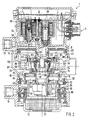
Die konstruktive Ausgestaltung des Anhängersteuerventils 1
gemäß der Erfindung ist in Fig.2 mittels eines Längsschnitts veranschaulicht.
Das Drosselventil DV von Fig.1 ist nicht erfindungswesentlich
und deshalb in Fig.2 nicht dargestellt. Gemäß Fig.2 sind in einem
Ventilgehäuse 36 kopfseitig das Rückhaltventil RV, das Auslaßventil
AV und das in dieser Ansicht nicht dargestellte Einlaßventil EV angeordnet.
Darüber hinaus ist im Kopfbereich auch das elektronische
Steuergerät 6 untergebracht, welches durch die elektrischen Steueranschlüsse
4 mit dem elektro-pneumatischen Steuerkreis der Zugmaschine
verbunden ist. Vom Ventilgehäuse 36 und einem ersten Steuerkolben
38 wird die erste Steuerkammer 8 des Anhängersteuerventils
1 begrenzt. Im oberen Teil des Anhängersteuerventils 1 ebenfalls zu
erkennen ist der pneumatische Steueranschluß 20 des ersten pneumatischen
Betriebsbremskreises, welcher über das Rückhalteventil RV
mit der ersten Steuerkammer 8 verbunden ist.The design of the
Der erste Steuerkolben 38 ist innerhalb des Ventilgehäuses 36
entlang dessen Längsachse verschieblich. Dichtungen 40 an seinem
radial äußeren Rand sorgen für eine druckdichte Abdichtung der ersten
Steuerkammer 8 gegenüber einer Arbeitskammer 42, welche sich
in Längsrichtung des Ventilgehäuses 36 gesehen der ersten Steuerkammer
8 anschließt. Die Arbeitskammer 42 ist über einen nicht dargestellten
Anschluß mit der Bremsleitung 26 des Anhängers verbunden.The
Der erste Steuerkolben 38 hat einen mittigen, rohrförmigen Fortsatz
44, welcher in eine mittige Öffnung eines zweiten Steuerkolbens
46 ragend in einer inneren Führungsbuchse 48 längsverschieblich
gelagert ist. Am Fortsatz 44 ist ein als radial äußerer Druckring ausgebildeter
innerer Ventilsitz 50 des Doppelsitzventils 16 vorgesehen,
welches am kopfseitigen Ende des zweiten Steuerkolbens 46 angeordnet
ist. Der radial äußere Druckring 50 des ersten Steuerkolbens
38 bildet zusammen mit einem entlang einer Lagerbuchse 54 des
zweiten Steuerkolbens 46 längsverschieblich angeordneten Ventilkörper
56 ein inneres Sitzventil 58 (Auslaßventil) des Doppelsitzventils
16. In der geschlossenen Stellung des inneren Sitzventils 58 ist der
Druckring 50 des ersten Steuerkolbens 38 gegen einen Ventilteller 60
des Ventilkörpers 56 druckdicht vorgespannt.The
Der zweite Steuerkolben 46 hat einen als radial inneren Druckring
ausgebildeten äußeren Ventilsitz 62, welcher den inneren Ventilsitz
50 umschließt und zusammen mit dem Ventilkörper 56 ein äußeres
Sitzventil 64 (Einlaßventil) des Doppelsitzventils 16 bildet. Der Ventilkörper
56 ist mit seinem Ventilteller 60 durch den Druck einer im
zweiten Steuerkolben 46 versenkt angeordneten Ventildruckfeder 66
gegen den inneren und den äußeren Ventilsitz 50, 62 vorgespannt.The
Entlang des Umfangs der den Ventilkörper 56 umschließenden
Wand des zweiten Steuerkolbens sind Rippen 68 vorgesehen, durch
deren Umfangszwischenräume eine Verbindung zwischen einer den
Kopfbereich des zweiten Steuerkolbens 46 umschließenden Vorratskammer
70 und dem Doppelsitzventil 16 geschaffen ist. Die Vorratskammer
70 ist gemäß Fig.1 durch den Anschluß 2 an den Druckluftvorrat
des elektro-pneumatischen Steuerkreises der Zugmaschine angeschlossen
und steht unter einem Druck p2.Along the circumference of the wall of the second control piston surrounding the
An das Doppelsitzventil 16 schließt sich ein entlang eines fußseitigen
Kolbenzapfens 72 des zweiten Steuerkolbens 46 längsverschieblicher
Körper 74 an, dessen Verschieblichkeit in Richtung auf
die Vorratskammer 70 durch einen als Absatz am zweiten Steuerkolben
46 ausgebildeten Anschlag 76 nach oben hin begrenzt ist. Der
verschiebliche Körper 74 hat vorzugsweise einen Verschiebebecher
78 mit einer mittigen Durchgangsbohrung 80 für die Führung längs des
Kolbenzapfens 72 und im weiteren einen von der Becherwand nach
radial außen wegragenden ersten Ringbund 82. The
Auf das Ende des Kolbenzapfens 72 ist ein Steuerkolbenbecher
84 mittels einer Mutter gespannt, welcher mit einem zweiten, radial
äußeren Ringbund 86 versehen ist, wobei einerseits zwischen dem
zweiten Ringbund 86 des Steuerkolbenbechers 84, dem ersten Ringbund
82 des Verschiebebechers 78 und dem Ventilgehäuse 36 eine
zweite Steuerkammer 88 und andererseits zwischen dem zweiten
Ringbund 86 des zweiten Steuerkolbens 46 und dem Ventilgehäuse 36
eine dritte Steuerkammer 90 gebildet ist. Die zweite Steuerkammer 88
ist über einen nicht dargestellten Kanal mit dem pneumatischen Steueranschluß
34 des Feststellbremskreises verbunden (s. Fig.1) und
steht unter einem Druck p34. Die dritte Steuerkammer 90 ist mit dem
pneumatischen Steueranschluß 18 des zweiten pneumatischen Betriebsbremskreises
verbunden und steht unter einem Druck p18.At the end of the
Der verschiebliche Körper 74 umgreift mit der Becherwand seines
Verschiebebechers 78 den Steuerkolbenbecher 84 im Bereich
dessen Bodens und ist hierdurch zusätzlich geführt. Zwischen dem
Boden des Verschiebebechers 78 und dem Boden des Steuerkolbenbechers
84 ist ein innerer Teil 92 einer Rückhaltekammer 94 sowie
zwischen dem ersten Ringbund 82 des Verschiebebechers 78 und
dem Ventilgehäuse 36 ein äußerer Teil 96 der Rückhaltekammer 94
gebildet. Der innere und äußere Teil 92, 96 der Rückhaltekammer 94
stehen mittels Durchgänge 95 in der Becherwand des Verschiebebechers
78 miteinander in Verbindung. Zusätzlich ist zwischen der ersten
Steuerkammer 8 und der Rückhaltekammer 94 ein Verbindungskanal
97 im Gehäuse 36 vorgesehen, welcher in der Schnittansicht gemäß
Fig.2 vereinfacht als außenliegendes Rohr angedeutet ist. Der zweite
Steuerkolben 46 ist an mehreren Stellen innerhalb des Ventilgehäuses
36 längsverschieblich geführt, wobei durch Dichtungen 98 sichergestellt
ist, daß keine Druckluft aus einer der von ihm begrenzten Kammern
entweichen kann. Ebenso ist der verschiebliche Körper 74 mit
solchen Dichtungen 98 versehen. Der Kolbenzapfen 72 des zweiten
Steuerkolbens 46 ist als Rohr ausgebildet, welches die über Entlüftungsschlitze
100 im zweiten Steuerkolben 46 vom inneren Sitzventil
58 (Auslaßventil) abgelassene Druckluft dem Geräuschdämpfer 10 am
Boden des Ventilgehäuses 36 zuführt, von wo aus diese in die Umgebung
austritt.The
Das Anhängersteuerventil 1, in dessen Vorratskammer 70 und
Steuerkammer 88 Vorratsdruck ansteht, hat im Zusammenwirken mit
der Betriebsbremsanlage der Zugmaschine bei einer Bremsung folgende
Funktionsweise:The
Bei Betätigen der Betriebsbremse der Zugmaschine erhält das
elektronische Steuergerät 6 vom elektrischen Teil des Betriebsbremsventils
über die elektrischen Steueranschlüsse 4 ein elektrisches
Bremsdruckanforderungssignal. Mit Auftreten dieses Signals schaltet
das elektronische Steuergerät 6 das Rückhaltventil RV in Sperrstellung,
so daß ein über den ersten pneumatischen Betriebsbremskreis
am pneumatischen Steueranschluß 20 herangeführtes pneumatisches
Bremsdruckanforderungssignal des Betriebsbremsventils nicht wirksam
werden kann. Das an den elektrischen Steueranschlüssen 4 herrschende
Signal des elektro-pneumatischen Steuerkreises hat daher
Vorrang vor dem Signal des ersten pneumatischen Betriebsbremskreises.
Das elektronische Steuergerät 6 moduliert die Signale an den
elektrischen Steueranschlüssen 4 wie folgt: Für Druckaufbau in der
ersten Steuerkammer 8 des Anhängersteuerventils 1 wird das Einlaßventil
EV durch das elektronische Steuergerät 6 eine bestimmte Zeit
lang in seine Durchgangsstellung geschaltet, während das Auslaßventil
AV in seiner Sperrstellung verbleibt. Abhängig von der Öffnungszeit
des Einlaßventils EV ensteht in der ersten Steuerkammer 8
ein Steuerdruck pel. Hierdurch wird der erste Steuerkolben 38 zusammen
mit dem an seinem Fortsatz 44 anliegenden Ventilkörper 56 gegen
die Vorspannung der Ventildruckfeder 66 nach unten gedrückt und
der Ventilkörper 56 vom äußeren Ventilsitz 62 abgehoben. Daraufhin
kann Druckluft von der Vorratskammer 70 durch die Rippen 68 des
zweiten Steuerkolbens 46 und durch das nun geöffnete äußere Sitzventil
64 (Einlaßventil) in die Arbeitskammer 42 und von dort in die
Bremsleitung 26 des Anhängers strömen. In der Arbeitskammer
herrscht dann ein Druck p42. Für Druckhalten wird das Einlaßventil EV
in seine Sperrstellung umgeschaltet. Für Druckabbau bleibt das Einlaßventil
EV in seiner Sperrstellung, während das Auslaßventil AV in
seine Durchlaßstellung geschaltet wird, wodurch der in der ersten
Steuerkammer 8 vorhandene Druck sinkt und der erste Steuerkolben
38 durch den höheren Druck in der Arbeitskammer 42 vom inneren
Ventilsitz 50 abhebt. Dann kann die Druckluft in der Arbeitskammer 42
durch das nun geöffnete innere Sitzventil 58 (Auslaßventil), durch die
Entlüftungsschlitze 100 und den rohrförmigen Kolbenzapfen 72 hindurch
über den Geräuschdämpfer 10 ins Freie treten.When the service brake of the tractor is actuated, the
Ist der führende elektro-pneumatische Steuerkreis gestört, nehmen
das Einlaßventil EV und das Auslaßventil AV stromlos ihre
Sperrstellungen und das Rückhaltventil RV seine stromlose Durchgangsstellung
ein. Ein vom ersten pneumatischen Betriebsbremskreis
über den pneumatischen Steueranschluß 20 herangeführtes
Bremsdruckanforderungssignal wird dann über das durchlässige
Rückhalteventil RV in die erste Steuerkammer 8 geleitet, um dort über
einen Steuerdruck p20 diesselbe Wirkung zu erzeugen wie vorangehend
beschrieben.If the leading electro-pneumatic control circuit is disturbed, the inlet valve EV and the outlet valve AV are de-energized in their blocking positions and the check valve RV is in its de-energized through position. A brake pressure request signal which is brought in from the first pneumatic service brake circuit via the
Bei Betätigung der Betriebsbremse der Zugmaschine liegt auch
am pneumatischen Steueranschluß 18 das pneumatische
Bremsdruckanforderungssignal des zweiten pneumatischen Betriebsbremskreises
an. Bei intaktem Anhängersteuerventil 1 und ohne Koppelkraftregelung
hat der Steuerdruck in der dritten Steuerkammer 90
des zweiten pneumatischen Betriebsbremskreises keine Schaltbewegung
des Steuerkolbens 46 zur Folge. Wird aber durch die Regeleinrichtung
des elektro-pneumatischen Steuerkreises ein niedriger Steuerdruck
pel in die erste Steuerkammer 8 eingesteuert, z.B. weil wegen
einer Koppelkraftregelung des Anhängers nur leicht abgebremst werden
soll, so kann der ungeregelte, zweite pneumatische Betriebsbremskreis
mit seinem höheren Steuerdruck p18 den führenden elektro-pneumatischen
Steuerkreis mit dessen niedrigerem Steuerdruck pel
ungewollt überspielen, indem der höhere Steuerdruck p18 in der dritten
Steuerkammer 90 den zweiten Steuerkolben 46 nach oben drängt und
das äußere Sitzventil 64 öffnet, wodurch ein zu hoher Bremsdruck in
der Bremsleitung 26 aufgebaut wird. Dies würde aber in unerwünschter
Weise zur Wirkungslosigkeit der elektronischen Regelung führen.When the service brake of the tractor is actuated, the pneumatic brake pressure request signal of the second pneumatic service brake circuit is also present at the
Erfindungsgemäß sind deshalb der verschiebliche Körper 74
und die Rückhaltekammer 94 vorgesehen, in welcher bedingt durch
den Verbindungskanal 97 derselbe Druck pel wie in der ersten Steuerkammer
8 vorherrscht. Wie aus der schematischen Darstellung von
Fig.3 hervorgeht, wird der verschiebliche Körper mit p34, p2 und pel beaufschlagt.
Der Druck pel verursacht im inneren Teil 92 der Rückhaltekammer
94 eine nach oben wirkende Kraft auf den Boden des Verschiebebechers
78 und im äußeren Teil 96 der Rückhaltekammer 94
eine nach unten wirkende Kraft auf den ersten Ringbund 82 des Verschiebebechers
78, wobei die in Verschieberichtung wirksamen Flächen
des Verschiebebechers 78 und des ersten Ringbundes 82 des
verschieblichen Körpers 74 derart groß sind, daß sich diese Kräfte annährend
kompensieren. According to the invention, therefore, the
Darüber hinaus entsteht durch den Druck pel zusätzlich eine
nach unten gerichtete Kraft auf den Boden des Steuerkolbenbechers
84, welche einer aus dem Druck p18 in der dritten Steuerkammer 90
herrührenden und nach oben gerichteten Kraft entgegenwirkt. Je größer
die aus pel hervorgehende Kraft auf den Steuerkolbenbecher 84
des zweiten Steuerkolbens 46 ist, umso mehr wird dieser zurückgehalten.
Bei intaktem elektrischem Steuerkreis sorgt die Rückhaltekammer
94 daher für eine Zurückhaltung des zweiten Steuerkolbens 46.In addition, the pressure p el additionally creates a downward force on the bottom of the
In Fig.4 ist die lineare Abhängigkeit des Drucks p42 in der
Bremsleitung über den Drücken p18 und p20 in dem zweiten und dem
ersten pneumatischen Betriebsbremskreis dargestellt. Die Linie A gibt
den Druckverlauf von p42 in Abhängigkeit von p20 und Linie B den
Druckverlauf von p42 in Abhängigkeit von p18 bei intaktem elektro-pneuma-tischem
Steuerkreis und bei Vorhandensein einer Rückhaltekammer
94 gemäß der Erfindung an. Wie zu sehen, ist der Druckverlauf
gemäß Linie B bedingt durch die Zurückhaltung des zweiten Steuerkolbens
46 relativ flach, was bedeutet, daß eine große Druckänderung
von p18 eine nur geringe Druckänderung von p42 in der Bremsleitung
des Anhängers hervorruft. Damit hat der zweite pneumatische
Betriebsbremskreis bei intaktem elektro-pneumatischem Steuerkreis
einen geringeren Einfluß auf den Bremsdruck p42 in der Bremsleitung
26 des Anhängers und kann den führenden elektro-pneumatischen
Steuerkreis nicht mehr überspielen.4 shows the linear dependence of the pressure p 42 in the brake line over the pressures p 18 and p 20 in the second and the first pneumatic service brake circuit. Line A gives the pressure curve of p 42 as a function of p 20 and line B the pressure curve of p 42 as a function of p 18 with an intact electro-pneumatic control circuit and with the presence of a
Bei Ausfall des elektro-pneumatischen Steuerkreises und des
ersten pneumatischen Betriebsbremskreises können keine Drücke pel
und p20 mehr in der Rückhaltekammer 94 wirken, so daß die Rückhaltekraft
auf den zweiten Steuerkolben 46 entfällt. Dadurch kann sich der
zweite Steuerkolben 46 aufgrund des Drucks p18 in der dritten Steuerkammer
90 leichter nach oben bewegen und das äußere Sitzventil 64
(Einlaßventil) öffnen. Dies hat zur Folge, daß dann der Druckverlauf
von p42 steiler und eine genügend größe Bremswirkung im Anhänger
erzeugt wird, wie durch die Linie C im Diagramm von Fig.4 dargestellt
ist.If the electro-pneumatic control circuit and the first pneumatic service brake circuit fail, pressures p el and p 20 can no longer act in the
Wie aus Fig.3 in anschaulicher Weise hervorgeht, wird bei ausgefallenem
elektro-pneumatischem Steuerkreis der verschiebliche
Körper 74 von unten durch den Druck p34 und von oben durch den
Druck p2 beaufschlagt, während der Druck pel in der Rückhaltekammer
94 gering ist. Bei einem Abfall des Vorratsdrucks sinkt der Druck p2 in
der Vorratskammer 70 gegenüber dem Druck in der zweiten Steuerkammer
88 ab, wodurch die auf eine obere Kolbenwand 102 des
zweiten Steuerkolbens 46 wirkende Kraft kleiner wird. Zwar ist der auf
den zweiten Ringbund 86 des zweiten Steuerkolbens 46 von oben wirkende
Druck p34 ebenfalls vom Druckvorrat abgezweigt, die zweite
Steuerkammer 88 ist aber über ein nicht dargestelltes Rückschlagventil
gegen Druckverlust abgesichert. Damit herrscht in der zweiten
Steuerkammer 88 ein relativ hoher Druck p34, welcher einerseits den
zweiten Steuerkolben 46 zurückhält und andererseits eine hohe, nach
oben gerichtete Kraft auf den verschieblichen Körper 74 ausübt. Im
weiteren wirkt auf den verschieblichen Körper 74 eine geringe, nach
unten gerichtete Kraft aufgrund des niedrigeren Drucks p2 in der Vorratskammer
70, weshalb sich eine resultierende Kraft nach oben ergibt,
welche den verschiebbaren Körper 74 nach oben gegen den Anschlag
76 am zweiten Steuerkolben 46 drückt. Hierdurch wird die
durch den Druck p18 in der dritten Steuerkammer 90 verursachte und
nach oben gerichtete Kraft auf den zweiten Steuerkolben 46 verstärkt
und die geringere Kraft auf die obere Kolbenwand 102 des zweiten
Steuerkolbens 46 kompensiert. Damit kann das äußere Sitzventil 64
(Einlaßventil) durch den sich nach oben bewegenden zweiten Steuerkolben
46 öffnen und das Bremsdruckanforderungssignal des zweiten
pneumatischen Betriebsbremskreises am Anschluß 18 schneller in einen
entsprechenden Bremsdruck in der Bremsleitung 26 umgesetzt
werden.As can be seen clearly from FIG. 3, if the electro-pneumatic control circuit fails, the
Claims (11)
Applications Claiming Priority (2)
| Application Number | Priority Date | Filing Date | Title |
|---|---|---|---|
| DE19902225A DE19902225A1 (en) | 1999-01-21 | 1999-01-21 | Trailer control valve for an air brake system of tractor-trailer combinations |
| DE19902225 | 1999-01-21 |
Publications (3)
| Publication Number | Publication Date |
|---|---|
| EP1022204A2 true EP1022204A2 (en) | 2000-07-26 |
| EP1022204A3 EP1022204A3 (en) | 2001-09-05 |
| EP1022204B1 EP1022204B1 (en) | 2004-03-24 |
Family
ID=7894911
Family Applications (1)
| Application Number | Title | Priority Date | Filing Date |
|---|---|---|---|
| EP99124900A Expired - Lifetime EP1022204B1 (en) | 1999-01-21 | 1999-12-17 | Trailer control valve for a pneumatic brake system of tractor-trailer combinations |
Country Status (4)
| Country | Link |
|---|---|
| EP (1) | EP1022204B1 (en) |
| AT (1) | ATE262434T1 (en) |
| DE (2) | DE19902225A1 (en) |
| TR (1) | TR200000236A2 (en) |
Cited By (15)
| Publication number | Priority date | Publication date | Assignee | Title |
|---|---|---|---|---|
| EP1127764A2 (en) * | 2000-02-26 | 2001-08-29 | WABCO GmbH & CO. OHG | Construction of a brake pressure modulator for a trailer with electronic braking system |
| WO2002087948A1 (en) * | 2001-04-26 | 2002-11-07 | Knorr-Bremse Systeme für Nutzfahrzeuge GmbH | Piloted valve comprising a pressure compensation channel |
| WO2002087947A1 (en) * | 2001-04-26 | 2002-11-07 | Knorr-Bremse Systeme für Nutzfahrzeuge GmbH | Electropneumatic control valve comprising a guide arrangement for a control piston |
| WO2002087938A2 (en) * | 2001-04-26 | 2002-11-07 | Knorr-Bremse | Electropneumatic control valve with a seal arrangement |
| EP1780087A1 (en) * | 2005-10-28 | 2007-05-02 | KNORR-BREMSE SYSTEME FÜR NUTZFAHRZEUGE GmbH | Electro-pneumatic trailer brake valve |
| WO2008138641A2 (en) * | 2007-05-16 | 2008-11-20 | Knorr-Bremse Systeme für Nutzfahrzeuge GmbH | Braking system for a utility vehicle that can be pneumatically coupled to a trailer, and method for operating such a braking system in the event of defects |
| WO2009046780A3 (en) * | 2007-10-05 | 2009-10-01 | Wabco Gmbh | Electropneumatic parking brake modulator for a trailer in a vehicle/trailer combination |
| WO2011070003A1 (en) * | 2009-12-11 | 2011-06-16 | Knorr-Bremse Systeme für Nutzfahrzeuge GmbH | Trailer control module for braking control of a trailer and method for operating the trailer control module |
| EP2570316A1 (en) | 2011-09-16 | 2013-03-20 | Haldex Brake Products GmbH | Compressed air supply device for a commercial vehicle |
| EP2570314A1 (en) | 2011-09-16 | 2013-03-20 | Haldex Brake Products Aktiebolag | Brake system for a tractor |
| CN104192121A (en) * | 2014-07-25 | 2014-12-10 | 浙江万安科技股份有限公司 | Trailer control valve |
| CN106515701A (en) * | 2016-08-30 | 2017-03-22 | 浙江万安科技股份有限公司 | Electronic brake control valve, simplified EBS and braking method |
| WO2018172333A1 (en) * | 2017-03-21 | 2018-09-27 | Wabco Gmbh | Electropneumatic handbrake (eph) with integrated tcv (scandinavian actuation) |
| DE102006017503B4 (en) | 2006-04-13 | 2022-12-01 | Zf Cv Systems Hannover Gmbh | relay valve |
| DE102006062974B3 (en) | 2006-04-13 | 2023-09-21 | Wabco Gmbh | relay valve |
Families Citing this family (4)
| Publication number | Priority date | Publication date | Assignee | Title |
|---|---|---|---|---|
| DE10120318B4 (en) | 2001-04-26 | 2006-06-01 | Knorr-Bremse Systeme für Nutzfahrzeuge GmbH | Electropneumatic control valve with a backup valve |
| DE10236920B4 (en) * | 2002-08-12 | 2005-09-29 | Knorr-Bremse Systeme für Nutzfahrzeuge GmbH | Electronic brake system, in particular for commercial vehicle trailers |
| DE10310235B4 (en) * | 2003-03-08 | 2020-12-17 | Wabco Gmbh | Control device for trailer vehicle |
| DE102010012498B4 (en) | 2010-03-24 | 2012-01-26 | Knorr-Bremse Systeme für Nutzfahrzeuge GmbH | Pneumatically pilot controlled trailer control module with two control chambers upstream backup valve |
Family Cites Families (2)
| Publication number | Priority date | Publication date | Assignee | Title |
|---|---|---|---|---|
| EP0387004A3 (en) * | 1989-03-08 | 1990-11-22 | LUCAS INDUSTRIES public limited company | Trailer braking system for a towing vehicle |
| DE4226697C1 (en) * | 1992-08-12 | 1993-09-23 | Grau Gmbh, 69123 Heidelberg, De |
-
1999
- 1999-01-21 DE DE19902225A patent/DE19902225A1/en not_active Withdrawn
- 1999-12-17 AT AT99124900T patent/ATE262434T1/en not_active IP Right Cessation
- 1999-12-17 EP EP99124900A patent/EP1022204B1/en not_active Expired - Lifetime
- 1999-12-17 DE DE59908948T patent/DE59908948D1/en not_active Expired - Lifetime
-
2000
- 2000-01-21 TR TR2000/00236A patent/TR200000236A2/en unknown
Non-Patent Citations (1)
| Title |
|---|
| None |
Cited By (27)
| Publication number | Priority date | Publication date | Assignee | Title |
|---|---|---|---|---|
| EP1127764A2 (en) * | 2000-02-26 | 2001-08-29 | WABCO GmbH & CO. OHG | Construction of a brake pressure modulator for a trailer with electronic braking system |
| EP1127764A3 (en) * | 2000-02-26 | 2001-09-05 | WABCO GmbH & CO. OHG | Construction of a brake pressure modulator for a trailer with electronic braking system |
| US6467854B2 (en) | 2000-02-26 | 2002-10-22 | Wabco Gmbh & Co., Ohg | Braking pressure modulator for a trailer with electronic braking system |
| WO2002087948A1 (en) * | 2001-04-26 | 2002-11-07 | Knorr-Bremse Systeme für Nutzfahrzeuge GmbH | Piloted valve comprising a pressure compensation channel |
| WO2002087947A1 (en) * | 2001-04-26 | 2002-11-07 | Knorr-Bremse Systeme für Nutzfahrzeuge GmbH | Electropneumatic control valve comprising a guide arrangement for a control piston |
| WO2002087938A2 (en) * | 2001-04-26 | 2002-11-07 | Knorr-Bremse | Electropneumatic control valve with a seal arrangement |
| WO2002087938A3 (en) * | 2001-04-26 | 2003-01-09 | Knorr Bremse Gmbh | Electropneumatic control valve with a seal arrangement |
| US6792971B2 (en) | 2001-04-26 | 2004-09-21 | Knorr-Bremse Systeme Fuer Nutzfahrzeuge Gmbh | Pilot control valve having a pressure compensation |
| US7059688B2 (en) | 2001-04-26 | 2006-06-13 | Knorr-Bremse Systeme Fuer Nutzfahrzeuge Gmbh | Electropneumatic control valve comprising a guide arrangement for a control piston |
| EP1780087A1 (en) * | 2005-10-28 | 2007-05-02 | KNORR-BREMSE SYSTEME FÜR NUTZFAHRZEUGE GmbH | Electro-pneumatic trailer brake valve |
| DE102006062974B3 (en) | 2006-04-13 | 2023-09-21 | Wabco Gmbh | relay valve |
| DE102006017503B4 (en) | 2006-04-13 | 2022-12-01 | Zf Cv Systems Hannover Gmbh | relay valve |
| US8864247B2 (en) | 2007-05-16 | 2014-10-21 | Knorr-Bremse Systeme Fuer Nutzfahrzeuge Gmbh | Braking system for a utility vehicle that can be pneumatically coupled to a trailer, and method for operating such a braking system in the event of defects |
| WO2008138641A3 (en) * | 2007-05-16 | 2009-01-22 | Knorr Bremse Systeme | Braking system for a utility vehicle that can be pneumatically coupled to a trailer, and method for operating such a braking system in the event of defects |
| WO2008138641A2 (en) * | 2007-05-16 | 2008-11-20 | Knorr-Bremse Systeme für Nutzfahrzeuge GmbH | Braking system for a utility vehicle that can be pneumatically coupled to a trailer, and method for operating such a braking system in the event of defects |
| US8282173B2 (en) | 2007-10-05 | 2012-10-09 | Wabco Gmbh | Electropneumatic parking brake modulator |
| CN101801747B (en) * | 2007-10-05 | 2014-03-19 | 威伯科有限公司 | Electropneumatic parking brake modulator for a trailer in a vehicle/trailer combination |
| WO2009046780A3 (en) * | 2007-10-05 | 2009-10-01 | Wabco Gmbh | Electropneumatic parking brake modulator for a trailer in a vehicle/trailer combination |
| WO2011070003A1 (en) * | 2009-12-11 | 2011-06-16 | Knorr-Bremse Systeme für Nutzfahrzeuge GmbH | Trailer control module for braking control of a trailer and method for operating the trailer control module |
| EP2570316A1 (en) | 2011-09-16 | 2013-03-20 | Haldex Brake Products GmbH | Compressed air supply device for a commercial vehicle |
| EP2570314A1 (en) | 2011-09-16 | 2013-03-20 | Haldex Brake Products Aktiebolag | Brake system for a tractor |
| EP2570316B1 (en) | 2011-09-16 | 2016-03-30 | Haldex Brake Products GmbH | Compressed air supply device for a commercial vehicle |
| CN104192121A (en) * | 2014-07-25 | 2014-12-10 | 浙江万安科技股份有限公司 | Trailer control valve |
| CN106515701B (en) * | 2016-08-30 | 2023-08-01 | 浙江万安科技股份有限公司 | Electronic brake control valve, simplified EBS braking system and braking method |
| CN106515701A (en) * | 2016-08-30 | 2017-03-22 | 浙江万安科技股份有限公司 | Electronic brake control valve, simplified EBS and braking method |
| WO2018172333A1 (en) * | 2017-03-21 | 2018-09-27 | Wabco Gmbh | Electropneumatic handbrake (eph) with integrated tcv (scandinavian actuation) |
| US11590951B2 (en) | 2017-03-21 | 2023-02-28 | Zf Cv Systems Europe Bv | Electropneumatic handbrake (EPH) with integrated TCV (scandinavian actuation) |
Also Published As
| Publication number | Publication date |
|---|---|
| EP1022204A3 (en) | 2001-09-05 |
| DE59908948D1 (en) | 2004-04-29 |
| DE19902225A1 (en) | 2000-07-27 |
| ATE262434T1 (en) | 2004-04-15 |
| EP1022204B1 (en) | 2004-03-24 |
| TR200000236A3 (en) | 2001-01-22 |
| TR200000236A2 (en) | 2001-01-22 |
Similar Documents
| Publication | Publication Date | Title |
|---|---|---|
| EP1022204B1 (en) | Trailer control valve for a pneumatic brake system of tractor-trailer combinations | |
| DE102005002699B4 (en) | Bremsventilanordung | |
| EP3481687A1 (en) | Park release valve for a trailer vehicle | |
| DE19918070B4 (en) | Pressure control device for electro-pneumatic brake systems of vehicles, in particular commercial vehicles | |
| EP0131683B1 (en) | Relay valve | |
| DE4327764C2 (en) | Air suspension system | |
| EP0223935B1 (en) | Double circuit controlled brake pressure control valve | |
| EP1089006A2 (en) | Hydropneumatic clutch booster and clutch system containing the same as well as method used | |
| DE2647283A1 (en) | BRAKE ACCELERATOR FOR AIR BRAKES, ESPECIALLY FOR RAIL VEHICLES | |
| DE4221088C2 (en) | Suspension system for vehicles | |
| DE19903286B4 (en) | Trailer control valve for a compressed air brake system of tractor-trailer combinations | |
| EP0830958B1 (en) | Control assembly for a lifting axle of a multiple axle utility vehicle | |
| DE4030072A1 (en) | Air release valve with valve section and hole - has two control springs, and includes operating surface | |
| DE3620121A1 (en) | BRAKE PRESSURE CONTROL VALVE, ESPECIALLY TRAILER CONTROL VALVE | |
| DE3439086A1 (en) | RELAY VALVE DEVICE | |
| DE7518991U (en) | CONTROL VALVE FOR A PNEUMATIC BRAKE SYSTEM | |
| DE1530722A1 (en) | Air brake system for vehicle trailers | |
| DE2837019A1 (en) | CONTROL VALVE FOR A BRAKE SYSTEM | |
| DE112004001507T5 (en) | switching valve | |
| EP0893606A1 (en) | Hydraulic control device for a tipper lorry | |
| EP0151988A2 (en) | Dual circuit brake valve | |
| WO1996014230A1 (en) | Valve assembly | |
| DE102020106212A1 (en) | Fluid valve, valve assembly and braking system | |
| DE3213281A1 (en) | Dual circuit motorcar brake system | |
| DE4016751A1 (en) | Antilocking brake control valve for motor vehicle - has hydraulic linkage between brake and venting valves |
Legal Events
| Date | Code | Title | Description |
|---|---|---|---|
| PUAI | Public reference made under article 153(3) epc to a published international application that has entered the european phase |
Free format text: ORIGINAL CODE: 0009012 |
|
| AK | Designated contracting states |
Kind code of ref document: A2 Designated state(s): AT BE CH CY DE DK ES FI FR GB GR IE IT LI LU MC NL PT SE |
|
| AX | Request for extension of the european patent |
Free format text: AL;LT;LV;MK;RO;SI |
|
| PUAL | Search report despatched |
Free format text: ORIGINAL CODE: 0009013 |
|
| AK | Designated contracting states |
Kind code of ref document: A3 Designated state(s): AT BE CH CY DE DK ES FI FR GB GR IE IT LI LU MC NL PT SE |
|
| AX | Request for extension of the european patent |
Free format text: AL;LT;LV;MK;RO;SI |
|
| 17P | Request for examination filed |
Effective date: 20020305 |
|
| AKX | Designation fees paid |
Free format text: AT BE CH CY DE DK ES FI FR GB GR IE IT LI LU MC NL PT SE |
|
| GRAP | Despatch of communication of intention to grant a patent |
Free format text: ORIGINAL CODE: EPIDOSNIGR1 |
|
| GRAS | Grant fee paid |
Free format text: ORIGINAL CODE: EPIDOSNIGR3 |
|
| GRAA | (expected) grant |
Free format text: ORIGINAL CODE: 0009210 |
|
| AK | Designated contracting states |
Kind code of ref document: B1 Designated state(s): AT BE CH CY DE DK ES FI FR GB GR IE IT LI LU MC NL PT SE |
|
| PG25 | Lapsed in a contracting state [announced via postgrant information from national office to epo] |
Ref country code: IT Free format text: LAPSE BECAUSE OF FAILURE TO SUBMIT A TRANSLATION OF THE DESCRIPTION OR TO PAY THE FEE WITHIN THE PRE;WARNING: LAPSES OF ITALIAN PATENTS WITH EFFECTIVE DATE BEFORE 2007 MAY HAVE OCCURRED AT ANY TIME BEFORE 2007. THE CORRECT EFFECTIVE DATE MAY BE DIFFERENT FROM THE ONE RECORDED.SCRIBED TIME-LIMIT Effective date: 20040324 Ref country code: IE Free format text: LAPSE BECAUSE OF FAILURE TO SUBMIT A TRANSLATION OF THE DESCRIPTION OR TO PAY THE FEE WITHIN THE PRESCRIBED TIME-LIMIT Effective date: 20040324 Ref country code: GB Free format text: LAPSE BECAUSE OF FAILURE TO SUBMIT A TRANSLATION OF THE DESCRIPTION OR TO PAY THE FEE WITHIN THE PRESCRIBED TIME-LIMIT Effective date: 20040324 Ref country code: FR Free format text: LAPSE BECAUSE OF FAILURE TO SUBMIT A TRANSLATION OF THE DESCRIPTION OR TO PAY THE FEE WITHIN THE PRESCRIBED TIME-LIMIT Effective date: 20040324 Ref country code: FI Free format text: LAPSE BECAUSE OF FAILURE TO SUBMIT A TRANSLATION OF THE DESCRIPTION OR TO PAY THE FEE WITHIN THE PRESCRIBED TIME-LIMIT Effective date: 20040324 Ref country code: CY Free format text: LAPSE BECAUSE OF FAILURE TO SUBMIT A TRANSLATION OF THE DESCRIPTION OR TO PAY THE FEE WITHIN THE PRESCRIBED TIME-LIMIT Effective date: 20040324 |
|
| REG | Reference to a national code |
Ref country code: GB Ref legal event code: FG4D Free format text: NOT ENGLISH |
|
| REG | Reference to a national code |
Ref country code: SE Ref legal event code: TRGR |
|
| REG | Reference to a national code |
Ref country code: CH Ref legal event code: EP |
|
| REG | Reference to a national code |
Ref country code: IE Ref legal event code: FG4D Free format text: GERMAN |
|
| REF | Corresponds to: |
Ref document number: 59908948 Country of ref document: DE Date of ref document: 20040429 Kind code of ref document: P |
|
| PG25 | Lapsed in a contracting state [announced via postgrant information from national office to epo] |
Ref country code: GR Free format text: LAPSE BECAUSE OF FAILURE TO SUBMIT A TRANSLATION OF THE DESCRIPTION OR TO PAY THE FEE WITHIN THE PRESCRIBED TIME-LIMIT Effective date: 20040624 Ref country code: DK Free format text: LAPSE BECAUSE OF FAILURE TO SUBMIT A TRANSLATION OF THE DESCRIPTION OR TO PAY THE FEE WITHIN THE PRESCRIBED TIME-LIMIT Effective date: 20040624 |
|
| PG25 | Lapsed in a contracting state [announced via postgrant information from national office to epo] |
Ref country code: ES Free format text: LAPSE BECAUSE OF FAILURE TO SUBMIT A TRANSLATION OF THE DESCRIPTION OR TO PAY THE FEE WITHIN THE PRESCRIBED TIME-LIMIT Effective date: 20040705 |
|
| GBV | Gb: ep patent (uk) treated as always having been void in accordance with gb section 77(7)/1977 [no translation filed] |
Effective date: 20040324 |
|
| REG | Reference to a national code |
Ref country code: IE Ref legal event code: FD4D |
|
| PG25 | Lapsed in a contracting state [announced via postgrant information from national office to epo] |
Ref country code: LU Free format text: LAPSE BECAUSE OF NON-PAYMENT OF DUE FEES Effective date: 20041217 Ref country code: AT Free format text: LAPSE BECAUSE OF NON-PAYMENT OF DUE FEES Effective date: 20041217 |
|
| PG25 | Lapsed in a contracting state [announced via postgrant information from national office to epo] |
Ref country code: MC Free format text: LAPSE BECAUSE OF NON-PAYMENT OF DUE FEES Effective date: 20041231 Ref country code: LI Free format text: LAPSE BECAUSE OF NON-PAYMENT OF DUE FEES Effective date: 20041231 Ref country code: CH Free format text: LAPSE BECAUSE OF NON-PAYMENT OF DUE FEES Effective date: 20041231 Ref country code: BE Free format text: LAPSE BECAUSE OF NON-PAYMENT OF DUE FEES Effective date: 20041231 |
|
| PLBE | No opposition filed within time limit |
Free format text: ORIGINAL CODE: 0009261 |
|
| STAA | Information on the status of an ep patent application or granted ep patent |
Free format text: STATUS: NO OPPOSITION FILED WITHIN TIME LIMIT |
|
| EN | Fr: translation not filed | ||
| 26N | No opposition filed |
Effective date: 20041228 |
|
| BERE | Be: lapsed |
Owner name: *KNORR-BREMSE SYSTEME FUR NUTZFAHRZEUGE G.M.B.H. Effective date: 20041231 |
|
| REG | Reference to a national code |
Ref country code: CH Ref legal event code: PL |
|
| BERE | Be: lapsed |
Owner name: *KNORR-BREMSE SYSTEME FUR NUTZFAHRZEUGE G.M.B.H. Effective date: 20041231 |
|
| PG25 | Lapsed in a contracting state [announced via postgrant information from national office to epo] |
Ref country code: PT Free format text: LAPSE BECAUSE OF NON-PAYMENT OF DUE FEES Effective date: 20040824 |
|
| PGFP | Annual fee paid to national office [announced via postgrant information from national office to epo] |
Ref country code: NL Payment date: 20081219 Year of fee payment: 10 |
|
| PGFP | Annual fee paid to national office [announced via postgrant information from national office to epo] |
Ref country code: SE Payment date: 20081222 Year of fee payment: 10 |
|
| REG | Reference to a national code |
Ref country code: NL Ref legal event code: V1 Effective date: 20100701 |
|
| EUG | Se: european patent has lapsed | ||
| PG25 | Lapsed in a contracting state [announced via postgrant information from national office to epo] |
Ref country code: NL Free format text: LAPSE BECAUSE OF NON-PAYMENT OF DUE FEES Effective date: 20100701 |
|
| PG25 | Lapsed in a contracting state [announced via postgrant information from national office to epo] |
Ref country code: SE Free format text: LAPSE BECAUSE OF NON-PAYMENT OF DUE FEES Effective date: 20091218 |
|
| PGFP | Annual fee paid to national office [announced via postgrant information from national office to epo] |
Ref country code: DE Payment date: 20130220 Year of fee payment: 14 |
|
| REG | Reference to a national code |
Ref country code: DE Ref legal event code: R119 Ref document number: 59908948 Country of ref document: DE |
|
| REG | Reference to a national code |
Ref country code: DE Ref legal event code: R119 Ref document number: 59908948 Country of ref document: DE Effective date: 20140701 |
|
| PG25 | Lapsed in a contracting state [announced via postgrant information from national office to epo] |
Ref country code: DE Free format text: LAPSE BECAUSE OF NON-PAYMENT OF DUE FEES Effective date: 20140701 |