EP1021074A2 - Cockpit-Halbleiterplatten und dessen komponente - Google Patents
Cockpit-Halbleiterplatten und dessen komponente Download PDFInfo
- Publication number
- EP1021074A2 EP1021074A2 EP00200108A EP00200108A EP1021074A2 EP 1021074 A2 EP1021074 A2 EP 1021074A2 EP 00200108 A EP00200108 A EP 00200108A EP 00200108 A EP00200108 A EP 00200108A EP 1021074 A2 EP1021074 A2 EP 1021074A2
- Authority
- EP
- European Patent Office
- Prior art keywords
- pwa
- systems control
- hall effect
- switch
- switches
- Prior art date
- Legal status (The legal status is an assumption and is not a legal conclusion. Google has not performed a legal analysis and makes no representation as to the accuracy of the status listed.)
- Granted
Links
Images









Classifications
-
- H—ELECTRICITY
- H03—ELECTRONIC CIRCUITRY
- H03K—PULSE TECHNIQUE
- H03K17/00—Electronic switching or gating, i.e. not by contact-making and –breaking
- H03K17/94—Electronic switching or gating, i.e. not by contact-making and –breaking characterised by the way in which the control signals are generated
- H03K17/965—Switches controlled by moving an element forming part of the switch
- H03K17/97—Switches controlled by moving an element forming part of the switch using a magnetic movable element
-
- H—ELECTRICITY
- H05—ELECTRIC TECHNIQUES NOT OTHERWISE PROVIDED FOR
- H05K—PRINTED CIRCUITS; CASINGS OR CONSTRUCTIONAL DETAILS OF ELECTRIC APPARATUS; MANUFACTURE OF ASSEMBLAGES OF ELECTRICAL COMPONENTS
- H05K5/00—Casings, cabinets or drawers for electric apparatus
- H05K5/0017—Casings, cabinets or drawers for electric apparatus with operator interface units
-
- H—ELECTRICITY
- H01—ELECTRIC ELEMENTS
- H01H—ELECTRIC SWITCHES; RELAYS; SELECTORS; EMERGENCY PROTECTIVE DEVICES
- H01H13/00—Switches having rectilinearly-movable operating part or parts adapted for pushing or pulling in one direction only, e.g. push-button switch
- H01H13/02—Details
- H01H13/023—Light-emitting indicators
-
- H—ELECTRICITY
- H01—ELECTRIC ELEMENTS
- H01H—ELECTRIC SWITCHES; RELAYS; SELECTORS; EMERGENCY PROTECTIVE DEVICES
- H01H13/00—Switches having rectilinearly-movable operating part or parts adapted for pushing or pulling in one direction only, e.g. push-button switch
- H01H13/50—Switches having rectilinearly-movable operating part or parts adapted for pushing or pulling in one direction only, e.g. push-button switch having a single operating member
- H01H13/56—Switches having rectilinearly-movable operating part or parts adapted for pushing or pulling in one direction only, e.g. push-button switch having a single operating member the contact returning to its original state upon the next application of operating force
- H01H13/562—Switches having rectilinearly-movable operating part or parts adapted for pushing or pulling in one direction only, e.g. push-button switch having a single operating member the contact returning to its original state upon the next application of operating force making use of a heart shaped cam
- H01H13/564—Switches having rectilinearly-movable operating part or parts adapted for pushing or pulling in one direction only, e.g. push-button switch having a single operating member the contact returning to its original state upon the next application of operating force making use of a heart shaped cam convertible to momentary push button switches
-
- H—ELECTRICITY
- H01—ELECTRIC ELEMENTS
- H01H—ELECTRIC SWITCHES; RELAYS; SELECTORS; EMERGENCY PROTECTIVE DEVICES
- H01H19/00—Switches operated by an operating part which is rotatable about a longitudinal axis thereof and which is acted upon directly by a solid body external to the switch, e.g. by a hand
- H01H19/54—Switches operated by an operating part which is rotatable about a longitudinal axis thereof and which is acted upon directly by a solid body external to the switch, e.g. by a hand the operating part having at least five or an unspecified number of operative positions
- H01H19/60—Angularly-movable actuating part carrying no contacts
- H01H19/635—Contacts actuated by rectilinearly-movable member linked to operating part, e.g. by pin and slot
-
- H—ELECTRICITY
- H01—ELECTRIC ELEMENTS
- H01H—ELECTRIC SWITCHES; RELAYS; SELECTORS; EMERGENCY PROTECTIVE DEVICES
- H01H11/00—Apparatus or processes specially adapted for the manufacture of electric switches
- H01H11/0006—Apparatus or processes specially adapted for the manufacture of electric switches for converting electric switches
- H01H2011/0043—Apparatus or processes specially adapted for the manufacture of electric switches for converting electric switches for modifying the number or type of operating positions, e.g. momentary and stable
-
- H—ELECTRICITY
- H01—ELECTRIC ELEMENTS
- H01H—ELECTRIC SWITCHES; RELAYS; SELECTORS; EMERGENCY PROTECTIVE DEVICES
- H01H13/00—Switches having rectilinearly-movable operating part or parts adapted for pushing or pulling in one direction only, e.g. push-button switch
- H01H13/02—Details
- H01H13/023—Light-emitting indicators
- H01H2013/026—Light-emitting indicators with two or more independent lighting elements located inside the push button switch that illuminate separate zones of push buttons
-
- H—ELECTRICITY
- H01—ELECTRIC ELEMENTS
- H01H—ELECTRIC SWITCHES; RELAYS; SELECTORS; EMERGENCY PROTECTIVE DEVICES
- H01H19/00—Switches operated by an operating part which is rotatable about a longitudinal axis thereof and which is acted upon directly by a solid body external to the switch, e.g. by a hand
- H01H19/02—Details
- H01H19/10—Movable parts; Contacts mounted thereon
- H01H19/14—Operating parts, e.g. turn knob
- H01H2019/143—Operating parts, e.g. turn knob having at least two concentric turn knobs
-
- H—ELECTRICITY
- H01—ELECTRIC ELEMENTS
- H01H—ELECTRIC SWITCHES; RELAYS; SELECTORS; EMERGENCY PROTECTIVE DEVICES
- H01H2219/00—Legends
- H01H2219/028—Printed information
-
- H—ELECTRICITY
- H01—ELECTRIC ELEMENTS
- H01H—ELECTRIC SWITCHES; RELAYS; SELECTORS; EMERGENCY PROTECTIVE DEVICES
- H01H2219/00—Legends
- H01H2219/054—Optical elements
- H01H2219/06—Reflector
-
- H—ELECTRICITY
- H01—ELECTRIC ELEMENTS
- H01H—ELECTRIC SWITCHES; RELAYS; SELECTORS; EMERGENCY PROTECTIVE DEVICES
- H01H2219/00—Legends
- H01H2219/054—Optical elements
- H01H2219/066—Lens
-
- H—ELECTRICITY
- H01—ELECTRIC ELEMENTS
- H01H—ELECTRIC SWITCHES; RELAYS; SELECTORS; EMERGENCY PROTECTIVE DEVICES
- H01H27/00—Switches operated by a removable member, e.g. key, plug or plate; Switches operated by setting members according to a single predetermined combination out of several possible settings
- H01H27/06—Key inserted and then turned to effect operation of the switch
- H01H27/063—Key inserted and then turned to effect operation of the switch wherein the switch cannot be moved to a third position, e.g. start position, unless the preceding movement was from a first position to a second position, e.g. ignition position
Definitions
- the present invention relates to systems control modules having switches, control knobs and/or indicators, particularly flight deck panels for aircraft which may include control devices such as toggle switches, rotary switches, lighted and nonlighted push button switches, rheostats, and indicator lights.
- the flight deck (cockpit) area of a modern commercial aircraft includes an extremely large number of different types of switches and status indicating lights (annunciators) for different aircraft system control functions. Due to the large number of control and indicating devices, they are arranged in modules, encompassing large areas viewable and reachable by the flight crew. Modules having similar control or indicating functions may be arranged and located similarly in the flight decks of different aircraft, for ease of use by the flight crew. Also, similar switches, both with respect to look and feel, are provided for similar functions.
- a small flight deck module may incorporate a row of toggle switches for on-off operation of aircraft lights (beacon, navigation, strobe, wing, and so on) arranged at approximately the same location in different aircraft with differently shaped operating levers for tactile recognition by a pilot.
- Other systems may be controlled by rotary switches, push button switches, or rheostats.
- a particular panel may or may not incorporate annunciators, and some panels may consist solely of banks of annunciators to indicate the status of different flight control systems.
- the electrical systems controlled by the various switches and indicated by the various annunciators operate from standardized electrical power.
- flight crews have become accustomed to the look and feel of past flight deck panels and modules, which typically include incandescent lights for annunciators which operate similarly in terms of brightness for corresponding annunciators of different aircraft.
- the flight control modules have been designed to allow replacement of failed incandescent annunciator lights. This requires mechanical components that can be opened or disassembled for access to the lights. Special materials and heat tolerant and heat dissipating components also are required adjacent to the lights.
- provision must be made for different types of switches, and also for switches of different manufacturers. Switch contacts become worn over time, necessitating switch replacement and rewiring.
- the present invention provides a novel systems control panel and novel components, namely, different types of switches and annunciators, having common dimensions, interchangeability with respect to existing panels, and the same tactile and visual human interface with the panels.
- the new panels also are of much greater reliability and less weight, incorporate component parts appropriate for automated manufacture and are easier to install and maintain. In fact, it is envisioned that virtually no maintenance will be required for the life of the aircraft, including no need for switch or annunciator light replacement.
- a systems control panel includes a standard light plate having the same characteristics as the light plate of the panel being replaced.
- the light plate is mounted on a machined front plate.
- a front printed wiring board or assembly (PWA) is mounted a predetermined uniform distance behind the machined front plate.
- Actuation and annunciator components are mounted in the front plate and carry magnets that cooperate with Hall effect devices on the front PWA.
- the switches carry small magnets which, by manipulation of operating switch levers or knobs, move into and out of close proximity to magnet sensitive switching devices mounted on the front PWA. No mechanical contacts are required, and the switch actuating components are not mounted internally of discrete switches. Rather than hard wiring each switch, all circuits are routed within the PWA.
- a second or rear printed wiring assembly can be provided, spaced a greater distance rearward from the front PWA and connected thereto by compliant pin connectors.
- standard system connectors are provided, compatible with system connectors of prior art system control panels, typically compliant pin connectors.
- the machined front plate and PWAs form a heat conductive assembly.
- the PWAs can have the usual power and ground planes and, additionally, one or more thermal planes, thermal vias, and heat conductive surface areas for engagement with a heat conductive housing. Heat from heat producing components secured on the PWAs is transferred by way of the thermal plane or planes, vias and surface conductors to the front plate and the housing for efficient dissipation of heat.
- the front PWA, including thermal planes and vias is designed for a significant amount of thermal isolation of one side of the PWA from the other, while promoting heat conduction to the edges in contact with the heat conductive and heat dissipating housing.
- Toggle switches which have actuating levers that swing in one plane can have rear end portions carrying magnets moved into and out of close proximity to Hall effect sensors stationarily mounted on the front PWA.
- Rotary switches can have magnets rotated into an out of close proximity to Hall effect devices mounted on the front PWA.
- Push button switches can have magnet carriers moved linearly toward and away from Hall effect devices mounted on the front PWA.
- Rheostat devices can have magnet carriers moved progressively toward or away from Hall effect devices mounted on the front PWA. For each device, appropriate circuitry is provided so that its operation emulates mechanical switches previously in use.
- annunciator lights are LEDs which have a longer life and more reliable operation than incandescent lights.
- a plurality of LEDs can be provided for each annunciator, increasing reliability to the extent that routine replacement is not required.
- simpler mechanical constructions can be provided, and cheaper, lower temperature resistant materials used.
- no hard wiring of individual switches is required, a considerable amount of bulk and weight is eliminated.
- the novel panels in accordance with the present invention will be several times smaller in terms of volume than corresponding panels currently in use.
- annunciator LEDs are enclosed in an annunciator housing, such LEDs being mounted directly on the front PWA, increasing the standardization of design and manufacture.
- Specialized reflectors and lenses are provided to increase viewability of annunciator indicia, particularly at sizable side angles.
- improved switches including toggle switches having cams for controlling detent positions, multiple rotary switches, and multiple rheostats incorporated within a single casing. Nevertheless, all switches are designed for mounting in the machined front plate to cooperate with Hall effect sensors mounted on the front PWA, for standardization of design.
- circuitry is provided for each systems control panel component for emulating operation of prior panels, such as by controlling operation of annunciator lights to resemble operation of incandescent lights, and providing circuitry compatible with standard system connectors.
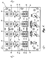
- FIGURE 1 illustrates the face of a representative panel 10 in accordance with the present invention, which is identical in appearance and, to the crew member, operation as a preexisting panel of conventional construction. Nevertheless, the construction of the improved panel 10 is vastly different, lighter, less bulky, and requires none of the routine maintenance required for the panel which it replaces.
- FIGURE 1 The panel of FIGURE 1 was selected for illustration and prototyping because of the variety of types of switches and indicating systems used.
- a toggle switch 12 with an operating lever 13 that swings in one plane (up and down) between "On” (closed) and "Off” (open) positions, is adjacent to a bottom row of rotary rheostats 14 and 14 ' .
- the rheostats 14 at the ends of the row have single cylindrical operating knobs 16.
- the middle rheostat 14 ' has an outer annular knob 16 ' for controlling one function and an inner cylindrical knob 16 for controlling another function.
- a row of push button switches 18 Immediately above the toggle switch 12 and rheostats 14 and 14 ' is a row of push button switches 18.
- Switches 18 are of a type having shuttered indicator light sections 20 and independently lit lower sections 22. Proceeding upward, there is a row of rotary switches 24 having multiple detent positions for their operating knobs 25. At the top of the panel 10 are two rows of annunciators 26 with internal lights.
- the panel of FIGURE 1 corresponds to a composite of two of many panel modules of a Boeing 747 aircraft. In the prior art design, switches of different manufacturers are selected and mounted in a mounting panel and hardwired to appropriate control circuitry, the wires being connected into bundles for standardized system connectors at the rear.
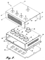
- FIGURE 2 shows some of the components of the systems control panel 10 in accordance with the present invention in partially exploded relationship.
- a standard light plate 30 is mounted on a machined front plate 32.
- plate 32 has bosses and standoffs for supporting a first or front printed wiring board or assembly (PWA) 34.
- PWA 34 has LEDs for the annunciators and Hall effect sensors for magnets carried by movable switch components.
- Side rails 36 space the front PWA 34 from a second or rear PWA 38.
- PWAs 34 and 38 have their circuits connected by standardized press-in, compliant pin connectors, but other technologies could be used for interconnecting the circuits of two PWAs.
- the rear PWA 38 is designed for connection of standard system connectors 40 of the type currently used, such as compliant pin connectors, which are coupled to the circuitry of the front and rear PWAs.
- standard system connectors 40 of the type currently used, such as compliant pin connectors, which are coupled to the circuitry of the front and rear PWAs.
- the top, bottom, and back of the assembly are closed by a rear cover 42. All that projects from the rear of the improved panel 10 are the standard system connectors 40 which mate with complemental connectors of the aircraft control systems.
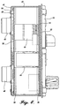
- FIGURE 3 the standard press-in connectors 44 can be seen, and the side rails 36 extending between corresponding side margins of the front and rear PWAs 34 and 38. Also seen are the comparative distances between the front machined panel 32, front PWA 34, and rear PWA 38.
- the connectors 44 also are seen in FIGURE 4, as well as the opposite sides 43 of the rear cover 42 which are in thermal contact with the front and rear PWAs and, through the mounting screws and studs 39, the side rails 36.
- FIGURES 3 and 4 some of the internal switch components that are described in detail below are shown diagrammatically in broken lines and some are removed. The positions of the rear connectors 40 and interwiring board connectors 44 are also seen in FIGURE 5.
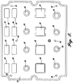
- the front light plate 30 is shown in FIGURES 6-8. Holes 48 are provided for parts of the various switches and annunciators, as well as mounting screws.
- the light plate is identical to that previously used, including an electrical connection 49 on its rear face seen in FIGURE 8, and therefore is not described in detail herein. In general, the face of the light plate is opaque, with the lettering being transparent or translucent so that the lettering is visible to the flight crew. The light plate fastens directly to the front of the machined front plate.
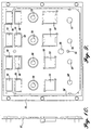
- the machined front plate 32 shown in FIGURE 9 (rear face) and FIGURE 10 (side elevation) preferably is formed of a nonmagnetic, heat conductive material such as aluminum, and has openings 50 corresponding generally to the shape and locations of the light plate openings 48. Opening 56 is aligned with and provides access to the light plate power connector 49 (FIGURE 8). In some instances, ribs or shoulders 52 are provided to act as keys for positive positioning of the components that pass through the openings. In addition, one or more short standoffs or raised rims 58 are provided to achieve the desired uniform spacing between the front plate 32 and front PWA 34 attached to the front plate, including a peripheral rim 58'. In the preferred embodiment, the spacing between the front plate and the adjacent face of the front PWA is uniformly 0.125 inch regardless of the type or combination of switches or annunciators used in the panel. This greatly simplifies the design of the panel.
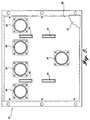
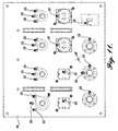
- FIGURE 11 does not show the circuit traces, but does show the location of several Hall effect sensors 59 which cooperate with the switches used in the present invention as described below and the connector 49' that mates with the light plate power connector.
- the broken lines indicate components of the switches which are described in detail below.
- FIGURE 12 is an enlarged diagrammatic view of a corner portion of the improved panel 10 in the area where the front PWA 34 contacts the machined front plate 32 and siderails 36.
- the wiring board has internal ground and power planes 62 and 64, respectively.
- a thermal plane i.e., a thin sheet or film of heat conductive material, is provided just below each flat exterior surface of the wiring board 34.
- Copper flooded thermal vias 70 are provided to thermally couple a thermal plane 66 with the panel housing consisting of the front plate 32, side rails 36 and the rear cover, all of which are heat conductive, nonmagnetic material such as aluminum.
- surface copper (or other heat conductive material) is provided on the PWA in position to contact heat conductive portions of the housing.
- Heat conducting components of the panel such as LEDs 70, voltage regulator 72, resistor 74, and any other heat generating components mounted on the PWA 34 can be thermally coupled to the adjacent thermal plane and/or surface copper for dissipating heat through the panel housing.
- Thermal management for the heat generating components which are mounted on the PWAs present thermal design constraints not often found in other applications, including the following:
- a thermal management method was developed which maintains the LED temperatures at a low level, and maintains front plate and light plate temperatures at a low level.
- LEDs and front plate components are isolated from heat generated by linear regulators, resistors and other circuitry mounted on the rear surface of a PWA. This is achieved by thermal isolation of front and rear sides of the PWA.
- a key challenge is to remove a large amount of heat generated by all high power switches and heat generating components, both for the front PWA and the rear PWA.
- the front PWA 34 In a high power condition, 24 watts must be removed from the front PWA 34. This can represent a thermal density of about 0.5 Watts per square inch, implying a temperature rise of 63°C if nothing is done to improve dissipation. Of this, only 4 Watts is dissipated on the front side, which contains the LEDs, the remainder of the power being dissipated on the rear side. To maintain long LED life and optimal performance, it is preferable to keep the LED temperature as low as is reasonable. While LEDs must be mounted on the front side of front PWA, higher temperature, higher dissipation components are mounted to the rear side.
- Thermal isolation between the front and rear sides is achieved by providing the buried thermal planes of, for example, 2-ounce copper (.0028 inch thick), very closely adjacent to the external faces. Dielectric material of a thickness of about .005 inch is provided between each thermal plane and the adjacent front or rear surface containing the surface mount components, which assists in effectively spreading the heat through the PWA to the edges. Just beneath each thermal plane is another 2-ounce copper plane for electrical purposes (power and ground). The location of this plane further helps to spread the heat.
- the total thickness of the PWA is approximately .105 inch, with approximately .089 inch of a thermal isolating material such as glass epoxy between the electrical planes. This provides a significant amount of thermal isolation from one side of the board to the other.
- Heat removal from the PWA is enhanced by the use of numerous copper flooded thermal vias 70 that are used to move heat from the near side thermal plane to faying surface copper on the exposed surfaces of the board.
- faying surface copper is located around the edges of the PWA, both the near and far sides, and at any other points where the PWA contacts the machined front plate.
- the PWA 34 is squeezed between the machined front plate 32 and the side rails 36.
- the machined front plate removes heat from the front of the printed wiring board, most of which is spaced a uniform distance, such as .125 inch, from the rear of the front plate.
- the thick side panels and rear cover provide heat removal from the backside of the PWA, which contains the components generating the most heat.
- thermal management for the rear PWA can be accomplished by surface faying of highly heat conductive material such as copper in contact with housing components, mounting screws and the thermally conductive bases of the rear connectors 40.
- a switch lever 13 is pivoted to a hollow switch body 76 for swinging in a single plane about the axis of a pivot pin 78.
- the switch body 76 has an enlarged rear portion 80 for fitting against the rear face of the front plate 32.
- the body has external threads for a front mounting nut 82 which clamps the switch body in position.
- the front end of the body 76 is approximately flush with the front face of the light plate 30.
- the enlargement 80 has a large, flat rear portion or flange 82.
- the thickness of enlargement 80 and its rear flange 82 are no more than the desired spacing between the front plate 32 and the front PWA 34, i.e., 0.125 inch in the preferred embodiment. If the thickness of the enlargement is much less, separate standoffs are used to maintain the spacing.
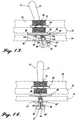
- a thin cam plate 86 is mounted on the rear flange 84, such as by short twist tabs 88 that extend through corresponding slots or notches in the rear flange 84. The cam plate fits in a central slot 91 (FIGURE 14) of the rear portion 90 of the operating lever 13 that extends rearward beyond the switch body 76.
- the rear end portion 90 of the operating lever 13 is bifurcated, with each bifurcation sliding along the cam plate 86 as the operating lever is swung about its pivot 78.
- a magnet carrier 94 is secured to the rear end of the switch operating lever, behind the rear edge of the cam plate 86.
- One or more small magnets 96 are mounted on the magnet carrier such that, as the operating lever is moved, the magnets move toward and away from one or more Hall effect sensors 59 mounted on the rear surface of the front PWA 34.
- the number and location of the Hall effect sensors will depend on the different operating positions for the lever 13. In the embodiment illustrated in FIGURE 14, it is desired to sense when the operating lever is in either of two positions, which can be accomplished by sensing whether magnets carried by the magnet carrier are in close proximity to a Hall effect sensor at one side or are located remote from the sensor.
- the detent positions are determined by the shape of the central cutout 98 of the cam plate 86.
- a cam follower in the form of a spring loaded ball 100 mounted in a blind bore of the rear end portion 90 of the operating lever rides along the contoured rear edge of the cutout 98.
- a first detent position is achieved with the operating lever swung in one direction, in which the ball 100 rests in a first depression of the cutout 98.
- the control circuitry need only detect whether the switch is in one position or the other, which is achieved by the output of the Hall effect sensor(s), indicating whether the magnet(s) 96 is/are close to or far from the sensor(s).
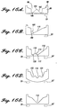
- FIGURE 16B The cam plate 86 of FIGURE 13 is shown removed from the rest of the components in FIGURE 16A.
- FIGURES 16B-16E Other configurations for the cam and its central cutout are shown in FIGURES 16B-16E.
- a single deep depression 108 is provided for biasing the operating lever to a position swung in one direction. From there the switch may be swung against the biasing force of the spring loaded ball as the ball moves along the ramp 110. However, when the switch lever is released, it will return to the position where the ball is received in the depression.
- a central depression 112 is provided for a central detent position.
- the lever can be moved against the biasing force of the spring loaded ball, with the ball moving along a short ramp 114 or long ramp 116. If moved along the short ramp 114, a short cusp 118 is reached, from which the lever is biased to a second, inclined detent position determined by a cam depression 120. Moving in the opposite direction, the switch lever can be moved away from the central position so that the ball moves up the long ramp 116 to the right, but when the switch lever is released, it will swing back to the central position.
- the switch may be moved in one direction to a detent position, which can be detected by Hall effect sensors 59 mounted at that side, or it may be moved in the opposite direction, to be detected by Hall effect sensors 59' mounted at the opposite side, but only the central position and one of the swung positions is a stable detent position.
- FIGURE 16D shows another configuration where the switch may be moved from a central detent position, defined by a cam depression 112, to either a rightward swung or leftward swung detent position, defined by depressions 122 and 124, and detected by Hall effect sensors 59, 59' appropriately mounted at those sides. All three positions, center, right, and left, are detent positions.
- the only detent position is the central position, determined by cam depression 112, but the switch may be moved in either direction from that position, to be detected by Hall effect sensors 59, 59' appropriately mounted on the front PWA, and the switch lever will return to the central position when released.
- magnet carriers for toggle switches can have magnets 96, 96'' at opposite sides of the central cam plate, as seen in FIGURE 14, for example, coacting with Hall effect sensors 59, 59'' at the appropriate sensing locations.
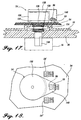
- FIGURES 17 and 18 show a rotary switch 24 that can be used in a solid state systems control panel in accordance with the present invention.
- the switch body 126 includes a threaded stem 128 extending through aligned holes 130 and 132 of the front PWA 34 and machined front plate 32.
- the rear portion of the body 126 is cylindrical, and of a diameter substantially greater than the stem 128 and the holes 130, 132 through which the stem extends.
- a front mounting nut 134 holds the switch body in position.
- An operating shaft 136 extends from inside the switch body and projects from the light plate 30 for attachment of the rotary operating knob 25. Rotation of the knob causes corresponding rotation of a rear magnet carrier 138.
- the magnet carrier includes a portion 140 extending forward, alongside the rear portion of the switch body 126, with a small magnet 96 at its forward end. Magnet 96 is positioned to pass close to one or more Hall effect sensors 59 mounted on the rear surface of the front PWA 34. By turning the operating knob 25, the rear magnet carrier 138, 140 is rotated to position the magnet 96 close to or remote from a Hall effect sensor 59.
- Angular positions of the switch knobs 25, shaft 136 and magnet carrier 138, 140 are differentiated by a rotary detent mechanism within the rear portion of the switch body 126.
- Such detent mechanism can be identical to internal detents used for existing mechanical rotary switches, such as rotary switches available from Cole Instrument Corporation of Santa Ana, California, for example.
- the number of active positions per switch position is determined by the number of magnets carried by the magnet carrier.
- FIGURE 18 illustrates a rotary switch mechanism having three active positions determined by proximity of the magnet 96 of the magnet carrier 138, 140 to three Hall effect sensors 59, 59' and 59'', mounted on the front PWA 34 in an arc traversed by magnet 96 as the actuating knob is turned.
- the invention may be easily extended to provide multiple poles, or multiple independent switches in one assembly by use of concentric shafts and magnet carriers.
- FIGURE 19 and FIGURE 20 show a conceptual design of a momentary-shorting switch, similar to the ignition-starting switch in an automobile.
- Shaft 136' is keyed to a first magnet carrier 138' that underlies a second magnet carrier 138'' which is not keyed to the shaft.
- the switch body 126' has a rearward projecting peg 142. Such peg is received in a long arcuate slot 143 of the forward (bottom) carrier 138' and a shorter slot 145 of the rearward (top) carrier 138''.
- the two carriers are biased for equal movement, such as by a spring 152.
- Carrier 138'' is of a larger radius than carrier 138', so that the magnet 96' carried by carrier 138'' is located farther from the axis of rotation than the magnet 96 carried by the inner carrier 138.
- Spring 152 engaged between the two carriers biases them to a position in which the magnets are approximately aligned radially, limited by a peg 144 projecting rearward from carrier 138' and engaging one end of an arcuate slot 148 of the rear carrier 138''.
- both magnet carriers swing together to a first "on” position in which the outer magnet 96' is in close proximity to Hall effect sensor 59' mounted on the front PWA 34.
- the stationary peg 142 engages the rear end 154 of slot 145 and prevents the top magnet carrier 138'' from additional rotation.
- the shaft 136' continues to rotate, only the other magnet carrier 138' will move with it, to a "start" position in which its magnet 96 is registered with the corresponding Hall effect sensor 59 on the PWA.
- an output signal is created in one sensor when the switch shaft is moved to a first on position, and an output signal is provided in the other sensor when the switch shaft is moved farther to another on position (referred to as the "start" position).
- a spring return is provided from the start position to the on position, and a mechanical detent within the switch body 126 retains the switch components in the on position until the switch is moved manually counterclockwise to the off position in which neither magnet is close enough to its associated sensor to activate the circuitry.
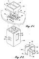
- FIGURES 21-23 illustrate a push button switch 18 that may be incorporated in a solid state flight deck module 10 in accordance with the present invention.
- the module includes the front light plate 30, machined front mounting plate 32 and front PWA 34. Standoffs 156 are provided to achieve the desired spacing between the machined front plate 32 and front PWA 34.
- the switch button 158 includes parallel, rearward extending legs 160 slidable in slots 162 of the front PWA 34.
- a switch body 163 is secured to the rear face of the PWA 34, such as by mounting screws 164.
- the two compartments 20 and 22 of the switch button are separated from each other by a center divider 166.
- LEDs 168 for the separate compartments are mounted on the front face of the PWA 34. Circuitry for actuating the LEDs resides in the PWA, preferably with heat producing components mounted on the rear face. In compartment 22, the LEDs are surrounded by a shroud 170 to prevent light from leaking into the adjacent compartment. Similarly, in compartment 20, the LEDs are enclosed within a telescoping housing assembly 172 which, when the button is depressed, opens a shutter assembly 174. The shutter assembly and its actuating mechanism are conventional and therefore are not further described herein. At the front side of the button, lenses 176 with desired indicia can be provided.
- the rear end portions 178 of the switch legs 160 carry an actuator cross bar 180.
- bar 180 has its opposite ends received in elongated slots 182 of fore and aft extending fingers 183 of a carrier 184 for an array of magnets 96.
- the switch button and bar 180 are moveable relative to the magnet carrier, as limited by the length of the slots 182.
- the carrier 184 also has two rearward extending latch fingers 183' each having a latching projection or lug 185 on its rear end portion. Lugs 185 cooperate with latch slots 182' and 182'' (FIGURE 21) of the switch body 163 to retain the carrier in alternate forward or rearward shifted positions.
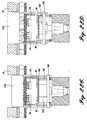
- a detent actuating rod 186 extends rearward from the cross bar 180 and cooperates with a conventional dual position detent mechanism 188, shown diagrammatically in FIGURES 22A-22D.
- a conventional dual position detent mechanism 188 shown diagrammatically in FIGURES 22A-22D.
- Various types of dual detents can be used and, therefore, the detent assembly is shown diagrammatically.
- unique to the present invention is the mechanism for controlling the travel of the magnet carrier 184 to position the magnets 96 either close to the PWA mounted Hall effect sensors 59 or at a position remote from the sensors.
- the detent mechanism 188 has an internal spring biasing the shaft 186 forward. In the "off" projected position shown in FIGURE 22A, shaft 186 is biased to move the cross bar 180 forward in the magnet carrier slots 182 and in corresponding slots 200 of the switch housing 163. In this position the latch lugs 185 engage in the forward latch slots 182'. If the button 158 is depressed to a position in which its front face is flush with the front face of the light plate 30, shown in FIGURE 22B, bar 180 is moved approximately to the rear ends of slots 182, and if the button is then released it will return to the projected position shown in FIGURE 22A without having moved the magnet carrier 184.
- the cross bar 180 seats in the rear ends of slots 182 and moves the magnet carrier rearward.
- a rear detent position is reached in which the latch lugs 185 engage in the rear latch slots 182'' such that the switch button and magnet carrier are retained in an inward or rearward shifted position, with the magnets sufficiently far from the PWA mounted sensors 59 for detecting actuation of the switch button, despite the button moving to the position of FIGURE 22D in which the front surface of the button 158 is approximately aligned with the front face of the light plate 30.
- the detent can be released and the switch button and magnet carrier returned to the position of FIGURE 22A by pressing the button inward to approximately the position of FIGURE 22C, followed by releasing the button for travel forward or outward, carrying with it the cross bar 180 and shifting the magnet carrier forward to position the magnets 96 closely adjacent to the Hall effect sensors 59.
- the push button switch described above uses an alternate action (i.e., push on, push off) detent mechanism.
- it may be configured as a non-latching mechanism to implement a momentary type switch.
- the magnet carrier can be positively keyed to the push button, or may be configured to move after the push button has been moved a predetermined distance, to be returned to the start position when the button is released.
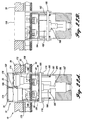
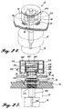
- a rheostat 14' can be implemented by mounting Hall effect sensors 50 on the rear surface of the PWA 34, with mechanism in the switch body 210 for moving permanent magnets 96 toward and away from the Hall effect sensors depending on the degree of rotation of operating knobs 16 and 16'.
- the rheostat body 210 includes a threaded stem 212 for a spacer nut 214 at the rear side of the mounting plate 32 and a front mounting nut 216 at the front side of the plate. This assembly maintains the rheostat body 210 in a fixed position relative to the machined front plate 32 and front PWA 34.
- the spacing between plate 32 and PWA 34 is the desired uniform distance, such as 0.125 inch.
- the rheostat body 210 includes one or more cylinders 218, each of which slidably receives a piston member 220.
- Each piston member has a permanent magnet 96 in line with a Hall effect sensor 59 mounted on the rear side of PWA 34.
- the outputs of the Hall effect sensors are functions of the distances between the magnets and the sensors, and therefore indicate the positions of the operating knobs.
- one of the operating knobs 16' is keyed to a shaft 222 extending through the light plate 30, and the stem 212 of the rheostat to a front cam disk 224 which rotates with shaft 222.
- the cam disk 224 has a helical cam slot 226.
- a transversely extending peg 228 from one of the pistons 220 rides in the helical cam slot 226.
- a second operating knob 16 is keyed to an inner shaft 230 which extends through a hollow central bore of shaft 222 to a rear cam disk 224' .
- Disk 224' has a helical cam slot 226' which receives the inner end portion of a transversely extending peg 228' of another of the pistons 220.
- FIGURE 25 shows two pistons at diametrically opposed locations, one controlled by knob 16 and the other by knob 16', in the preferred embodiment diametrically opposed pistons would be moved together by having pegs positioned in portions of the cam slot 226 at opposite sides of the cam disk 224. Similarly, the other two pistons would be located diametrically opposed from each other and controlled by rotation of knob 16' and the rear cam disk 224'. The pistons controlled by one knob would be located 90° from the pistons controlled by the other knob.
- FIGURE 26 shows a similar rheostat 14 having a single control knob 16 controlling a single shaft 230.
- Shaft 230 extends through the threaded stem 212 of the rheostat housing 210 which has cylinders 218 for slidable pistons 220.
- the housing 210 is mounted on the machined front plate 32 by a rear spacer nut 214 and front mounting nut 216.
- Shaft 230 controls rotation of a single cam disk 224 having a generally helical cam groove 226.
- Pistons 220 have one or more transversely extending pegs 228 with inner portions received in the groove 226.
- knob 16 rotation of the knob 16 causes a corresponding rotation of shaft 230 and cam disk 224, such that the pistons 220 are slid in the cylinders 218 to position permanent magnets 96 mounted at the front ends of the pistons closer to or farther from Hall effect sensors 59.
- annunciator assemblies 26 in the solid state flight deck module 10 in accordance with the present invention use LEDs 70 mounted on the front face of the front PWA 34.
- LEDs 70 mounted on the front face of the front PWA 34.
- a plurality of LEDs are used, three LEDs being used for each annunciator in the preferred embodiment.
- the LEDs project into specialized annunciator housings formed of multiple pieces.
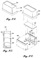
- the innermost parts of the housings are specialized reflectors 238 manufactured from or having their internal surfaces coated with a highly reflective material. Each reflector is formed by halves 240 which are mirror images of each other.
- Each half 240 has a base portion 242 with three generally semi-circular cutouts 244 such that, when the halves are brought together, three openings 246 are formed for the LEDs to project into the housing.
- a special lens 248 fits on the front or outer edges of the reflector halves 240.
- a unitary cap 250 is slid over the lens and reflector halves.
- the base of the cap 250 has a peripheral rim or lip 252 which, as seen in FIGURE 27, fits against a shoulder 52 of the machined front plate 32.
- the front PWA fits against the base of the cap 252, with the LEDs 70 projecting into the interior.
- the adjacent faces of the front PWA 34 and front machined plate are maintained at the desired uniform distance from each other so as to be compatible with the other components of the panel.
- the lens 248 and composite reflector 238 control the light emitted from the LEDs.
- the specific shape of the reflector is influenced by a combination of performance, cost, and overall ease of assembly. Light from each LED is emitted generally in all directions. Frustoconical sockets 254 around the openings for the LEDs assist in reflecting rearward directed light outward toward the annunciator lens.
- the walls 256 of the reflectors are specially shaped for achieving a high degree of readability of the legend incorporated in the annunciator lens. As best seen in FIGURE 30, such walls consist of a central portion 260 lying in a plane approximately perpendicular to the PWA.
- a shorter inner section 262 forms an angle of approximately +6° with the center portion, and a short outer portion 264 forms an angle of approximately X with the center portion.
- Maximum light transmission has been achieved by coating the entire interior of the reflector with a high efficiency aluminum reflective coating.
- the three sections of the annunciator walls approximate a parabola, and have a surprising effect on the readability of the lens legend, particularly at side angles up to 70°.
- the reflector shape gets larger as it gets closer to the exit surface. For example, such is the case with a parabolic headlight reflector where the light source is positioned at the focus, and the light is reflected at smaller and smaller angles off the surface as the light travels farther away from the light source. This results in a focused light output.
- a wide angle dispersed light output is achieved by making the reflecting surface smaller as the light travels toward the exit end of the reflector. This causes the light to leave the cavity at larger angles relative to the exiting surface.
- lens 248 also is a new design to achieve improved contrast as compared to known designs.
- lens 248 includes an upper layer 268 of neutral density attenuating material, such as Lexan of a thickness of about 0.015 inch thick.
- the outer surface of this layer is treated with a UV stable coating 270 such as the coating used for a keyboard overlay which produces both a hidden legend appearance when the display is not illuminated and provides chemical resistance to most common solvents.
- a legend layer 272 is provided consisting of a photographic emulsion in which the legend indicia is produced and then is bonded behind the neutral density filter, such bonds being represented as thin layers 274 in FIGURE 31.
- a clear sheet 280 of thin (0.020 inch) strength-reinforcing material such as 8010 Lexan is then bonded to the photographic emulsion film layer.
- the inside surface of the strength layer is also treated with UV stable hard coating 282.
- the coating on the surface which faces the reflectors allows more of the light which impinges on the lens at larger angles relative to normal to enter the lens rather than be reflected back toward the light source.
- the current preferred embodiment of the lens provides a transmission of 25-30% in the green and yellow spectrum while attenuating the light in the red and blue spectrum to less than 15%.
- the annunciator is used with LEDs producing light in the yellow-green spectrum.
- the annunciator assembly 26 is described above with reference to a single annunciator for a single hole through a machined front plate, such as any one of the holes 50 for the top two rows of the machined front plate shown in FIGURE 9, for example, corresponding to the annunciators 26 of FIGURE 1. Nevertheless, the design is adapted for flight deck panel modules consisting of banks of annunciators, such as the module 10' shown in FIGURE 32. Each annunciator has the features (internal reflectors, lens, and cap) described above. With reference to FIGURE 33, the machined front plate 34' can have long channels 284 with shoulders 286 for receiving rows of the annunciator assemblies 26, arranged side by side.
- the front PWA 34 retains the annunciator assemblies in position; compliant pin connectors 44 are provided for connecting the circuit of the front PWA 34 to the circuit of the rear PWA 38; and stand-offs 288 are provided for spacing the front and rear PWAs a desired distance apart. Mounting screws secure the rear cover 42' over the assembly such that the standard rear connectors 40 project rearward from the cover.
- Circuitry for the modules in accordance with the present invention is designed to be compatible with modules currently in use.
- One complication is noted above, namely, the desirability of providing magnets in different orientations so that some sensors detect positive magnetic fields while others detect negative magnetic fields when the magnets are in close proximity to the sensors.
- an appropriate solid state Hall effect sensor usable in the present invention is a model SS495 miniature ratiometric linear sensor, available from Honeywell. This sensor can be biased at 10 volts DC and have an output voltage signal that ranges linearly from 1 volt to 9 volts in response to magnetic field variations from -640 Gauss to +640 Gauss.
- a circuit appropriate for omnipolar sensing is shown in FIGURE 34.
- the Hall effect sensor U1 is biased to 10 volts DC (Vcc) by a circuit of the type described below with reference to FIGURE 37.
- the resistor divider formed by R3 and R4 establishes operate and release points for a comparator U2A for a positive magnetic field.
- Resistor divider R1 and R2 establishes operate and release points of comparator U2B for a negative magnetic field.
- the series resistor-diode networks R7, D1 and R8, D2 provide hysteresis for U2A and U2B, respectively, and both comparator open-collector outputs are wire ORed, with inverter buffer ICs U3A and U3B driving the output loads.
- Comparator operate and release thresholds have been set at sufficiently high levels that the circuit is immune to lightning induced transient magnetic fields. This eliminates the need for additional filtering, as could be required with other off-the-shelf digital Hall effect position sensors.
- Design thresholds for the Hall sensors are ⁇ 385 Gauss operate and ⁇ 250 Gauss release.
- the lightning induced transient field has been calculated to be a maximum of ⁇ 200 Gauss.
- Worst case field strength calculations show a maximum of 600 Gauss when any switch is in the on position (magnet close to a sensor). Therefore, an on device will not turn off in response to the lightning transient, and neither will sensor thresholds allow an off device to be turned on.
- Another consideration is the possibility of current in a wire bundle creating a magnetic field sufficient to operate a switch. Calculations have determined that wire bundles greater than 2.2 inches from a Hall sensor will not cause the sensor to change state, even during a lightning transient.
- Outputs from the circuit of FIGURE 34 are appropriate for any on-off condition, such as is desired for a toggle switch, rotary switch, or push button switch of the type described above.
- the output of the circuit of FIGURE 34 is used with a driver circuit. High side (28 volts) and low side (10 volts) driver circuits can be used, triggered by the output of the circuit of FIGURE 34, as represented by FIGURE 35.
- Rheostats require circuits providing a varying output depending on the position of a rotary knob.
- the preferred miniature ratiometric linear Hall effect sensor (Honeywell SS495) does provide a linear output.
- the linear output from the Honeywell sensor must be converted by a circuit to be proportional to knob rotation.
- a supply voltage 28 volts DC aircraft power - nominally 18 to 32 volts DC with higher and lower transients
- the regulator preferably also provides filtering and transient protection.
- An example application circuit is based on a National Semiconductor LM317.
- the regulated voltage is applied to the Hall effect sensor 59, such as 5 volts in a representative embodiment.
- the sensor output is proportional to the detected magnetic field.
- the sensor output is 0.5 times the regulated voltage or 2.5 volts in the representative circuit.
- Sensor output voltage will increase to a maximum of 4.5 volts in this example as ambient flux increases from 0.
- the sensor output voltage decreases to a minimum of 0.5 volts as ambient flux decreases from 0, i.e., goes negative.
- a buffer amplifier normalizes the Hall sensor voltage to a 0 to 5 volt range. This is accomplished by canceling the Hall effect zero flux offset, then amplifying the result by an appropriate gain.
- the analog position output will be effected.
- Other circuitry is added as required to control lamps, audio volume, heat controls, etc.
- the annunciator current regulator circuit provides a constant current drive to illuminate LED indicator devices.
- Previous technology utilizes incandescent lamps requiring approximately 80 milliamps per indicator. Lamp intensity varies considerably with fluctuations of the 28 volt DC bus voltage applied to the lamps.
- the new approach drives a fixed current through a string of LEDs that consume less than one quarter of the current required by incandescent lamps.
- the current level and thereby the intensity of the indicators are closely regulated using a two level regulator circuit, which can be of the general type shown in FIGURE 38.
- the indicator illumination level is solely determined by the voltage V s supplied to the indicators, represented by box 302. This input voltage is set by the flight crew by selecting a bright or dim illumination level (V b or V d ) through the master dim and test switch 300.
- the output current to the indicator is then selected to be at a bright or dim level via a comparator circuit 306 which determines whether the input voltage is above or below a threshold level, in this case 16 volts, which then regulates the current at the fixed dim or bright level.
- a threshold level in this case 16 volts
Landscapes
- Engineering & Computer Science (AREA)
- Microelectronics & Electronic Packaging (AREA)
- Switch Cases, Indication, And Locking (AREA)
- Pinball Game Machines (AREA)
- Fire-Extinguishing By Fire Departments, And Fire-Extinguishing Equipment And Control Thereof (AREA)
- Toys (AREA)
- Control Of Position, Course, Altitude, Or Attitude Of Moving Bodies (AREA)
Applications Claiming Priority (3)
| Application Number | Priority Date | Filing Date | Title |
|---|---|---|---|
| US23126899A | 1999-01-15 | 1999-01-15 | |
| US231268 | 1999-01-15 | ||
| CA002412106A CA2412106C (en) | 1999-01-15 | 2002-11-14 | Flight deck systems control panel |
Publications (3)
| Publication Number | Publication Date |
|---|---|
| EP1021074A2 true EP1021074A2 (de) | 2000-07-19 |
| EP1021074A3 EP1021074A3 (de) | 2001-03-28 |
| EP1021074B1 EP1021074B1 (de) | 2012-06-20 |
Family
ID=32963077
Family Applications (1)
| Application Number | Title | Priority Date | Filing Date |
|---|---|---|---|
| EP00200108A Expired - Lifetime EP1021074B1 (de) | 1999-01-15 | 2000-01-13 | Cockpit-Halbleiterplatten und deren Komponenten |
Country Status (3)
| Country | Link |
|---|---|
| US (1) | US6587056B1 (de) |
| EP (1) | EP1021074B1 (de) |
| CA (1) | CA2412106C (de) |
Cited By (4)
| Publication number | Priority date | Publication date | Assignee | Title |
|---|---|---|---|---|
| GB2429002A (en) * | 2005-08-08 | 2007-02-14 | Boeing Co | System and apparatus for flight deck module integration |
| WO2007047155A3 (en) * | 2005-10-14 | 2007-08-09 | Boeing Co | Systems and methods for lighting control in flight deck devices |
| CN102607587A (zh) * | 2004-03-31 | 2012-07-25 | 波音公司 | 控制航行器驾驶舱上信息的显示的方法和系统 |
| CN111137465A (zh) * | 2019-12-13 | 2020-05-12 | 中国航空工业集团公司西安飞机设计研究所 | 飞机音频设备外话控制调节装置和方法 |
Families Citing this family (15)
| Publication number | Priority date | Publication date | Assignee | Title |
|---|---|---|---|---|
| JP3920559B2 (ja) * | 2000-11-10 | 2007-05-30 | アルプス電気株式会社 | 手動入力装置 |
| US6885564B2 (en) * | 2003-02-11 | 2005-04-26 | Honeywell International Inc. | Electronics box having internal circuit cards interconnected to external connectors sans motherboard |
| FR2871986B1 (fr) * | 2004-06-16 | 2006-08-04 | Schneider Toshiba Inverter | Appareil de commande moteur |
| US20060243122A1 (en) * | 2005-05-02 | 2006-11-02 | James Carson | Musical instrument mounting adapter |
| US7552897B2 (en) * | 2005-07-14 | 2009-06-30 | The Boeing Company | Method and system for rotary code-based control |
| US7180437B1 (en) * | 2005-08-03 | 2007-02-20 | The Boeing Company | Parallel-to-serial converter |
| US7791506B2 (en) * | 2007-03-30 | 2010-09-07 | Zf Friedrichshafen Ag | Configurable networked user interface and switch pack |
| US8477504B2 (en) * | 2008-09-30 | 2013-07-02 | Raytheon Company | Systems and methods for blind-mate connector alignment |
| US8573992B2 (en) * | 2011-01-11 | 2013-11-05 | Little Engine Labs, Llc | Connector system and method |
| FR2974661B1 (fr) * | 2011-04-26 | 2014-02-28 | Eads Europ Aeronautic Defence | Dispositif de detection electronique modulaire |
| US8886372B2 (en) * | 2012-09-07 | 2014-11-11 | The Boeing Company | Flight deck touch-sensitive hardware controls |
| DE102013007927B4 (de) * | 2013-05-10 | 2014-12-24 | Hoerbiger Automatisierungstechnik Holding Gmbh | Antriebseinheit |
| WO2016157514A1 (ja) * | 2015-04-03 | 2016-10-06 | 三菱電機株式会社 | 制御盤および制御盤の更新方法 |
| FR3036842B1 (fr) * | 2015-05-27 | 2019-01-25 | Zodiac Aero Electric | Bouton de commande universel a effet hall pour interface homme-machine et interface homme-machine dotee de tel bouton de commande |
| JP7490530B2 (ja) * | 2020-10-22 | 2024-05-27 | 株式会社東芝 | 電子機器 |
Family Cites Families (23)
| Publication number | Priority date | Publication date | Assignee | Title |
|---|---|---|---|---|
| US3810167A (en) * | 1968-04-29 | 1974-05-07 | Vogue Instr Corp | Magnetic keyboard encoding device |
| JPS514049Y1 (de) * | 1970-07-23 | 1976-02-04 | ||
| US3851328A (en) * | 1973-01-17 | 1974-11-26 | Singer Co | Optical solid state switches |
| US4166200A (en) * | 1975-08-11 | 1979-08-28 | Tektronix, Inc. | Compact rotary switch construction |
| US4054860A (en) * | 1975-12-01 | 1977-10-18 | Oak Industries Inc. | Hall effect rotary switch |
| US4417200A (en) * | 1977-05-18 | 1983-11-22 | Herman Rosman | Current control |
| US4186342A (en) * | 1977-11-04 | 1980-01-29 | Texas Instruments Incorporated | Marine radio telephone |
| US4177499A (en) * | 1977-11-14 | 1979-12-04 | Volkmann Electric Drives Corporation | Electronic assembly with heat sink means |
| US4494109A (en) * | 1978-09-27 | 1985-01-15 | Bernin Victor M | Noncontacting keyboard employing a transformer element |
| AU542857B2 (en) | 1979-11-27 | 1985-03-21 | Foldcrown Limited | Engine analyser |
| US4366463A (en) * | 1981-05-22 | 1982-12-28 | Cooper Industries, Inc. | Keyboard |
| US4529967A (en) * | 1982-07-15 | 1985-07-16 | Gifft Thomas H | Non contacting inductive keyboard |
| US4489303A (en) * | 1983-06-03 | 1984-12-18 | Advanced Control Systems | Contactless switch and joystick controller using Hall elements |
| US4679033A (en) * | 1986-03-18 | 1987-07-07 | Hwang Shih Ming | Structure of vibration sensor |
| US5255155A (en) * | 1990-09-19 | 1993-10-19 | Sumitomo Wiring Systems, Ltd. | Structure of electric circuit panel for instrument panel of automobile and method for forming the same |
| US5173839A (en) * | 1990-12-10 | 1992-12-22 | Grumman Aerospace Corporation | Heat-dissipating method and device for led display |
| DE69407013T2 (de) * | 1993-09-17 | 1998-03-26 | Ford Motor Co | Bedienfeldbeleuchtung |
| US5535095A (en) * | 1994-04-15 | 1996-07-09 | Slater; R. Winston | Adjustable chassis for electronic apparatus for installation in variable thickness panels |
| DE19516547A1 (de) * | 1995-05-05 | 1996-11-14 | Bosch Gmbh Robert | Leiterplatte mit elektrisch leitender Schicht und Verfahren zur Herstellung einer Leiterplatte |
| US6154201A (en) * | 1996-11-26 | 2000-11-28 | Immersion Corporation | Control knob with multiple degrees of freedom and force feedback |
| US5861796A (en) * | 1997-04-18 | 1999-01-19 | Easton Corporation | Multiple position hall effect switch with lever actuator biasing mechanism |
| EP0879606A1 (de) | 1997-04-25 | 1998-11-25 | Paul Scherrer Institut | Verfahren zur Herstellung von facial Metall Tricarbonyl Verbindungen und ihre Anwendung zur Markierung von Biosubstraten |
| GB2332395A (en) * | 1997-12-19 | 1999-06-23 | Penny & Giles Computer Product | Magnetic keyboard with sealed Hall effect sensor |
-
2000
- 2000-01-13 EP EP00200108A patent/EP1021074B1/de not_active Expired - Lifetime
- 2000-03-31 US US09/540,103 patent/US6587056B1/en not_active Expired - Lifetime
-
2002
- 2002-11-14 CA CA002412106A patent/CA2412106C/en not_active Expired - Fee Related
Non-Patent Citations (1)
| Title |
|---|
| None |
Cited By (9)
| Publication number | Priority date | Publication date | Assignee | Title |
|---|---|---|---|---|
| CN102607587A (zh) * | 2004-03-31 | 2012-07-25 | 波音公司 | 控制航行器驾驶舱上信息的显示的方法和系统 |
| CN102607587B (zh) * | 2004-03-31 | 2014-12-17 | 波音公司 | 控制航行器驾驶舱上信息的显示的方法和系统 |
| GB2429002A (en) * | 2005-08-08 | 2007-02-14 | Boeing Co | System and apparatus for flight deck module integration |
| US7327283B2 (en) | 2005-08-08 | 2008-02-05 | The Boeing Company | System and apparatus for flight deck module integration |
| GB2429002B (en) * | 2005-08-08 | 2008-12-17 | Boeing Co | System And Apparatus For Flight Deck Module Integration |
| WO2007047155A3 (en) * | 2005-10-14 | 2007-08-09 | Boeing Co | Systems and methods for lighting control in flight deck devices |
| US7541697B2 (en) | 2005-10-14 | 2009-06-02 | The Boeing Company | Systems and methods for lighting control in flight deck devices |
| CN111137465A (zh) * | 2019-12-13 | 2020-05-12 | 中国航空工业集团公司西安飞机设计研究所 | 飞机音频设备外话控制调节装置和方法 |
| CN111137465B (zh) * | 2019-12-13 | 2021-10-15 | 中国航空工业集团公司西安飞机设计研究所 | 飞机音频设备外话控制调节装置和方法 |
Also Published As
| Publication number | Publication date |
|---|---|
| EP1021074B1 (de) | 2012-06-20 |
| US6587056B1 (en) | 2003-07-01 |
| CA2412106C (en) | 2007-03-27 |
| CA2412106A1 (en) | 2004-05-14 |
| EP1021074A3 (de) | 2001-03-28 |
Similar Documents
| Publication | Publication Date | Title |
|---|---|---|
| EP1021074B1 (de) | Cockpit-Halbleiterplatten und deren Komponenten | |
| CN101354974B (zh) | 开关设备 | |
| US7738229B2 (en) | Microprocessor-controlled multifunctioning light with intrinsically safe energy limiting | |
| US4056701A (en) | Low profile lighted push button switch | |
| TWI448641B (zh) | 具有可選擇輸出級數切換功能的照明裝置 | |
| US4262182A (en) | Fully illuminated backlit membrane touch switch | |
| US6310308B1 (en) | Compact push-button switch assembly | |
| US6089893A (en) | Illuminated electrical receptacle employing electroluminescent lamp member | |
| US6924744B2 (en) | Light emitting diode indicator | |
| US20070159008A1 (en) | Circuit for illuminating multiple light emitting devices | |
| US8973519B2 (en) | Recloser position indicator | |
| EP3572334B1 (de) | Multimodale flugzeugnavigationsleuchte und flugzeug damit | |
| US4554544A (en) | Diffuse incandescent runway marker light apparatus for overt/covert operation | |
| US2824954A (en) | Instrument panel lighting | |
| EP3914877A2 (de) | Multidirektionales schusswaffenlicht | |
| EP2063169B2 (de) | Beleuchtungsmittel | |
| CA2294700C (en) | Solid state flight deck modules and components thereof | |
| US2948073A (en) | Illuminated instrument panel | |
| GB2066575A (en) | Illuminated keyboard | |
| US2831282A (en) | Duo-panel with auxiliary printed circuit panel | |
| US3571585A (en) | Panel and edge lighting assembly | |
| US4851624A (en) | Control assembly having panel illumination means | |
| EP2724434B1 (de) | Schutzschalter modul mit beleuchteter frontplattenanzeige | |
| US6087601A (en) | Modular multi-purpose switch | |
| CN207800419U (zh) | 一种带显示标识的自锁保护盖 |
Legal Events
| Date | Code | Title | Description |
|---|---|---|---|
| PUAI | Public reference made under article 153(3) epc to a published international application that has entered the european phase |
Free format text: ORIGINAL CODE: 0009012 |
|
| AK | Designated contracting states |
Kind code of ref document: A2 Designated state(s): DE FR GB |
|
| AX | Request for extension of the european patent |
Free format text: AL;LT;LV;MK;RO;SI |
|
| PUAL | Search report despatched |
Free format text: ORIGINAL CODE: 0009013 |
|
| AK | Designated contracting states |
Kind code of ref document: A3 Designated state(s): AT BE CH CY DE DK ES FI FR GB GR IE IT LI LU MC NL PT SE |
|
| AX | Request for extension of the european patent |
Free format text: AL;LT;LV;MK;RO;SI |
|
| RIC1 | Information provided on ipc code assigned before grant |
Free format text: 7H 05K 5/00 A, 7H 03K 17/97 B, 7B 64D 43/00 B |
|
| 17P | Request for examination filed |
Effective date: 20010928 |
|
| AKX | Designation fees paid |
Free format text: AT BE CH LI |
|
| RBV | Designated contracting states (corrected) |
Designated state(s): DE FR GB |
|
| REG | Reference to a national code |
Ref country code: DE Ref legal event code: 8566 |
|
| 17Q | First examination report despatched |
Effective date: 20070903 |
|
| GRAP | Despatch of communication of intention to grant a patent |
Free format text: ORIGINAL CODE: EPIDOSNIGR1 |
|
| RAP1 | Party data changed (applicant data changed or rights of an application transferred) |
Owner name: THE BOEING COMPANY |
|
| RAP1 | Party data changed (applicant data changed or rights of an application transferred) |
Owner name: THE BOEING COMPANY |
|
| GRAS | Grant fee paid |
Free format text: ORIGINAL CODE: EPIDOSNIGR3 |
|
| GRAA | (expected) grant |
Free format text: ORIGINAL CODE: 0009210 |
|
| AK | Designated contracting states |
Kind code of ref document: B1 Designated state(s): DE FR GB |
|
| REG | Reference to a national code |
Ref country code: GB Ref legal event code: FG4D |
|
| REG | Reference to a national code |
Ref country code: DE Ref legal event code: R096 Ref document number: 60047286 Country of ref document: DE Effective date: 20120823 |
|
| PLBE | No opposition filed within time limit |
Free format text: ORIGINAL CODE: 0009261 |
|
| STAA | Information on the status of an ep patent application or granted ep patent |
Free format text: STATUS: NO OPPOSITION FILED WITHIN TIME LIMIT |
|
| 26N | No opposition filed |
Effective date: 20130321 |
|
| REG | Reference to a national code |
Ref country code: DE Ref legal event code: R097 Ref document number: 60047286 Country of ref document: DE Effective date: 20130321 |
|
| REG | Reference to a national code |
Ref country code: FR Ref legal event code: PLFP Year of fee payment: 17 |
|
| REG | Reference to a national code |
Ref country code: FR Ref legal event code: PLFP Year of fee payment: 18 |
|
| PGFP | Annual fee paid to national office [announced via postgrant information from national office to epo] |
Ref country code: DE Payment date: 20170125 Year of fee payment: 18 Ref country code: FR Payment date: 20170125 Year of fee payment: 18 |
|
| PGFP | Annual fee paid to national office [announced via postgrant information from national office to epo] |
Ref country code: GB Payment date: 20170127 Year of fee payment: 18 |
|
| REG | Reference to a national code |
Ref country code: DE Ref legal event code: R119 Ref document number: 60047286 Country of ref document: DE |
|
| GBPC | Gb: european patent ceased through non-payment of renewal fee |
Effective date: 20180113 |
|
| PG25 | Lapsed in a contracting state [announced via postgrant information from national office to epo] |
Ref country code: DE Free format text: LAPSE BECAUSE OF NON-PAYMENT OF DUE FEES Effective date: 20180801 Ref country code: FR Free format text: LAPSE BECAUSE OF NON-PAYMENT OF DUE FEES Effective date: 20180131 |
|
| REG | Reference to a national code |
Ref country code: FR Ref legal event code: ST Effective date: 20180928 |
|
| PG25 | Lapsed in a contracting state [announced via postgrant information from national office to epo] |
Ref country code: GB Free format text: LAPSE BECAUSE OF NON-PAYMENT OF DUE FEES Effective date: 20180113 |