EP1020891A2 - Low-transmission transparent layered structure - Google Patents
Low-transmission transparent layered structure Download PDFInfo
- Publication number
- EP1020891A2 EP1020891A2 EP00300328A EP00300328A EP1020891A2 EP 1020891 A2 EP1020891 A2 EP 1020891A2 EP 00300328 A EP00300328 A EP 00300328A EP 00300328 A EP00300328 A EP 00300328A EP 1020891 A2 EP1020891 A2 EP 1020891A2
- Authority
- EP
- European Patent Office
- Prior art keywords
- low
- fine particles
- transmission
- layered structure
- transmission transparent
- Prior art date
- Legal status (The legal status is an assumption and is not a legal conclusion. Google has not performed a legal analysis and makes no representation as to the accuracy of the status listed.)
- Granted
Links
- 239000010419 fine particle Substances 0.000 claims abstract description 285
- 239000000758 substrate Substances 0.000 claims abstract description 111
- 230000005540 biological transmission Effects 0.000 claims abstract description 110
- XEEYBQQBJWHFJM-UHFFFAOYSA-N Iron Chemical compound [Fe] XEEYBQQBJWHFJM-UHFFFAOYSA-N 0.000 claims abstract description 104
- OKTJSMMVPCPJKN-UHFFFAOYSA-N Carbon Chemical compound [C] OKTJSMMVPCPJKN-UHFFFAOYSA-N 0.000 claims abstract description 68
- 229910052799 carbon Inorganic materials 0.000 claims abstract description 68
- 239000011230 binding agent Substances 0.000 claims abstract description 67
- 229910052742 iron Inorganic materials 0.000 claims abstract description 53
- 239000000049 pigment Substances 0.000 claims abstract description 53
- 239000002131 composite material Substances 0.000 claims abstract description 52
- 229910052802 copper Inorganic materials 0.000 claims abstract description 52
- 239000010949 copper Substances 0.000 claims abstract description 52
- RYGMFSIKBFXOCR-UHFFFAOYSA-N Copper Chemical compound [Cu] RYGMFSIKBFXOCR-UHFFFAOYSA-N 0.000 claims abstract description 51
- WPBNNNQJVZRUHP-UHFFFAOYSA-L manganese(2+);methyl n-[[2-(methoxycarbonylcarbamothioylamino)phenyl]carbamothioyl]carbamate;n-[2-(sulfidocarbothioylamino)ethyl]carbamodithioate Chemical compound [Mn+2].[S-]C(=S)NCCNC([S-])=S.COC(=O)NC(=S)NC1=CC=CC=C1NC(=S)NC(=O)OC WPBNNNQJVZRUHP-UHFFFAOYSA-L 0.000 claims abstract description 51
- 239000002245 particle Substances 0.000 claims abstract description 50
- 150000003609 titanium compounds Chemical class 0.000 claims abstract description 43
- 239000000470 constituent Substances 0.000 claims abstract description 42
- 239000011159 matrix material Substances 0.000 claims abstract description 38
- 239000007788 liquid Substances 0.000 claims description 121
- 239000011248 coating agent Substances 0.000 claims description 85
- 238000000576 coating method Methods 0.000 claims description 85
- 238000000034 method Methods 0.000 claims description 57
- VYPSYNLAJGMNEJ-UHFFFAOYSA-N Silicium dioxide Chemical compound O=[Si]=O VYPSYNLAJGMNEJ-UHFFFAOYSA-N 0.000 claims description 54
- 229910052814 silicon oxide Inorganic materials 0.000 claims description 27
- 239000010936 titanium Substances 0.000 claims description 25
- 229910052719 titanium Inorganic materials 0.000 claims description 24
- RTAQQCXQSZGOHL-UHFFFAOYSA-N Titanium Chemical compound [Ti] RTAQQCXQSZGOHL-UHFFFAOYSA-N 0.000 claims description 23
- RMAQACBXLXPBSY-UHFFFAOYSA-N silicic acid Chemical compound O[Si](O)(O)O RMAQACBXLXPBSY-UHFFFAOYSA-N 0.000 claims description 23
- 239000002904 solvent Substances 0.000 claims description 16
- GWEVSGVZZGPLCZ-UHFFFAOYSA-N Titan oxide Chemical compound O=[Ti]=O GWEVSGVZZGPLCZ-UHFFFAOYSA-N 0.000 claims description 14
- 238000002156 mixing Methods 0.000 claims description 14
- 238000013329 compounding Methods 0.000 claims description 10
- OGIDPMRJRNCKJF-UHFFFAOYSA-N titanium oxide Inorganic materials [Ti]=O OGIDPMRJRNCKJF-UHFFFAOYSA-N 0.000 claims description 8
- AMGQUBHHOARCQH-UHFFFAOYSA-N indium;oxotin Chemical compound [In].[Sn]=O AMGQUBHHOARCQH-UHFFFAOYSA-N 0.000 claims description 6
- XXLJGBGJDROPKW-UHFFFAOYSA-N antimony;oxotin Chemical compound [Sb].[Sn]=O XXLJGBGJDROPKW-UHFFFAOYSA-N 0.000 claims description 5
- 230000005684 electric field Effects 0.000 abstract description 8
- 239000010410 layer Substances 0.000 description 237
- 239000010408 film Substances 0.000 description 117
- KFZMGEQAYNKOFK-UHFFFAOYSA-N Isopropanol Chemical compound CC(C)O KFZMGEQAYNKOFK-UHFFFAOYSA-N 0.000 description 78
- LFQSCWFLJHTTHZ-UHFFFAOYSA-N Ethanol Chemical compound CCO LFQSCWFLJHTTHZ-UHFFFAOYSA-N 0.000 description 61
- 239000011521 glass Substances 0.000 description 59
- 230000000052 comparative effect Effects 0.000 description 48
- QTBSBXVTEAMEQO-UHFFFAOYSA-N Acetic acid Chemical compound CC(O)=O QTBSBXVTEAMEQO-UHFFFAOYSA-N 0.000 description 27
- ARXJGSRGQADJSQ-UHFFFAOYSA-N 1-methoxypropan-2-ol Chemical compound COCC(C)O ARXJGSRGQADJSQ-UHFFFAOYSA-N 0.000 description 25
- XLYOFNOQVPJJNP-UHFFFAOYSA-N water Substances O XLYOFNOQVPJJNP-UHFFFAOYSA-N 0.000 description 23
- 229910002480 Cu-O Inorganic materials 0.000 description 20
- BPQQTUXANYXVAA-UHFFFAOYSA-N Orthosilicate Chemical compound [O-][Si]([O-])([O-])[O-] BPQQTUXANYXVAA-UHFFFAOYSA-N 0.000 description 18
- 229910000410 antimony oxide Inorganic materials 0.000 description 17
- SWXVUIWOUIDPGS-UHFFFAOYSA-N diacetone alcohol Chemical compound CC(=O)CC(C)(C)O SWXVUIWOUIDPGS-UHFFFAOYSA-N 0.000 description 16
- MCMNRKCIXSYSNV-UHFFFAOYSA-N Zirconium dioxide Chemical compound O=[Zr]=O MCMNRKCIXSYSNV-UHFFFAOYSA-N 0.000 description 14
- 239000007864 aqueous solution Substances 0.000 description 14
- 239000000203 mixture Substances 0.000 description 14
- 229910052681 coesite Inorganic materials 0.000 description 13
- 229910052906 cristobalite Inorganic materials 0.000 description 13
- 239000006185 dispersion Substances 0.000 description 13
- 239000000377 silicon dioxide Substances 0.000 description 13
- 229910052682 stishovite Inorganic materials 0.000 description 13
- 229910052905 tridymite Inorganic materials 0.000 description 13
- QGZKDVFQNNGYKY-UHFFFAOYSA-N Ammonia Chemical compound N QGZKDVFQNNGYKY-UHFFFAOYSA-N 0.000 description 11
- 239000000126 substance Substances 0.000 description 10
- 239000000243 solution Substances 0.000 description 9
- FAPWRFPIFSIZLT-UHFFFAOYSA-M Sodium chloride Chemical compound [Na+].[Cl-] FAPWRFPIFSIZLT-UHFFFAOYSA-M 0.000 description 8
- 239000002270 dispersing agent Substances 0.000 description 8
- 239000003973 paint Substances 0.000 description 8
- 239000011324 bead Substances 0.000 description 7
- 238000004519 manufacturing process Methods 0.000 description 7
- 238000006068 polycondensation reaction Methods 0.000 description 7
- LRHPLDYGYMQRHN-UHFFFAOYSA-N N-Butanol Chemical compound CCCCO LRHPLDYGYMQRHN-UHFFFAOYSA-N 0.000 description 6
- 238000010438 heat treatment Methods 0.000 description 6
- 238000004528 spin coating Methods 0.000 description 6
- 229910021529 ammonia Inorganic materials 0.000 description 5
- 239000004033 plastic Substances 0.000 description 5
- 230000015572 biosynthetic process Effects 0.000 description 4
- 238000001035 drying Methods 0.000 description 4
- 239000002356 single layer Substances 0.000 description 4
- 239000011780 sodium chloride Substances 0.000 description 4
- 206010052128 Glare Diseases 0.000 description 3
- -1 alkyl silicate Chemical compound 0.000 description 3
- 238000007786 electrostatic charging Methods 0.000 description 3
- 230000001976 improved effect Effects 0.000 description 3
- 238000002310 reflectometry Methods 0.000 description 3
- 239000007787 solid Substances 0.000 description 3
- IJGRMHOSHXDMSA-UHFFFAOYSA-N Atomic nitrogen Chemical compound N#N IJGRMHOSHXDMSA-UHFFFAOYSA-N 0.000 description 2
- UQSXHKLRYXJYBZ-UHFFFAOYSA-N Iron oxide Chemical compound [Fe]=O UQSXHKLRYXJYBZ-UHFFFAOYSA-N 0.000 description 2
- GRYLNZFGIOXLOG-UHFFFAOYSA-N Nitric acid Chemical compound O[N+]([O-])=O GRYLNZFGIOXLOG-UHFFFAOYSA-N 0.000 description 2
- QCWXUUIWCKQGHC-UHFFFAOYSA-N Zirconium Chemical compound [Zr] QCWXUUIWCKQGHC-UHFFFAOYSA-N 0.000 description 2
- PNEYBMLMFCGWSK-UHFFFAOYSA-N aluminium oxide Inorganic materials [O-2].[O-2].[O-2].[Al+3].[Al+3] PNEYBMLMFCGWSK-UHFFFAOYSA-N 0.000 description 2
- 239000012298 atmosphere Substances 0.000 description 2
- 238000010276 construction Methods 0.000 description 2
- 238000007606 doctor blade method Methods 0.000 description 2
- 230000007062 hydrolysis Effects 0.000 description 2
- 238000006460 hydrolysis reaction Methods 0.000 description 2
- 230000003301 hydrolyzing effect Effects 0.000 description 2
- JEIPFZHSYJVQDO-UHFFFAOYSA-N iron(III) oxide Inorganic materials O=[Fe]O[Fe]=O JEIPFZHSYJVQDO-UHFFFAOYSA-N 0.000 description 2
- ORUIBWPALBXDOA-UHFFFAOYSA-L magnesium fluoride Chemical compound [F-].[F-].[Mg+2] ORUIBWPALBXDOA-UHFFFAOYSA-L 0.000 description 2
- 229910001635 magnesium fluoride Inorganic materials 0.000 description 2
- 229910052748 manganese Inorganic materials 0.000 description 2
- 239000011572 manganese Substances 0.000 description 2
- 229910017604 nitric acid Inorganic materials 0.000 description 2
- 229920000642 polymer Polymers 0.000 description 2
- 239000005361 soda-lime glass Substances 0.000 description 2
- 238000005507 spraying Methods 0.000 description 2
- LFQCEHFDDXELDD-UHFFFAOYSA-N tetramethyl orthosilicate Chemical compound CO[Si](OC)(OC)OC LFQCEHFDDXELDD-UHFFFAOYSA-N 0.000 description 2
- 229910052726 zirconium Inorganic materials 0.000 description 2
- UFHFLCQGNIYNRP-UHFFFAOYSA-N Hydrogen Chemical compound [H][H] UFHFLCQGNIYNRP-UHFFFAOYSA-N 0.000 description 1
- 229910003081 TiO2−x Inorganic materials 0.000 description 1
- 239000002253 acid Substances 0.000 description 1
- 239000003377 acid catalyst Substances 0.000 description 1
- 239000003513 alkali Substances 0.000 description 1
- GVFOJDIFWSDNOY-UHFFFAOYSA-N antimony tin Chemical compound [Sn].[Sb] GVFOJDIFWSDNOY-UHFFFAOYSA-N 0.000 description 1
- 230000008033 biological extinction Effects 0.000 description 1
- 239000006229 carbon black Substances 0.000 description 1
- 239000008199 coating composition Substances 0.000 description 1
- 150000001875 compounds Chemical class 0.000 description 1
- 230000001066 destructive effect Effects 0.000 description 1
- 230000006866 deterioration Effects 0.000 description 1
- 238000007865 diluting Methods 0.000 description 1
- 239000000428 dust Substances 0.000 description 1
- 230000000694 effects Effects 0.000 description 1
- 239000001257 hydrogen Substances 0.000 description 1
- 229910052739 hydrogen Inorganic materials 0.000 description 1
- 238000007654 immersion Methods 0.000 description 1
- MRNHPUHPBOKKQT-UHFFFAOYSA-N indium;tin;hydrate Chemical compound O.[In].[Sn] MRNHPUHPBOKKQT-UHFFFAOYSA-N 0.000 description 1
- 239000000463 material Substances 0.000 description 1
- 229910052751 metal Inorganic materials 0.000 description 1
- 239000002184 metal Substances 0.000 description 1
- 229910052757 nitrogen Inorganic materials 0.000 description 1
- 230000003287 optical effect Effects 0.000 description 1
- 239000012788 optical film Substances 0.000 description 1
- 239000012466 permeate Substances 0.000 description 1
- 230000002265 prevention Effects 0.000 description 1
- 230000001681 protective effect Effects 0.000 description 1
- 239000004576 sand Substances 0.000 description 1
- 229910052596 spinel Inorganic materials 0.000 description 1
- 239000011029 spinel Substances 0.000 description 1
- LLZRNZOLAXHGLL-UHFFFAOYSA-J titanic acid Chemical compound O[Ti](O)(O)O LLZRNZOLAXHGLL-UHFFFAOYSA-J 0.000 description 1
- XJDNKRIXUMDJCW-UHFFFAOYSA-J titanium tetrachloride Chemical compound Cl[Ti](Cl)(Cl)Cl XJDNKRIXUMDJCW-UHFFFAOYSA-J 0.000 description 1
- 230000000007 visual effect Effects 0.000 description 1
Images




Classifications
-
- H—ELECTRICITY
- H01—ELECTRIC ELEMENTS
- H01J—ELECTRIC DISCHARGE TUBES OR DISCHARGE LAMPS
- H01J29/00—Details of cathode-ray tubes or of electron-beam tubes of the types covered by group H01J31/00
- H01J29/86—Vessels; Containers; Vacuum locks
- H01J29/89—Optical or photographic arrangements structurally combined or co-operating with the vessel
- H01J29/896—Anti-reflection means, e.g. eliminating glare due to ambient light
-
- C—CHEMISTRY; METALLURGY
- C03—GLASS; MINERAL OR SLAG WOOL
- C03C—CHEMICAL COMPOSITION OF GLASSES, GLAZES OR VITREOUS ENAMELS; SURFACE TREATMENT OF GLASS; SURFACE TREATMENT OF FIBRES OR FILAMENTS MADE FROM GLASS, MINERALS OR SLAGS; JOINING GLASS TO GLASS OR OTHER MATERIALS
- C03C17/00—Surface treatment of glass, not in the form of fibres or filaments, by coating
- C03C17/006—Surface treatment of glass, not in the form of fibres or filaments, by coating with materials of composite character
- C03C17/007—Surface treatment of glass, not in the form of fibres or filaments, by coating with materials of composite character containing a dispersed phase, e.g. particles, fibres or flakes, in a continuous phase
-
- C—CHEMISTRY; METALLURGY
- C03—GLASS; MINERAL OR SLAG WOOL
- C03C—CHEMICAL COMPOSITION OF GLASSES, GLAZES OR VITREOUS ENAMELS; SURFACE TREATMENT OF GLASS; SURFACE TREATMENT OF FIBRES OR FILAMENTS MADE FROM GLASS, MINERALS OR SLAGS; JOINING GLASS TO GLASS OR OTHER MATERIALS
- C03C17/00—Surface treatment of glass, not in the form of fibres or filaments, by coating
- C03C17/34—Surface treatment of glass, not in the form of fibres or filaments, by coating with at least two coatings having different compositions
-
- C—CHEMISTRY; METALLURGY
- C03—GLASS; MINERAL OR SLAG WOOL
- C03C—CHEMICAL COMPOSITION OF GLASSES, GLAZES OR VITREOUS ENAMELS; SURFACE TREATMENT OF GLASS; SURFACE TREATMENT OF FIBRES OR FILAMENTS MADE FROM GLASS, MINERALS OR SLAGS; JOINING GLASS TO GLASS OR OTHER MATERIALS
- C03C17/00—Surface treatment of glass, not in the form of fibres or filaments, by coating
- C03C17/34—Surface treatment of glass, not in the form of fibres or filaments, by coating with at least two coatings having different compositions
- C03C17/3411—Surface treatment of glass, not in the form of fibres or filaments, by coating with at least two coatings having different compositions with at least two coatings of inorganic materials
-
- H—ELECTRICITY
- H01—ELECTRIC ELEMENTS
- H01J—ELECTRIC DISCHARGE TUBES OR DISCHARGE LAMPS
- H01J29/00—Details of cathode-ray tubes or of electron-beam tubes of the types covered by group H01J31/00
- H01J29/86—Vessels; Containers; Vacuum locks
- H01J29/867—Means associated with the outside of the vessel for shielding, e.g. magnetic shields
- H01J29/868—Screens covering the input or output face of the vessel, e.g. transparent anti-static coatings, X-ray absorbing layers
-
- C—CHEMISTRY; METALLURGY
- C03—GLASS; MINERAL OR SLAG WOOL
- C03C—CHEMICAL COMPOSITION OF GLASSES, GLAZES OR VITREOUS ENAMELS; SURFACE TREATMENT OF GLASS; SURFACE TREATMENT OF FIBRES OR FILAMENTS MADE FROM GLASS, MINERALS OR SLAGS; JOINING GLASS TO GLASS OR OTHER MATERIALS
- C03C2217/00—Coatings on glass
- C03C2217/40—Coatings comprising at least one inhomogeneous layer
- C03C2217/43—Coatings comprising at least one inhomogeneous layer consisting of a dispersed phase in a continuous phase
- C03C2217/44—Coatings comprising at least one inhomogeneous layer consisting of a dispersed phase in a continuous phase characterized by the composition of the continuous phase
- C03C2217/45—Inorganic continuous phases
-
- C—CHEMISTRY; METALLURGY
- C03—GLASS; MINERAL OR SLAG WOOL
- C03C—CHEMICAL COMPOSITION OF GLASSES, GLAZES OR VITREOUS ENAMELS; SURFACE TREATMENT OF GLASS; SURFACE TREATMENT OF FIBRES OR FILAMENTS MADE FROM GLASS, MINERALS OR SLAGS; JOINING GLASS TO GLASS OR OTHER MATERIALS
- C03C2217/00—Coatings on glass
- C03C2217/40—Coatings comprising at least one inhomogeneous layer
- C03C2217/43—Coatings comprising at least one inhomogeneous layer consisting of a dispersed phase in a continuous phase
- C03C2217/46—Coatings comprising at least one inhomogeneous layer consisting of a dispersed phase in a continuous phase characterized by the dispersed phase
- C03C2217/47—Coatings comprising at least one inhomogeneous layer consisting of a dispersed phase in a continuous phase characterized by the dispersed phase consisting of a specific material
- C03C2217/475—Inorganic materials
-
- C—CHEMISTRY; METALLURGY
- C03—GLASS; MINERAL OR SLAG WOOL
- C03C—CHEMICAL COMPOSITION OF GLASSES, GLAZES OR VITREOUS ENAMELS; SURFACE TREATMENT OF GLASS; SURFACE TREATMENT OF FIBRES OR FILAMENTS MADE FROM GLASS, MINERALS OR SLAGS; JOINING GLASS TO GLASS OR OTHER MATERIALS
- C03C2217/00—Coatings on glass
- C03C2217/40—Coatings comprising at least one inhomogeneous layer
- C03C2217/43—Coatings comprising at least one inhomogeneous layer consisting of a dispersed phase in a continuous phase
- C03C2217/46—Coatings comprising at least one inhomogeneous layer consisting of a dispersed phase in a continuous phase characterized by the dispersed phase
- C03C2217/47—Coatings comprising at least one inhomogeneous layer consisting of a dispersed phase in a continuous phase characterized by the dispersed phase consisting of a specific material
- C03C2217/475—Inorganic materials
- C03C2217/476—Tin oxide or doped tin oxide
-
- C—CHEMISTRY; METALLURGY
- C03—GLASS; MINERAL OR SLAG WOOL
- C03C—CHEMICAL COMPOSITION OF GLASSES, GLAZES OR VITREOUS ENAMELS; SURFACE TREATMENT OF GLASS; SURFACE TREATMENT OF FIBRES OR FILAMENTS MADE FROM GLASS, MINERALS OR SLAGS; JOINING GLASS TO GLASS OR OTHER MATERIALS
- C03C2217/00—Coatings on glass
- C03C2217/40—Coatings comprising at least one inhomogeneous layer
- C03C2217/43—Coatings comprising at least one inhomogeneous layer consisting of a dispersed phase in a continuous phase
- C03C2217/46—Coatings comprising at least one inhomogeneous layer consisting of a dispersed phase in a continuous phase characterized by the dispersed phase
- C03C2217/48—Coatings comprising at least one inhomogeneous layer consisting of a dispersed phase in a continuous phase characterized by the dispersed phase having a specific function
- C03C2217/485—Pigments
-
- H—ELECTRICITY
- H01—ELECTRIC ELEMENTS
- H01J—ELECTRIC DISCHARGE TUBES OR DISCHARGE LAMPS
- H01J2229/00—Details of cathode ray tubes or electron beam tubes
- H01J2229/88—Coatings
- H01J2229/882—Coatings having particular electrical resistive or conductive properties
-
- H—ELECTRICITY
- H01—ELECTRIC ELEMENTS
- H01J—ELECTRIC DISCHARGE TUBES OR DISCHARGE LAMPS
- H01J2229/00—Details of cathode ray tubes or electron beam tubes
- H01J2229/89—Optical components associated with the vessel
- H01J2229/8913—Anti-reflection, anti-glare, viewing angle and contrast improving treatments or devices
-
- Y—GENERAL TAGGING OF NEW TECHNOLOGICAL DEVELOPMENTS; GENERAL TAGGING OF CROSS-SECTIONAL TECHNOLOGIES SPANNING OVER SEVERAL SECTIONS OF THE IPC; TECHNICAL SUBJECTS COVERED BY FORMER USPC CROSS-REFERENCE ART COLLECTIONS [XRACs] AND DIGESTS
- Y10—TECHNICAL SUBJECTS COVERED BY FORMER USPC
- Y10T—TECHNICAL SUBJECTS COVERED BY FORMER US CLASSIFICATION
- Y10T428/00—Stock material or miscellaneous articles
- Y10T428/25—Web or sheet containing structurally defined element or component and including a second component containing structurally defined particles
- Y10T428/256—Heavy metal or aluminum or compound thereof
-
- Y—GENERAL TAGGING OF NEW TECHNOLOGICAL DEVELOPMENTS; GENERAL TAGGING OF CROSS-SECTIONAL TECHNOLOGIES SPANNING OVER SEVERAL SECTIONS OF THE IPC; TECHNICAL SUBJECTS COVERED BY FORMER USPC CROSS-REFERENCE ART COLLECTIONS [XRACs] AND DIGESTS
- Y10—TECHNICAL SUBJECTS COVERED BY FORMER USPC
- Y10T—TECHNICAL SUBJECTS COVERED BY FORMER US CLASSIFICATION
- Y10T428/00—Stock material or miscellaneous articles
- Y10T428/25—Web or sheet containing structurally defined element or component and including a second component containing structurally defined particles
- Y10T428/256—Heavy metal or aluminum or compound thereof
- Y10T428/257—Iron oxide or aluminum oxide
Definitions
- the present invention relates to a low-transmission transparent layered structure comprising a transparent substrate and a low-transmission transparent layer formed thereon, or a transparent substrate and two layer films made of a low-transmission transparent layer and a transparent coat layer successively formed thereon, which is used as a front plate, etc., of a display device such as, for example, a cathode ray tube (CRT), etc.
- a display device such as, for example, a cathode ray tube (CRT), etc.
- the invention relates to a low-transmission transparent layered structure which has a flat transmission profile, can further impart a low reflectance and antistatic and electric field shielding functions, and can reduce the production cost thereof, and also a production method of the layered structure and also a display device to which the low-transmission transparent layered structure is applied.
- CTR cathode ray tube
- a method of using a face panel (the front face panel of CRT) having a low transmission and a method of applying a coating having a low transmission to a face panel having a relatively high transmission are considered but from the point that the transmission of CRT can be freely controlled, the latter method is advantageous.
- the anti-glare treatment may be practiced even by a method of forming fine roughness on the surface of the face panel to increase the diffused reflection at the surface, but because in the case of using this method, the resolution is lowered to deteriorate the image quality, the method cannot be said to be so preferred.
- a double layer structure film wherein the optical film thicknesses of the high refractive index film and the low refractive index film are established to 1/4 ⁇ and 1/4 ⁇ , 1/2 ⁇ and 1/4 ⁇ ( ⁇ : wavelength) is generally employed.
- the electromagnetic waves are generated from deflecting coils and flyback transformers and the leakage of magnetic fields can be prevented in its greater part by designing, e.g., by the changing of deflecting coils in shape.
- As for the leakage of electric fields it can be prevented by forming a transparent electrically conductive layer on the surface of the face panel of CRT.
- the surface resistance of the transparent electrically conductive layer is from about 10 8 to 10 10 ⁇ /square for the electrostatic charging prevention and is at most 10 6 ⁇ /square for electric field shielding.
- a method using tin antimony oxide (ATO) fine particles or indium tin oxide (ITO) fine particles as the transparent fine particles, and after coating a transparent conductive fine particle-containing coating liquid formed by dispersing the transparent conductive fine particles in a solvent together with a binder such as an alkyl silicate on the face panel of CRT followed by drying, heat-treating the coated layer at a temperature of about 200°C to form a transparent electrically conductive layer is known.
- the above-described transparent conductive fine particles used in the method do not absorb a visible light, to obtain a low-transmission film for improving the contrast, it is necessary to incorporate carbon fine particles, etc., in the transparent electrically conductive layer, and when carbon fine particles are incorporated, there is a problem that a flat transmission profile is not obtained and the film coated is colored in a brownish color as in the above-described case.
- the present invention has been made in view of the problems described above and an object of this invention is to provide a low-transmission transparent layered structure having particularly a flat transmission profile, capable of imparting a low reflectance and an antistatic/electric field shielding function, and capable of reducing the production cost and also to a production method of the low-transmission transparent layered structure, and further to provide a display device to which the low-transmission transparent layered structure is applied.
- the low-transmission transparent layered structure of the 1st embodiment of the invention for attaining the above-described objects is a low-transmission transparent layered structure comprising a transparent substrate and a low-transmission transparent layer formed on the transparent substrate, wherein the low-transmission transparent layer is constituted of black pigment fine particles having a mean particle size of from 10 to 150 nm and a binder matrix as the main constituents, the black pigment fine particles are composite oxide fine particles of iron, manganese, and copper, or they are carbon fine particles and black titanium compound fine particles, the transmission for visible light of the low-transmission transparent layer is from 40 to 90%, and further the standard deviation of the transmission of the low-transmission transparent layer in each wavelength of every 5 nm of a visible light wavelength region (380 to 780 nm) is 5% or lower.
- the low-transmission transparent layer is constituted of black pigment fine particles having a mean particle size of from 10 to 150 nm and a binder matrix as the main constituents
- the black pigment fine particles are composite oxide fine
- the black titanium compound is black titanium oxide or black titanium oxynitride
- the mixing ratio of the black titanium compound fine particles to the carbon fine particles is from 80 to 2500 parts by weight of the black titanium compound fine particles to 100 parts by weight of the carbon fine particles
- the constituting ratio of the binder matrix to the black pigment fine particles in the low-transmission transparent layer is from 150 to 650 parts by weight of the binder matrix to 100 parts by weight of the black pigment fine particles.
- the low-transmission transparent layer further contains electrically conductive oxide fine particles having a mean particle size of from 10 to 150 nm, the compounding amount of the electrically conductive oxide fine particles is from 50 to 1000 parts by weight to 100 parts by weight of the black pigment fine particles, the surface resistance of low-transmission transparent layer is from 10 4 to 10 10 ⁇ /square, the electrically conductive oxide fine particles are at least one kind of fine particles selected from indium tin oxide fine particles and tin antimony fine particles, and further a double layer film formed by the low-transmission transparent layer and a transparent coat layer is formed on the transparent substrate.
- the reflectance of the low-transmission transparent layered structure, which becomes minimum in the reflection profile of a visible light region is 3% or lower
- the visible light transmission of the double layer film is from 40 to 90%
- the standard deviation of the transmission of the double layer film in each wavelength of every 5 nm of a visible light wavelength region (380 to 780 nm) is 5% or lower.
- the low-transmission transparent layered structure is a low-transmission transparent layered structure having a double layer film formed by forming the low-transmission transparent layer containing the electrically conductive oxide fine particles and a transparent coat layer on the transparent substrate, wherein the reflectance of the low-transmission transparent layered structure, which becomes minimum in the reflection profile of a visible light region, is 3% or lower, the surface resistance and the visible light transmission of the double layer film are from 10 4 to 10 10 ⁇ /square and from 40 to 90% respectively, and the standard deviation of the transmission of the double layer film in each wavelength of every 5 nm of a visible light wavelength region (380 to 780 nm) is 5% or lower.
- each of the binder matrix of the low-transmission transparent layer and the transparent coat layer are made of silicon oxide as the main constituent.
- a coating liquid formed by dispersing black pigment fine particles having a mean particle size of from 10 to 150 nm made of composite oxide fine particles of iron, manganese, and copper, or made of carbon fine particles and black titanium compound fine particles, and an inorganic binder constituting a binder matrix in a solvent as the main constituents is prepared and after coating the coating liquid on a transparent substrate, the layered structure thus coated is subjected to a heating treatment.
- the constituting ratio of the inorganic binder to the black pigment fine particles of the coating liquid is from 150 to 650 parts by weight of the inorganic binder to 100 parts by weight of the black pigment fine particles
- the coating liquid further contains electrically conductive fine particles having a mean particle size of from 10 to 150 nm
- the compounding amount of the electrically conductive oxide fine particles is from 50 to 1000 parts by weight to 100 parts by weight of the black pigment fine particles.
- a coating liquid formed by dispersing black pigment fine particles having a mean particle size of from 10 to 150 nm, made of composite oxide fine particles of iron, manganese, and copper or made of carbon fine particles and black titanium compound fine particles in a solvent as the main constituent is prepared, the coating liquid is coated on a transparent substrate, and then after coating a coating liquid for forming a transparent coat layer, the layered structure coated is subjected to a heating treatment.
- the coating liquid further contains electrically conductive oxide fine particles having a mean particle size of from 10 to 150 nm, the compounding amount of the electrically conductive oxide fine particles is from 50 to 1000 parts by weight to 100 parts by weight of the above-described black pigment fine particles, the coating liquid further contains an inorganic binder constituting a binder matrix, and the electrically conductive oxide fine particles are at least one kind of fine particles selected from indium tin oxide fine particles and tin antimony oxide fine particles.
- the black titanium compound is black titanium oxide or black titanium oxynitride
- the mixing ratio of the black titanium compound fine particles to the carbon fine particles is from 80 to 2500 parts by weight of the black titanium compound to 100 parts by weight of the carbon fine particles
- the inorganic binder of each of the coating liquid for forming the transparent coat layer and the above-described coating liquid having dispersed therein the fine particles is made of a silica sol as the main constituent.
- a display device of the 4th embodiment of this invention is a display device comprising a main body and a front face plate disposed at the front face side of the main body, wherein the low-transmission transparent layered structure of the 1st embodiment is disposed with the low-transmission transparent layer side thereof outside as the front face plate.
- a black pigment carbon, black titanium compounds, iron oxide (Fe 2 O 3 ), etc.
- the composite oxide fine particles of iron, manganese, and copper shows a higher blackness than other black pigments such as carbon, etc.
- this invention based on the conception that by using the composite oxide fine particles of iron, manganese, and copper for a low-transmission transparent layer, a film excellent in the flatness of the transmission profile can be obtained, and also based on the conception that by using black pigment fine particles made of carbon fine particles and black titanium compound fine particles as the low-transmission transparent layer, the transmission profile of the film can be greatly improved as compared with the case of using the carbon fine particles or the black titanium compound particles singly, the problems described above are solved.
- the composite oxide of iron, manganese, and copper is a compound having a spinel structure shown by, for example, the chemical formula: (Cu, Fe, Mn)(Fe, Mn) 2 O 4 and is constituted of from 33 to 36% by weight CuO, from 30 to 51% by weight MnO, and from 13 to 35% by weight Fe 2 O 3 .
- the composite oxide of iron, manganese, and copper is sometimes referred to as simply "Fe-Mn-Cu-O".
- the black titanium compound which is used together with carbon black fine particles as a black pigment used for the low-transmission transparent layer it is preferred to use black titanium oxide or black titanium oxynitride.
- the black titanium oxide is titanium sub-titanium sub-oxide (TiO 2-x ) in a hydrogen atmosphere obtained, for example, by treating titanium oxide (TiO 2 ) at a high temperature
- the black titanium oxynitride is a nitrogen-containing titanium compound (Ti x O y N z ) obtained by treating titanium oxide (TiO 2 ) in an ammonia atmosphere at a high temperature.
- the compounding ratio of the carbon fine particles and the black titanium compound fine particles is desirably that the black titanium compound is in the range of from 80 to 2500 parts by weight, and preferably from 100 to 2000 parts by weight to 100 parts by weight of the carbon fine particles.
- the reason for establishing the compounding ratio of the black titanium compound is that when the compounding ratio is less than 80 parts by weight or exceeds 2500 parts by weight, the flatness of the transmission profile of the low-transmission transparent layer formed is deteriorated.
- electrically conductive oxide fine particles are added to the low-transmission transparent layer.
- the electrically conductive oxide fine particles tin antimony oxide (ATO) fine particles or indium tin oxide (ITO) fine particles are preferably used, in the case of using the ATO fine particles, the film having the surface resistance of from about 10 8 to 10 10 ⁇ /square can be obtained, and in the case of using the ITO fine particles, the film having the surface resistance of from about 10 4 to 10 6 ⁇ /square can be obtained.
- the compounding amount of the electrically conductive oxide fine particles are established in the range of from 50 to 1000 parts by weight, and preferably from 80 to 600 parts by weight to 100 parts by weight of the black pigment particles.
- the compounding ratio of the electrically conductive fine particles is less than 50 parts by weight, the addition thereof does not contribute to impart an electrical conductivity and, on the other hand, when the electrically conductive oxide fine particles are compounded in an amount exceeding 1000 parts by weight, the more improved effect of the electric conductivity cannot be obtained, which is rather undesirable from the point of cost.
- the mean particle size of them is in the range of from 10 to 150 nm.
- the mean particle size of these fine particles is in the range of from 10 to 150 nm is that when the mean particle size thereof is less than 10 nm, the production of such fine particles is difficult and also in the case of preparing a coating composition of such fine particles, the dispersion of the fine particles is not easy and such particles have no practical use.
- the mean particle size exceeds 150 nm, scattering of a visible light at the low-transmission transparent layer formed becomes large, that is, the haze value of the film is increased, which are unsuitable for practical use.
- the mean particle size in this invention means a mean particle size of fine particles observed by a transmission electron microscope (TEM).
- the low-transmission transparent layer forming in this invention can be produced by the following methods.
- the composite oxide fine particles of iron, manganese, and copper or the carbon and black titanium compound fine particles as the black pigment fine particles are mixed with a dispersing agent and a solvent and by dispersing the mixture using a dispersing apparatus such as a paint shaker, a sand mill, an ultrasonic dispersing apparatus, etc., a uniform black pigment fine particle dispersion is obtained.
- a dispersing apparatus such as a paint shaker, a sand mill, an ultrasonic dispersing apparatus, etc.
- a uniform black pigment fine particle dispersion is obtained.
- about the ATO fine particles or the ITO fine particles as the electrically conductive oxide fine particles by similarly mixing and dispersing, a uniform dispersion of the electrically conductive oxide fine particles is obtained.
- the above-described dispersing treatment can be carried out on each fine particles singly or on the mixture of plural kinds of the fine particles.
- a dispersion containing both of the black pigment fine particles and the electrically conductive oxide fine particles can be obtained at the same time.
- an inorganic binder which is a binder matrix component, and/or a solvent
- the low-transmission transparent layer forming coating liquid in this invention can be prepared.
- the inorganic binder may be added at the dispersing treatment.
- silica sol applied to the inorganic binder a polymer obtained by hydrolyzing an ortho-alkyl silicate by adding thereto water and an acid catalyst and advancing a dehydro-polycondensation, or a polymer obtained by further applying a hydrolysis and dehydro-polycondensation to a commercially available alkyl silicate solution wherein a hydrolysis polycondensation has already advanced to a tetra- to pentamer can be utilized.
- the extent of the hydro-polycondensation is controlled below the upper limit of the viscosity of the solution coatable on the transparent substrate such as a glass substrate or a plastic substrate.
- the extent is preferably from about 500 to 3000 as the weight(-) average molecular weight.
- the low-transmission transparent layered structure of this invention comprising a transparent substrate and a low-transmission transparent layer formed on the transparent substrate is explained.
- the constituting ratio of the black pigment fine particles and the binder matrix is that the binder matrix is from 150 to 650 parts by weight, and preferably from 250 to 500 parts by weight to 100 parts by weight of the black pigment fine particles.
- the composite oxide fine particles of iron, manganese, and copper are poor in the acid resistance and the composite oxide fine particles of iron, manganese, and copper in the low-transmission transparent layer are greatly deteriorated with, for example, acetic acid, etc., and also when the amount of the binder matrix is in the range of from 150 to 650 parts by weight, the composite oxide fine particles of iron, manganese, and copper are protected by the binder matrix made of silicon oxide as the main constituent, whereby the low-transmission transparent layer shows an excellent weather resistance. Also, from the point of the strength of the low-transmission transparent layer, the above-described constituting ratio is also preferred.
- the reason of making the range of binder matrix from 150 to 650 parts by weight is that when the binder matrix is less than 150 parts by weight, the protective effect of the binder matrix is insufficient, the weather resistance and the chemical resistance of the low-transmission transparent layer are deteriorated, and the strength of the low-transmission transparent layer is lowered, which are undesirable for the practical use, while when the amount of the binder matrix exceeds 650 parts by weight, the amount of the binder matrix made of silicon oxide as the main constituent is too much and in the case of forming a relatively low transmission transparent layer having a visible light transmission of from about 40 to 70%, there is a problem that at heat-treating the transparent layer, the transparent layer is cracked and peeled off.
- the formation of the low-transmission transparent layer on a transparent substrate can be carried out by the following method.
- a low-transmission transparent layer forming coating liquid made of, for example, a solvent and black pigment fine particles having a mean particle size of from 10 to 150 nm and an inorganic binder constituting the binder matrix dispersed in the solvent as the main constituents is coated on a transparent substrate such as a glass substrate or a plastic substrate by a method such as spray coating, spin coating, wire bar coating, doctor blade coating, etc., and after, if necessary, drying, a heat treatment is applied at a temperature of, for example, from about 50 to 500°C to form the low-transmission transparent layer.
- a low-transmission transparent layer forming coating liquid obtained by further adding an ATO fine particles or an ITO fine particles as the electrically conductive oxide fine particles to the above-described low-transmission transparent layer forming coating liquid made of a solvent and the black pigment fine particles having a mean particle size of from 10 to 150 nm and the inorganic binder constituting the binder matrix may be used.
- the inorganic binder constituting the binder matrix is made of a silica sol as the main constituent and at heat-treating the low-transmission transparent layer, the hydro-polycondensation reaction is almost completed and the inorganic binder becomes a hard silicate film (a film made of silicon oxide as the main constituent).
- a hard silicate film a film made of silicon oxide as the main constituent.
- magnesium fluoride fine particles, an alumina sol, a titania sol, a zirconia sol, etc. to the above-described silica sol, the refractive index of the low-transmission transparent layer is controlled and the film characteristics (for example, reflectivity, etc.) can be changed.
- the low-transmission transparent layered structure of this invention comprising a transparent substrate and a double layer film constituted of a low-transmission transparent layer and a transparent coat layer successively formed on the transparent substrate is explained.
- the transparent coat layer made of silicon oxide as the main constituent is formed on the low-transmission transparent layer, the black pigment fine particles in the low-transmission transparent layer, such as the composite oxide fine particles of iron, manganese, and copper are protected by the transparent coat layer, whereby the weather resistance, the chemical resistance, etc., are greatly improved.
- the low-transmission transparent layer having not formed the transparent coat layer that is made of only the composite oxide fine particles of iron, manganese, and copper without containing the binder matrix
- the low-transmission transparent substrate is immersed in an aqueous solution of 50% acetic acid for about one day, the great increase of the transmission and the change of the film color by the deterioration of the film (low-transmission transparent layer) are observed but in the low-transmission transparent layer in this invention having formed thereon the transparent coat layer, the low-transmission transparent layer is scarcely changed in the same immersion test and shows an excellent weather resistance.
- the formation of the double layer film on the transparent substrate can be carried out by the following method.
- a low-transmission transparent layer forming coating liquid made of, for example, a solvent and black pigment fine particles having a mean particle size of from 10 to 150 nm in the solvent as the main constituents is coated on a transparent substrate such as a glass substrate or a plastic substrate by a method such as spray coating, spin coating, wire bar coating, doctor blade coating, etc., and after, if necessary, drying, a coating liquid for forming a transparent coat layer forming coating liquid made of a silica sol as the main constituent is over-coated thereon by the method described above.
- the silica sol the same one as the silica sol used for the inorganic binder can be used.
- the over-coated coating liquid for forming a transparent coat layer is cured by applying a heat treatment at a temperature of, for example, from about 50 to 500°C to form the double layer film.
- the over-coated silica sol liquid (the silica sol liquid becomes the binder matrix made of silicon oxide as the main constituent by the heat treatment) permeate into fine gaps of the composite oxide fine particle layer formed by previously coating the low-transmission transparent layer forming coating liquid made of the black pigment fine particles as the main constituent, whereby the improvement of the strength and the more improvement of the weather resistance are simultaneously attained.
- a low-transmission transparent layer forming coating liquid obtained by adding a silica sol liquid as the inorganic binder component constituting the binder matrix and/or the ATO fine particles or the ITO fine particles as the electrically conductive oxide fine particles to the low-transmission transparent layer forming coating liquid made of a solvent and the black pigment fine particles having a mean particle size of from 10 to 150 nm dispersed in the solvent may be used.
- the over-coated silica sol liquid into the fine gaps of the black pigment fine particles and the silica sol and/or the electrically conductive oxide fine particles, the improvement of the strength and the more improvement of the weather resistance are simultaneously attained.
- the silica sol liquid becomes a hard silicate film (a film made of silicon oxide as the main constituent) by almost accomplishing the hydro-polycondensation reaction at heat-treating the double layer film.
- the silica sol by adding magnesium fluoride fine particles, an alumina sol, a titania sol, a zirconia sol, etc., to the silica sol, the refractive index of the transparent coat layer is controlled and the reflectivity of the double layer film can be changed.
- the principal part thereof is constituted of (1) or (2) below.
- the visible light transmission of the low-transmission transparent layer is from 40 to 90%
- the standard deviation of the transmission of the low-transmission transparent layer in each wavelength at every 5 nm of a visible light region (380 to 780 nm) can be reduced to 5% or lower
- the surface resistance of the low-transmission transparent layer can be maintained in the range between 10 4 and 10 10 ⁇ /square.
- the visible light transmission of the double layer film is from 40 to 90%
- the standard deviation of the transmission of the low-transmission transparent layer in each wavelength at every 5 nm of a visible light region (380 to 780 nm) can be reduced to 5% or lower
- the surface resistance of the low-transmission transparent layer can be maintained in the range between 10 4 and 10 10 ⁇ /square
- the reflectance of the low-transmission transparent layer, which becomes minimum in the reflection profile of a visible light region can be reduced to 3% or lower.
- the low-transmission transparent layered structure of this invention has a very flat transmission profile as compared with those of relates arts and thus can be suitably used as a front plate of a display device such as cathode ray tube (CRT), etc.
- a display device such as cathode ray tube (CRT), etc.
- the transmission (A) of the low-transmission transparent layer only without containing the transparent substrate (glass substrate) in each wavelength every 5 nm of a visible light wavelength region (380 to 780 nm) is obtained according to the following formula 1
- the transmission (B) of the double layer film constituted of the low-transmission transparent layer and the transparent coat layer without containing the transparent substrate (glass substrate) is obtained according to the following formula 2;
- A(%) [C/D] ⁇ 100
- the transmission and the transmission profile used are for only the low-transmission transparent layer without containing the transparent substrate or for only the double layer film constituted of the low-transmission transparent layer and the transparent coat layer without containing the transparent substrate.
- the haze value and the visible light transmission were measured together with the transparent substrate using a haze meter (HR-200) manufactured by Murakami Color Research Laboratory, the reflectance and the reflection transmission profiles were measured using a spectrophotometer (U-4000) manufactured by Hitachi, Ltd., the dispersed particle size (diameter) of black pigment fine particles in the dispersion thereof was measured using a laser scattering particle size analyser (ELS-800) manufactured by Otsuka Electronics Co., Ltd.
- HR-200 haze meter
- U-4000 spectrophotometer
- ELS-800 laser scattering particle size analyser
- the particle size (diameter) of black pigment fine particles was measured by a transmission electron microscope manufactured by JEOL LTD., and the surface resistance of the low-transmission transparent layer was measured using a surface resistance meter, Halester IP (MCT-HT260) and Loresta AP (MCP-T400) manufactured by Mitsubishi Chemical Corporation.
- methyl silicate 51 (trade name, manufactured by Colcoat Co., Ltd.), 70.3 parts of ethanol, 7.9 parts of an aqueous 1% nitric acid solution, and 2.2 parts of pure water, a silica sol liquid (liquid B) having an SiO 2 (silicon oxide) solid content concentration of 10% and a weight average molecular weight of 1360 was obtained.
- a low-transmission transparent layer forming coating liquid containing the composite oxide fine particles of iron, manganese, and copper and an inorganic binder (Fe-Mn-Cu-O: 0.70%, SiO 2 : 1.40%, water: 40.08%, EA: 54.47%, IPA: 7.87%, and PGM: 30%) was prepared.
- the mean particle size of the composite oxide fine particles of iron, manganese, and copper was 55 nm.
- the low-transmission transparent layer forming coating liquid containing the composite oxide fine particles of iron, manganese, and copper and the inorganic binder on a glass substrate (soda lime glass of 3 mm in thickness) heated to 40°C by spin coating (150 rpm, 60 seconds), the coated layer was further cured at 180°C for 30 minutes to obtain the glass substrate having formed thereon a low-transmission transparent layer containing the composite oxide fine particles of iron, manganese, and copper and the binder matrix, that is, the low-transmission transparent layered structure of Example 1.
- the film characteristics (the transmission, the standard deviation of transmission, and the haze value) of the low-transmission transparent layer formed on the glass substrate are shown in Table 1 described below.
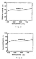
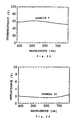
- the transmission profile of the low-transmission transparent layer formed in Example 1 is shown in Fig. 1 and Fig. 3.
- Example 2 By following the same procedure as Example 1 except that using 0.35 g of the liquid A and 2.10 g of the liquid B prepared in Example 1, a low-transmission transparent layer forming coating liquid containing the composite oxide fine particles of iron, manganese, and copper and the inorganic binder (Fe-Mn-Cu-O: 0.70%, SiO 2 : 2.10%, water: 4.78%, EA: 53.44%, IPA: 6.82%, and PGM: 30%) was prepared, a glass substrate having formed thereon a low-transmission transparent layer containing the composite oxide fine particles of iron, manganese, and copper and the binder matrix, that is, the low-transmission transparent layered structure of Example 2 was obtained.
- a low-transmission transparent layer forming coating liquid containing the composite oxide fine particles of iron, manganese, and copper and the inorganic binder Fe-Mn-Cu-O: 0.70%, SiO 2 : 2.10%, water: 4.78%, EA: 53.44%, IPA: 6.
- the film characteristics of the low-transmission transparent layer formed on the glass substrate are shown in Table 1 below. Also, the transmission profile of the low-transmission transparent layer in Example 2 produced is shown in Fig. 4.
- Example 3 By following the same procedure as Example 1 except that using 0.35 g of the liquid A and 2.80 g of the liquid B prepared in Example 1, a low-transmission transparent layer forming coating liquid containing the composite oxide fine particles of iron, manganese, and copper and the inorganic binder (Fe-Mn-Cu-O: 0.70%, SiO 2 : 2.80%, water: 5.48%, EA: 52.41%, IPA: 5.77%, and PGM: 30%) was prepared, a glass substrate having formed thereon a low-transmission transparent layer containing the composite oxide fine particles of iron, manganese, and copper and the binder matrix, that is, the low-transmission transparent layered structure of Example 3 was obtained.
- a low-transmission transparent layer forming coating liquid containing the composite oxide fine particles of iron, manganese, and copper and the inorganic binder Fe-Mn-Cu-O: 0.70%, SiO 2 : 2.80%, water: 5.48%, EA: 52.41%, IPA: 5.77%
- the film characteristics of the low-transmission transparent layer formed on the glass substrate are shown in Table 1 below. Also, the transmission profile of the low-transmission transparent layer in Example 3 produced is shown in Fig. 5.
- Example 2 By following the same procedure as Example 1 except that using carbon fine particles (MA-7, trade name, manufactured by Mitsubishi Chemical Corporation) were used in place of the composite oxide fine particles of iron, manganese, and copper in Example 1, a low-transmission transparent layer forming coating liquid containing the carbon fine particles and the inorganic binder (carbon: 0.30%, SiO 2 : 0.60%, water: 3.88%, EA: 4.21%, IPA: 88.66%, and PGM: 5.0%) was prepared, a glass substrate having formed thereon a low-transmission transparent layer containing the carbon fine particles and the binder matrix, that is, the low-transmission transparent layered structure of Comparative Example 1 was obtained.
- carbon fine particles MA-7, trade name, manufactured by Mitsubishi Chemical Corporation
- the film characteristics of the low-transmission transparent layer formed on the glass substrate are shown in Table 1 below. Also, the transmission profile of the low-transmission transparent layer in Comparative Example 1 produced is shown in Fig. 1.
- Example 2 By following the same procedure as Example 1 except that using 0.35 g of the liquid A and 0.70 g of the liquid B prepared in Example 1, a low-transmission transparent layer forming coating liquid containing the composite oxide fine particles of iron, manganese, and copper and the inorganic binder (Fe-Mn-Cu-O: 0.70%, SiO 2 : 0.70%, water: 2.88%, EA: 55.50%, IPA: 8.92%, and PGM: 30.0%) was prepared, a glass substrate having formed thereon a low-transmission transparent layer containing composite oxide fine particles of iron, manganese, and copper and the binder matrix, that is, the low-transmission transparent layered structure of Comparative Example 2 was obtained.
- a low-transmission transparent layer forming coating liquid containing the composite oxide fine particles of iron, manganese, and copper and the inorganic binder Fe-Mn-Cu-O: 0.70%, SiO 2 : 0.70%, water: 2.88%, EA: 55.50%,
- the film characteristics of the low-transmission transparent layer formed on the glass substrate are shown in Table 1 below. Also, the transmission profile of the low-transmission transparent layer in Comparative Example 2 produced is shown in Fig. 6.
- Example 2 The same procedure as Example 1 was followed except that using 0.35 g of the liquid A and 4.90 g of the liquid B prepared in Example 1, a low-transmission transparent layer forming coating liquid containing the composite oxide fine particles of iron, manganese, and copper and the inorganic binder (Fe-Mn-Cu-O: 0.70%, SiO 2 : 4.90%, water: 7.58%, EA: 49.32%, IPA: 2.63%, and PGM: 30.0%) was prepared, but because the low-transmission transparent layer was peeled off from the glass substrate at a heating treatment at 180°C for 30 minutes after spin coating the layer, a low-transmission transparent layered structure could not be obtained.
- a low-transmission transparent layer forming coating liquid containing the composite oxide fine particles of iron, manganese, and copper and the inorganic binder Fe-Mn-Cu-O: 0.70%, SiO 2 : 4.90%, water: 7.58%, EA: 49.32%, IPA: 2.6
- the mean particle size of the composite oxide fine particles of iron, manganese, and copper was 48 nm.
- IPA and n-butanol NBA
- the film characteristics (the surface resistance, the transmission, the standard deviation of the transmission, the haze value, and bottom reflectance/bottom wavelength) of the double layer film formed on the glass substrate are shown in Table 3 below.
- bottom reflectance means the minimum reflectance of a low-transmission transparent layered structure in the reflection profile and the term “bottom wavelength” means the wavelength in the minimum reflectance.
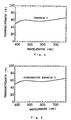
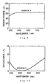
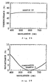
- the reflection profile of the low-transmission transparent layered structure obtained in Example 4 is shown in Fig. 2 and Fig. 8 and the transmission profile thereof is shown in Fig. 7 and Fig. 9.
- Example 5 By following the same procedure as Example 4 except that curing was carried out at 450°C for 30 minutes, a glass substrate having formed thereon a double layer film constituted of a low-transmission transparent layer containing composite fine particles of iron, manganese, and copper and a transparent coat layer composed of a silicate film made of silicon oxide as the main constituent, that is, the low-transmission transparent layered structure of Example 5 was obtained.
- the film characteristics of the double layer film formed on the glass substrate are shown in Table 3 below. Furthermore, the reflection profile of the low-transmission transparent layered structure of Example 5 produced is shown in Fig. 10 and the transmission profile thereof is shown in Fig. 11.
- Example 4 By following the same procedure as Example 4 except that by mixing 0.35 g of the liquid C of Example 4 and 0.7 g of the liquid B in Example 1, a coating liquid having dispersed therein composite oxide fine particles of iron, manganese, and copper having a dispersed particle size of 98 nm (Fe-Mn-Cu-O: 0.70%, SiO 2 : 0.70%, water: 3.40%.
- EA 55.60%, IPA: 8.90%, and PGM: 30.0%
- a glass substrate having formed thereon a double layer film constituted of a low-transmission transparent layer containing the composite oxide fine particles of iron, manganese, and, copper and a transparent coat layer composed of a silicate film made of silicon oxide as the main constituent, that is, the low-transmission transparent layered structure of Example 6 was obtained.
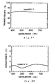
- the film characteristics of the double layer film formed on the glass substrate are shown in Table 3 below. Also, the reflection profile of the low-transmission transparent layered structure of Example 6 produced is shown in Fig. 12 and the transmission profile thereof is shown in Fig. 13.
- Example 4 By following the same procedure as Example 4 except that using carbon fine particles (MA-7, trade name, manufactured by Mitsubishi Chemical Corporation) in place of the composite oxide fine particles of iron, manganese, and copper in Example 4, a low-transmission transparent layer forming coating liquid having dispersed therein the carbon fine particles having a dispersed particle size of 40 nm (carbon: 0.30%, EA: 57.0%, IPA: 12.70%, and PGM: 30.0%) was prepared, a glass substrate having formed thereon a double layer film constituted of a low-transmission transparent layer containing the carbon fine particles and a transparent coat layer composed of a silicate film made of silicon oxide as the main constituent, that is, the low-transmission transparent layered structure of Comparative Example 4 was obtained.
- carbon fine particles MA-7, trade name, manufactured by Mitsubishi Chemical Corporation
- the film characteristics of the low-transmission transparent layer formed on the glass substrate are shown in Table 3 below. Also, the reflection profile of the low-transmission transparent layered structure of Comparative Example 4 produced is shown in Fig. 2, and the transmission profile thereof is shown in Fig. 7.
- Example 5 By following the same procedure as Example 4 except that the transparent coat layer composed of the silicate film made of silicon oxide as the main constituent in Example 4 was not formed, a glass substrate having formed thereon a low-transmission transparent layer made of a single layer film constituted of a low-transmission transparent layer containing composite oxide fine particles of iron, manganese, and copper, that is, the low-transmission transparent layered structure of Comparative Example 5 was obtained.
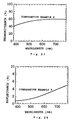
- the film characteristics of the low-transmission transparent layer formed on the glass substrate are shown in Table 3 below. Also, the reflection profile of the low-transmission transparent layered structure of Comparative Example 5 produced is shown in Fig. 14, and the transmission profile thereof is shown in Fig. 15.
- Titanium hydroxide obtained by hydrolyzing titanium chloride with an aqueous alkali solution was treated in an ammonia gas at 800°C to obtain black titanium oxynitride fine particles (nitrogen: 15.5%).
- a low- transmission transparent layer forming coating liquid a containing the carbon fine particles and the black titanium compound fine particles (carbon: 0.16%, black titanium oxynitride: 0.30%, water: 2.64%, EA: 55.59%, IPA: 11.23%, and PGM: 30.0%) was prepared.
- the mean particle size of each of the carbon fine particles and the black titanium fine particles was 40 nm and 55 nm, respectively.
- Example 7 by following the same procedure as Example 4 except that the low-transmission transparent layer forming coating liquid containing the carbon fine particles and the black titanium compound fine particles was used, a glass substrate having formed thereon a double layer film constituted of the low-transmission transparent layer containing the carbon fine particles and the black titanium compound fine particles and a transparent coat layer composed of a silicate layer made of silicon oxide as the main constituent, that is, the low-transmission transparent layered structure of Example 7 was obtained.
- the film characteristics (the surface resistance, the transmission, the standard deviation of the transmission, the haze value, and bottom reflectance/bottom wavelength) of the double layer film formed on the glass substrate are shown in Table 5 below. Also, the reflection profile of the low-transmission transparent layered structure of Example 7 is shown in Fig. 16 and Fig. 18, and the transmission profile thereof is shown in Fig. 17 and Fig. 19.
- Example 8 By following the same procedure as Example 7 except that using 0.45 g of the liquid D and 0.08 g of the liquid E each prepared in Example 7, a low-transmission transparent layer forming coating liquid containing the carbon fine particles and the black titanium compound fine particles (carbon: 0.08%, black titanium oxynitride: 0.45%, water: 3.96%, EA: 55.0%, IPA: 10.41%, and PGM: 30.0%) was prepared, a glass substrate having formed thereon a double layer film constituted of a low-transmission transparent layer containing the carbon fine particles and the black titanium compound fine particles and a transparent coat layer composed of a silicate film made of silicon oxide as the main constituent, that is, the low-transmission transparent layered structure of Example 8 was obtained.
- the film characteristics of the double layer film formed on the glass substrate are shown in Table 5 below. Also, the reflection profile of the low-transmission transparent layered structure of Example 8 is shown in Fig. 20 and the transmission profile thereof is shown in Fig. 21.
- Example 7 By following the same procedure as Example 7 except that after mixing 8 g of black titanium sub-oxide (Tilack D, trade name, manufactured by Ako Kasei Co., Ltd.) with 0.7 g of a dispersing agent and 71.3 g of diacetone alcohol (DAA), the mixture was dispersed with zirconia beads in a paint shaker to obtain a dispersion (liquid F) of the black titanium oxide fine particles having a dispersed particle size of 125 nm, and using 1.8 g of the liquid F and 0.08 g of the liquid E, a low-transmission transparent layer forming coating liquid containing the carbon fine particles and the black titanium compound fine particles (carbon: 0.08%, black titanium oxide: 1.80%, EA: 43.52%, IPA: 8.39%, DAA: 16.04%, and PGM: 30.0%) was prepared, a glass substrate having formed thereon a double layer film constituted of a low-transmission transparent layer containing the carbon fine particles and the black titanium compound fine particles and a
- the film characteristics of the double layer film formed on the glass substrate are shown in Table 5 below. Also, the reflection profile of the low-transmission transparent layered structure of Example 9 is shown in Fig. 22 and the transmission profile thereof is shown in Fig. 23.
- Example 7 By following the same procedure as Example 7 except that by mixing 0.3 g of the liquid D and 0.16 g of the liquid E in Example 7 with 0.46 g of the liquid B in Example 1, a low- transmission transparent layer forming coating liquid containing the carbon fine particles, the black titanium compound fine particles, and the silica sol (carbon: 0.16%, black titanium oxynitride: 0.30%, SiO 2 : 0.46%, water: 3.10%, EA: 54.91%, IPA: 10.54%, and PGM: 30.0%) was prepared, a glass substrate having formed thereon a double layer film constituted of a low-transmission transparent layer containing the carbon fine particles and the black titanium compound fine particles and a transparent coat layer composed of a silicate film made of silicon oxide as the main constituent, that is, the low-transmission transparent layered structure of Example 10 was obtained.
- the film characteristics of the double layer film formed on the glass substrate are shown in Table 5 below. Also, the reflection profile of the low-transmission transparent layered structure of Example 10 is shown in Fig. 24 and the transmission profile thereof is shown in Fig. 25.
- Example 7 By following the same procedure as Example 7 except that using carbon fine particles (MA-7, trade name, manufactured by Mitsubishi Chemical Corporation) in place of the carbon fine particles and the black titanium compound fine particles used in Example 7, a low-transmission transparent layer forming coating liquid having dispersed therein the carbon fine particles having a dispersed particle size of 40 nm (carbon: 0.32%, EA: 56.78%, IPA: 11.95%, and PGM: 30.0%) was prepared, a glass substrate having formed thereon a double layer film constituted of a low-transmission transparent layer containing the carbon fine particles and a transparent coat layer composed of a silicate film made of silicon oxide as the main constituent, that is, the low-transmission transparent layered structure of Comparative Example 6 was obtained.
- carbon fine particles MA-7, trade name, manufactured by Mitsubishi Chemical Corporation
- the film characteristics of the double layer film formed on the glass substrate are shown in Table 5 below. Also, the reflection profile of the low-transmission transparent layered structure of Comparative Example 6 is shown in Fig. 16 and the transmission profile thereof is shown in Fig. 17.
- Example 7 By following the same procedure as Example 7 except that using the black titanium oxynitride fine particles used in Example 7 in place of the carbon fine particles and the black titanium compound fine particles in Example 7, a low-transmission transparent layer forming coating liquid having dispersed therein the black titanium oxynitride fine particles having a dispersed particle size of 55 nm (black titanium oxynitride fine particles: 0.60%, water: 5.28%, EA: 54.40%, IPA: 9.60%, and PGM: 30.0%) was prepared, a glass substrate having formed thereon a double layer film constituted of a low-transmission transparent layer containing the black titanium oxynitride fine particles and a transparent coat layer composed of a silicate film made of silicon oxide as the main constituent, that is, the low-transmission transparent layered structure of Comparative Example 7 was obtained.
- the film characteristics of the double layer film formed on the glass substrate are shown in Table 5 below. Also, the reflection profile of the low-transmission transparent layered structure of Comparative Example 7 is shown in Fig. 16 and the transmission profile thereof is shown in Fig. 17.
- Example 7 By following the same procedure as Example 7 except that using 0.15 g of the liquid D and 0.24 g of the liquid E each prepared in Example 7, a low-transmission transparent layer forming coating liquid containing the carbon fine particles and the black titanium compound fine particles (carbon: 0.24%, black titanium oxynitride: 0.15%, water: 1.32%, EA: 56.19%, IPA: 12.04%, and PGM: 30.0%) was prepared, a glass substrate having formed thereon a double layer film constituted of a low-transmission transparent layer containing the carbon fine particles and the black titanium compound fine particles and a transparent coat layer composed of a silicate film made of silicon oxide as the main constituent, that is, the low-transmission transparent layered structure of Comparative Example 8 was obtained.
- a glass substrate having formed thereon a double layer film constituted of a low-transmission transparent layer containing the carbon fine particles and the black titanium compound fine particles and a transparent coat layer composed of a silicate film made of silicon oxide as the main constituent that is, the
- the film characteristics of the double layer film formed on the glass substrate are shown in Table 5 below. Also, the reflection profile of the low-transmission transparent layered structure of Comparative Example 8 is shown in Fig. 26 and the transmission profile thereof is shown in Fig. 27.
- Example 9 By following the same procedure as Example 7 except that the formation of the transparent coat layer composed of the silicate film made of silicon oxide as the main constituent in Example 7 was not carried out, the glass substrate having formed thereon a low-transmission transparent layer made of a single layer film containing the carbon fine particles and the black titanium compound fine particles, that is, the low-transmission transparent layered structure of Comparative Example 9 was obtained.
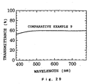
- the film characteristics of the single layer film formed on the glass substrate are shown in Table 5 below. Also, the reflection profile of the low-transmission transparent layered structure of Comparative Example 9 is shown in Fig. 28 and the transmission profile thereof is shown in Fig. 29.
- Each of the low-transmission transparent layered structures obtained in Examples 7 to 10 was immersed in an aqueous solution of 10% sodium chloride, an aqueous solution of 50% acetic acid, and an aqueous solution of 5% ammonia for 24 hours, and the transmission and the appearance of the each low-transmission transparent layer formed on the transparent substrate (glass substrate) were investigated but the changes were not observed in each case.
- the mixture was dispersed with zirconia beads in a paint shaker to obtain a dispersion (liquid G) of the ATO fine particles having a dispersed particle size of 45 nm.
- a low-transmission transparent layer forming coating liquid containing the composite oxide fine particles of iron, manganese, and copper, the ATO fine particles, and the inorganic binder (Fe-Mn-Cu-O: 0.80%, ATO: 3.36%, SiO 2 : 4.80%, water: 7.3%, EA: 72.1%, and IPA: 11.6%) was prepared.
- Example 11 a glass substrate having formed thereon a low-transmission transparent layer, that is, the low-transmission transparent layered structure of Example 11 was obtained.
- Example 12 by following the same procedure as Example 4 using the low-transmission transparent layer forming coating liquid containing the composite oxide fine particles of iron, manganese, and copper and the ATO fine particles, a glass substrate having formed thereon a double layer film constituted of the low-transmission transparent layer containing the composite oxide fine particles of iron, manganese, and copper and the ATO fine particles and a transparent coat layer composed of a silicate film made of silicon oxide as the main constituent, that is, the low-transmission transparent layered structure of Example 12 was obtained.
- Example 12 By following the same procedure as Example 12 except that using 0.6 g of the liquid G in Example 12 and 0.25 g of the liquid A in Example 1, a low-transmission transparent layer forming coating liquid containing the composite oxide fine particles of iron, manganese, and copper and the ATO fine particles (Fe-Mn-Cu-O: 0.5%, ATO: 1.2%, water: 1.5%, EA: 4.7%, PGM: 87.1%, and DAA: 5.0%) was prepared, a glass substrate having formed thereon a double layer film constituted of the low-transmission transparent layer containing the composite oxide fine particles of iron, manganese, and copper and the ATO fine particles and a transparent coat layer composed of a silicate film made of silicon oxide as the main constituent, that is, a low-transmission transparent layered structure of Example 13 was obtained.
- the film characteristics of the double layer film formed on the glass substrate are shown in Table 7 below.
- ITO fine particles having a mean particle size of 30 nm (SUFP-HX, trade name, manufactured by SUMITOMO METAL MINING CO., LTD.) with 1.5 g of a dispersing agent and 78.5 g of EA, the mixture was dispersed with zirconium beads in a paint shaker, a dispersion (liquid H) of the ITO fine particles having a dispersed particle size of 105 nm was obtained.
- a low-transmission transparent layer forming coating liquid for forming a low-transmission transparent layer containing the carbon fine particles, the black titanium oxynitride fine particles, the ITO fine particles, and the silica sol carbon: 0.16%, black titanium oxynitride: 0.30%, ITO: 0.8%, SiO 2 : 0.46%, water: 2.90%, EA: 6.4%, IPA: 1.4%, PGM: 82.5%, and DAA: 5.0%) was prepared, a glass substrate having formed thereon a double layer film constituted of the low-transmission transparent layer containing the carbon fine particles, the black titanium oxynitride fine particles, and the ITO fine particles and a transparent coat layer composed of a silicate
- a low-transmission transparent layered structure which has a flat transmission profile, can provide a low reflectance and antistatic and electric field shielding functions, and further can reduce the production cost, and the production method of the low-transmission transparent layered structure are provided and also a display device to which the low-transmission transparent layered structure is applied can be provided.
Landscapes
- Chemical & Material Sciences (AREA)
- Life Sciences & Earth Sciences (AREA)
- Engineering & Computer Science (AREA)
- Chemical Kinetics & Catalysis (AREA)
- General Chemical & Material Sciences (AREA)
- Geochemistry & Mineralogy (AREA)
- Materials Engineering (AREA)
- Organic Chemistry (AREA)
- Dispersion Chemistry (AREA)
- Composite Materials (AREA)
- Laminated Bodies (AREA)
- Paints Or Removers (AREA)
- Optical Filters (AREA)
- Optical Elements Other Than Lenses (AREA)
- Surface Treatment Of Glass (AREA)
- Devices For Indicating Variable Information By Combining Individual Elements (AREA)
Abstract
Description
- B: The transmission of only the double layer film without containing the transparent substrate.
- C': The transmission of the double layer film together with the transparent substrate.
- D: The transmission of the transparent substrate.
| Kind of fine particles | Amount of binder matrix () | Visible light transmission (%) | Standard deviation of transmission () | Haze value (%) | |
| E1 | Fe-Mn-Cu-O | 200 | 57.9 | 3.84 | 0.8 |
| E2 | Fe-Mn-Cu-O | 300 | 57.4 | 3.36 | 0.6 |
| E3 | Fe-Mn-Cu- | 400 | 58.0 | 3.78 | 0.6 |
| CE1 | Carbon | 200 | 57.2 | 6.55 | 1.0 |
| CE2 | Fe-Mn-Cu- | 100 | 59.9 | 3.28 | 1.0 |
| CE3 | Fe-Mn-Cu- | 700 | peel | peel | peel |
| E: Example, CE: Comparative Example |
| Visible Light Transmission (%) | low-transmission transparent layer | ||
| Initial value | Value after immersing in aqueous 50% acetic acid solution | ||
| Example 1 | 57.9 | 60.8 | No change |
| Example 2 | 57.4 | 57.9 | No change |
| Example 3 | 58.0 | 58.6 | No change |
| Comparative Example 2 | 59.9 | 83.4 | Brownish discolored |
| Kind of fine particles | Transmission of visible light (%) | Standard deviation of transmission () | Haze value (%) | Bottom reflectance (%)/bottom wavelength (nm) | |
| E4 | Fe-Mn-Cu-O | 62.7 | 3.55 | 0.6 | 0.29/590 |
| E5 | Fe-Mn-Cu-O | 62.4 | 2.88 | 0.6 | 0.13/520 |
| E6 | Fe-Mn-Cu-O | 60.2 | 3,78 | 1.0 | 2.24/675 |
| CE4 | Carbon | 57.1 | 8.94 | 0.6 | 0.29/620 |
| CE5 | Fe-Mn-Cu-O | 58.9 | 2.58 | 1.0 | - |
| E: Example, CE: Comparative Example |
| Visible Light Transmission (%) | Appearance of double layer film or single layer film | ||
| Initial value | Value after immersing in aqueous 50% acetic acid solution | ||
| Example 4 | 62.7 | 64.9 | No change |
| Example 5 | 62.4 | 68.2 | No change |
| Example 6 | 60.2 | 62.0 | No change |
| Comparative Example 5 | 58.9 | 87.5 | Brownish discolored |


| Pencil Hardness | |
| Example 7 | 7H |
| Example 8 | 7H |
| Example 9 | 7H |
| Example 10 | 7H |
| Comparative Example 9 | < H |

| Transmission % | Appearance of double layer film | ||
| Initial value | Value after immersing in aqueous 50% acetic acid solution | ||
| Example 11 | 55.0 | 58.4 | No change |
| Example 12 | 62.9 | 63.9 | No change |
| Example 13 | 77.7 | 78.2 | No change |
| Example 14 | 65.3 | 65.4 | No change |
Claims (20)
- A low-transmission transparent layered structure comprising a transparent substrate and a low-transmission transparent layer formed on the transparent substrate, wherein the low-transmission transparent layer is constituted of black pigment fine particles having a mean particle size of from 10 to 150 nm and a binder matrix as the main constituents, the black pigment fine particles being composite oxide fine particles of iron, manganese, and copper, or are carbon fine particles and black titanium compound fine particles, the visible light transmission of the low-transmission transparent layer is from 40 to 90%, and the standard deviation of the transmission of the low-transmission transparent layer in each wavelength every 5 nm of a visible light wavelength region (380 to 780 nm) is 5% or lower.
- The low-transmission transparent layered structure according to claim 1 wherein the black titanium compound is black titanium oxide or black titanium oxynitride.
- The low-transmission transparent layered structure according to claim 1 or 2 wherein the mixing ratio of the black titanium compound fine particles to the carbon fine particles is from 80 to 2500 parts by weight of the black titanium compound fine particles to 100 parts by weight of the carbon fine particles.
- The low-transmission transparent layered structure according to any of claims 1 to 3 wherein the constituting ratio of the binder matrix to the black pigment fine particles in the low-transmission transparent layer is from 150 to 650 parts by weight of the binder matrix to 100 parts by weight of the black pigment fine particles.
- The low-transmission transparent layered structure according to any of claims 1 to 4 wherein the low-transmission transparent layer contains an electrically conductive oxide fine particles having a mean particle size of from 10 to 150 nm, the compounded amount of the electrically conductive oxide fine particles is from 50 to 1000 parts by weight to 100 parts by weight of the black pigment fine particles, and the surface resistance of the low-transmission transparent layer is from 104 to 1010 Ω/square.
- The low-transmission transparent layered structure according to claim 5 wherein the electrically conductive oxide fine particles are at least one kind of fine particles selected from indium tin oxide fine particles and tin antimony oxide fine particles.
- The low-transmission transparent layered structure according to any of claims 1 to 4 wherein the low-transmission transparent layered structure is a low-transmission transparent layered structure having a double layer film formed by forming on the transparent substrate the low-transmission transparent layer and further a transparent coat layer, the reflectance of the low-transmission transparent layered structure, which becomes minimum in the reflection profile of a visible light region, is 3% or lower, the visible light transmission of the double layer film is from 40 to 90%, and further the standard deviation of the transmission of the double layer film in each wavelength every 5 nm of a visible light wavelength region (380 to 780 nm) is 5% or lower.
- The low-transmission transparent layered structure according to claim 5 or 6 wherein the low-transmission transparent layered structure is a low-transmission transparent layered structure having a double layer film formed by forming on the transparent substrate the low-transmission transparent layer containing the electrically conductive fine particles and further a transparent coat layer, the reflectance of the low-transmission transparent layered structure, which becomes the minimum in the reflection profile of a visible light region, is 3% or lower, the surface resistance and the visible light transmission of the double layer film are from 104 to 1010 Ω/square and from 40 to 90%, respectively, and further, the reflectance of the low-transmission transparent layered structure, which becomes the minimum in the reflection profile of a visible light region, is 3% or lower, the visible light transmission of the double layer film is from 40 to 90%, and further the standard deviation of the transmission of the double layer film in each wavelength every 5 nm of a visible light wavelength region (380 to 780 nm) is 5% or lower.
- The low-transmission transparent layered structure according to any of claims 1 to 8 wherein each of the binder matrix in the low-transmission transparent layer and the transparent coat layer is made of silicon oxide as the main constituent.
- A method of producing a low-transmission transparent layered structure, which comprises preparing a low-transmission transparent layer forming coating liquid by dispersing black pigment fine particles having a mean particle size of from 10 to 150 nm made of composite oxide fine particles of iron, manganese, and copper, or made of carbon fine particles and black titanium compound fine particles, and an inorganic binder constituting a binder matrix in a solvent as the main constituents, and, after coating the low-transmission transparent layer forming coating liquid on a transparent substrate, heat-treating the coated layer.
- The method of producing a low-transmission transparent layered structure according to claim 10 wherein the constituting ratio of the inorganic binder to the black pigment fine particles in the low-transmission transparent layer forming coating liquid is from 150 to 650 parts by weight of the inorganic binder to 100 parts by weight of the black pigment fine particles.
- The method of producing a low-transmission transparent layered structure according to claim 10 or 11 wherein the low-transmission transparent layer forming coating liquid contains electrically conductive oxide fine particles having a mean particle size of from 10 to 150 nm and the compounding amount of the electrically conductive fine particles is from 50 to 1000 parts by weight to 100 parts by weight of the electrically conductive oxide fine particles.
- A method of producing a low-transmission transparent layered structure, which comprises preparing a low-transmission transparent layer forming coating liquid by dispersing black pigment fine particles having a mean particle size of from 10 to 150 nm made of composite oxide fine particles of iron, manganese, and copper, or made of carbon fine particles and black titanium compound fine particles in a solvent as the main constituent, coating the low-transmission transparent layer forming coating liquid on a transparent substrate, and then, after further coating thereon a transparent coat layer forming coating liquid, heat-treating the coated layers.
- The method of producing a low-transmission transparent layered structure according to claim 13 wherein the low-transmission transparent layer forming coating liquid further contains electric conductive oxide fine particles having a mean particle size of from 10 to 150 nm, and the compounded amount of the electrically conductive fine particles is from 50 to 1000 parts by weight to 100 parts by weight of the black pigment fine particles.
- The method of producing a low-transmission transparent layered structure according to claim 13 or 14 wherein the low-transmission transparent layer forming coating liquid further contains an inorganic binder constituting a binder matrix.
- The method of producing a low-transmission transparent layered structure according to any of claims 12 to 15 wherein the electrically conductive oxide fine particles are at least one kind of fine particles selected from indium tin oxide fine particles and tin antimony oxide fine particles.
- The method of producing a low-transmission transparent layered structure according to any of claims 10 to 16 wherein the black titanium compound is black titanium oxide or black titanium oxynitride.
- The method of producing a low-transmission transparent layered structure according to any of claims 10 to 17 wherein the compounding ratio of the black titanium compound fine particles the carbon fine particles is from 80 to 2500 parts by weight of the black titanium compound fine particles to 100 parts by weight of the carbon fine particles.
- The method of producing a low-transmission transparent layered structure according to any of claims 10 to 18 wherein the inorganic binder of the low-transmission transparent layer forming coating liquid and the transparent coat layer forming the coating liquid and the coating liquid is made of a silica sol as the main constituent
- A display device comprising a main body and a front face plate disposed at the front face side of the main body, wherein the low-transmission transparent layered structure described in any of claims 1 to 9 is incorporated therein by disposing with the low-transmission transparent layer side thereof outside as the front face plate.
Applications Claiming Priority (8)
| Application Number | Priority Date | Filing Date | Title |
|---|---|---|---|
| JP871899 | 1999-01-18 | ||
| JP885199 | 1999-01-18 | ||
| JP885199 | 1999-01-18 | ||
| JP879099 | 1999-01-18 | ||
| JP879099 | 1999-01-18 | ||
| JP871899 | 1999-01-18 | ||
| JP11354757A JP2000275409A (en) | 1999-01-18 | 1999-12-14 | Low-transmission transparent base material, its manufacture, and display device employing the same |
| JP35475799 | 1999-12-14 |
Publications (3)
| Publication Number | Publication Date |
|---|---|
| EP1020891A2 true EP1020891A2 (en) | 2000-07-19 |
| EP1020891A3 EP1020891A3 (en) | 2001-05-23 |
| EP1020891B1 EP1020891B1 (en) | 2004-12-29 |
Family
ID=27455009
Family Applications (1)
| Application Number | Title | Priority Date | Filing Date |
|---|---|---|---|
| EP00300328A Expired - Lifetime EP1020891B1 (en) | 1999-01-18 | 2000-01-18 | Low-transmission transparent layered structure |
Country Status (4)
| Country | Link |
|---|---|
| US (1) | US6423404B1 (en) |
| EP (1) | EP1020891B1 (en) |
| JP (1) | JP2000275409A (en) |
| DE (1) | DE60016983T2 (en) |
Cited By (6)
| Publication number | Priority date | Publication date | Assignee | Title |
|---|---|---|---|---|
| EP1205961A1 (en) * | 2000-11-09 | 2002-05-15 | Matsushita Electric Industrial Co., Ltd. | Method of treating surface of face panel used for image display device, and image display device comprising the treated face panel |
| EP1104000A3 (en) * | 1999-11-25 | 2003-11-26 | Sumitomo Metal Mining Company Limited | Transparent conductive layered structure, display in which this transparent conductive layered structure is applied, and coating liquid for forming transparent conductive layer |
| EP1079413A3 (en) * | 1999-08-26 | 2003-11-26 | Sumitomo Metal Mining Company Limited | Transparent conductive layered structure and method of producing the same, coating liquid useful therefor, and display that uses transparent conductive layered structure |
| EP1391910A3 (en) * | 2002-08-14 | 2004-07-28 | Thomson Licensing S.A. | Crt having a contrast enhancing exterior coating and method of manufacturing the same |
| EP1862437A1 (en) * | 2006-05-30 | 2007-12-05 | Nippon Sheet Glass Company Limited | Transparent article with infrared shielding film |
| CN108912395A (en) * | 2017-04-07 | 2018-11-30 | 明尼苏达矿业制造特殊材料(上海)有限公司 | Mixture of nanoparticles, polymer, pad pasting and thermal isolation film |
Families Citing this family (10)
| Publication number | Priority date | Publication date | Assignee | Title |
|---|---|---|---|---|
| JP2002014421A (en) * | 2000-06-28 | 2002-01-18 | Seiko Epson Corp | Electro-optical device and projector |
| WO2005111674A1 (en) * | 2004-05-13 | 2005-11-24 | Showa Denko K.K. | Black resist composition for color filter |
| JP2007121560A (en) * | 2005-10-26 | 2007-05-17 | Dainippon Toryo Co Ltd | Visible light adjustment filter |
| JP2010107946A (en) * | 2008-07-04 | 2010-05-13 | Jsr Corp | Nd filter and process for producing the same |
| JP2010156765A (en) * | 2008-12-26 | 2010-07-15 | Jsr Corp | Nd filter, method of manufacturing the same and method of controlling transmittance of light using them |
| JP5310478B2 (en) * | 2008-10-24 | 2013-10-09 | Jsr株式会社 | Manufacturing method of ND filter |
| WO2014086487A1 (en) * | 2012-12-04 | 2014-06-12 | Ingo Stork Genannt Wersborg | Heat treatment device with monitoring system |
| WO2018093985A1 (en) | 2016-11-17 | 2018-05-24 | Cardinal Cg Company | Static-dissipative coating technology |
| US10629385B2 (en) * | 2017-07-24 | 2020-04-21 | The Board Of Trustees Of The University Of Arkansas | Hierarchically nanostructured films and applications thereof |
| CN119744081B (en) * | 2024-12-11 | 2025-10-10 | 武汉华星光电半导体显示技术有限公司 | organic electroluminescent panels |
Family Cites Families (9)
| Publication number | Priority date | Publication date | Assignee | Title |
|---|---|---|---|---|
| US5291097A (en) * | 1990-05-14 | 1994-03-01 | Hitachi, Ltd. | Cathode-ray tube |
| EP0533030B1 (en) * | 1991-09-20 | 1995-06-21 | Hitachi, Ltd. | Method and apparatus for forming an anti-reflection film for a cathode-ray tube |
| DE69309814T2 (en) * | 1992-08-31 | 1997-10-16 | Sumitomo Cement Co | Antireflective and antistatic clothing layer for an electron beam tube |
| EP0603941B1 (en) * | 1992-12-21 | 1997-04-02 | Koninklijke Philips Electronics N.V. | Display device comprising a display screen provided with a filtering layer |
| TW358118B (en) * | 1993-10-08 | 1999-05-11 | Toshiba Co Ltd | Display and the manufacturing method |
| WO1996005606A1 (en) * | 1994-08-08 | 1996-02-22 | Philips Electronics N.V. | Cathode ray tube comprising a display screen having an electroconductive coating |
| IT1277470B1 (en) * | 1995-08-09 | 1997-11-10 | Videocolor Spa | MANUFACTURING PROCESS OF A CATHODE-BEAMED TUBE EQUIPPED WITH ANTI-GLARE AND ANTI-DARK FRONT PLATE COVERING |
| US6001533A (en) * | 1996-03-27 | 1999-12-14 | Dai Nippon Printing Co., Ltd. | Composition for forming non-conductive light-shielding layer, and non-conductive light-shielding layer containing same |
| JP3884110B2 (en) * | 1996-10-09 | 2007-02-21 | 株式会社東芝 | Cathode ray tube |
-
1999
- 1999-12-14 JP JP11354757A patent/JP2000275409A/en active Pending
-
2000
- 2000-01-18 US US09/484,543 patent/US6423404B1/en not_active Expired - Fee Related
- 2000-01-18 EP EP00300328A patent/EP1020891B1/en not_active Expired - Lifetime
- 2000-01-18 DE DE60016983T patent/DE60016983T2/en not_active Expired - Fee Related
Cited By (8)
| Publication number | Priority date | Publication date | Assignee | Title |
|---|---|---|---|---|
| EP1079413A3 (en) * | 1999-08-26 | 2003-11-26 | Sumitomo Metal Mining Company Limited | Transparent conductive layered structure and method of producing the same, coating liquid useful therefor, and display that uses transparent conductive layered structure |
| EP1104000A3 (en) * | 1999-11-25 | 2003-11-26 | Sumitomo Metal Mining Company Limited | Transparent conductive layered structure, display in which this transparent conductive layered structure is applied, and coating liquid for forming transparent conductive layer |
| KR100689699B1 (en) * | 1999-11-25 | 2007-03-08 | 스미토모 긴조쿠 고잔 가부시키가이샤 | Transparent conductive layer structure and the display solution to which the transparent conductive layer structure is applied and coating liquid for forming transparent conductive layer |
| EP1205961A1 (en) * | 2000-11-09 | 2002-05-15 | Matsushita Electric Industrial Co., Ltd. | Method of treating surface of face panel used for image display device, and image display device comprising the treated face panel |
| EP1391910A3 (en) * | 2002-08-14 | 2004-07-28 | Thomson Licensing S.A. | Crt having a contrast enhancing exterior coating and method of manufacturing the same |
| US7166957B2 (en) | 2002-08-14 | 2007-01-23 | Thomson Licensing | CRT having a contrast enhancing exterior coating and method of manufacturing the same |
| EP1862437A1 (en) * | 2006-05-30 | 2007-12-05 | Nippon Sheet Glass Company Limited | Transparent article with infrared shielding film |
| CN108912395A (en) * | 2017-04-07 | 2018-11-30 | 明尼苏达矿业制造特殊材料(上海)有限公司 | Mixture of nanoparticles, polymer, pad pasting and thermal isolation film |
Also Published As
| Publication number | Publication date |
|---|---|
| EP1020891B1 (en) | 2004-12-29 |
| DE60016983D1 (en) | 2005-02-03 |
| DE60016983T2 (en) | 2005-12-29 |
| JP2000275409A (en) | 2000-10-06 |
| US6423404B1 (en) | 2002-07-23 |
| EP1020891A3 (en) | 2001-05-23 |
Similar Documents
| Publication | Publication Date | Title |
|---|---|---|
| JP3442082B2 (en) | Transparent conductive film, low-reflection transparent conductive film, and display device | |
| US6423404B1 (en) | Low-transmission transparent layered structure, production method thereof and display device using the layered structure | |
| US7135223B2 (en) | Transparent conductive layered structure and method of producing the same, and transparent coat layer forming coating liquid used in the method of producing the same, and display device to which transparent conductive layered structure is applied | |
| JPWO1997048107A1 (en) | Transparent conductive film, low-reflectivity transparent conductive film and display device | |
| EP1104000A2 (en) | Transparent conductive layered structure, display in which this transparent conductive layered structure is applied, and coating liquid for forming transparent conductive layer | |
| JPH09286936A (en) | Coating liquid for forming transparent conductive film, transparent conductive film using the same, and method for forming the same | |
| Morimoto et al. | Wet chemical functional coatings for automotive glasses and cathode ray tubes | |
| EP1079413B1 (en) | Transparent conductive layered structure and method of producing the same, coating liquid useful therefor, and display that uses transparent conductive layered structure | |
| JP3399270B2 (en) | Transparent conductive film and composition for forming the same | |
| JP3266323B2 (en) | Composite functional materials | |
| JPH10142401A (en) | Low-reflection transparent conductive film, method for manufacturing the same, and display device | |
| JP3399268B2 (en) | Transparent black conductive film | |
| JP3403578B2 (en) | Antireflection colored transparent conductive film and cathode ray tube | |
| JP3460484B2 (en) | Transparent conductive film | |
| JPH0955175A (en) | Cathode-ray tube with transparent conductive film | |
| JP3501942B2 (en) | Paint for forming transparent conductive film, transparent conductive film, and display device | |
| KR100996052B1 (en) | Coating liquid for transparent film formation, transparent film base material, and display device having the base material | |
| JP2002071911A (en) | Low transmittance transparent substrate, method for producing the same, and display device to which low transmittance transparent substrate is applied | |
| JPH05290634A (en) | Paint for forming conductive high refraction film and laminate of transparent material provided with conductive high refraction film | |
| JPH0953030A (en) | Clear conductive coating material and clear conductive film | |
| JP3451808B2 (en) | Low reflective transparent conductive film and method for forming the same | |
| JP3356968B2 (en) | Transparent conductive film, method of manufacturing the same, and display device | |
| JP2892250B2 (en) | Paint for forming antistatic / high refractive index film, transparent laminate with antistatic / antireflective film and display device | |
| JPH1135855A (en) | Transparent conductive film and display device | |
| JPH0854502A (en) | Coating solution for forming colored low resistance film, colored low resistance film and glass article on which colored low resistance film is formed |
Legal Events
| Date | Code | Title | Description |
|---|---|---|---|
| PUAI | Public reference made under article 153(3) epc to a published international application that has entered the european phase |
Free format text: ORIGINAL CODE: 0009012 |
|
| AK | Designated contracting states |
Kind code of ref document: A2 Designated state(s): DE FR GB NL |
|
| AX | Request for extension of the european patent |
Free format text: AL;LT;LV;MK;RO;SI |
|
| PUAL | Search report despatched |
Free format text: ORIGINAL CODE: 0009013 |
|
| AK | Designated contracting states |
Kind code of ref document: A3 Designated state(s): AT BE CH CY DE DK ES FI FR GB GR IE IT LI LU MC NL PT SE |
|
| AX | Request for extension of the european patent |
Free format text: AL;LT;LV;MK;RO;SI |
|
| RIC1 | Information provided on ipc code assigned before grant |
Free format text: 7H 01J 29/86 A, 7C 03C 17/00 B, 7H 01J 29/89 B |
|
| 17P | Request for examination filed |
Effective date: 20010824 |
|
| AKX | Designation fees paid |
Free format text: DE FR GB NL |
|
| 17Q | First examination report despatched |
Effective date: 20030528 |
|
| GRAP | Despatch of communication of intention to grant a patent |
Free format text: ORIGINAL CODE: EPIDOSNIGR1 |
|
| RAP1 | Party data changed (applicant data changed or rights of an application transferred) |
Owner name: SUMITOMO METAL MINING COMPANY LIMITED |
|
| GRAS | Grant fee paid |
Free format text: ORIGINAL CODE: EPIDOSNIGR3 |
|
| GRAA | (expected) grant |
Free format text: ORIGINAL CODE: 0009210 |
|
| AK | Designated contracting states |
Kind code of ref document: B1 Designated state(s): DE FR GB NL |
|
| PG25 | Lapsed in a contracting state [announced via postgrant information from national office to epo] |
Ref country code: NL Free format text: LAPSE BECAUSE OF FAILURE TO SUBMIT A TRANSLATION OF THE DESCRIPTION OR TO PAY THE FEE WITHIN THE PRESCRIBED TIME-LIMIT Effective date: 20041229 Ref country code: FR Free format text: LAPSE BECAUSE OF FAILURE TO SUBMIT A TRANSLATION OF THE DESCRIPTION OR TO PAY THE FEE WITHIN THE PRESCRIBED TIME-LIMIT Effective date: 20041229 |
|
| REG | Reference to a national code |
Ref country code: GB Ref legal event code: FG4D |
|
| REF | Corresponds to: |
Ref document number: 60016983 Country of ref document: DE Date of ref document: 20050203 Kind code of ref document: P |
|
| PG25 | Lapsed in a contracting state [announced via postgrant information from national office to epo] |
Ref country code: GB Free format text: LAPSE BECAUSE OF NON-PAYMENT OF DUE FEES Effective date: 20050329 |
|
| NLV1 | Nl: lapsed or annulled due to failure to fulfill the requirements of art. 29p and 29m of the patents act | ||
| PLBE | No opposition filed within time limit |
Free format text: ORIGINAL CODE: 0009261 |
|
| STAA | Information on the status of an ep patent application or granted ep patent |
Free format text: STATUS: NO OPPOSITION FILED WITHIN TIME LIMIT |
|
| GBPC | Gb: european patent ceased through non-payment of renewal fee |
Effective date: 20050329 |
|
| 26N | No opposition filed |
Effective date: 20050930 |
|
| EN | Fr: translation not filed | ||
| PGFP | Annual fee paid to national office [announced via postgrant information from national office to epo] |
Ref country code: DE Payment date: 20080110 Year of fee payment: 9 |
|
| PG25 | Lapsed in a contracting state [announced via postgrant information from national office to epo] |
Ref country code: DE Free format text: LAPSE BECAUSE OF NON-PAYMENT OF DUE FEES Effective date: 20090801 |