EP1020782A2 - Device for reversibly positioning a valve stem - Google Patents
Device for reversibly positioning a valve stem Download PDFInfo
- Publication number
- EP1020782A2 EP1020782A2 EP99204420A EP99204420A EP1020782A2 EP 1020782 A2 EP1020782 A2 EP 1020782A2 EP 99204420 A EP99204420 A EP 99204420A EP 99204420 A EP99204420 A EP 99204420A EP 1020782 A2 EP1020782 A2 EP 1020782A2
- Authority
- EP
- European Patent Office
- Prior art keywords
- actuating
- actuator
- housing
- outer pot
- actuating pin
- Prior art date
- Legal status (The legal status is an assumption and is not a legal conclusion. Google has not performed a legal analysis and makes no representation as to the accuracy of the status listed.)
- Granted
Links
Images

Classifications
-
- G—PHYSICS
- G05—CONTROLLING; REGULATING
- G05D—SYSTEMS FOR CONTROLLING OR REGULATING NON-ELECTRIC VARIABLES
- G05D23/00—Control of temperature
- G05D23/19—Control of temperature characterised by the use of electric means
- G05D23/30—Automatic controllers with an auxiliary heating device affecting the sensing element, e.g. for anticipating change of temperature
-
- G—PHYSICS
- G05—CONTROLLING; REGULATING
- G05D—SYSTEMS FOR CONTROLLING OR REGULATING NON-ELECTRIC VARIABLES
- G05D23/00—Control of temperature
- G05D23/01—Control of temperature without auxiliary power
- G05D23/02—Control of temperature without auxiliary power with sensing element expanding and contracting in response to changes of temperature
- G05D23/021—Control of temperature without auxiliary power with sensing element expanding and contracting in response to changes of temperature the sensing element being a non-metallic solid, e.g. elastomer, paste
- G05D23/023—Control of temperature without auxiliary power with sensing element expanding and contracting in response to changes of temperature the sensing element being a non-metallic solid, e.g. elastomer, paste the sensing element being placed outside a regulating fluid flow
-
- G—PHYSICS
- G05—CONTROLLING; REGULATING
- G05D—SYSTEMS FOR CONTROLLING OR REGULATING NON-ELECTRIC VARIABLES
- G05D23/00—Control of temperature
- G05D23/19—Control of temperature characterised by the use of electric means
- G05D23/1919—Control of temperature characterised by the use of electric means characterised by the type of controller
- G05D23/1921—Control of temperature characterised by the use of electric means characterised by the type of controller using a thermal motor
Definitions
- the invention relates to a device for reversible Adjusting a valve lifter with a housing, a socket for connection to a valve, a having two mutually adjustable parts thermal actuator and two optional ones Actuating pins, the one for the adjustment first actuating pin from the first part and for the another type of adjustment of the second actuating pin of the second part of the actuator is taken along and each other part of the actuator supported on the housing is.
- a known device of this type (DE-AS 16 00 713) is one or the other actuating pin in the axis of the thermostatic actuator to install.
- the adjustment device optionally for a normally open valve (NO) or a normally closed one Use valve (NC), but may need one carry out tedious conversion.
- An adjustment device is also known (EP 0 856 692 A1), which is for a normally closed Valve is determined.
- the actuating pin constantly mounted on the edge of a pot, which the thermostatic Actuator overlaps and its bottom through a spring non-positively on the actuating pin part of the actuator facing away is held. Since the Actuating pin offset from the actuator axis the stroke of the actuating pin can be the actuator partially overlap so that the adjustment device has a low height.
- the invention has for its object a device of the type described in the introduction, the one easier change from one adjustment to the other enables another type of adjustment.
- the actuating pins are preferably on both sides arranged the actuator axis. Get this way the actuating pins the greatest possible distance from each other, but the smallest possible distance from the Axis of the power actuator.
- socket and the actuating pins relative to each other are rotatable about an axis.
- the actuator be between the bottoms of an inner and an outer pot is arranged and that the outer pot the first actuating pin and the inner pot the second actuating pin wearing.
- the inner and outer pot results in a small footprint a good guide for the two actuating pins.
- the spacer is the only component that comes with a change the type of adjustment except for the relocation of the version must become. The change is therefore very easy to accomplish.
- the housing be a has frontal opening in the bottom of the outer Pot is arranged.
- the door is normally closed Valve a sign of functionality and at normally open valve indicates that the Actuating pin has reached an end position.
- the outer pot a recess for a tool for Twisting the actuating pins relative to the socket having.
- a simple tool, for example one Coin is enough to shift the frame.
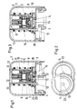
- a housing has 1 a hood 2 and a lower part 3.
- the housing 1 can with the help of a socket 4 on a valve housing be put on.
- the actuator 5 in the housing, whose expansion material 6, for example wax, by a Heating element 7 is heated.
- the actuator 5 consists of two parts, namely the first part 9 in the form of a Piston, which is the result of thermal expansion of the Expansion material can move outwards, and the second Part 8 in the form of an expansion material 6 and heating element 7 body.
- a first actuating pin 10 which is connected to the valve lifter of a normally closed valve can, is attached to the edge of a pot 11, the bottom 12 of which is arranged in an opening 13 of the housing 1 is.
- a second actuating pin 14 is on Bottom 15 of an inner pot 16 is provided. In the Free space between the floor 15 and the lower part 3 can a spacer 17 can be introduced.
- Version 4 is from the position illustrated in FIGS. 1 and 2, in which the socket axis with the first actuating pin 10 coincides, in the position illustrated in FIG. 3 movable, in the socket axis with the actuating pin 14 matches.
- the respective position of the Version 4 is indicated by the internal teeth 22 and external teeth 23 secured. It also illustrates that the opening 13 with a guide wall 27 is provided to safely guide the outer pot 11.
- the adjustment device for a normally closed NC valve is determined and the shape of the 1 and 2, the following function results:
- the second part 8 is supported of the actuator 5 with the interposition of the bottom 15 and the spacer 17 on the lower part 3 of the housing while the first part 9 of the actuator 5 moved outwards and against the outer pot 11 the force of the spring 18 and thus also the first actuating pin 10 takes away.
- the adjusting device is in operation.
- the amount of Spacer 17 you can adjust the rest position make the actuating pin 10.
- the adjustment device for a normally open NO valve it will be in the shape of the Fig. 3 brought. There are only two steps to this accomplish. First, version 4 with the second Actuating pin 14 brought into alignment. Secondly the spacer 17 through a side opening 24 removed. If heating is now carried out, it migrates the second actuating pin 14 towards the socket 4, because the first part 9 of the actuator 5 against the Bottom 12 of the outer pot 11 supports and this pot by the stronger spring 18 against the fixed stop 19 is held. The second part 8 of the actuator 5 therefore moves under compression of the weaker spring 20 in the direction of the to be adjusted Valve. If the actuating pin 14 hits an obstacle, especially when the operated valve closure piece when it reaches the seat, the outer one moves Pot 11 against the force of the spring 18 to the outside what again by stepping out of the bottom 12 from the Opening 13 can be seen.
Abstract
Description
Die Erfindung bezieht sich auf eine Vorrichtung zum umkehrbaren Verstellen eines Ventilstößels mit einem Gehäuse, einer Fassung zum Anschluß an ein Ventil, einem zwei gegeneinander verstellbare Teile aufweisenden thermischer Aktuator und zwei wahlweise zu verwendenden Betätigungsstiften, wobei für die eine Verstellart der erste Betätigungsstift von dem ersten Teil und für die andere Verstellart der zweite Betätigungsstift von dem zweiten Teil des Aktuators mitgenommen wird und der jeweils andere Teil des Aktuators am Gehäuse abgestützt ist.The invention relates to a device for reversible Adjusting a valve lifter with a housing, a socket for connection to a valve, a having two mutually adjustable parts thermal actuator and two optional ones Actuating pins, the one for the adjustment first actuating pin from the first part and for the another type of adjustment of the second actuating pin of the second part of the actuator is taken along and each other part of the actuator supported on the housing is.
Bei einer bekannten Vorrichtung dieser Art (DE-AS 16 00 713) ist wahlweise der eine oder der andere Betätigungsstift in der Achse des thermostatischen Aktuators einzubauen. Außerdem ist beim Wechsel von der einen zur anderen Betätigungsart nicht nur der Betätigungsstift, sondern auch ein Brückenelement auszuwechseln und eine Federanordnung zu ändern. Man kann daher die Verstellvorrichtung wahlweise für ein normalerweise offenes Ventil (NO) oder ein normalerweise geschlossenes Ventil (NC) verwenden, muß aber gegebenenfalls einen mühsamen Umbau vornehmen.In a known device of this type (DE-AS 16 00 713) is one or the other actuating pin in the axis of the thermostatic actuator to install. In addition, when changing from one for the other type of actuation not only the actuating pin, but also to replace a bridge element and change a spring arrangement. One can therefore the adjustment device optionally for a normally open valve (NO) or a normally closed one Use valve (NC), but may need one carry out tedious conversion.
Ferner ist eine Verstellvorrichtung bekannt (EP 0 856 692 A1), die für ein normalerweise geschlossenes Ventil bestimmt ist. Hier ist der Betätigungsstift ständig am Rand eines Topfes montiert, der den thermostatischen Aktuator übergreift und dessen Boden durch eine Feder kraftschlüssig an dem dem Betätigungsstift abgewandten Teil des Aktuators gehalten wird. Da der Betätigungsstift gegenüber der Aktuatorachse versetzt ist, kann der Hubweg des Betätigungsstiftes den Aktuator teilweise überlappen, so daß die Verstellvorrichtung eine geringe Höhe hat.An adjustment device is also known (EP 0 856 692 A1), which is for a normally closed Valve is determined. Here is the actuating pin constantly mounted on the edge of a pot, which the thermostatic Actuator overlaps and its bottom through a spring non-positively on the actuating pin part of the actuator facing away is held. Since the Actuating pin offset from the actuator axis the stroke of the actuating pin can be the actuator partially overlap so that the adjustment device has a low height.
Der Erfindung liegt die Aufgabe zugrunde, eine Vorrichtung der eingangs beschriebenen Art anzugeben, die eine erleichterte Umstellung von der einen Verstellart zur anderen Verstellart ermöglicht.The invention has for its object a device of the type described in the introduction, the one easier change from one adjustment to the other enables another type of adjustment.
Diese Aufgabe wird erfindungsgemäß dadurch gelöst, daß die beiden Betätigungsstifte ständig montiert, aber gegeneinander versetzt sind und daß die Betätigungsstifte und die Fassung relativ zueinander derart verlagerbar sind, daß die Fassung wahlweise mit dem ersten oder zweiten Betätigungsstift ausgerichtet ist.This object is achieved in that the two actuating pins are permanently installed, but against each other are offset and that the actuating pins and the frame can be displaced relative to one another in this way are that the version either with the first or second actuating pin is aligned.
Bei dieser Konstruktion erfordert ein Wechsel der Verstellart keinen Austausch der Betätigungsstifte. Vielmehr wird der benötigte Betätigungsstift durch eine relative Verlagerung zwischen den Betätigungsstiften und der Fassung wirksam gemacht. Da die Betätigungsstifte ständig montiert sind, können auch die Kraftübertragungswege zwischen Aktuator und Betätigungsstift weitgehend vorgegeben werden, so daß beim Wechsel der Verstellart zusätzlich zur Verlagerung der Fassung höchstens kleine Änderungen an der Verstellvorrichtung vorgenommen werden müssen.With this construction, a change of the adjustment type is required no replacement of the actuating pins. Much more is the required actuating pin by a relative Relocation between the actuating pins and the version made effective. Because the actuating pins are permanently installed, the power transmission paths largely between actuator and actuating pin be specified so that when changing the adjustment type in addition to relocating the version at most made small changes to the adjustment device Need to become.
Vorzugsweise sind die Betätigungsstifte zu beiden Seiten der Aktuatorachse angeordnet. Auf diese Weise erhalten die Betätigungsstifte den größtmöglichen Abstand voneinander, aber den kleinstmöglichen Abstand von der Achse des kraftgebenden Aktuators.The actuating pins are preferably on both sides arranged the actuator axis. Get this way the actuating pins the greatest possible distance from each other, but the smallest possible distance from the Axis of the power actuator.
Bei einer bevorzugten Ausführungsform ist dafür gesorgt, daß die Fassung und die Betätigungsstifte relativ zueinander geradlinig versetzbar sind. In a preferred embodiment, it is ensured that that the socket and the actuating pins are relative are linearly displaceable to each other.
Eine ebenfalls günstige Alternative besteht darin, daß die Fassung und die Betätigungsstifte relativ zueinander um eine Achse drehbar sind.Another cheap alternative is that the socket and the actuating pins relative to each other are rotatable about an axis.
Konstruktiv empfiehlt es sich, daß der Aktuator zwischen den Böden eines inneren und eines äußeren Topfes angeordnet ist und daß der äußere Topf den ersten Betätigungsstift und der innere Topf den zweiten Betätigungsstift trägt. Durch die Verwendung des inneren und äußeren Topfes ergibt sich bei geringem Platzaufwand eine gute Führung für die beiden Betätigungsstifte.It is structurally recommended that the actuator be between the bottoms of an inner and an outer pot is arranged and that the outer pot the first actuating pin and the inner pot the second actuating pin wearing. By using the inner and outer pot results in a small footprint a good guide for the two actuating pins.
Besonders günstig ist es, daß eine stärkere erste Feder den äußeren Topf gegen einen gehäusefesten Anschlag drückt, daß eine schwächere zweite Feder den inneren Topf gegen einen Anschlag am äußeren Topf drückt und daß zwischen dem Boden des inneren Topfes und einer gehäusefesten Abstützung ein Freiraum vorgesehen ist, in den zum Wechsel der Verstellart ein Distanzstück einschiebbar oder aus ihm herausnehmbar ist. Das Distanzstück ist das einzige Bauelement, das bei einem Wechsel der Verstellart außer der Verlagerung der Fassung gehandhabt werden muß. Der Wechsel ist daher sehr einfach zu vollziehen.It is particularly favorable that a stronger first spring the outer pot against a stop fixed to the housing presses a weaker second spring the inner one Press the pot against a stop on the outer pot and that between the bottom of the inner pot and a case fixed Support a free space is provided in a spacer can be inserted to change the type of adjustment or is removable from it. The spacer is the only component that comes with a change the type of adjustment except for the relocation of the version must become. The change is therefore very easy to accomplish.
Des weiteren empfiehlt es sich, daß das Gehäuse eine stirnseitige Öffnung hat, in der der Boden des äußeren Topfes angeordnet ist. Wenn der Boden aus der Öffnung heraustritt, ist dies bei normalerweise geschlossenem Ventil ein Zeichen für die Funktionsfähigkeit und bei normalerweise offenem Ventil ein Zeichen dafür, daß der Betätigungsstift eine Endlage erreicht hat.Furthermore, it is recommended that the housing be a has frontal opening in the bottom of the outer Pot is arranged. When the bottom comes out of the opening emerges, this is when the door is normally closed Valve a sign of functionality and at normally open valve indicates that the Actuating pin has reached an end position.
Vorzüge bietet es auch, daß die Außenseite des Bodens des äußeren Topfes eine Vertiefung für ein Werkzeug zum Verdrehen der Betätigungsstifte relativ zur Fassung aufweist. Ein einfaches Werkzeug, beispielsweise eine Münze, genügt, um die Fassung zu verlagern.It also has advantages that the outside of the floor the outer pot a recess for a tool for Twisting the actuating pins relative to the socket having. A simple tool, for example one Coin is enough to shift the frame.
Die Erfindung wird nachstehend anhand in der Zeichnung dargestellter bevorzugter Ausführungsbeispiele näher beschrieben. Hierin zeigen:
- Fig. 1
- einen Längsschnitt durch eine erfindungsgemäße Verstellvorrichtung in der NC-Verstellart,
- Fig. 2
- eine Ansicht von unten auf Fig. 1,
- Fig. 3
- einen Längsschnitt durch eine Verstellvorrichtung gemäß Fig. 1 in der NO-Verstellart,
- Fig. 4
- einen Längsschnitt durch eine abgewandelte Ausführungsform in der NC-Verstellart und
- Fig. 5
- einen Längsschnitt durch die Verstellvorrichtung der Fig. 4 in der NO-Verstellart.
- Fig. 1
- 2 shows a longitudinal section through an adjustment device according to the invention in the NC adjustment mode,
- Fig. 2
- a bottom view of Fig. 1,
- Fig. 3
- 2 shows a longitudinal section through an adjustment device according to FIG. 1 in the NO adjustment mode,
- Fig. 4
- a longitudinal section through a modified embodiment in the NC adjustment and
- Fig. 5
- a longitudinal section through the adjustment device of FIG. 4 in the NO adjustment mode.
Bei der Ausführungsform der Fig. 1 bis 3 weist ein Gehäuse
1 eine Haube 2 und ein Unterteil 3 auf. Das Gehäuse
1 kann mit Hilfe einer Fassung 4 auf ein Ventilgehäuse
aufgesetzt werden.In the embodiment of FIGS. 1 to 3, a housing has
1 a
Im Gehäuse befindet sich ein thermischer Aktuator 5,
dessen Dehnstoff 6, beispielsweise Wachs, durch ein
Heizelement 7 beheizbar ist. Der Aktuator 5 besteht aus
zwei Teilen, nämlich dem ersten Teil 9 in der Form eines
Kolbens, der sich in Folge Wärmeausdehnung des
Dehnstoffes nach außen verschieben läßt, und dem zweiten
Teil 8 in der Form eines Dehnstoff 6 und Heizelement
7 aufweisenden Korpus. There is a
Ein erster Betätigungsstift 10, der mit dem Ventilstößel
eines normalerweise geschlossenen Ventils zusammenwirken
kann, ist am Rande eines Topfes 11 angebracht,
dessen Boden 12 in einer Öffnung 13 des Gehäuses 1 angeordnet
ist. Ein zweiter Betätigungsstift 14 ist am
Boden 15 eines inneren Topfes 16 vorgesehen. In den
Freiraum zwischen dem Boden 15 und dem Unterteil 3 kann
ein Distanzstück 17 eingebracht werden.A first actuating
Eine stärkere Feder 18 drückt den äußeren Topf 11 gegen
einen gehäusefesten Anschlag 19 am Unterteil 3. Eine
schwächere Feder 20 drückt den inneren Topf 16 gegen
einen Anschlag 21 am äußeren Topf. Die Fassung 4 ist
aus der in Fig. 1 und 2 veranschaulichten Stellung, in
der die Fassungsachse mit dem ersten Betätigungsstift
10 übereinstimmt, in die in Fig. 3 veranschaulichte Lage
versetzbar, in der die Fassungsachse mit dem Betätigungsstift
14 übereinstimmt. Die jeweilige Stellung der
Fassung 4 wird durch die angedeutete Innenverzahnung 22
und Außenverzahnung 23 gesichert. Außerdem ist veranschaulicht,
daß die Öffnung 13 mit einer Führungswand
27 versehen ist, um den äußeren Topf 11 sicher zu führen.A
Wenn die Verstellvorrichtung für ein normalerweise geschlossenes
NC-Ventil bestimmt ist und die Form der
Fig. 1 und 2 besitzt, ergibt sich die folgende Funktion:
Bei einer Beheizung stützt sich der zweite Teil 8
des Aktuators 5 unter Zwischenschaltung des Bodens 15
und des Distanzstückes 17 auf dem Unterteil 3 des Gehäuses
ab, während sich der erste Teil 9 des Aktuators
5 nach außen bewegt und dabei den äußeren Topf 11 gegen
die Kraft der Feder 18 und damit auch den ersten Betätigungsstift
10 mitnimmt. Durch Heraustreten des Bodens
12 aus der Öffnung 13 ist erkennbar, daß die Verstellvorrichtung
in Betrieb ist. Durch Wahl der Höhe des
Distanzstückes 17 kann man eine Anpassung der Ruhelage
des Betätigungsstiftes 10 vornehmen.If the adjustment device for a normally closed
NC valve is determined and the shape of the
1 and 2, the following function results:
In the case of heating, the
Wenn die Verstellvorrichtung für ein normalerweise offenes
NO-Ventil bestimmt ist, wird es in die Form der
Fig. 3 gebracht. Hierzu sind lediglich zwei Schritte zu
vollführen. Erstens wird die Fassung 4 mit dem zweiten
Betätigungsstift 14 in Ausrichtung gebracht. Zweitens
wird das Distanzstück 17 durch eine seitliche Öffnung
24 entfernt. Wenn nunmehr eine Beheizung erfolgt, wandert
der zweite Betätigungsstift 14 zur Fassung 4 hin,
weil sich der erste Teil 9 des Aktuators 5 gegen den
Boden 12 des äußeren Topfes 11 abstützt und dieser Topf
durch die stärkere Feder 18 gegen den gehäusefesten Anschlag
19 gehalten wird. Der zweite Teil 8 des Aktuators
5 bewegt sich daher unter Zusammenpressung der
schwächeren Feder 20 in Richtung auf das zu verstellende
Ventil. Stößt der Betätigungsstift 14 gegen ein Hindernis,
insbesondere, wenn das betätigte Ventilverschlußstück
den Sitz erreicht, wandert der äußere
Topf 11 gegen die Kraft der Feder 18 nach außen, was
wiederum durch das Heraustreten des Bodens 12 aus der
Öffnung 13 erkennbar ist.If the adjustment device for a normally open
NO valve is determined, it will be in the shape of the
Fig. 3 brought. There are only two steps to this
accomplish. First,
Bei den Fig. 4 und 5 werden für entsprechende Teile um
100 erhöhte Bezugszeichen gegenüber den Fig. 1 bis 3
verwendet. Die Verstellung der beiden Betätigungsstifte
110 und 114 durch den thermostatischen Aktuator 105 ist
identisch mit dem vorangegangenen Beispiel. Unterschiedlich
ist im wesentlichen, daß das Gehäuse 101 eine
Grundplatte 125 mit kreisförmigem Querschnitt aufweist,
die einstückig mit einer exzentrisch angeordneten
Fassung 104 verbunden ist. Durch eine Relativdrehung
zwischen dem Unterteil 103 und der Grundplatte 125
kann man die Fassung 104 wahlweise mit dem ersten Betätigungsstift
110 (Fig. 4) oder dem zweiten Betätigungsgstift
114 (Fig. 5) in Ausrichtung bringen. Um
diese Drehung zu bewerkstelligen, ist im Boden 112 des
äußeren Topfes 111 eine Vertiefung 126 vorgesehen, in
die ein Werkzeug, wie eine Münze, eingesetzt werden
kann.4 and 5 are for corresponding parts
100 increased reference numerals compared to FIGS. 1 to 3
used. The adjustment of the two actuating
Claims (8)
Applications Claiming Priority (2)
| Application Number | Priority Date | Filing Date | Title |
|---|---|---|---|
| DE19901283A DE19901283C2 (en) | 1999-01-15 | 1999-01-15 | Device for the reversible adjustment of a valve tappet |
| DE19901283 | 1999-01-15 |
Publications (3)
| Publication Number | Publication Date |
|---|---|
| EP1020782A2 true EP1020782A2 (en) | 2000-07-19 |
| EP1020782A3 EP1020782A3 (en) | 2001-11-21 |
| EP1020782B1 EP1020782B1 (en) | 2004-10-13 |
Family
ID=7894302
Family Applications (1)
| Application Number | Title | Priority Date | Filing Date |
|---|---|---|---|
| EP99204420A Expired - Lifetime EP1020782B1 (en) | 1999-01-15 | 1999-12-20 | Device for reversibly positioning a valve stem |
Country Status (4)
| Country | Link |
|---|---|
| EP (1) | EP1020782B1 (en) |
| AT (1) | ATE279747T1 (en) |
| DE (1) | DE19901283C2 (en) |
| ES (1) | ES2230799T3 (en) |
Cited By (2)
| Publication number | Priority date | Publication date | Assignee | Title |
|---|---|---|---|---|
| EP1808625A3 (en) * | 2006-01-11 | 2007-09-26 | Honeywell Technologies Sarl | Actuating device for a valve |
| US7617989B2 (en) | 2005-04-26 | 2009-11-17 | Caleffi S.P.A. | Automatically reclosable thermostatic control device for valves |
Families Citing this family (4)
| Publication number | Priority date | Publication date | Assignee | Title |
|---|---|---|---|---|
| DE19916535C2 (en) * | 1999-04-13 | 2002-06-27 | Danfoss As | Device for the reversible adjustment of a valve tappet |
| DE10106257B4 (en) * | 2001-02-10 | 2004-05-27 | Andreas Möhlenhoff | Device for operating a valve |
| DE10158602C2 (en) * | 2001-11-29 | 2003-11-20 | Heimeier Gmbh Metall Theodor | Remotely adjustable cooling valve |
| US9391430B2 (en) | 2013-01-25 | 2016-07-12 | Ford Global Technologies, Llc | Ignition plug and method for the ignition of a fuel-air mixture by means of an ignition plug of said type |
Citations (2)
| Publication number | Priority date | Publication date | Assignee | Title |
|---|---|---|---|---|
| DE1600713A1 (en) | 1967-05-13 | 1970-01-15 | Behr Thomson Dehnstoffregler | Zone valve with adjustment device |
| EP0856692A1 (en) | 1997-01-30 | 1998-08-05 | Andreas Möhlenhoff | Valve stem positioning device |
Family Cites Families (2)
| Publication number | Priority date | Publication date | Assignee | Title |
|---|---|---|---|---|
| DE2951983A1 (en) * | 1979-12-22 | 1981-07-23 | Calor-Emag Elektrizitäts-Aktiengesellschaft, 4030 Ratingen | Rapid action breaker for short-circuit currents - uses explosion of first breaker point to position contact pin latch for second breaker point |
| FR2751057A1 (en) * | 1996-07-12 | 1998-01-16 | Guedes Yvon | Winter/summer switching appts. for thermostatic taps in radiator central heating system |
-
1999
- 1999-01-15 DE DE19901283A patent/DE19901283C2/en not_active Expired - Fee Related
- 1999-12-20 AT AT99204420T patent/ATE279747T1/en not_active IP Right Cessation
- 1999-12-20 ES ES99204420T patent/ES2230799T3/en not_active Expired - Lifetime
- 1999-12-20 EP EP99204420A patent/EP1020782B1/en not_active Expired - Lifetime
Patent Citations (2)
| Publication number | Priority date | Publication date | Assignee | Title |
|---|---|---|---|---|
| DE1600713A1 (en) | 1967-05-13 | 1970-01-15 | Behr Thomson Dehnstoffregler | Zone valve with adjustment device |
| EP0856692A1 (en) | 1997-01-30 | 1998-08-05 | Andreas Möhlenhoff | Valve stem positioning device |
Cited By (2)
| Publication number | Priority date | Publication date | Assignee | Title |
|---|---|---|---|---|
| US7617989B2 (en) | 2005-04-26 | 2009-11-17 | Caleffi S.P.A. | Automatically reclosable thermostatic control device for valves |
| EP1808625A3 (en) * | 2006-01-11 | 2007-09-26 | Honeywell Technologies Sarl | Actuating device for a valve |
Also Published As
| Publication number | Publication date |
|---|---|
| ATE279747T1 (en) | 2004-10-15 |
| EP1020782A3 (en) | 2001-11-21 |
| ES2230799T3 (en) | 2005-05-01 |
| DE19901283A1 (en) | 2000-08-03 |
| EP1020782B1 (en) | 2004-10-13 |
| DE19901283C2 (en) | 2001-05-03 |
Similar Documents
| Publication | Publication Date | Title |
|---|---|---|
| EP1707723B1 (en) | Damping device for displaceable furniture parts | |
| EP1727954B1 (en) | Hinge, in particular for connecting two door elements of a folding door | |
| DE3300624C2 (en) | Valve with presetting of the flow rate | |
| DE102004020655A1 (en) | Locking unit for a movable locking element | |
| EP1020782B1 (en) | Device for reversibly positioning a valve stem | |
| DE2620558C3 (en) | Valve | |
| DE2746725C2 (en) | Knitting machine lock | |
| EP2251578B1 (en) | Rotary handle for a sanitary fitting | |
| EP0768690A1 (en) | Pivotable actuator for a safety switch | |
| WO2020236099A1 (en) | Furniture fitting | |
| DE4240218C2 (en) | Switching device | |
| WO2000061974A1 (en) | Device for reversibly adjusting a valve tappet | |
| DE10030699C2 (en) | Preset cartridge valve | |
| EP0856692A1 (en) | Valve stem positioning device | |
| DE10308613A1 (en) | Valve with a lever, lever and method for producing a lever | |
| EP3215772B1 (en) | Valve device | |
| EP0263811B1 (en) | Single lever sanitary mixing battery | |
| DE10106257B4 (en) | Device for operating a valve | |
| DE2516070B2 (en) | ELECTRIC SWITCH | |
| DE19609987C2 (en) | Control device for a multi-way valve | |
| EP1102144A2 (en) | Valve, in particular a thermostatic valve for heating systems | |
| DE3836683C1 (en) | Compass with adjustment spindle, especially rapid-adjustment compass | |
| DE202007012004U1 (en) | Transmission element and adjustment fitting | |
| AT9711U1 (en) | FURNITURE FITTING, PARTICULAR FURNITURE HARNESS | |
| DE2726608B1 (en) | Pressure dependent electrical switching device |
Legal Events
| Date | Code | Title | Description |
|---|---|---|---|
| PUAI | Public reference made under article 153(3) epc to a published international application that has entered the european phase |
Free format text: ORIGINAL CODE: 0009012 |
|
| AK | Designated contracting states |
Kind code of ref document: A2 Designated state(s): AT BE CH CY DE DK ES FI FR GB GR IE IT LI LU MC NL PT SE |
|
| AX | Request for extension of the european patent |
Free format text: AL;LT;LV;MK;RO;SI |
|
| PUAL | Search report despatched |
Free format text: ORIGINAL CODE: 0009013 |
|
| AK | Designated contracting states |
Kind code of ref document: A3 Designated state(s): AT BE CH CY DE DK ES FI FR GB GR IE IT LI LU MC NL PT SE |
|
| AX | Request for extension of the european patent |
Free format text: AL;LT;LV;MK;RO;SI |
|
| AKX | Designation fees paid |
Free format text: AT BE CH CY DE DK ES FI FR GB GR IE IT LI LU MC NL PT SE |
|
| 17P | Request for examination filed |
Effective date: 20011212 |
|
| GRAP | Despatch of communication of intention to grant a patent |
Free format text: ORIGINAL CODE: EPIDOSNIGR1 |
|
| GRAS | Grant fee paid |
Free format text: ORIGINAL CODE: EPIDOSNIGR3 |
|
| RBV | Designated contracting states (corrected) |
Designated state(s): AT BE CH CY DK ES FI FR GB GR IE IT LI LU MC NL PT SE |
|
| REG | Reference to a national code |
Ref country code: DE Ref legal event code: 8566 |
|
| GRAA | (expected) grant |
Free format text: ORIGINAL CODE: 0009210 |
|
| AK | Designated contracting states |
Kind code of ref document: B1 Designated state(s): AT BE CH CY DK ES FI FR GB GR IE IT LI LU MC NL PT SE |
|
| PG25 | Lapsed in a contracting state [announced via postgrant information from national office to epo] |
Ref country code: NL Free format text: LAPSE BECAUSE OF FAILURE TO SUBMIT A TRANSLATION OF THE DESCRIPTION OR TO PAY THE FEE WITHIN THE PRESCRIBED TIME-LIMIT Effective date: 20041013 Ref country code: FI Free format text: LAPSE BECAUSE OF FAILURE TO SUBMIT A TRANSLATION OF THE DESCRIPTION OR TO PAY THE FEE WITHIN THE PRESCRIBED TIME-LIMIT Effective date: 20041013 Ref country code: CY Free format text: LAPSE BECAUSE OF FAILURE TO SUBMIT A TRANSLATION OF THE DESCRIPTION OR TO PAY THE FEE WITHIN THE PRESCRIBED TIME-LIMIT Effective date: 20041013 |
|
| REG | Reference to a national code |
Ref country code: GB Ref legal event code: FG4D Free format text: NOT ENGLISH |
|
| REG | Reference to a national code |
Ref country code: CH Ref legal event code: EP |
|
| REG | Reference to a national code |
Ref country code: IE Ref legal event code: FG4D Free format text: GERMAN |
|
| PG25 | Lapsed in a contracting state [announced via postgrant information from national office to epo] |
Ref country code: LU Free format text: LAPSE BECAUSE OF NON-PAYMENT OF DUE FEES Effective date: 20041220 |
|
| PG25 | Lapsed in a contracting state [announced via postgrant information from national office to epo] |
Ref country code: MC Free format text: LAPSE BECAUSE OF NON-PAYMENT OF DUE FEES Effective date: 20041231 Ref country code: BE Free format text: LAPSE BECAUSE OF NON-PAYMENT OF DUE FEES Effective date: 20041231 |
|
| PG25 | Lapsed in a contracting state [announced via postgrant information from national office to epo] |
Ref country code: GR Free format text: LAPSE BECAUSE OF FAILURE TO SUBMIT A TRANSLATION OF THE DESCRIPTION OR TO PAY THE FEE WITHIN THE PRESCRIBED TIME-LIMIT Effective date: 20050113 Ref country code: DK Free format text: LAPSE BECAUSE OF FAILURE TO SUBMIT A TRANSLATION OF THE DESCRIPTION OR TO PAY THE FEE WITHIN THE PRESCRIBED TIME-LIMIT Effective date: 20050113 |
|
| REG | Reference to a national code |
Ref country code: CH Ref legal event code: NV Representative=s name: LUCHS & PARTNER PATENTANWAELTE |
|
| REG | Reference to a national code |
Ref country code: SE Ref legal event code: TRGR |
|
| GBT | Gb: translation of ep patent filed (gb section 77(6)(a)/1977) |
Effective date: 20050116 |
|
| NLV1 | Nl: lapsed or annulled due to failure to fulfill the requirements of art. 29p and 29m of the patents act | ||
| REG | Reference to a national code |
Ref country code: ES Ref legal event code: FG2A Ref document number: 2230799 Country of ref document: ES Kind code of ref document: T3 |
|
| BERE | Be: lapsed |
Owner name: DANFOSS A/S Effective date: 20041231 |
|
| PLBE | No opposition filed within time limit |
Free format text: ORIGINAL CODE: 0009261 |
|
| STAA | Information on the status of an ep patent application or granted ep patent |
Free format text: STATUS: NO OPPOSITION FILED WITHIN TIME LIMIT |
|
| ET | Fr: translation filed | ||
| 26N | No opposition filed |
Effective date: 20050714 |
|
| PGFP | Annual fee paid to national office [announced via postgrant information from national office to epo] |
Ref country code: SE Payment date: 20061206 Year of fee payment: 8 |
|
| PGFP | Annual fee paid to national office [announced via postgrant information from national office to epo] |
Ref country code: IE Payment date: 20061213 Year of fee payment: 8 Ref country code: AT Payment date: 20061213 Year of fee payment: 8 |
|
| PGFP | Annual fee paid to national office [announced via postgrant information from national office to epo] |
Ref country code: ES Payment date: 20070122 Year of fee payment: 8 |
|
| BERE | Be: lapsed |
Owner name: *DANFOSS A/S Effective date: 20041231 |
|
| PG25 | Lapsed in a contracting state [announced via postgrant information from national office to epo] |
Ref country code: PT Free format text: LAPSE BECAUSE OF NON-PAYMENT OF DUE FEES Effective date: 20050313 |
|
| PGFP | Annual fee paid to national office [announced via postgrant information from national office to epo] |
Ref country code: CH Payment date: 20071213 Year of fee payment: 9 Ref country code: IT Payment date: 20071220 Year of fee payment: 9 |
|
| PGFP | Annual fee paid to national office [announced via postgrant information from national office to epo] |
Ref country code: GB Payment date: 20071219 Year of fee payment: 9 Ref country code: FR Payment date: 20071210 Year of fee payment: 9 |
|
| EUG | Se: european patent has lapsed | ||
| PG25 | Lapsed in a contracting state [announced via postgrant information from national office to epo] |
Ref country code: AT Free format text: LAPSE BECAUSE OF NON-PAYMENT OF DUE FEES Effective date: 20071220 |
|
| REG | Reference to a national code |
Ref country code: IE Ref legal event code: MM4A |
|
| PG25 | Lapsed in a contracting state [announced via postgrant information from national office to epo] |
Ref country code: SE Free format text: LAPSE BECAUSE OF NON-PAYMENT OF DUE FEES Effective date: 20071221 Ref country code: IE Free format text: LAPSE BECAUSE OF NON-PAYMENT OF DUE FEES Effective date: 20071220 |
|
| REG | Reference to a national code |
Ref country code: ES Ref legal event code: FD2A Effective date: 20071221 |
|
| PG25 | Lapsed in a contracting state [announced via postgrant information from national office to epo] |
Ref country code: ES Free format text: LAPSE BECAUSE OF NON-PAYMENT OF DUE FEES Effective date: 20071221 |
|
| REG | Reference to a national code |
Ref country code: CH Ref legal event code: PL |
|
| GBPC | Gb: european patent ceased through non-payment of renewal fee |
Effective date: 20081220 |
|
| REG | Reference to a national code |
Ref country code: FR Ref legal event code: ST Effective date: 20090831 |
|
| PG25 | Lapsed in a contracting state [announced via postgrant information from national office to epo] |
Ref country code: LI Free format text: LAPSE BECAUSE OF NON-PAYMENT OF DUE FEES Effective date: 20081231 Ref country code: CH Free format text: LAPSE BECAUSE OF NON-PAYMENT OF DUE FEES Effective date: 20081231 |
|
| PG25 | Lapsed in a contracting state [announced via postgrant information from national office to epo] |
Ref country code: GB Free format text: LAPSE BECAUSE OF NON-PAYMENT OF DUE FEES Effective date: 20081220 |
|
| PG25 | Lapsed in a contracting state [announced via postgrant information from national office to epo] |
Ref country code: FR Free format text: LAPSE BECAUSE OF NON-PAYMENT OF DUE FEES Effective date: 20081231 |
|
| PG25 | Lapsed in a contracting state [announced via postgrant information from national office to epo] |
Ref country code: IT Free format text: LAPSE BECAUSE OF NON-PAYMENT OF DUE FEES Effective date: 20081220 |