EP1020329A1 - Support orientable motorisé pour afficheur multifonctions dans un véhicule - Google Patents
Support orientable motorisé pour afficheur multifonctions dans un véhicule Download PDFInfo
- Publication number
- EP1020329A1 EP1020329A1 EP00400043A EP00400043A EP1020329A1 EP 1020329 A1 EP1020329 A1 EP 1020329A1 EP 00400043 A EP00400043 A EP 00400043A EP 00400043 A EP00400043 A EP 00400043A EP 1020329 A1 EP1020329 A1 EP 1020329A1
- Authority
- EP
- European Patent Office
- Prior art keywords
- vehicle
- display
- seat
- remote control
- motorization
- Prior art date
- Legal status (The legal status is an assumption and is not a legal conclusion. Google has not performed a legal analysis and makes no representation as to the accuracy of the status listed.)
- Granted
Links
- 230000010365 information processing Effects 0.000 description 3
- 238000010586 diagram Methods 0.000 description 1
- 238000002513 implantation Methods 0.000 description 1
- 230000005855 radiation Effects 0.000 description 1
Images
Classifications
-
- B—PERFORMING OPERATIONS; TRANSPORTING
- B60—VEHICLES IN GENERAL
- B60R—VEHICLES, VEHICLE FITTINGS, OR VEHICLE PARTS, NOT OTHERWISE PROVIDED FOR
- B60R11/00—Arrangements for holding or mounting articles, not otherwise provided for
- B60R11/02—Arrangements for holding or mounting articles, not otherwise provided for for radio sets, television sets, telephones, or the like; Arrangement of controls thereof
- B60R11/0229—Arrangements for holding or mounting articles, not otherwise provided for for radio sets, television sets, telephones, or the like; Arrangement of controls thereof for displays, e.g. cathodic tubes
- B60R11/0235—Arrangements for holding or mounting articles, not otherwise provided for for radio sets, television sets, telephones, or the like; Arrangement of controls thereof for displays, e.g. cathodic tubes of flat type, e.g. LCD
-
- B—PERFORMING OPERATIONS; TRANSPORTING
- B60—VEHICLES IN GENERAL
- B60R—VEHICLES, VEHICLE FITTINGS, OR VEHICLE PARTS, NOT OTHERWISE PROVIDED FOR
- B60R11/00—Arrangements for holding or mounting articles, not otherwise provided for
- B60R2011/0001—Arrangements for holding or mounting articles, not otherwise provided for characterised by position
- B60R2011/0003—Arrangements for holding or mounting articles, not otherwise provided for characterised by position inside the vehicle
- B60R2011/0005—Dashboard
-
- B—PERFORMING OPERATIONS; TRANSPORTING
- B60—VEHICLES IN GENERAL
- B60R—VEHICLES, VEHICLE FITTINGS, OR VEHICLE PARTS, NOT OTHERWISE PROVIDED FOR
- B60R11/00—Arrangements for holding or mounting articles, not otherwise provided for
- B60R2011/0042—Arrangements for holding or mounting articles, not otherwise provided for characterised by mounting means
- B60R2011/0043—Arrangements for holding or mounting articles, not otherwise provided for characterised by mounting means for integrated articles, i.e. not substantially protruding from the surrounding parts
- B60R2011/0045—Arrangements for holding or mounting articles, not otherwise provided for characterised by mounting means for integrated articles, i.e. not substantially protruding from the surrounding parts with visible part, e.g. flush mounted
-
- B—PERFORMING OPERATIONS; TRANSPORTING
- B60—VEHICLES IN GENERAL
- B60R—VEHICLES, VEHICLE FITTINGS, OR VEHICLE PARTS, NOT OTHERWISE PROVIDED FOR
- B60R11/00—Arrangements for holding or mounting articles, not otherwise provided for
- B60R2011/0042—Arrangements for holding or mounting articles, not otherwise provided for characterised by mounting means
- B60R2011/008—Adjustable or movable supports
- B60R2011/0085—Adjustable or movable supports with adjustment by rotation in their operational position
-
- B—PERFORMING OPERATIONS; TRANSPORTING
- B60—VEHICLES IN GENERAL
- B60R—VEHICLES, VEHICLE FITTINGS, OR VEHICLE PARTS, NOT OTHERWISE PROVIDED FOR
- B60R11/00—Arrangements for holding or mounting articles, not otherwise provided for
- B60R2011/0042—Arrangements for holding or mounting articles, not otherwise provided for characterised by mounting means
- B60R2011/008—Adjustable or movable supports
- B60R2011/0092—Adjustable or movable supports with motorization
-
- B—PERFORMING OPERATIONS; TRANSPORTING
- B60—VEHICLES IN GENERAL
- B60R—VEHICLES, VEHICLE FITTINGS, OR VEHICLE PARTS, NOT OTHERWISE PROVIDED FOR
- B60R11/00—Arrangements for holding or mounting articles, not otherwise provided for
- B60R11/02—Arrangements for holding or mounting articles, not otherwise provided for for radio sets, television sets, telephones, or the like; Arrangement of controls thereof
- B60R2011/0282—Arrangements for holding or mounting articles, not otherwise provided for for radio sets, television sets, telephones, or the like; Arrangement of controls thereof for the use of several passengers, e.g. simultaneously
Definitions
- the present invention relates to a system for fixing a display. multifunction including navigation aid in a motor vehicle.
- These displays are for example installed in or on the board on board the vehicle.
- the object of the invention is therefore to solve these problems.
- the invention relates to a system for fixing a display.
- multifunction including navigation aid in a motor vehicle, characterized in that the display is fixed to the rest of the structure of the vehicle by means of support orientable towards the driver's seat or front passenger seat of the vehicle, via motorization means whose operation is controlled by control means.
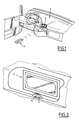
- FIG. 1 shows a part of the vehicle interior automotive and more particularly a dashboard designated by the general reference 1, of it.
- a multifunction display designated for example by the general reference 2 can be installed in this dashboard, and more particularly in the central portion of it.
- This multifunction display is for example associated with a system aid to navigation of the motor vehicle and is then adapted to display guidance information for this vehicle.
- this display multifunction 2 can for example be remotely controllable via a remote control unit such as that designated by the reference general 3 in FIG. 1, using for example infrared radiation for allow a user to control the operation of this display and the system.
- a remote control unit such as that designated by the reference general 3 in FIG. 1, using for example infrared radiation for allow a user to control the operation of this display and the system.
- the order information is then transmitted from the box remote control 3 towards display 2 via for example of an information transmitter.
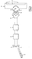
- the multifunction display can then be associated, as can be see in Figure 2, two corresponding receivers designated by the references general 4 and 5 in this figure, and directed one, for example 4, towards the seat driver and the other, for example 5, to the passenger seat front of the vehicle.
- receivers 4 and 5 are connected to an information processing unit designated by the general reference 6 on this figure, which is itself connected at the output to a power interface designated by the general reference 7, to control the operation of means 8 for motorizing the movements of support means 9 of the display multifunction 2 compared to the rest of the vehicle structure.
- the motorization means 8 comprise for example a motor electric whose output shaft is associated with a portion-shaped member of pinion 10 adapted to cooperate with a member in the form of a pinion portion 11 associated with the support means 9 of this multifunction display 2.
- These support means are then pivotally mounted relative to the rest of the vehicle structure, for example around an axis materialized by the reference 12 in this figure.
- the information processing unit 6 analyzes the output of receptors 4 and 5 described above, to determine which of these receptors receives information from the remote control.
- this information processing unit 6 controls the power interface 7 to control the power supply to the electric motor 8 in one direction or the other in order to move the multifunction display in either of these directions.
Landscapes
- Engineering & Computer Science (AREA)
- Mechanical Engineering (AREA)
- Fittings On The Vehicle Exterior For Carrying Loads, And Devices For Holding Or Mounting Articles (AREA)
- Devices For Indicating Variable Information By Combining Individual Elements (AREA)
- Instrument Panels (AREA)
- Lighting Device Outwards From Vehicle And Optical Signal (AREA)
- Switches With Compound Operations (AREA)
- Control Of Position, Course, Altitude, Or Attitude Of Moving Bodies (AREA)
- Navigation (AREA)
- Electric Propulsion And Braking For Vehicles (AREA)
Abstract
Description
- la Fig.1 illustre l'implantation d'un afficheur multifonctions dans une planche de bord de véhicule automobile;
- la Fig.2 représente une vue à échelle agrandie de cet afficheur; et
- la Fig.3 représente un schéma synoptique illustrant la structure générale de moyens de commande de l'orientation de cet afficheur, entrant dans la constitution d'un système selon l'invention.
Claims (5)
- Système de fixation d'un afficheur multifonctions (2) notamment d'aide à la navigation, dans un véhicule automobile, caractérisé en ce que l'afficheur (2) est fixé sur le reste de la structure du véhicule par l'intermédiaire de moyens de support (9) orientables en direction du siège du conducteur et du siège du passager avant du véhicule, par l'intermédiaire de moyens de motorisation (8) dont le fonctionnement est piloté par des moyens de commande (3,4,5,6,7).
- Système selon la revendication 1, caractérisé en ce que les moyens de commande comprennent des moyens de commande à distance (3,4,5) du système de navigation.
- Système selon la revendication 2, caractérisé en ce que les moyens de commande à distance comprennent un émetteur d'informations (3) à disposition de l'utilisateur et deux récepteurs correspondants (4,5) associés à l'afficheur (2) et dirigés l'un vers le siège de conducteur du véhicule et l'autre, vers le siège de passager avant de celui-ci et dont la sortie est reliée à l'unité de traitement d'informations (6) pour détecter le récepteur (4,5) recevant les informations en provenance des moyens de commande à distance pour orienter l'afficheur (2) dans la direction correspondante.
- Système selon l'une quelconque des revendications précédentes, caractérisé en ce que les moyens de support (9) sont montés pivotants (en 12) par rapport au reste de la structure du véhicule et sont associés à un organe (11) en forme de portion de pignon adapté pour coopérer avec un organe (10) en forme de portion de pignon associé aux moyens de motorisation (8).
- Système selon l'une quelconque des revendications précédentes, caractérisé en ce que les moyens de motorisation (8) comprennent un moteur électrique.
Applications Claiming Priority (2)
| Application Number | Priority Date | Filing Date | Title |
|---|---|---|---|
| FR9900238 | 1999-01-12 | ||
| FR9900238A FR2788244B1 (fr) | 1999-01-12 | 1999-01-12 | Systeme de fixation d'un afficheur multifonctions notamment d'aide a la navigation, dans un vehicule automobile |
Publications (2)
| Publication Number | Publication Date |
|---|---|
| EP1020329A1 true EP1020329A1 (fr) | 2000-07-19 |
| EP1020329B1 EP1020329B1 (fr) | 2003-10-01 |
Family
ID=9540786
Family Applications (1)
| Application Number | Title | Priority Date | Filing Date |
|---|---|---|---|
| EP00400043A Expired - Lifetime EP1020329B1 (fr) | 1999-01-12 | 2000-01-10 | Support orientable motorisé pour afficheur multifonctions dans un véhicule |
Country Status (4)
| Country | Link |
|---|---|
| EP (1) | EP1020329B1 (fr) |
| AT (1) | ATE251054T1 (fr) |
| DE (1) | DE60005569T2 (fr) |
| FR (1) | FR2788244B1 (fr) |
Cited By (6)
| Publication number | Priority date | Publication date | Assignee | Title |
|---|---|---|---|---|
| FR2828855A1 (fr) * | 2001-08-24 | 2003-02-28 | Renault | Ecran multimedia integre dans un vehicule |
| EP1283132A3 (fr) * | 2001-08-06 | 2003-12-03 | Pioneer Corporation | Appareil électronique, mécanisme d'entraínement et sa méthode de commande pour la façade |
| EP1323586A3 (fr) * | 2001-12-28 | 2004-03-17 | Pioneer Corporation | Commande d'entraínement et méthode de commande |
| EP1491406A1 (fr) * | 2003-06-16 | 2004-12-29 | Matsushita Electric Industrial Co., Ltd. | Appareil embarqué de contrôle à distance pour véhicule et procédé |
| EP1768082A4 (fr) * | 2004-06-30 | 2009-06-24 | Clarion Co Ltd | Appareil d'entraînement de panneaux |
| CN108583456A (zh) * | 2018-04-19 | 2018-09-28 | 深圳市晓控通信科技有限公司 | 一种具有防尘及角度调节功能的汽车智慧导航 |
Citations (6)
| Publication number | Priority date | Publication date | Assignee | Title |
|---|---|---|---|---|
| EP0341182A2 (fr) * | 1988-05-04 | 1989-11-08 | Alberto Gonzalez Miruri | Dispositif de sécurité pour cacher un appareil |
| JPH04224432A (ja) * | 1990-12-26 | 1992-08-13 | Toshiba Corp | 車載テレビジョン装置 |
| DE4213129A1 (de) * | 1992-04-21 | 1993-10-28 | Audi Ag | Fahrerinformationssystem mit einem Bildschirm in einem Kraftfahrzeug |
| JPH08110758A (ja) * | 1995-07-05 | 1996-04-30 | Alpine Electron Inc | ディスプレイ装置 |
| JPH09109791A (ja) * | 1995-10-23 | 1997-04-28 | Daifuretsukusu:Kk | センサー搭載車載用モニター支持具 |
| WO1998009842A1 (fr) * | 1996-09-03 | 1998-03-12 | Ut Automotive Dearborn, Inc. | Dispositif d'affichage a deux ecrans |
-
1999
- 1999-01-12 FR FR9900238A patent/FR2788244B1/fr not_active Expired - Lifetime
-
2000
- 2000-01-10 AT AT00400043T patent/ATE251054T1/de not_active IP Right Cessation
- 2000-01-10 EP EP00400043A patent/EP1020329B1/fr not_active Expired - Lifetime
- 2000-01-10 DE DE60005569T patent/DE60005569T2/de not_active Expired - Lifetime
Patent Citations (6)
| Publication number | Priority date | Publication date | Assignee | Title |
|---|---|---|---|---|
| EP0341182A2 (fr) * | 1988-05-04 | 1989-11-08 | Alberto Gonzalez Miruri | Dispositif de sécurité pour cacher un appareil |
| JPH04224432A (ja) * | 1990-12-26 | 1992-08-13 | Toshiba Corp | 車載テレビジョン装置 |
| DE4213129A1 (de) * | 1992-04-21 | 1993-10-28 | Audi Ag | Fahrerinformationssystem mit einem Bildschirm in einem Kraftfahrzeug |
| JPH08110758A (ja) * | 1995-07-05 | 1996-04-30 | Alpine Electron Inc | ディスプレイ装置 |
| JPH09109791A (ja) * | 1995-10-23 | 1997-04-28 | Daifuretsukusu:Kk | センサー搭載車載用モニター支持具 |
| WO1998009842A1 (fr) * | 1996-09-03 | 1998-03-12 | Ut Automotive Dearborn, Inc. | Dispositif d'affichage a deux ecrans |
Non-Patent Citations (3)
| Title |
|---|
| PATENT ABSTRACTS OF JAPAN vol. 016, no. 576 (M - 1345) 16 December 1992 (1992-12-16) * |
| PATENT ABSTRACTS OF JAPAN vol. 096, no. 008 30 August 1996 (1996-08-30) * |
| PATENT ABSTRACTS OF JAPAN vol. 097, no. 008 29 August 1997 (1997-08-29) * |
Cited By (11)
| Publication number | Priority date | Publication date | Assignee | Title |
|---|---|---|---|---|
| EP1283132A3 (fr) * | 2001-08-06 | 2003-12-03 | Pioneer Corporation | Appareil électronique, mécanisme d'entraínement et sa méthode de commande pour la façade |
| US6983137B2 (en) | 2001-08-06 | 2006-01-03 | Pioneer Corporation | Electronic apparatus, drive mechanism and drive control method for a front panel |
| FR2828855A1 (fr) * | 2001-08-24 | 2003-02-28 | Renault | Ecran multimedia integre dans un vehicule |
| WO2003018364A1 (fr) * | 2001-08-24 | 2003-03-06 | Renault S.A.S. | Ecran multimedia integre dans un vehicule |
| EP1323586A3 (fr) * | 2001-12-28 | 2004-03-17 | Pioneer Corporation | Commande d'entraínement et méthode de commande |
| US7002548B2 (en) | 2001-12-28 | 2006-02-21 | Pioneer Corporation | Drive controller and control method |
| EP1491406A1 (fr) * | 2003-06-16 | 2004-12-29 | Matsushita Electric Industrial Co., Ltd. | Appareil embarqué de contrôle à distance pour véhicule et procédé |
| US7102497B2 (en) | 2003-06-16 | 2006-09-05 | Matsushita Electric Industrial Co., Ltd. | In-car device and processing method for use with the in-car device |
| EP1768082A4 (fr) * | 2004-06-30 | 2009-06-24 | Clarion Co Ltd | Appareil d'entraînement de panneaux |
| US8269903B2 (en) | 2004-06-30 | 2012-09-18 | Clarion Co., Ltd. | Display panel drive apparatus |
| CN108583456A (zh) * | 2018-04-19 | 2018-09-28 | 深圳市晓控通信科技有限公司 | 一种具有防尘及角度调节功能的汽车智慧导航 |
Also Published As
| Publication number | Publication date |
|---|---|
| EP1020329B1 (fr) | 2003-10-01 |
| DE60005569D1 (de) | 2003-11-06 |
| DE60005569T2 (de) | 2004-08-05 |
| FR2788244B1 (fr) | 2001-04-06 |
| FR2788244A1 (fr) | 2000-07-13 |
| ATE251054T1 (de) | 2003-10-15 |
Similar Documents
| Publication | Publication Date | Title |
|---|---|---|
| US6175300B1 (en) | Blind spot viewing system | |
| JP2021179613A (ja) | 車載機器 | |
| EP0945961B1 (fr) | Moteur électrique d'activation d'un organe fonctionnel de véhicule automobile | |
| EP1323570A1 (fr) | Dispositif d'aide à la conduite pour véhicule automobile | |
| FR2845049A1 (fr) | Appareil a phare de vehicule a direction reglee de reference d'eclairage | |
| FR2473963A1 (fr) | Toit de vehicule | |
| US9718409B2 (en) | Full display mirror with worm gear driven toggle mechanism | |
| EP1020329B1 (fr) | Support orientable motorisé pour afficheur multifonctions dans un véhicule | |
| FR2670735A1 (fr) | Mecanisme d'assistance temporaire pour colonne de direction de vehicules a roues directrices. | |
| FR2693807A1 (fr) | Dispositif de visualisation d'informations sur la planche de bord d'un véhicule automobile. | |
| US3283607A (en) | Remote control mirror | |
| US6247821B1 (en) | Combined forward and rearward viewing mirror system | |
| FR2893891A1 (fr) | Dispositif d'assistance a la conduite de vehicule | |
| EP1147460B1 (fr) | Commande a distance d'un vehicule | |
| EP0823347A1 (fr) | Dispositif de commande d'appareils par exemple dans un véhicule automobile | |
| FR2765043A1 (fr) | Motoreducteur d'activation d'un organe fonctionnel de vehicule automobile | |
| EP0956998A1 (fr) | Dispositif d'ajustement de la position d'un phare de véhicule | |
| FR2985578A1 (fr) | Systeme d'affichage pour un vehicule automobile, comprenant un ecran fixe sur la planche de bord | |
| EP0219411A1 (fr) | Motoréducteur pour l'entraînement simultané de deux organes | |
| EP0702385A1 (fr) | Dispositif de commande manuel multifunction | |
| FR2720847A1 (fr) | Dispositif de localisation embarqué pour véhicule routier. | |
| EP0629525B1 (fr) | Pare-soleil de véhicule automobile et autres engins | |
| GB2261201A (en) | Overtaking mirror | |
| FR3085888A1 (fr) | Pare-soleil motorise et a ecran a affichage contextuel, pour un vehicule | |
| KR0117254Y1 (ko) | 차량의 카메라 장착용 홀더 |
Legal Events
| Date | Code | Title | Description |
|---|---|---|---|
| PUAI | Public reference made under article 153(3) epc to a published international application that has entered the european phase |
Free format text: ORIGINAL CODE: 0009012 |
|
| AK | Designated contracting states |
Kind code of ref document: A1 Designated state(s): AT BE CH CY DE DK ES FI FR GB GR IE IT LI LU MC NL PT SE |
|
| AX | Request for extension of the european patent |
Free format text: AL;LT;LV;MK;RO;SI |
|
| 17P | Request for examination filed |
Effective date: 20000606 |
|
| AKX | Designation fees paid |
Free format text: AT BE CH CY DE DK ES FI FR GB GR IE IT LI LU MC NL PT SE |
|
| 17Q | First examination report despatched |
Effective date: 20020607 |
|
| GRAH | Despatch of communication of intention to grant a patent |
Free format text: ORIGINAL CODE: EPIDOS IGRA |
|
| GRAS | Grant fee paid |
Free format text: ORIGINAL CODE: EPIDOSNIGR3 |
|
| GRAA | (expected) grant |
Free format text: ORIGINAL CODE: 0009210 |
|
| AK | Designated contracting states |
Kind code of ref document: B1 Designated state(s): AT BE CH CY DE DK ES FI FR GB GR IE IT LI LU MC NL PT SE |
|
| PG25 | Lapsed in a contracting state [announced via postgrant information from national office to epo] |
Ref country code: AT Free format text: LAPSE BECAUSE OF FAILURE TO SUBMIT A TRANSLATION OF THE DESCRIPTION OR TO PAY THE FEE WITHIN THE PRESCRIBED TIME-LIMIT Effective date: 20031001 Ref country code: FI Free format text: LAPSE BECAUSE OF FAILURE TO SUBMIT A TRANSLATION OF THE DESCRIPTION OR TO PAY THE FEE WITHIN THE PRESCRIBED TIME-LIMIT Effective date: 20031001 Ref country code: CY Free format text: LAPSE BECAUSE OF FAILURE TO SUBMIT A TRANSLATION OF THE DESCRIPTION OR TO PAY THE FEE WITHIN THE PRESCRIBED TIME-LIMIT Effective date: 20031001 Ref country code: IE Free format text: LAPSE BECAUSE OF FAILURE TO SUBMIT A TRANSLATION OF THE DESCRIPTION OR TO PAY THE FEE WITHIN THE PRESCRIBED TIME-LIMIT Effective date: 20031001 Ref country code: NL Free format text: LAPSE BECAUSE OF FAILURE TO SUBMIT A TRANSLATION OF THE DESCRIPTION OR TO PAY THE FEE WITHIN THE PRESCRIBED TIME-LIMIT Effective date: 20031001 |
|
| REG | Reference to a national code |
Ref country code: GB Ref legal event code: FG4D Free format text: NOT ENGLISH |
|
| REG | Reference to a national code |
Ref country code: CH Ref legal event code: EP |
|
| REG | Reference to a national code |
Ref country code: IE Ref legal event code: FG4D Free format text: FRENCH |
|
| REF | Corresponds to: |
Ref document number: 60005569 Country of ref document: DE Date of ref document: 20031106 Kind code of ref document: P |
|
| GBT | Gb: translation of ep patent filed (gb section 77(6)(a)/1977) |
Effective date: 20031110 |
|
| PG25 | Lapsed in a contracting state [announced via postgrant information from national office to epo] |
Ref country code: GR Free format text: LAPSE BECAUSE OF FAILURE TO SUBMIT A TRANSLATION OF THE DESCRIPTION OR TO PAY THE FEE WITHIN THE PRESCRIBED TIME-LIMIT Effective date: 20040101 Ref country code: DK Free format text: LAPSE BECAUSE OF FAILURE TO SUBMIT A TRANSLATION OF THE DESCRIPTION OR TO PAY THE FEE WITHIN THE PRESCRIBED TIME-LIMIT Effective date: 20040101 Ref country code: SE Free format text: LAPSE BECAUSE OF FAILURE TO SUBMIT A TRANSLATION OF THE DESCRIPTION OR TO PAY THE FEE WITHIN THE PRESCRIBED TIME-LIMIT Effective date: 20040101 |
|
| PG25 | Lapsed in a contracting state [announced via postgrant information from national office to epo] |
Ref country code: LU Free format text: LAPSE BECAUSE OF NON-PAYMENT OF DUE FEES Effective date: 20040110 |
|
| PG25 | Lapsed in a contracting state [announced via postgrant information from national office to epo] |
Ref country code: ES Free format text: LAPSE BECAUSE OF FAILURE TO SUBMIT A TRANSLATION OF THE DESCRIPTION OR TO PAY THE FEE WITHIN THE PRESCRIBED TIME-LIMIT Effective date: 20040112 |
|
| PG25 | Lapsed in a contracting state [announced via postgrant information from national office to epo] |
Ref country code: MC Free format text: LAPSE BECAUSE OF NON-PAYMENT OF DUE FEES Effective date: 20040131 Ref country code: BE Free format text: LAPSE BECAUSE OF NON-PAYMENT OF DUE FEES Effective date: 20040131 Ref country code: LI Free format text: LAPSE BECAUSE OF NON-PAYMENT OF DUE FEES Effective date: 20040131 Ref country code: CH Free format text: LAPSE BECAUSE OF NON-PAYMENT OF DUE FEES Effective date: 20040131 |
|
| NLV1 | Nl: lapsed or annulled due to failure to fulfill the requirements of art. 29p and 29m of the patents act | ||
| REG | Reference to a national code |
Ref country code: IE Ref legal event code: FD4D |
|
| BERE | Be: lapsed |
Owner name: S.A. *PEUGEOT CITROEN AUTOMOBILES Effective date: 20040131 |
|
| PLBE | No opposition filed within time limit |
Free format text: ORIGINAL CODE: 0009261 |
|
| STAA | Information on the status of an ep patent application or granted ep patent |
Free format text: STATUS: NO OPPOSITION FILED WITHIN TIME LIMIT |
|
| REG | Reference to a national code |
Ref country code: CH Ref legal event code: PL |
|
| 26N | No opposition filed |
Effective date: 20040702 |
|
| PG25 | Lapsed in a contracting state [announced via postgrant information from national office to epo] |
Ref country code: FR Free format text: LAPSE BECAUSE OF NON-PAYMENT OF DUE FEES Effective date: 20040930 |
|
| REG | Reference to a national code |
Ref country code: FR Ref legal event code: ST |
|
| REG | Reference to a national code |
Ref country code: GB Ref legal event code: 746 Effective date: 20070119 |
|
| PG25 | Lapsed in a contracting state [announced via postgrant information from national office to epo] |
Ref country code: PT Free format text: LAPSE BECAUSE OF NON-PAYMENT OF DUE FEES Effective date: 20040301 |
|
| PGFP | Annual fee paid to national office [announced via postgrant information from national office to epo] |
Ref country code: IT Payment date: 20080122 Year of fee payment: 9 |
|
| PG25 | Lapsed in a contracting state [announced via postgrant information from national office to epo] |
Ref country code: IT Free format text: LAPSE BECAUSE OF NON-PAYMENT OF DUE FEES Effective date: 20090110 |
|
| PGFP | Annual fee paid to national office [announced via postgrant information from national office to epo] |
Ref country code: GB Payment date: 20101230 Year of fee payment: 12 |
|
| GBPC | Gb: european patent ceased through non-payment of renewal fee |
Effective date: 20130110 |
|
| PG25 | Lapsed in a contracting state [announced via postgrant information from national office to epo] |
Ref country code: GB Free format text: LAPSE BECAUSE OF NON-PAYMENT OF DUE FEES Effective date: 20130110 |
|
| PGFP | Annual fee paid to national office [announced via postgrant information from national office to epo] |
Ref country code: DE Payment date: 20151217 Year of fee payment: 17 |
|
| REG | Reference to a national code |
Ref country code: DE Ref legal event code: R119 Ref document number: 60005569 Country of ref document: DE |
|
| PG25 | Lapsed in a contracting state [announced via postgrant information from national office to epo] |
Ref country code: DE Free format text: LAPSE BECAUSE OF NON-PAYMENT OF DUE FEES Effective date: 20170801 |