EP1020314B1 - Antriebsstrang für ein Fahrzeug und Verfahren zum Steuern eines Antriebsstranges - Google Patents
Antriebsstrang für ein Fahrzeug und Verfahren zum Steuern eines Antriebsstranges Download PDFInfo
- Publication number
- EP1020314B1 EP1020314B1 EP00100182A EP00100182A EP1020314B1 EP 1020314 B1 EP1020314 B1 EP 1020314B1 EP 00100182 A EP00100182 A EP 00100182A EP 00100182 A EP00100182 A EP 00100182A EP 1020314 B1 EP1020314 B1 EP 1020314B1
- Authority
- EP
- European Patent Office
- Prior art keywords
- gearbox
- hydraulic motor
- hydraulic pump
- control unit
- speed
- Prior art date
- Legal status (The legal status is an assumption and is not a legal conclusion. Google has not performed a legal analysis and makes no representation as to the accuracy of the status listed.)
- Expired - Lifetime
Links
Images

Classifications
-
- F—MECHANICAL ENGINEERING; LIGHTING; HEATING; WEAPONS; BLASTING
- F16—ENGINEERING ELEMENTS AND UNITS; GENERAL MEASURES FOR PRODUCING AND MAINTAINING EFFECTIVE FUNCTIONING OF MACHINES OR INSTALLATIONS; THERMAL INSULATION IN GENERAL
- F16H—GEARING
- F16H61/00—Control functions within control units of change-speed- or reversing-gearings for conveying rotary motion ; Control of exclusively fluid gearing, friction gearing, gearings with endless flexible members or other particular types of gearing
- F16H61/38—Control of exclusively fluid gearing
- F16H61/40—Control of exclusively fluid gearing hydrostatic
- F16H61/42—Control of exclusively fluid gearing hydrostatic involving adjustment of a pump or motor with adjustable output or capacity
- F16H61/421—Motor capacity control by electro-hydraulic control means, e.g. using solenoid valves
-
- B—PERFORMING OPERATIONS; TRANSPORTING
- B60—VEHICLES IN GENERAL
- B60K—ARRANGEMENT OR MOUNTING OF PROPULSION UNITS OR OF TRANSMISSIONS IN VEHICLES; ARRANGEMENT OR MOUNTING OF PLURAL DIVERSE PRIME-MOVERS IN VEHICLES; AUXILIARY DRIVES FOR VEHICLES; INSTRUMENTATION OR DASHBOARDS FOR VEHICLES; ARRANGEMENTS IN CONNECTION WITH COOLING, AIR INTAKE, GAS EXHAUST OR FUEL SUPPLY OF PROPULSION UNITS IN VEHICLES
- B60K17/00—Arrangement or mounting of transmissions in vehicles
- B60K17/04—Arrangement or mounting of transmissions in vehicles characterised by arrangement, location or kind of gearing
- B60K17/10—Arrangement or mounting of transmissions in vehicles characterised by arrangement, location or kind of gearing of fluid gearing
- B60K17/105—Units comprising at least a part of the gearing and a torque-transmitting axle, e.g. transaxles
-
- F—MECHANICAL ENGINEERING; LIGHTING; HEATING; WEAPONS; BLASTING
- F16—ENGINEERING ELEMENTS AND UNITS; GENERAL MEASURES FOR PRODUCING AND MAINTAINING EFFECTIVE FUNCTIONING OF MACHINES OR INSTALLATIONS; THERMAL INSULATION IN GENERAL
- F16H—GEARING
- F16H47/00—Combinations of mechanical gearing with fluid clutches or fluid gearing
- F16H47/02—Combinations of mechanical gearing with fluid clutches or fluid gearing the fluid gearing being of the volumetric type
-
- F—MECHANICAL ENGINEERING; LIGHTING; HEATING; WEAPONS; BLASTING
- F16—ENGINEERING ELEMENTS AND UNITS; GENERAL MEASURES FOR PRODUCING AND MAINTAINING EFFECTIVE FUNCTIONING OF MACHINES OR INSTALLATIONS; THERMAL INSULATION IN GENERAL
- F16H—GEARING
- F16H61/00—Control functions within control units of change-speed- or reversing-gearings for conveying rotary motion ; Control of exclusively fluid gearing, friction gearing, gearings with endless flexible members or other particular types of gearing
- F16H61/38—Control of exclusively fluid gearing
- F16H61/40—Control of exclusively fluid gearing hydrostatic
- F16H61/42—Control of exclusively fluid gearing hydrostatic involving adjustment of a pump or motor with adjustable output or capacity
- F16H61/431—Pump capacity control by electro-hydraulic control means, e.g. using solenoid valves
-
- B—PERFORMING OPERATIONS; TRANSPORTING
- B60—VEHICLES IN GENERAL
- B60Y—INDEXING SCHEME RELATING TO ASPECTS CROSS-CUTTING VEHICLE TECHNOLOGY
- B60Y2300/00—Purposes or special features of road vehicle drive control systems
- B60Y2300/70—Control of gearings
- B60Y2300/72—Facilitate disengaging of gears, e.g. by inducing a torque reversal
Definitions
- the invention relates to a drive train for a vehicle and a method for controlling a drive train according to the preamble of claim 1.
- Such a drive train is known for example from EP-A-282 010.
- this known drive train are an internal combustion engine, a hydrostatic transmission, the one adjustable hydraulic pump and one adjustable hydraulic motor in the closed Circle includes, as well as a switchable mechanical change gear, which is not the usual Has synchronization devices, arranged in series.
- one Control device available which comprises two control devices.
- One of the control devices has one Controller characteristic curve stored, which provides information about whether the vehicle is in the state the normal drive or in the so-called push mode, in which the vehicle is driven by the wheels and the hydraulic motor works as a pump.
- the invention also relates to a method for controlling a drive train.
- the task of the method for controlling the drive train is to Change between different gear ratios of the transmission while driving can be controlled particularly quickly, safely and reproducibly using digital electronics.
- the object is achieved with a drive train according to claim 1 and with solved a method for controlling a drive train according to claim 6.
- a drive train for a vehicle has an internal combustion engine, one by means of a electronic control unit and clutchless switchable by means of actuators Gearbox with at least two gear ratios and a hydrostatic gearbox.
- the switchable clutchless transmission without additional Synchronization devices can be formed.
- the hydrostatic transmission consists of one Hydraulic pump and a hydraulic motor, which are connected in a closed circuit.
- the arrangement is such that the speed of the hydraulic motor is dependent on one Control signal for adjusting the hydraulic pump and / or for adjusting the Hydromotor is controllable, which the control unit by means of a setpoint Accelerator pedal or calculated as a function of the drive speed of the internal combustion engine, the gear ratios being switchable by means of the actuating devices.
- the control unit is designed such that it adjusts the adjusting device of the Hydraulic pump and the actuation devices for the switchable clutchless transmission controls its electronic synchronization using a characteristic curve. This characteristic sets the speed ratio of the hydraulic motor to the hydraulic pump as a function of an actuating signal for adjusting the hydraulic pump for a load-free state of the Gearbox.
- the configuration according to the invention allows a simple and reproducible way Synchronization of the switchable clutchless transmission without the use to enable conventional synchronization devices, one when switching occurring gear step change can be compensated for via the hydrostatic transmission. Consequently is also a change between different gear ratios of the transmission possible while driving using the appropriate digital electronics.
- a proportional valve is preferably provided, by means of which the swivel angle of the Hydraulic pump, i.e. whose delivery volume is adjustable. Provides the necessary control signal the control unit based on a setpoint specification via an accelerator pedal or in dependence from the drive speed of the internal combustion engine, which by means of a first Speed sensor is recordable.
- a switch is provided which delivers a signal to the control unit as to whether this is Gearbox is in neutral position or a gear ratio (gear) is engaged.
- the actuating devices by means of which the gear ratios are preferred are switchable, valves and electromagnets which can be controlled by the control unit and can be uncoupled by means of spring force as soon as a corresponding switching signal from Control unit is reset and the transmission by means of the control signal, which is based on the characteristic curve is determined, is controlled in a load-free state.
- a second speed sensor is available for electronic synchronization of the operation Measurement of the input speed of the transmission and a third speed sensor for measuring the Output speed of the gearbox in the area of the input or output shaft of the gearbox intended.
- a drive train which essentially consists of a Internal combustion engine, a clutchless gearbox without mechanical Synchronization device and a hydrostatic drive or a hydrostatic
- a transmission with a hydraulic pump, a hydraulic motor and a control unit to change gear of the transmission driven by the hydrostatic drive without load and the speed of the hydraulic motor to that for a selected gear of the transmission required synchronous speed regulated.
- the control unit calculates according to the invention a maximum achievable synchronous speed of the hydraulic motor, whereby the Gear step change via the corresponding electronically controlled hydrostatic transmission is compensated.
- the control unit is calculated using a characteristic curve, which the speed ratio of hydraulic motor to hydraulic pump depending on one Control signal for adjusting the hydraulic pump and / or for adjusting the Hydromotor represents a load-free state of the transmission.
- This method using a characteristic curve enables the optimal, safe and quick control of the system with regard to the maximum possible speeds in the respective gear ratios of the transmission of the drive train through the Calculation of the maximum possible synchronous speed of the hydraulic motor depending on the Speed of the hydraulic pump.
- An advantageous embodiment of the method according to the invention is that the Characteristic curve in the form of a learning curve as a set-up before commissioning the drive train can be determined and stored in the control unit, the control signals for the Adjustments of the hydraulic pump and / or hydraulic motor continuously increased as long until the maximum speed ratio of the hydraulic motor to the hydraulic pump is reached.
- the control unit preferably controls actuating devices for the gear ratios of the Gearbox according to a desired operating point on the characteristic. So can Control electronics particularly easy and fast based on the current working point in the Characteristic derive the required control signal in order to disengage the gearbox to drive without load.
- Characteristic curve in the form of a learning curve as a set-up at least for every new hydrostatic Drive or record for each new hydrostatic transmission. This enables one individual adaptation to the components used and thus a safe Function of the drive train.
- the characteristic curve is used during operation Compensation in particular for wear or age-related changes in the hydrostatic drive is corrected.
- the current one Gear ratio of the gearbox switched to the neutral position while driving by a corresponding output of the control unit is switched off and the transmission temporarily via a change in the control signal to the adjustment device of the hydraulic pump in the no-load condition Condition is driven.
- the output speed of the hydraulic motor based on an actuating signal which is derived from the characteristic curve and the swivel angle of the hydraulic pump and / or Hydromotor quickly determines to the one required for the desired gear ratio Synchronous speed, which also depends on the number of internal combustion engines, is regulated when a neutral position of the transmission is detected.
- This is how the gearbox is synchronized the speed of the hydraulic motor via the adjustment to the selected transmission ratio adapted to the transmission.
- the control electronics take the necessary information from the characteristic Actuating signal.
- a gear change both automatically depending on the Output speed of the transmission take place, as well as by a corresponding gear selection of the Driver are triggered via switching inputs of the digital control unit.
- the maximum to be taken into account The synchronous speed of the hydraulic motor is determined using the characteristic curve or the so-called Learning curve calculated.
- the characteristic curve of the system denotes the speed ratio of Hydraulic motor to hydraulic pump depending on the control signal to the adjusting device Hydraulic pump, which determines the swivel angle. This applies to the unloaded gear.
- the characteristic curve is given once in the form of a learning curve as a set-up for a given Powertrain added.
- the corresponding output of the electronic control unit is switched off, and the transmission is run for a short moment (approx. 100 ms) using the adjustment device without load.
- the necessary to identify the respective load situation of the drive train The control unit derives information from the characteristic curve. Depending on the stress situation on the basis of the characteristic curve, the required control signal can be determined for the gearbox to drive to the no-load condition as quickly as possible.
- the engine speed i.e. the hydraulic pump speed, and / or the speed ratio of the hydraulic pump too Hydraulic motor on the basis of the control signal or the control signals to the adjusting device or Adjustment devices from hydraulic pump and / or hydraulic motor to those for the selected one Required synchronous speed regulated.
- the corresponding Control signal is derived from the learning curve.
- the speed difference is in one certain tolerance range, the control unit switches via a corresponding switching signal the actuator of the selected gear.
- the switching process is finished as soon as the Switch, which also signals the neutral position of the transmission, now the engaged Indicates the state of the gearbox.
- the average switching time for a complete Switching process is approx. 500 ms.
- FIG. 1 shows an embodiment of the drive train according to the invention.
- the Drive train consists of an internal combustion engine 1, the speed of which is over a mechanical connection to an accelerator pedal 15 is controllable.
- the adjustment of the Funding volume, i.e. the swivel angle that is applied to the internal combustion engine 1 Coupled hydraulic pump 4 takes place via a proportional valve 3, the control signal.
- J from a control unit 14 as a function of the speed of the internal combustion engine 1, which also corresponds to the speed of the hydraulic pump 4 is generated.
- This speed will received by a speed sensor 2 and fed to the input F of the control unit.
- the oil pumped by the hydraulic pump 4 circulates in a closed circuit 11 and drives a hydraulic motor 5.
- the setting of the one passing through the hydraulic motor 5 Delivery volume and thus the speed difference between the hydraulic pump and hydraulic motor can also via an adjusting device or a proportional valve 16, the control signal O can be generated according to the control signal J, take place.
- the shaft 12 of the hydraulic motor 5 is coupled to a mechanical transmission 8.
- the individual gear ratios of the transmission 8 are actuated by actuators 9, in particular controlled by valves or electromagnets from the control unit 14 and disengaged by spring force as soon as a corresponding switching signal from Control unit (LM or N) reset, and the transmission 8 on the by the control signal J certain adjustment of the hydraulic pump delivery volume is driven load-free.
- load-free driving can also take place via the corresponding one determined by the control signal O. Adjust the volume in the hydraulic motor 5.
- a switch 10 on the transmission 8 delivers Information I, from which it can be seen whether the transmission is in the neutral position or a mechanical gear is engaged.
- To control the electronic Synchronization of the transmission 8 are two speed sensors 6 and 7 on the Input shaft 12 or output shaft 13 of the mechanical transmission 8. These each measure the Input and output speed.
- the connection of the transmission 8 with the vehicle axle takes place via the mechanical output shaft 13.
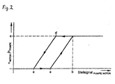
- Figure 2 shows diagrammatically the course of the characteristic curves for the control according to the invention the drive train, in particular the drive train of the embodiment of FIG. 1.
- a gear change can both in the drive train according to the invention automatically depending on the output speed of the mechanical gearbox 8 take place as well as by a corresponding gear selection of the driver via switching inputs of the digital control unit 14 are triggered.
- the electronic control unit 14 checks at any time based on the speed signals of the hydraulic pump 4, the hydraulic motor 5 and Transmission output shaft 13, whether a gear change in automatic shift operation is required or whether a gear change as a result of a manual gear selection when downshifting is even possible.
- the maximum to be taken into account The synchronous speed of the hydraulic motor 5 is determined using the characteristic curve or the so-called Learning curve calculated.
- the characteristic curve of the system denotes the speed ratio of Hydraulic motor 5 to hydraulic pump 4 as a function of the control signal Adjustment device with the hydraulic pump 4, which determines the swivel angle. this applies for the unloaded transmission 8.
- the characteristic curve is set up in the form of a learning curve recorded once for a given powertrain.
- the corresponding output of the electronic control unit 14 is switched off, and that mechanical transmission 8 is for a short moment (about 100 ms) by means of Adjustment device driven without load.
- the control unit 14 guides information from the characteristic curve from.
- the required control signal can be based on the characteristic be determined to the mechanical transmission 8 as quickly as possible in the no-load Driving condition.
- the engine speed i.e. the hydraulic pump speed and / or the speed ratio of hydraulic pump 4 too Hydraulic motor 5 on the basis of the actuating signal or actuating signals to the adjusting device or the adjustment devices of the hydraulic pump 4 and / or hydraulic motor 5 to the flir required gear regulated synchronous speed.
- the corresponding control signal is derived from the learning curve. Is the Speed difference in a certain tolerance range, the control unit 14 switches over a corresponding switching signal the actuator 9 of the selected gear.
- the Switching is complete as soon as the switch 10, which is also the neutral position of the mechanical transmission 8 signals, now the engaged state of the transmission 8th displays.
- the average switching time for a complete switching process is approx. 500 ms.
- the X axis denotes the size of the control signal
- the Y axis denotes that Speed ratio of the hydraulic motor to the hydraulic pump.
- the course of the characteristic curve results from the speed ratio of the hydraulic motor to the hydraulic pump as a function of Actuating signal for adjusting the hydraulic pump and / or hydraulic motor for one no-load state of operation, the speed of the internal combustion engine while recording the characteristic curve in the form of a learning curve during the set-up process is kept constant.
- the individual points of the characteristic curve (a, b, c, d, e) result derive from the structural sizes of the units and the hysteresis characteristics of the Adjustment devices for hydraulic pump and / or hydraulic motor delivery volumes.
- the control unit does not output an adjustment signal, the swivel angle of the Hydraulic pump in the middle position (zero stroke) and the swivel angle of the hydraulic motor in one Position that corresponds to the maximum swallowing volume.
- the swivel angle of the hydraulic pump 4 is first adjusted over the entire range and then the swivel angle of the hydraulic motor moved into the end position, which the corresponds to the minimum swallowing volume.
- the approach point a of the drive train provides one Information about the dead band of the adjustment device.
- the maximum achievable Speed ratio c is at maximum swivel angle of the hydraulic pump and at minimum swivel angle of the hydraulic motor reached. Based on this value, the Control unit 14 depending on the maximum synchronous speed of the hydraulic motor from the control signal and the hydraulic pump speed. The control of the The drive train then takes place in accordance with the above statements.
Landscapes
- Engineering & Computer Science (AREA)
- General Engineering & Computer Science (AREA)
- Mechanical Engineering (AREA)
- Chemical & Material Sciences (AREA)
- Combustion & Propulsion (AREA)
- Transportation (AREA)
- Control Of Transmission Device (AREA)
Description
- Fig. 1
- eine schematische Ansicht einer Ausführungsform des erfindungsgemäßen Antriebsstrangs; und
- Fig. 2
- ein Diagramm mit der Kennlinie.
Claims (13)
- Antriebsstrang für ein Fahrzeug, welcher eine Verbrennungskraftmaschine (1), ein mittels einer elektronischen Steuereinheit (14) und mittels Betätigungseinrichtungen (9) schaltbares kupplungsloses Getriebe (8) mit zumindest zwei Übersetzungsstufen und ein hydrostatisches Getriebe (4, 5) aufweist, dessen Hydropumpe (4) und Hydromotor (5) im geschlossenen Kreis (11) verbunden sind, wobei die Drehzahl des Hydromotors (5) in Abhängigkeit von einem Stellsignal zur Verstelleinrichtung (3) der Hydropumpe (4) und/oder zur Verstelleinrichtung (16) des Hydromotors (5) steuerbar ist, welches die Steuereinheit (14) mittels Sollwertvorgabe über ein Fahrpedal oder als Funktion der Antriebsdrehzahl der Verbrennungskraftmaschine (1) berechnet, wobei die Übersetzungsstufen mittels der Betätigungseinrichtungen (9) schaltbar sind,
gekennzeichnet durch eine derartige Ausbildung der Steuereinheit (14), dass diese die Verstelleinrichtung (3) der Hydropumpe (4) sowie die Betätigungseinrichtungen (9) für das Getriebe (8) zu dessen elektronischer Synchronisation mittels einer Kennlinie steuert, welche das Drehzahlverhältnis des Hydromotors (5) zu der Hydropumpe (4) in Abhängigkeit von einem Stellsignal zur Verstelleinrichtung (3, 16) der Hydropumpe (4) und/oder des Hydromotors (5) für einen lastfreien Zustand des Getriebes (8) darstellt. - Antriebsstrang nach Anspruch 1, dadurch gekennzeichnet, dass zum Verstellen der Hydropumpe (4) deren Schwenkwinkel (Fördervolumen) mittels eines Proportionalventils (3) verstellbar ist, dessen erforderliches Stellsignal (J) die Steuereinheit (14) auf Basis der Sollwertvorgabe über ein Fahrpedal oder in Abhängigkeit von der Antriebsdrehzahl der Verbrennungskraftmaschine (1) liefert, welche mittels eines ersten Drehzahlsensors (2) aufnehmbar ist
- Antriebsstrang nach Anspruch 2, dadurch gekennzeichnet, dass am Getriebe (8) ein Schalter (10) vorgesehen ist, welcher ein Signal an die Steuereinheit (14) liefert, ob sich das Getriebe (8) in Neutralposition befindet oder eine Übersetzungsstufe (Gang) eingekuppelt ist.
- Antriebsstrang nach Anspruch 3, dadurch gekennzeichnet, dass die Betätigungseinrichtungen (9) Ventile oder Elektromagnete sind, welche von der Steuereinheit (14) ansteuerbar und mittels Federkraft wieder auskuppelbar sind, sobald ein entsprechendes Schaltsignal (K, L, M) der Steuereinheit (14) zurückgesetzt und das Getriebe (8) mittels des Stellsignals (J), das anhand der Kennlinie ermittelt wird, in einen lastfreien Zustand gesteuert wird.
- Antriebsstrang nach einem der Ansprüche 1 bis 4, dadurch gekennzeichnet, dass ein zweiter Drehzahlsensor (6) zur Messung der Eingangsdrehzahl des Getriebes (8) und ein dritter Drehzahlsensor (7) zur Messung der Abtriebsdrehzahl des Getriebes (8) zur elektronischen Synchronisation des Getriebes (8) vorgesehen sind.
- Verfahren zum Steuern eines Antriebsstranges mit einer Verbrennungskraftmaschine (1), einem kupplungslosen Getriebe (8) ohne mechanische Synchronisationseinrichtung und einem hydrostatischen Antrieb (4, 5) mit verstellbarer Hydropumpe (4), gegebenenfalls verstellbarem Hydromotor (5) und einer Steuereinheit (14), wobei zum Gangwechsel des Getriebes (8) dieses mittels des hydrostatischen Antriebs (4, 5) lastfrei gefahren und die Drehzahl des Hydromotors (5) auf die für einen gewählten Gang des Getriebes (8) erforderliche Synchrondrehzahl geregelt wird, indem die Steuereinheit (14) eine maximal erreichbare Synchrondrehzahl des Hydromotors (5) mittels einer Kennlinie berechnet, welche das Drehzahlverhältnis von Hydromotor (5) zu Hydropumpe (4) in Abhängigkeit von einem Stellsignal zur Verstelleinrichtung der Hydropumpe (4) und/oder zur Verstelleinrichtung des Hydromotors (5) für einen lastfreien Zustand des Getriebes (8) darstellt.
- Verfahren nach Anspruch 6, wobei die Kennlinie in Form einer Lernkurve als Set-up vor Inbetriebnahme des Antriebsstranges ermittelbar und in der Steuereinheit (14) speicherbar ist, wobei die Stellsignale (J, O) zu den Verstelleinrichtungen (3, 16) von Hydropumpe (4) und/oder Hydromotor (5) solange kontinuierlich erhöht werden, bis das maximale Drehzahlverhältnis von Hydromotor zu Hydropumpe erreicht wird.
- Verfahren nach Anspruch 6 oder 7, wobei die Steuereinheit (14) Betätigungseinrichtungen (9) für Übersetzungsstufen des Getriebes (8) entsprechend einem gewünschten Arbeitspunkt auf der Kennlinie ansteuert.
- Verfahren nach einem der Ansprüche 6 bis 8, wobei die Kennlinie in Form einer Lernkurve als Set-up zumindest für jeden neuen hydrostatischen Antrieb aufgenommen wird.
- Verfahren nach Anspruch 9, wobei die Kennlinie im laufenden Betrieb zur Kompensation von insbesondere verschleiß- und alterungsbedingten Änderungen des hydrostatischen Antriebs (4, 5) korrigiert wird.
- Verfahren nach einem der Ansprüche 8 bis 10, wobei die jeweils aktuelle Übersetzungsstufe während der Fahrt in die neutrale Position geschaltet wird, indem ein entsprechender Ausgang (K, L, M) der Steuereinheit (14) abgeschaltet und das Getriebe (8) kurzzeitig über eine Änderung des Stellsignals zur Verstelleinrichtung der Hydropumpe (4) in den lastfreien Zustand gefahren wird.
- Verfahren nach Anspruch 11, wobei das Getriebe (8) während etwa 100 ms im lastfreien Zustand gefahren wird.
- Verfahren nach Anspruch 8 bis 12, wobei bei Erfassen einer neutralen Position des Getriebes (8) die Antriebsdrehzahl des Hydromotors (5) anhand eines des Schwenkwinkel von Hydropumpe (4) und/oder Hydromotor (5) bestimmenden, aus der Lernkurve abgeleiteten Stellsignals (J, O) schnell auf eine für die gewünschte Übersetzungsstufe erforderliche Synchrondrehzahl geregelt wird.
Applications Claiming Priority (2)
| Application Number | Priority Date | Filing Date | Title |
|---|---|---|---|
| DE19901443 | 1999-01-15 | ||
| DE1999101443 DE19901443B4 (de) | 1999-01-15 | 1999-01-15 | Antriebsstrang für ein Fahrzeug und Verfahren zum Steuern eines Antriebsstranges |
Publications (3)
| Publication Number | Publication Date |
|---|---|
| EP1020314A2 EP1020314A2 (de) | 2000-07-19 |
| EP1020314A3 EP1020314A3 (de) | 2002-04-10 |
| EP1020314B1 true EP1020314B1 (de) | 2003-10-22 |
Family
ID=7894403
Family Applications (1)
| Application Number | Title | Priority Date | Filing Date |
|---|---|---|---|
| EP00100182A Expired - Lifetime EP1020314B1 (de) | 1999-01-15 | 2000-01-12 | Antriebsstrang für ein Fahrzeug und Verfahren zum Steuern eines Antriebsstranges |
Country Status (2)
| Country | Link |
|---|---|
| EP (1) | EP1020314B1 (de) |
| DE (1) | DE19901443B4 (de) |
Families Citing this family (13)
| Publication number | Priority date | Publication date | Assignee | Title |
|---|---|---|---|---|
| DE10104420A1 (de) * | 2001-02-01 | 2002-08-08 | Zahnradfabrik Friedrichshafen | Synchrongetriebe |
| DE10208204B4 (de) * | 2001-02-28 | 2015-02-05 | Schaeffler Technologies Gmbh & Co. Kg | Verfahren zur Inbetriebnahme eines Kraftfahrzeugs |
| DE10133358B4 (de) * | 2001-07-10 | 2006-03-16 | Brueninghaus Hydromatik Gmbh | Hydrostatischer Antrieb und Verfahren zum Wechseln von Gängen eines einem hydrostatischen Getriebe nachgeschalteten Schaltgetriebes |
| DE10260480A1 (de) * | 2002-12-21 | 2004-07-01 | Deere & Company, Moline | Antriebssystem einer selbstfahrenden Arbeitsmaschine |
| RU2264572C1 (ru) * | 2004-04-02 | 2005-11-20 | Открытое акционерное общество "Инновационная фирма "НАМИ-СЕРВИС" | Система управления гидрообъемной трансмиссией многоколесной транспортной машины |
| ITMI20052099A1 (it) * | 2005-11-04 | 2007-05-05 | Laverda S P A | Trasmissi0ne meccanica-idrostatica a gesdtione elettronica per macchine operatrici e trattrioci agricole |
| DE102006036317A1 (de) * | 2006-06-28 | 2008-01-03 | Brueninghaus Hydromatik Gmbh | Verfahren zur Steuerung eines Übersetzungsverhältnisses |
| DE102012023155A1 (de) * | 2012-11-28 | 2014-05-28 | Daimler Ag | Kraftfahrzeugantriebsstrangvorrichtung mit einem hydrostatischen Leistungspfad |
| US8810418B2 (en) * | 2012-11-29 | 2014-08-19 | GM Global Technology Operations LLC | Vehicle fluid regulator valve diagnostic system |
| DE102012024068A1 (de) | 2012-12-10 | 2014-06-12 | Claas Industrietechnik Gmbh | Getriebeaggregat für eine landwirtschaftliche Maschine |
| EP3009716A1 (de) | 2014-10-16 | 2016-04-20 | Dana Italia S.p.A. | Zweimotorige Antriebseinheit und Verfahren zur kraftbetriebenen Kopplung einer ersten zweimotorigen Antriebseinheit mit einer Antriebswelle |
| DE102015110002B4 (de) | 2014-11-04 | 2026-04-23 | Sauer Bibus Gmbh | Hydrostatischer Antrieb mit Schaltgetriebe |
| DE102021204772A1 (de) | 2021-05-11 | 2022-11-17 | Robert Bosch Gesellschaft mit beschränkter Haftung | Verfahren zur Unterstützung des Gangeinlegens von Stillstandsschaltgetrieben |
Family Cites Families (4)
| Publication number | Priority date | Publication date | Assignee | Title |
|---|---|---|---|---|
| EP0282010B1 (de) * | 1987-03-09 | 1992-06-03 | Hydromatik GmbH | Antriebseinrichtung, bestehend aus einem Antriebsmotor wechselnder Drehzahl, einem verstellbaren hydrostatischen Getriebe und einer schaltbaren Einrichtung |
| DE3807599A1 (de) * | 1988-03-08 | 1989-09-28 | Hydromatik Gmbh | Automotive antriebseinrichtung fuer maschinen und fahrzeuge |
| DE19524189C2 (de) * | 1995-07-03 | 1997-07-17 | Brueninghaus Hydromatik Gmbh | Hydrostatischer Antrieb mit nachgeschaltetem Lastschaltgetriebe |
| DE19753729C1 (de) * | 1997-12-04 | 1999-05-12 | Zahnradfabrik Friedrichshafen | Fahrantrieb |
-
1999
- 1999-01-15 DE DE1999101443 patent/DE19901443B4/de not_active Expired - Fee Related
-
2000
- 2000-01-12 EP EP00100182A patent/EP1020314B1/de not_active Expired - Lifetime
Also Published As
| Publication number | Publication date |
|---|---|
| DE19901443A1 (de) | 2000-08-03 |
| DE19901443B4 (de) | 2005-09-22 |
| EP1020314A2 (de) | 2000-07-19 |
| EP1020314A3 (de) | 2002-04-10 |
Similar Documents
| Publication | Publication Date | Title |
|---|---|---|
| DE10080639B4 (de) | Kupplungssteuervorrichtung zur automatischen Betätigung einer Kupplung während des Anfahrens | |
| DE69616060T2 (de) | Motorsteuerungsverfahren beim gangschalten eines handschaltgetriebes | |
| DE2456509C3 (de) | Elektrische Steuereinrichtung für die Kupplungsbetätigung einer durch Federkraft eingerückt gehaltenen Kupplung eines Kraftfahrzeugs, insbesondere eines Lastkraftfahrzeugs | |
| EP0339202B1 (de) | Antriebseinrichtung für Maschinen und Fahrzeuge | |
| DE602004000650T2 (de) | Steuerverfahren für ein Doppelkupplungsgetriebe | |
| EP0832370B1 (de) | System zur steuerung einer servokupplung | |
| EP2118511A1 (de) | Verfahren zur dynamischen ermittlung eines kupplungs-ruhepunktes | |
| DE112004000130T5 (de) | Stufenlos veränderbares Getriebe | |
| DE102011017516B4 (de) | Verfahren zur Bestimmung von Kenngrößen eines Automatikgetriebes | |
| DE19901443B4 (de) | Antriebsstrang für ein Fahrzeug und Verfahren zum Steuern eines Antriebsstranges | |
| EP0545298A1 (de) | Fahrzeugantriebsstrang mit hydraulisch gesteuertem Schaltgetriebe | |
| EP1812735B1 (de) | Verfahren zum betrieb eines antriebsstrangs eines kraftfahrzeugs | |
| DE69716416T2 (de) | Steuersystem für ein stufenloses getriebe | |
| DE102006013040B4 (de) | Kupplungssteuervorrichtung | |
| DE19735759B4 (de) | Vorrichtung und Verfahren zum Steuern einer automatischen Antriebsvorrichtung | |
| DE60013292T2 (de) | Schaltsynchronisation die ein abfallendes Drehmoment berücksichtigt | |
| EP1277991B1 (de) | Hydrostatischer Antrieb und Schaltverfahren | |
| DE69104433T2 (de) | Fahrzeuggetriebe. | |
| DE19861303B4 (de) | Stufengetriebe und Verfahren zum Auslegen eines Ganges eines Stufengetriebes | |
| EP1238215B1 (de) | Kraftfahrzeuggetriebe mit zwei schaltkraftverlaufsbereichen | |
| DE3425757A1 (de) | Synchronisiertes mechanisch-hydrostatisches getriebe | |
| DE3903010B4 (de) | Verfahren zur Steuerung eines stufenlosen hydrostatisch mechanischen Verzweigungsgetriebes | |
| EP1718883A1 (de) | Verfahren und vorrichtung zur steuerung von anfahr-, fahr- oder schaltvorgängen eines kraftfahrzeuges | |
| DE10065725A1 (de) | Verfahren zum Betreiben eines Antriebsstrangs eines Kraftfahrzeugs und Regelungseinrichtung zur Durchführung des Verfahrens | |
| WO2005064208A1 (de) | Verfahren zum betrieb eines antriebsstrangs eines kraftfahrzeugs |
Legal Events
| Date | Code | Title | Description |
|---|---|---|---|
| PUAI | Public reference made under article 153(3) epc to a published international application that has entered the european phase |
Free format text: ORIGINAL CODE: 0009012 |
|
| AK | Designated contracting states |
Kind code of ref document: A2 Designated state(s): AT BE CH CY DE DK ES FI FR GB GR IE IT LI LU MC NL PT SE Kind code of ref document: A2 Designated state(s): IT |
|
| AX | Request for extension of the european patent |
Free format text: AL;LT;LV;MK;RO;SI |
|
| RAP1 | Party data changed (applicant data changed or rights of an application transferred) |
Owner name: SAUER-DANFOSS (NEUMUENSTER) GMBH & CO. OHG Owner name: MERLO S.P.A. INDUSTRIA METALMECCANICA |
|
| PUAL | Search report despatched |
Free format text: ORIGINAL CODE: 0009013 |
|
| AK | Designated contracting states |
Kind code of ref document: A3 Designated state(s): AT BE CH CY DE DK ES FI FR GB GR IE IT LI LU MC NL PT SE |
|
| AX | Request for extension of the european patent |
Free format text: AL;LT;LV;MK;RO;SI |
|
| RIC1 | Information provided on ipc code assigned before grant |
Free format text: 7B 60K 17/10 A, 7F 16H 47/02 B |
|
| 17P | Request for examination filed |
Effective date: 20020918 |
|
| 17Q | First examination report despatched |
Effective date: 20021114 |
|
| AKX | Designation fees paid |
Free format text: IT |
|
| REG | Reference to a national code |
Ref country code: DE Ref legal event code: 8566 |
|
| GRAH | Despatch of communication of intention to grant a patent |
Free format text: ORIGINAL CODE: EPIDOS IGRA |
|
| GRAS | Grant fee paid |
Free format text: ORIGINAL CODE: EPIDOSNIGR3 |
|
| GRAA | (expected) grant |
Free format text: ORIGINAL CODE: 0009210 |
|
| AK | Designated contracting states |
Kind code of ref document: B1 Designated state(s): IT |
|
| REG | Reference to a national code |
Ref country code: IE Ref legal event code: FG4D Free format text: GERMAN |
|
| REG | Reference to a national code |
Ref country code: IE Ref legal event code: FD4D |
|
| PLBE | No opposition filed within time limit |
Free format text: ORIGINAL CODE: 0009261 |
|
| STAA | Information on the status of an ep patent application or granted ep patent |
Free format text: STATUS: NO OPPOSITION FILED WITHIN TIME LIMIT |
|
| 26N | No opposition filed |
Effective date: 20040723 |
|
| PGRI | Patent reinstated in contracting state [announced from national office to epo] |
Ref country code: IT Effective date: 20110501 |
|
| PG25 | Lapsed in a contracting state [announced via postgrant information from national office to epo] |
Ref country code: IT Free format text: LAPSE BECAUSE OF NON-PAYMENT OF DUE FEES Effective date: 20110112 |
|
| PGRI | Patent reinstated in contracting state [announced from national office to epo] |
Ref country code: IT Effective date: 20120920 |
|
| PGFP | Annual fee paid to national office [announced via postgrant information from national office to epo] |
Ref country code: IT Payment date: 20170123 Year of fee payment: 18 |
|
| PG25 | Lapsed in a contracting state [announced via postgrant information from national office to epo] |
Ref country code: IT Free format text: LAPSE BECAUSE OF NON-PAYMENT OF DUE FEES Effective date: 20180112 |