EP1019652B1 - Ableiter - Google Patents
Ableiter Download PDFInfo
- Publication number
- EP1019652B1 EP1019652B1 EP98945419A EP98945419A EP1019652B1 EP 1019652 B1 EP1019652 B1 EP 1019652B1 EP 98945419 A EP98945419 A EP 98945419A EP 98945419 A EP98945419 A EP 98945419A EP 1019652 B1 EP1019652 B1 EP 1019652B1
- Authority
- EP
- European Patent Office
- Prior art keywords
- body section
- reservoir
- end caps
- liquid
- drain device
- Prior art date
- Legal status (The legal status is an assumption and is not a legal conclusion. Google has not performed a legal analysis and makes no representation as to the accuracy of the status listed.)
- Expired - Lifetime
Links
- 239000007788 liquid Substances 0.000 claims description 43
- 230000015572 biosynthetic process Effects 0.000 claims description 7
- 238000007789 sealing Methods 0.000 claims description 4
- 238000007599 discharging Methods 0.000 claims description 3
- 239000000463 material Substances 0.000 description 7
- 238000005755 formation reaction Methods 0.000 description 6
- 238000000465 moulding Methods 0.000 description 6
- 238000001125 extrusion Methods 0.000 description 4
- 238000000034 method Methods 0.000 description 4
- 229910000838 Al alloy Inorganic materials 0.000 description 3
- 238000004519 manufacturing process Methods 0.000 description 3
- 230000013011 mating Effects 0.000 description 3
- 229910045601 alloy Inorganic materials 0.000 description 2
- 239000000956 alloy Substances 0.000 description 2
- 238000005266 casting Methods 0.000 description 2
- 238000010276 construction Methods 0.000 description 2
- 239000012530 fluid Substances 0.000 description 2
- 239000012535 impurity Substances 0.000 description 2
- 239000007769 metal material Substances 0.000 description 2
- 239000000523 sample Substances 0.000 description 2
- OKTJSMMVPCPJKN-UHFFFAOYSA-N Carbon Chemical compound [C] OKTJSMMVPCPJKN-UHFFFAOYSA-N 0.000 description 1
- 229920000181 Ethylene propylene rubber Polymers 0.000 description 1
- 239000004952 Polyamide Substances 0.000 description 1
- 230000002411 adverse Effects 0.000 description 1
- 239000004411 aluminium Substances 0.000 description 1
- 229910052782 aluminium Inorganic materials 0.000 description 1
- XAGFODPZIPBFFR-UHFFFAOYSA-N aluminium Chemical compound [Al] XAGFODPZIPBFFR-UHFFFAOYSA-N 0.000 description 1
- 229910052799 carbon Inorganic materials 0.000 description 1
- 239000004020 conductor Substances 0.000 description 1
- 238000005520 cutting process Methods 0.000 description 1
- 230000002708 enhancing effect Effects 0.000 description 1
- 210000004907 gland Anatomy 0.000 description 1
- 239000011521 glass Substances 0.000 description 1
- 238000001746 injection moulding Methods 0.000 description 1
- 238000003754 machining Methods 0.000 description 1
- 238000012423 maintenance Methods 0.000 description 1
- 239000002184 metal Substances 0.000 description 1
- 229910052751 metal Inorganic materials 0.000 description 1
- 239000003921 oil Substances 0.000 description 1
- 229920002647 polyamide Polymers 0.000 description 1
- 229920000515 polycarbonate Polymers 0.000 description 1
- 239000004417 polycarbonate Substances 0.000 description 1
- 229920000728 polyester Polymers 0.000 description 1
- 230000002787 reinforcement Effects 0.000 description 1
- 229920002379 silicone rubber Polymers 0.000 description 1
- 239000000126 substance Substances 0.000 description 1
- 230000000007 visual effect Effects 0.000 description 1
- XLYOFNOQVPJJNP-UHFFFAOYSA-N water Substances O XLYOFNOQVPJJNP-UHFFFAOYSA-N 0.000 description 1
Images

Classifications
-
- F—MECHANICAL ENGINEERING; LIGHTING; HEATING; WEAPONS; BLASTING
- F16—ENGINEERING ELEMENTS AND UNITS; GENERAL MEASURES FOR PRODUCING AND MAINTAINING EFFECTIVE FUNCTIONING OF MACHINES OR INSTALLATIONS; THERMAL INSULATION IN GENERAL
- F16T—STEAM TRAPS OR LIKE APPARATUS FOR DRAINING-OFF LIQUIDS FROM ENCLOSURES PREDOMINANTLY CONTAINING GASES OR VAPOURS
- F16T1/00—Steam traps or like apparatus for draining-off liquids from enclosures predominantly containing gases or vapours, e.g. gas lines, steam lines, containers
- F16T1/38—Component parts; Accessories
Definitions
- This invention relates to a drain device which might be used for discharging liquid from a pressurised gas system.
- Gas in pressurised gas systems frequently contains a small amount of impurities such as cracked oils or water. These impurities tend to condense out of the gas over time and accumulate. Eventually, this condensate can affect the performance of the gas system adversely.
- US-5469879 discloses a condensate removal device for capturing, measuring and removing condensate from a fluid system which contains air or or another gas under pressure.
- a single sensing probe extends into a vertically arranged condensate collection reservoir to sense the low and high level of condensate, and signals from the probe activate a diaphragm type discharge valve through which condensate can be discharged from the reservoir. Once condensate levels fall below a pre-determined level within the reservoir, the valve is closed while condensate continues accummulates again.
- US-4974626 discloses a device which includes a reservoir for collecting a condensate, and capacitive sensors determining the level of the condensate in the reservoir. Collected condensate is discharged through a diaphragm outlet valve.
- the reservoir is formed as a two-piece moulded hollow body. The top and bottom pieces hollow body have features formed in them by moulding including inlets and outlets for fluid, and mounts for the outlet valve and for level sensors.
- the invention provides a drain device for discharging liquid from a pressurised gas system, which comprises a reservoir for the liquid and a liquid outlet through which liquid can be discharged from the reservoir, the reservoir being defined by a body section whose cross-section is substantially constant along its length, and by first and second end caps which have on them the inlet and the outlet for the gas in which the liquid is transported, and which are positioned at opposite ends of the body section and are separable from the body section, the reservoir being arranged for use with the body section extending substantially horizontally with the end caps providing the end walls, one of the end caps including a level sensor for sensing the level of liquid in the reservoir.
- the drain device of the present invention has the advantage that it can be built with a capacity to suit the requirements of a particular application by adjusting the length of the body section.
- Common end caps can be used for devices with reservoirs having a range of capacities.
- This flexibility of design has advantages for the user because products can be built to meet the requirements of his application.
- the flexibility has advantages for the manufacturer of the device because a range of products can be made without the need to make different components for each individual product.
- the inventory of components that the manufacturer is required to maintain for manufacture of a range of products, as well as the range of equipment such as moulds for manufacturing those components, is also minimised.
- the device of the invention can be made by a method which comprises forming a body section of the device by extrusion, cutting the body section to an appropriate length, and fastening the body section at each of its ends to respective end caps.
- the end caps will generally be formed by a moulding process.
- the moulding process might be, for example, injection moulding. It will often be preferred for the end caps to be formed from a metal. They might then suitably be formed by casting.
- one or more of the end caps will have features of the drain device formed in them.
- These features might include for example inlets and outlets for pressurised gas, outlets for collected liquid, formations for engaging the outlet valve, openings for control components and so on. Some or all of these feature might be formed in the end caps as a result of the moulding process by which the end caps are formed.
- the features might be added to the end caps in a manufacturing step after the moulding step; the features might be modified or optimised after the moulding step for example by machining.
- the inlet for the compressed gas and the outlet for collected liquid can be provided in a common end cap.
- the inlet for the compressed gas is provided in one of the end caps and the outlet for collected liquid will generally be provided in the other of the end caps.
- An end cap in which the inlet and outlet for compressed gas are provided can have a plurality of inlets or a plurality of outlets or both, in different relative orientations. Appropriate blanks can be used to select the inlet or outlet for a particular application.
- the end cap in which the outlet for collected liquid is provided will generally include formations by which an outlet valve can be mounted on the end cap, to control the discharge of liquid from the reservoir.
- One of the end caps can include appropriate mounts for at least one sensor by which the level of liquid in the reservoir can be monitored. Signals from the sensor(s) can be used to control the outlet valve. It will often be preferred for the sensors to be mounted on the same end cap as the outlet valve to simplify connections between the sensors and the valve.
- the end cap with the outlet valve might also include formations for mounting other control equipment including for example connections to an external power supply or a dedicated power supply, indicators (for example of an alarm condition), and so on.
- the body section of the reservoir has at least one channel formed in it to receive an elongate fastener by which the body section can be fastened to one of the end caps.
- the channel extends through the body section from one of the end caps to the other.
- Such a channel might accommodate a fastener which extends through the channel from one of the end caps to the other.
- a channel in the body section can provide protection of the fastener from impact damage. The location of the fastener in a channel can make more secure the location of the body section with respect to the end caps, in particular against impact.
- Each of the end caps might have an opening formed in it which can be aligned with a corresponding channel in the body section when the valve is assembled, so that the elongate fastener can be located in the channel with its ends received in the openings in the end caps.
- the channel in the body section can be threaded to form a threaded connection with a fastener inserted therein.
- a fastener which extends through the body section from one end to the other
- the fastener can then apply a compressive load to the assembly of the end caps and the body section.
- a fastener is sometimes referred to as a tie rod.
- the cross-section of the or each channel is closed. This has the advantage of enhancing the protection afforded to the fastener(s) by the channel and to the connection between the body section and the end caps.
- the body section has a plurality of channels formed in it spaced apart around the periphery of the body section.
- the channels are spaced apart substantially symmetrically around the axis. This can enhance the reliability of the seal between the body section and the end caps.
- a sealing member is provided between at least one of the end caps and the mating face of the body section.
- the sealing member might take the form of, for example, a compressible gasket.
- the material of the gasket will be selected according to the substances with which it will come into contact when in use. Examples of suitable materials might include for example silicone rubbers, ethylene propylene rubbers and so on.
- a formation might be provided in at least one of the facing surfaces of one of the end caps and the corresponding end wall of the body section for locating a sealing member. For example, a groove might be formed in one or both of the end walls of the body section in which an O-ring can be received.
- the materials of the end caps and the body section are substantially the same so that for example their thermal expansion coefficients are similar. This can make the seal between the end caps and the body section less vulnerable to changes in ambient conditions, especially temperature.
- the body section together with the end caps to be formed from metallic materials or for them all to be formed from polymeric materials.
- Particularly preferred metallic materials for the end caps or the body section or both include aluminium and its alloys.
- An example of a suitable aluminium alloy is HE30TF which has appropriate high tensile strength and contains appropriate alloy components which facilitate formation of the section by extrusion.
- Appropriate polymeric materials might include for example polyamides, polyesters, polycarbonates and the like.
- Polymeric materials used in the drain device can include fibres for reinforcement, for example fibres of glass or of carbon.
- the internal cross-section of the body section will preferably be generally rounded, especially circular. This has the advantage of being able to withstand high internal pressures.
- the internal cross-sectional area of the body section will often be at least about 100 cm 2 , preferably at least about 150 cm 2 .
- the cross-sectional area will generally be less than about 1200 cm 2 , and often less than about 400 cm 2 .
- the length of the body section will often be at least about 3 cm, preferably at least about 6 cm, more preferably at least about 10 cm.
- the length of the body section will often be less than about 60 cm, preferably less than about 45 cm.
- the volume of the reservoir will generally be at least about 500 cm 3 .
- the volume will generally be less than about 8000 cm 3 .
- the drain device has the advantage that a common end cap can be used to form the reservoir irrespective of the volume of the reservoir: the volume can be selected by use of a body section with appropriate dimensions.
- the sensor can cause an open signal to be suppled to a discharge valve when the liquid level in the reservoir exceeds a predetermined level.
- the valve can then remain open until the liquid level drops to below a second predetermined level, when the sensor can cause a close signal to be supplied to the valve.
- This arrangement has the advantage that the sensor can be used in drain devices with a range of volumes without having to be recalibrated according to the reservoir volume.
- the valve might remain open for a predetermined period which is selected according to the volume of liquid in the reservoir that should be discharged. In this arrangement, the period for which the discharge valve remains open might have to be changed according to the volume of the reservoir.
- the drain device When the drain device is arranged horizontally in use, it will often have a low aspect ratio so that its height is less than its length (the length being measured along the axis of the reservoir). This can have the advantage that significant changes in the volume of liquid in the reservoir involve relatively small changes in the depth of the liquid. This can be arranged to reduce the frequency with which the discharge valve has to open to be minimised, with the advantage that there is reduced wear on component of the drain device.
- the level sensor is a capacitive sensor.
- one of the electrodes of the capacitive sensor is provided by the body of the end cap itself.
- At least one of (a) the inlet for the gas in which the liquid is transported, (b) the outlet for the said gas, and (c) the drain for collected liquid, is provided in the end cap.
- Those elements which are not provided in the end cap can be provided in another part of the reservoir.
- the drain device with the level sensor in its end cap can incorporate any of the features referred to above in relation to the drain device of the other aspect of the invention.
- the axis of the body section will preferably then be arranged horizontally when the device is in use.
- a reservoir with a constant cross-section can then be defined by a second end cap positioned at the end of the body section opposite to the end cap with the level sensor.
- This construction optimises the advantage of the flexibility of design (in particularly in terms of capacity of the reservoir) that is made possible by incorporating the level sensor in the end cap.
- the inlet and the outlet for the gas in which the liquid is transported are provided in one of the end caps and the outlet for collected liquid is provided in the other of the end caps.
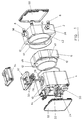
- Figure 1 shows a drain device which comprises a first end cap 2, a second end cap 4 and a body section 6 between them.
- the end caps are formed from an aluminium alloy by casting.
- the body section has a constant cross-section along its length (apart from features machined to the end faces as described below) and is formed from an aluminium alloy by extrusion.
- Figure 2 shows the second end cap 2 in more detail. It has formed in it an outlet 20 for liquid that has accumulated in the reservoir defined by the end caps and the body section. Threaded openings are provided in an external face 22 of the second end cap by which a valve 24 can be attached to the second end cap.
- the second end cap has an opening 26 for a capacitive sensor 28 for the level of liquid in the reservoir.
- the sensor 28 detects when the level of liquid exceeds a predetermined maximum level. Signals generated by the sensor are used to cause the valve 24 to open to maintain the level of liquid in the reservoir below the said maximum level.
- the valve remains open for a predetermined time which is set appropriately to ensure that liquid drains from the reservoir to a level which is at an appropriate minimum level.
- the sensor can be used to detect when the level of liquid is less than a predetermined minimum level to generate a signal to cause the valve to close, instead of the use of a timer.
- the sensor might comprise separate sensing elements for sensing each of the liquid levels.
- the level sensor 28 is arranged to detect the level of liquid in the reservoir as it changes up and down the end faces of the reservoir provided by the first and second end caps, that is with the reservoir arranged so that its axis is substantially horizontal.
- the length of the body section is larger than its height (when arranged with its axis horizontal)
- a significant increase in volume of liquid in the reservoir involves only a small change in the depth of the liquid.
- the level sensor (and each sensing element within the sensor if there is more than one) can be a capacitive sensor.
- One of the electrodes of the sensor can be provided by the end cap of the reservoir.
- the sensor is provided on a module 32 which is received in the opening 26 in the second end cap with appropriate seals provided between the module and the opening.
- the module can incorporate other components for controlling the device, including for example a transformer, battery, alarm indicators (visual or audible), or data processing components.
- the module has glands 33 for conductors, for example to supply power to the module or to allow a signal to be conducted to or from the module.
- the provision of control components on a module has the advantage of simplifying construction of the end cap since the number of features provided on the end cap for the components can be kept to a minimum. This can simplify assembly since the number of seals that are required for components mounted on the end cap is kept to a minimum. Maintenance of the end cap is simplified since, in the event of failure of a component, a repair can be effected simply and quickly by replacement of the module.
- the first end cap 2 has a pair of inlets 34, 36 for liquid that is to be drained allowing the device to be connected in two different orientations with one of the inlets being used for the liquid to be drained while the other inlet is blocked by an appropriate blanking insert 38.
- Each of the end caps has a groove 42 formed in its end face for receiving a gasket 44.
- Figure 3 shows the body section 6 in more detail. It has a constant cross-section as a result of being formed by extrusion. It has a main reservoir cavity 40 and four small openings 12 spaced evenly around the periphery of the reservoir cavity, for receiving the bolts 8. The capacity of the reservoir is then determined by the length of the body section thereof.
- a rib 46 is formed on each of the end faces of the body section for compressing the gasket 44 in each of the mating end faces of the end caps, to a seal between the body section and the end caps.
- Closure covers 50, 52, 54 are provided for the first end cap 2, the second end cap 4 and the module 32 respectively.
Landscapes
- Engineering & Computer Science (AREA)
- General Engineering & Computer Science (AREA)
- Mechanical Engineering (AREA)
- Measurement Of Levels Of Liquids Or Fluent Solid Materials (AREA)
- Filling Or Discharging Of Gas Storage Vessels (AREA)
Claims (10)
- Abflußvorrichtung zum Austragen von Flüssigkeit aus einem unter Druck stehenden Gassystem, welches ein Reservoir für die Flüssigkeit und einen Flüssigkeitsauslaß (20) umfasst, durch welchen Flüssigkeit aus dem Reservoir ausgetragen werden kann, wobei das Reservoir durch einen Gehäuseabschnitt (6), dessen Querschnitt im wesentlichen entlang seiner Länge konstant ist, und durch eine erste und zweite Endkappe (2, 4) begrenzt wird, welche den Einlaß und den Auslaß für das Gas tragen, in dem die Flüssigkeit transportiert wird, und die an entgegengesetzten Enden des Gehäuseabschnitts (6) angeordnet sind und von dem Gehäuseabschnitt trennbar sind, wobei das Reservoir zur Verwendung so angeordnet ist, daß sich der Gehäuseabschnitt (6) im wesentlichen horizontal erstreckt, wobei die Endkappen (2, 4) die Endwände bereitstellen und eine der Endkappen einen Pegelmeßfühler (28) zum Messen des Flüssigkeitspegels in dem Reservoir umfasst.
- Abflußvorrichtung nach Anspruch 1, in welcher der Pegelmeßfühler (28) ein kapazitiver Meßfühler ist.
- Abflußvorrichtung nach Anspruch 2, in welcher eine der Elektroden des kapazitiven Meßfühlers (28) durch die Endkappe selbst gebildet wird.
- Abflußvorrichtung nach einem der Ansprüche 1 bis 3, in welcher der Auslaß (20) für gesammelte Flüssigkeit an einer der Endkappen vorgesehen ist.
- Abflußvorrichtung nach Anspruch 1, in welcher der Einlaß und der Auslaß für das Gas, in dem die Flüssigkeit transportiert wird, an einer der Endkappen vorgesehen sind und der Auslaß für gesammelte Flüssigkeit an der anderen Endkappe vorgesehen ist.
- Abflußvorrichtung nach Anspruch 1, in welcher in dem Gehäuseabschnitt (6) des Reservoirs mindestens ein Kanal (12) so ausgebildet ist, daß er ein längliches Befestigungselement (8) aufnimmt, durch welches der Gehäuseabschnitt an einer der Endkappen befestigt werden kann.
- Abflußvorrichtung nach Anspruch 6, welche eine darin ausgebildete Mehrzahl von Kanälen (12) umfasst, die symmetrisch um die Längsachse des Gehäuseabschnitts angeordnet sind.
- Abflußvorrichtung nach Anspruch 6 oder Anspruch 7, in welcher der Querschnitt des oder jeden Kanals geschlossen ist.
- Abflußvorrichtung nach einem der Ansprüche 6 bis 8, in welcher jede der Endkappen (2, 4) eine Öffnung (10) aufweist, die mit einem entsprechenden Kanal (12) in dem Gehäuseabschnitt (6) ausgerichtet werden kann, wenn das Reservoir zusammengebaut wird, so daß das längliche Befestigungselement (18) in dem Kanal so angeordnet werden kann, daß seine Enden in den Öffnungen in den Endkappen aufgenommen werden.
- Abflußvorrichtung nach einem der Ansprüche 1 bis 9, in welcher in mindestens einer der gegenüberliegenden Flächen von einer der Endkappen und der entsprechenden Endwand (46) des Gehäuseabschnitts eine Ausgestaltung (42) zur Anordnung eines Dichtungselementes (44) vorgesehen ist.
Applications Claiming Priority (5)
| Application Number | Priority Date | Filing Date | Title |
|---|---|---|---|
| GBGB9720849.0A GB9720849D0 (en) | 1997-10-02 | 1997-10-02 | A drain device |
| GB9720849 | 1997-10-02 | ||
| GBGB9815962.7A GB9815962D0 (en) | 1998-07-23 | 1998-07-23 | Drain device |
| GB9815962 | 1998-07-23 | ||
| PCT/GB1998/002954 WO1999018386A1 (en) | 1997-10-02 | 1998-10-01 | A drain device |
Publications (2)
| Publication Number | Publication Date |
|---|---|
| EP1019652A1 EP1019652A1 (de) | 2000-07-19 |
| EP1019652B1 true EP1019652B1 (de) | 2002-08-28 |
Family
ID=26312350
Family Applications (1)
| Application Number | Title | Priority Date | Filing Date |
|---|---|---|---|
| EP98945419A Expired - Lifetime EP1019652B1 (de) | 1997-10-02 | 1998-10-01 | Ableiter |
Country Status (4)
| Country | Link |
|---|---|
| EP (1) | EP1019652B1 (de) |
| JP (1) | JP2003510525A (de) |
| DE (1) | DE69807510T2 (de) |
| WO (1) | WO1999018386A1 (de) |
Families Citing this family (2)
| Publication number | Priority date | Publication date | Assignee | Title |
|---|---|---|---|---|
| DE102005028632B4 (de) * | 2005-06-20 | 2021-03-04 | Beko Technologies Gmbh | Kondensatableiter mit Wartungsschnittstelle |
| US10376166B2 (en) | 2015-01-19 | 2019-08-13 | Statumanu Icp Aps | Method and apparatus for non-invasive assessment of intracranial pressure |
Family Cites Families (8)
| Publication number | Priority date | Publication date | Assignee | Title |
|---|---|---|---|---|
| BE520643A (de) * | ||||
| DE627069C (de) * | 1933-08-02 | 1936-03-07 | Gustav Friedrich Gerdts | Vorrichtung zum Absperren und Entschlammen von Dampfwasserableitern |
| JPS6056955B2 (ja) * | 1981-11-25 | 1985-12-12 | シ−ケ−デイ株式会社 | ドレン排出器 |
| FR2640354B1 (fr) * | 1988-12-12 | 1991-02-22 | Fontenier Jacques | Dispositif pour purger les residus d'un circuit d'air comprime |
| DE59007183D1 (de) | 1989-04-05 | 1994-10-27 | Berthold Koch | Vorrichtung zum Ableiten von Kondensat aus Drucksystemen oder dergleichen. |
| DE9002152U1 (de) * | 1990-02-23 | 1990-05-10 | Gabriela Lennartz Sondergerätebau, 75233 Tiefenbronn | Entwässerer |
| GB2274317A (en) * | 1993-01-15 | 1994-07-20 | Spirax Sarco Ltd | Condensate trap installations |
| US5469879A (en) * | 1994-05-23 | 1995-11-28 | Rasmussen; John | Condensate trap and drain for systems under pressure |
-
1998
- 1998-10-01 DE DE69807510T patent/DE69807510T2/de not_active Expired - Lifetime
- 1998-10-01 JP JP2000515139A patent/JP2003510525A/ja active Pending
- 1998-10-01 EP EP98945419A patent/EP1019652B1/de not_active Expired - Lifetime
- 1998-10-01 WO PCT/GB1998/002954 patent/WO1999018386A1/en not_active Ceased
Also Published As
| Publication number | Publication date |
|---|---|
| DE69807510D1 (de) | 2002-10-02 |
| DE69807510T2 (de) | 2003-11-13 |
| JP2003510525A (ja) | 2003-03-18 |
| WO1999018386A1 (en) | 1999-04-15 |
| EP1019652A1 (de) | 2000-07-19 |
Similar Documents
| Publication | Publication Date | Title |
|---|---|---|
| US11850539B2 (en) | Fuel filter device | |
| EP4421364A1 (de) | Automatische flüssigkeitsabflussvorrichtung | |
| JPS6449795A (en) | Lubrication monitor for machine | |
| EP1019652B1 (de) | Ableiter | |
| WO1999030802A1 (en) | Filter assembly | |
| US5662791A (en) | Radiator cooling system filter assembly | |
| EP2126330B1 (de) | Reinigungsbaugruppe für ein filtergehäuse | |
| US6173756B1 (en) | Broad side element for a slab mold | |
| EP0085206B1 (de) | Abscheider für komprimierten Gasen | |
| US20050028879A1 (en) | Metal bellows hydraulic accumulator | |
| EP3741918B1 (de) | Aussengehäuse für ein drucküberwachungssystem | |
| EP3088781B1 (de) | Ventilsteller für prozesssteuerungsventile | |
| DE20313289U1 (de) | Trockenlaufschutz | |
| FI3705739T3 (fi) | Suojakansi kierrepultteja varten | |
| KR200237785Y1 (ko) | 동파방지용 수도계량기 | |
| CN109915114B (zh) | 防泥浆组件及封隔系统 | |
| US20040255668A1 (en) | Fluid meter, in particular water meter with volumetric measurement chamber | |
| CN215762499U (zh) | 一种高效液压泵站 | |
| US20060175241A1 (en) | Drain valve insert | |
| CA1116200A (en) | Stuffing box and support therefor | |
| US20140299200A1 (en) | Liquid Condensate Collection and Drain Apparatus for Compressed Air-Gas Systems and Method Therefore | |
| RU2007789C1 (ru) | Погружная аккумуляторная батарея | |
| EP0544214A1 (de) | Sammelvorrichtung zur Anwendung in einem Kältemittelkreislauf | |
| CN221267394U (zh) | 抗冻的大滤瓶净水装置 | |
| US20040231247A1 (en) | Two piece sump cover plate without water inlet |
Legal Events
| Date | Code | Title | Description |
|---|---|---|---|
| PUAI | Public reference made under article 153(3) epc to a published international application that has entered the european phase |
Free format text: ORIGINAL CODE: 0009012 |
|
| 17P | Request for examination filed |
Effective date: 20000327 |
|
| AK | Designated contracting states |
Kind code of ref document: A1 Designated state(s): DE FR GB IT |
|
| 17Q | First examination report despatched |
Effective date: 20010718 |
|
| GRAG | Despatch of communication of intention to grant |
Free format text: ORIGINAL CODE: EPIDOS AGRA |
|
| GRAG | Despatch of communication of intention to grant |
Free format text: ORIGINAL CODE: EPIDOS AGRA |
|
| GRAH | Despatch of communication of intention to grant a patent |
Free format text: ORIGINAL CODE: EPIDOS IGRA |
|
| GRAH | Despatch of communication of intention to grant a patent |
Free format text: ORIGINAL CODE: EPIDOS IGRA |
|
| GRAA | (expected) grant |
Free format text: ORIGINAL CODE: 0009210 |
|
| AK | Designated contracting states |
Kind code of ref document: B1 Designated state(s): DE FR GB IT |
|
| PG25 | Lapsed in a contracting state [announced via postgrant information from national office to epo] |
Ref country code: IT Free format text: LAPSE BECAUSE OF FAILURE TO SUBMIT A TRANSLATION OF THE DESCRIPTION OR TO PAY THE FEE WITHIN THE PRESCRIBED TIME-LIMIT;WARNING: LAPSES OF ITALIAN PATENTS WITH EFFECTIVE DATE BEFORE 2007 MAY HAVE OCCURRED AT ANY TIME BEFORE 2007. THE CORRECT EFFECTIVE DATE MAY BE DIFFERENT FROM THE ONE RECORDED. Effective date: 20020828 |
|
| REG | Reference to a national code |
Ref country code: GB Ref legal event code: FG4D |
|
| REF | Corresponds to: |
Ref document number: 69807510 Country of ref document: DE Date of ref document: 20021002 |
|
| ET | Fr: translation filed | ||
| PLBE | No opposition filed within time limit |
Free format text: ORIGINAL CODE: 0009261 |
|
| STAA | Information on the status of an ep patent application or granted ep patent |
Free format text: STATUS: NO OPPOSITION FILED WITHIN TIME LIMIT |
|
| 26N | No opposition filed |
Effective date: 20030530 |
|
| REG | Reference to a national code |
Ref country code: GB Ref legal event code: 732E |
|
| REG | Reference to a national code |
Ref country code: FR Ref legal event code: TP |
|
| REG | Reference to a national code |
Ref country code: FR Ref legal event code: PLFP Year of fee payment: 19 |
|
| PGFP | Annual fee paid to national office [announced via postgrant information from national office to epo] |
Ref country code: FR Payment date: 20161025 Year of fee payment: 19 Ref country code: GB Payment date: 20161027 Year of fee payment: 19 Ref country code: DE Payment date: 20161027 Year of fee payment: 19 |
|
| REG | Reference to a national code |
Ref country code: DE Ref legal event code: R119 Ref document number: 69807510 Country of ref document: DE |
|
| GBPC | Gb: european patent ceased through non-payment of renewal fee |
Effective date: 20171001 |
|
| REG | Reference to a national code |
Ref country code: FR Ref legal event code: ST Effective date: 20180629 |
|
| PG25 | Lapsed in a contracting state [announced via postgrant information from national office to epo] |
Ref country code: DE Free format text: LAPSE BECAUSE OF FAILURE TO SUBMIT A TRANSLATION OF THE DESCRIPTION OR TO PAY THE FEE WITHIN THE PRESCRIBED TIME-LIMIT Effective date: 20180501 Ref country code: GB Free format text: LAPSE BECAUSE OF NON-PAYMENT OF DUE FEES Effective date: 20171001 |
|
| PG25 | Lapsed in a contracting state [announced via postgrant information from national office to epo] |
Ref country code: FR Free format text: LAPSE BECAUSE OF NON-PAYMENT OF DUE FEES Effective date: 20171031 |