EP1019643B1 - Dispositif d'equilibrage pour roue et roue equipee d'un tel dispositif d'equilibrage - Google Patents
Dispositif d'equilibrage pour roue et roue equipee d'un tel dispositif d'equilibrage Download PDFInfo
- Publication number
- EP1019643B1 EP1019643B1 EP98946551A EP98946551A EP1019643B1 EP 1019643 B1 EP1019643 B1 EP 1019643B1 EP 98946551 A EP98946551 A EP 98946551A EP 98946551 A EP98946551 A EP 98946551A EP 1019643 B1 EP1019643 B1 EP 1019643B1
- Authority
- EP
- European Patent Office
- Prior art keywords
- balancing
- weight
- wheel
- tyre
- rim
- Prior art date
- Legal status (The legal status is an assumption and is not a legal conclusion. Google has not performed a legal analysis and makes no representation as to the accuracy of the status listed.)
- Expired - Lifetime
Links
- 239000000463 material Substances 0.000 claims abstract description 34
- 239000000853 adhesive Substances 0.000 claims description 6
- 230000001070 adhesive effect Effects 0.000 claims description 6
- 239000003292 glue Substances 0.000 claims description 6
- 239000004033 plastic Substances 0.000 claims description 6
- 229920003023 plastic Polymers 0.000 claims description 6
- HCHKCACWOHOZIP-UHFFFAOYSA-N Zinc Chemical compound [Zn] HCHKCACWOHOZIP-UHFFFAOYSA-N 0.000 claims description 5
- 239000011701 zinc Substances 0.000 claims description 5
- 229910000838 Al alloy Inorganic materials 0.000 claims description 4
- 229910001297 Zn alloy Inorganic materials 0.000 claims description 4
- 229910000640 Fe alloy Inorganic materials 0.000 claims description 3
- 229910000978 Pb alloy Inorganic materials 0.000 claims description 3
- 229920001971 elastomer Polymers 0.000 description 5
- 238000000034 method Methods 0.000 description 5
- 239000008188 pellet Substances 0.000 description 5
- KFZMGEQAYNKOFK-UHFFFAOYSA-N Isopropanol Chemical compound CC(C)O KFZMGEQAYNKOFK-UHFFFAOYSA-N 0.000 description 4
- IMNFDUFMRHMDMM-UHFFFAOYSA-N N-Heptane Chemical compound CCCCCCC IMNFDUFMRHMDMM-UHFFFAOYSA-N 0.000 description 4
- 238000009434 installation Methods 0.000 description 4
- 229910052782 aluminium Inorganic materials 0.000 description 3
- XAGFODPZIPBFFR-UHFFFAOYSA-N aluminium Chemical compound [Al] XAGFODPZIPBFFR-UHFFFAOYSA-N 0.000 description 3
- 238000004073 vulcanization Methods 0.000 description 3
- 238000003466 welding Methods 0.000 description 3
- 229920001651 Cyanoacrylate Polymers 0.000 description 2
- CWYNVVGOOAEACU-UHFFFAOYSA-N Fe2+ Chemical compound [Fe+2] CWYNVVGOOAEACU-UHFFFAOYSA-N 0.000 description 2
- RRHGJUQNOFWUDK-UHFFFAOYSA-N Isoprene Chemical compound CC(=C)C=C RRHGJUQNOFWUDK-UHFFFAOYSA-N 0.000 description 2
- MWCLLHOVUTZFKS-UHFFFAOYSA-N Methyl cyanoacrylate Chemical compound COC(=O)C(=C)C#N MWCLLHOVUTZFKS-UHFFFAOYSA-N 0.000 description 2
- 238000004026 adhesive bonding Methods 0.000 description 2
- 239000012790 adhesive layer Substances 0.000 description 2
- 238000004873 anchoring Methods 0.000 description 2
- YFXPPSKYMBTNAV-UHFFFAOYSA-N bensultap Chemical compound C=1C=CC=CC=1S(=O)(=O)SCC(N(C)C)CSS(=O)(=O)C1=CC=CC=C1 YFXPPSKYMBTNAV-UHFFFAOYSA-N 0.000 description 2
- 238000005304 joining Methods 0.000 description 2
- WABPQHHGFIMREM-UHFFFAOYSA-N lead(0) Chemical compound [Pb] WABPQHHGFIMREM-UHFFFAOYSA-N 0.000 description 2
- 230000014759 maintenance of location Effects 0.000 description 2
- 238000004519 manufacturing process Methods 0.000 description 2
- 239000000203 mixture Substances 0.000 description 2
- 229920001195 polyisoprene Polymers 0.000 description 2
- 238000000926 separation method Methods 0.000 description 2
- 229910001018 Cast iron Inorganic materials 0.000 description 1
- 229920002943 EPDM rubber Polymers 0.000 description 1
- 241000447437 Gerreidae Species 0.000 description 1
- 239000004743 Polypropylene Substances 0.000 description 1
- 229910000831 Steel Inorganic materials 0.000 description 1
- 229910000842 Zamak Inorganic materials 0.000 description 1
- 239000002390 adhesive tape Substances 0.000 description 1
- 229910045601 alloy Inorganic materials 0.000 description 1
- 239000000956 alloy Substances 0.000 description 1
- 239000004411 aluminium Substances 0.000 description 1
- 239000011324 bead Substances 0.000 description 1
- 230000015572 biosynthetic process Effects 0.000 description 1
- 238000004040 coloring Methods 0.000 description 1
- 230000000295 complement effect Effects 0.000 description 1
- 239000000470 constituent Substances 0.000 description 1
- 238000005520 cutting process Methods 0.000 description 1
- 230000007547 defect Effects 0.000 description 1
- 230000000694 effects Effects 0.000 description 1
- 230000008030 elimination Effects 0.000 description 1
- 238000003379 elimination reaction Methods 0.000 description 1
- 229940082150 encore Drugs 0.000 description 1
- 230000002349 favourable effect Effects 0.000 description 1
- 239000003999 initiator Substances 0.000 description 1
- 239000010410 layer Substances 0.000 description 1
- 239000002923 metal particle Substances 0.000 description 1
- 238000000465 moulding Methods 0.000 description 1
- 239000002245 particle Substances 0.000 description 1
- 230000002093 peripheral effect Effects 0.000 description 1
- 229920000642 polymer Polymers 0.000 description 1
- -1 polypropylene Polymers 0.000 description 1
- 229920001155 polypropylene Polymers 0.000 description 1
- 238000002360 preparation method Methods 0.000 description 1
- 238000007790 scraping Methods 0.000 description 1
- 239000002904 solvent Substances 0.000 description 1
- 239000010959 steel Substances 0.000 description 1
- 238000013022 venting Methods 0.000 description 1
- 238000005406 washing Methods 0.000 description 1
- XLYOFNOQVPJJNP-UHFFFAOYSA-N water Substances O XLYOFNOQVPJJNP-UHFFFAOYSA-N 0.000 description 1
- 229910052725 zinc Inorganic materials 0.000 description 1
Images


Classifications
-
- B—PERFORMING OPERATIONS; TRANSPORTING
- B60—VEHICLES IN GENERAL
- B60C—VEHICLE TYRES; TYRE INFLATION; TYRE CHANGING; CONNECTING VALVES TO INFLATABLE ELASTIC BODIES IN GENERAL; DEVICES OR ARRANGEMENTS RELATED TO TYRES
- B60C13/00—Tyre sidewalls; Protecting, decorating, marking, or the like, thereof
-
- B—PERFORMING OPERATIONS; TRANSPORTING
- B60—VEHICLES IN GENERAL
- B60C—VEHICLE TYRES; TYRE INFLATION; TYRE CHANGING; CONNECTING VALVES TO INFLATABLE ELASTIC BODIES IN GENERAL; DEVICES OR ARRANGEMENTS RELATED TO TYRES
- B60C19/00—Tyre parts or constructions not otherwise provided for
- B60C19/003—Balancing means attached to the tyre
-
- F—MECHANICAL ENGINEERING; LIGHTING; HEATING; WEAPONS; BLASTING
- F16—ENGINEERING ELEMENTS AND UNITS; GENERAL MEASURES FOR PRODUCING AND MAINTAINING EFFECTIVE FUNCTIONING OF MACHINES OR INSTALLATIONS; THERMAL INSULATION IN GENERAL
- F16F—SPRINGS; SHOCK-ABSORBERS; MEANS FOR DAMPING VIBRATION
- F16F15/00—Suppression of vibrations in systems; Means or arrangements for avoiding or reducing out-of-balance forces, e.g. due to motion
- F16F15/32—Correcting- or balancing-weights or equivalent means for balancing rotating bodies, e.g. vehicle wheels
- F16F15/324—Correcting- or balancing-weights or equivalent means for balancing rotating bodies, e.g. vehicle wheels the rotating body being a vehicle wheel
-
- F—MECHANICAL ENGINEERING; LIGHTING; HEATING; WEAPONS; BLASTING
- F16—ENGINEERING ELEMENTS AND UNITS; GENERAL MEASURES FOR PRODUCING AND MAINTAINING EFFECTIVE FUNCTIONING OF MACHINES OR INSTALLATIONS; THERMAL INSULATION IN GENERAL
- F16F—SPRINGS; SHOCK-ABSORBERS; MEANS FOR DAMPING VIBRATION
- F16F15/00—Suppression of vibrations in systems; Means or arrangements for avoiding or reducing out-of-balance forces, e.g. due to motion
- F16F15/32—Correcting- or balancing-weights or equivalent means for balancing rotating bodies, e.g. vehicle wheels
- F16F15/324—Correcting- or balancing-weights or equivalent means for balancing rotating bodies, e.g. vehicle wheels the rotating body being a vehicle wheel
- F16F15/328—Multiple weights on adhesive strip
-
- F—MECHANICAL ENGINEERING; LIGHTING; HEATING; WEAPONS; BLASTING
- F16—ENGINEERING ELEMENTS AND UNITS; GENERAL MEASURES FOR PRODUCING AND MAINTAINING EFFECTIVE FUNCTIONING OF MACHINES OR INSTALLATIONS; THERMAL INSULATION IN GENERAL
- F16F—SPRINGS; SHOCK-ABSORBERS; MEANS FOR DAMPING VIBRATION
- F16F15/00—Suppression of vibrations in systems; Means or arrangements for avoiding or reducing out-of-balance forces, e.g. due to motion
- F16F15/32—Correcting- or balancing-weights or equivalent means for balancing rotating bodies, e.g. vehicle wheels
- F16F15/34—Fastening arrangements therefor
Definitions
- the present invention relates to the balancing of vehicle wheels fitted with tires.
- Document FR-1.151.191 proposes a principle of balancing capable of being used in the aforementioned case of rims without edges. This one aims to provide a device for balancing vehicle wheels, which is easy to install, which can be easily removed, and which is nevertheless securely joined, without separation despite the relatively efforts to which the device may be subjected. It is proposed to belt the balancing weight by a band fixed on the rim of the wheel. It is indicated that the belt is advantageously secured to the mass; it is fixed from preferably by welding points between lugs of the belt and the rim and it is specified that this allows the device to be placed and deposited several times since the welding points can be broken using a chisel or similar.
- the subject of the invention is a balancing device making it possible to balancing a wheel quickly and easily, whatever the characteristics of the rim, which is advantageously adapted to withstand significant mechanical forces (with centrifugal effects appearing during a driving at high speed as well as the forces generated during, for example, rubbing against a sidewalk), the presence of which can be very discreet and whose elimination during a new balancing leaves hardly visible traces.
- the invention provides a wheel according to the features of claim 1.
- the balancing weight is fixed by its envelope to the tire of a wheel, the implementation of the device balancing does not depend on the characteristics of the rim.
- the binding of wheel balancing device is provided by the casing, the material of which can be chosen for its bonding qualities to the tire material, without have to worry about its density; it is thus possible to choose for wraps a material that is easy to attach to the tire, which guarantees that the binding will withstand significant stresses.
- the preparation of the envelope surface can be a glue, so that the device balancing is easily implemented by venting the glued surface and application against an appropriate area of the tire (in practice a flank).
- the location of the balancing devices just delete the existing devices, cutting the envelope between the balancing weight and the part of the envelope glued against the tire; since the envelope is made of a material of color similar to that of the tire the residual part of the tire remains very little apparent.
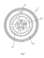
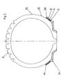
- Figures 1 and 2 show a wheel 1 having a rim 2 suitable for turning around an axis of rotation Z-Z and a 3engaged tire around this rim.
- This tire is of any type suitable for equipping a vehicle wheel.
- This tire is provided on each of its sidewalls 3A with a balancing device 4. There can of course be only one device balancing, on one side.
- This device 4 is here at a distance from the rim 2A of the rim on which the balancing weights are conventionally fixed; however it is preferably disposed radially between this rim and the part 3B of the tire which has a maximum width. This has the particular advantage of keeping the device balancing near the rim and ensuring that the centrifugal forces in service will be partly taken up by this bulged part 3B of the tire.
- This balancing device 4 essentially comprises a weight balancing 5 and a casing 6 in which the weight is enclosed and the constituent material has a color substantially identical to that of the material constituting the tire.
- This balancing weight 5 can be a conventional lead, as it is currently manufactured but without its fixing spring.
- envelope 6 it can be obtained by molding around the balancing weight; She is from preferably made of a material identical or similar to that of which the tire of the wheel is itself constituted, which is favorable for a good reciprocal connection between tire and casing; since this material has substantially the same color as the tire, the presence of the weight, enclosed in its envelope is barely visible.
- This small block 4 is fixed by at least one of its faces, treated for this purpose, on the sidewall of the tire, by example by collage.
- Block 4 thus fulfills its balancing function, remaining little visible and leaving the tire and rim intact if removed.
- the material of weight 5 is preferably lead classic (lead or lead alloy) but can also be another material such as steel, cast iron, zinc and aluminum alloy of the zamak type, alloy ferrous or non-ferrous, or even plastic (example polypropylene ).
- the envelope has a thickness which is preferably substantially constant (for example of the order of a millimeter) so that the shape of the weight appreciably determines that of the balancing device.
- the geometry of the weights 5 can be that of the current weights.
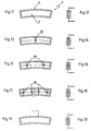
- the balancing device marked 14 internally runs along a rim 13A of the tire 13, disposed radially at the inside of the rim 12A of the rim 12; in this case the weight 15 has advantageously a convex face parallel to a convex surface 14A of the block along the tire, while the opposite face (figure 4) can be right (in fact, the geometry of this opposite face does not matter).
- each balancing device 24 is arranged radially outside a shoulder 23A of the tire 23, radially outside the rim 22A of the rim 22, the weight 25 has advantageously a concave surface parallel to a concave surface 24A of the block intended to follow the convex shape of the shoulder of the tire;
- the geometry of the opposite face of the weight can be arbitrary, for example convex or flat, in particular.
- the installation of the balancing device is made in an available area of the tire, without it having been necessarily designed to receive balancing devices according to the invention.
- the balancing device 34 (in FIGS. 7 and 8) or 44 (in Figures 9 and 10) is engaged in a clearance 33A or 43A of the pneumatic 33 or 43 provided for this purpose, here radially outside the rim free 32A or 42A of the rim 32 or 42.
- the device 34 is a portion of bead engaged in whole or in part in a circumferential groove 33A of the tire 33 and the envelope surrounding the balancing weight 35 is an arcuate part (FIG. 8) which has at least one strongly curved face 34A ( Figure 7), at least approximately in the portion of a cylinder (here substantially a half-cylinder) intended to follow the internal surface of the groove 33A.
- the device 44 is an arcuate part received in a clearance 43A of the tire 43 defining a groove with the rim 42A of the rim; the balancing device 44 does not occupy the entire section of this groove, remaining at a distance from this edge 42A.
- the envelope 46 surrounding the weight 45 a an arcuate shape with a convex face 44A intended to extend internally the shoulder presented by the tire opposite the rim 42A (as in the case of FIGS. 3 and 4, the radially internal portion of the weight can be any, concave or flat, in particular.
- a balancing device can be provided on the internal and / or external side of the wheel, depending on where the tire was fitted for this purpose.
- each of the aforementioned balancing devices can be made of various materials, in practice of the plastic type or polymer or a rubbery material; it is for example a material EPDM type, but it can also be PVC.
- This envelope can be flexible or rigid, depending on the material chosen.
- This envelope is made around weight, for example by overmolding. The realization of the whole envelope around the weight results in the weight being made integral with the envelope rubber so as to form a block.
- the color of the material of the envelope is chosen identical to that of the tire (black, white, green %) in order to make the block almost invisible once it is installed on the tire; it is necessary note that the skilled person knows without difficulty coloring the materials plastics or rubbery materials that can be used for the envelope.
- the shape and transverse dimensions in a plane of the wheel
- the differences in weight are obtained by differences in thickness (parallel to the axis of rotation).
- the balancing procedure begins with the choice of a weight capable of compensating for the unbalance observed on the wheel in question ( devices exist for this purpose for conventional weights and can easily be arranged according to the distance to the axis to which it is planned to fix the balancing devices on the tire).
- the surface of the envelope which is intended to be secured to the tire is advantageously treated accordingly.
- This treatment can simply consisted in giving it the desired geometry: it is in practice of simple geometry so as to follow the complementary shape of the pneumatic.
- this surface is advantageously bordered by sharp edges defining edges 80; it prevents the formation of slots between the block and the tire which could build up crack initiators which can then propagate in the surface for securing the block to the tire.
- slices of the block can be tapered or shaped like lips in order to follow the extension the surface of the tire (this is for example obtained by giving the block a trapezoidal section whose large base is intended to run along the surface tire).
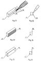
- Figures 21 and 22 show a block or balancing device 4 according to the invention being glued with glue 85 just before gluing against the corresponding surface of a tire.
- the block 4 In the variant shown in Figures 23 and 24 the block 4 'is pre-glued during its manufacture and, when wishes to secure it to a tire, we release a possible film of protection to release the layer of highly adhesive glue 90.
- Figures 25 and 26 describe another variant where the gluing of the fixing surface of the block 4 "consisted of putting a ribbon 95, for example coated on both sides a heat-activated adhesive; after release of a possible film of protection just reactivate the adhesive.
- the adhesive layer 90 or the tape 95 can be put in place at the last moment.
- the block thus glued (according to any one of the variants presented in connection with FIGS. 21 to 26) is then positioned on the pneumatic at the desired location, with a pressurization of a few seconds. The balancing procedure is then complete.
- the weight and therefore the balancing block have a generally parallelepiped shape possibly arched, except in the case of FIGS. 7 and 8.
- the attachment to the pneumatic can be done, depending on the case, on one side ( Figures 2 to 4), on two faces ( Figures 5, 6, 9 and 10) or a surface with a large curvature in a plane containing the axis of rotation ( Figures 7 and 8), which can be a surface semi-cylindrical (possibly arched to follow the circumference of the pneumatic).
- the balancing devices according to the invention are suitable perfectly with existing tires and can easily adapt to the tires currently under development and which are the subject new ways of fixing on the rim (example: pneumatic vertical hanging).
Landscapes
- Engineering & Computer Science (AREA)
- General Engineering & Computer Science (AREA)
- Mechanical Engineering (AREA)
- Physics & Mathematics (AREA)
- Acoustics & Sound (AREA)
- Aviation & Aerospace Engineering (AREA)
- Testing Of Balance (AREA)
- Tires In General (AREA)
- Turbine Rotor Nozzle Sealing (AREA)
- Constituent Portions Of Griding Lathes, Driving, Sensing And Control (AREA)
Applications Claiming Priority (3)
| Application Number | Priority Date | Filing Date | Title |
|---|---|---|---|
| FR9712528A FR2769349B1 (fr) | 1997-10-03 | 1997-10-03 | Perfectionnement aux systemes d'equilibrage de roues |
| FR9712528 | 1997-10-03 | ||
| PCT/FR1998/002112 WO1999018363A1 (fr) | 1997-10-03 | 1998-10-02 | Dispositif d'equilibrage pour roue et roue equipee d'un tel dispositif d'equilibrage |
Publications (2)
| Publication Number | Publication Date |
|---|---|
| EP1019643A1 EP1019643A1 (fr) | 2000-07-19 |
| EP1019643B1 true EP1019643B1 (fr) | 2003-01-08 |
Family
ID=9511953
Family Applications (1)
| Application Number | Title | Priority Date | Filing Date |
|---|---|---|---|
| EP98946551A Expired - Lifetime EP1019643B1 (fr) | 1997-10-03 | 1998-10-02 | Dispositif d'equilibrage pour roue et roue equipee d'un tel dispositif d'equilibrage |
Country Status (12)
| Country | Link |
|---|---|
| EP (1) | EP1019643B1 (tr) |
| JP (1) | JP2001519278A (tr) |
| AT (1) | ATE230831T1 (tr) |
| AU (1) | AU9355798A (tr) |
| BR (1) | BR9812610A (tr) |
| CA (1) | CA2306401A1 (tr) |
| DE (1) | DE69810646T2 (tr) |
| ES (1) | ES2189246T3 (tr) |
| FR (1) | FR2769349B1 (tr) |
| RO (1) | RO119565B1 (tr) |
| TR (1) | TR200000836T2 (tr) |
| WO (1) | WO1999018363A1 (tr) |
Families Citing this family (4)
| Publication number | Priority date | Publication date | Assignee | Title |
|---|---|---|---|---|
| JP3460814B2 (ja) | 2000-04-12 | 2003-10-27 | 広二郎 中村 | バランス・ウエイト |
| DE20012590U1 (de) | 2000-07-18 | 2000-10-19 | Franken Industrie Werke Ernst Stenz GmbH & Co. KG, 97080 Würzburg | Auswuchtgewicht |
| EP1318326A1 (de) * | 2001-12-06 | 2003-06-11 | Uwe Bettchen | Wuchtgewichtstrang zum Auswuchten von Fahrzeugrädern |
| DE102005005221A1 (de) * | 2005-02-03 | 2006-08-10 | Continental Aktiengesellschaft | Fahrzeugreifen |
Family Cites Families (8)
| Publication number | Priority date | Publication date | Assignee | Title |
|---|---|---|---|---|
| US1692145A (en) * | 1926-01-21 | 1928-11-20 | Chrysler Corp | Means for balancing pneumatic tires |
| US2245355A (en) * | 1938-05-23 | 1941-06-10 | Thomas W Mullen | Tire balancing |
| FR1151191A (fr) * | 1956-06-04 | 1958-01-24 | Dispositif pour l'équilibrage de roues de véhicules automobiles | |
| BE569954A (tr) * | 1957-10-10 | |||
| US3786850A (en) * | 1970-12-12 | 1974-01-22 | A Turoczi | Balanced tire |
| US4068898A (en) * | 1976-01-22 | 1978-01-17 | Hanson Donald E | Wheel-balancing weight having recording surface |
| JPS58152612A (ja) * | 1982-03-03 | 1983-09-10 | Sumitomo Rubber Ind Ltd | タイヤの重量バランス修正用部材 |
| SE453435B (sv) * | 1986-05-26 | 1988-02-01 | Candaco Ab | Forfarande for balansering av fordonsdeck, balanserat fordonsdeck samt for sadan balansering avsett fordonsdeck |
-
1997
- 1997-10-03 FR FR9712528A patent/FR2769349B1/fr not_active Expired - Fee Related
-
1998
- 1998-10-02 JP JP2000515123A patent/JP2001519278A/ja active Pending
- 1998-10-02 BR BR9812610-5A patent/BR9812610A/pt active Search and Examination
- 1998-10-02 RO ROA200000349A patent/RO119565B1/ro unknown
- 1998-10-02 AT AT98946551T patent/ATE230831T1/de not_active IP Right Cessation
- 1998-10-02 WO PCT/FR1998/002112 patent/WO1999018363A1/fr not_active Ceased
- 1998-10-02 EP EP98946551A patent/EP1019643B1/fr not_active Expired - Lifetime
- 1998-10-02 TR TR2000/00836T patent/TR200000836T2/tr unknown
- 1998-10-02 DE DE69810646T patent/DE69810646T2/de not_active Expired - Fee Related
- 1998-10-02 AU AU93557/98A patent/AU9355798A/en not_active Abandoned
- 1998-10-02 CA CA002306401A patent/CA2306401A1/fr not_active Abandoned
- 1998-10-02 ES ES98946551T patent/ES2189246T3/es not_active Expired - Lifetime
Also Published As
| Publication number | Publication date |
|---|---|
| DE69810646D1 (de) | 2003-02-13 |
| FR2769349B1 (fr) | 2002-04-05 |
| BR9812610A (pt) | 2000-08-01 |
| FR2769349A1 (fr) | 1999-04-09 |
| RO119565B1 (ro) | 2004-12-30 |
| CA2306401A1 (fr) | 1999-04-15 |
| TR200000836T2 (tr) | 2001-01-22 |
| ES2189246T3 (es) | 2003-07-01 |
| EP1019643A1 (fr) | 2000-07-19 |
| WO1999018363A1 (fr) | 1999-04-15 |
| JP2001519278A (ja) | 2001-10-23 |
| ATE230831T1 (de) | 2003-01-15 |
| DE69810646T2 (de) | 2003-10-30 |
| AU9355798A (en) | 1999-04-27 |
Similar Documents
| Publication | Publication Date | Title |
|---|---|---|
| EP1015261B1 (fr) | Sculpture et moule pour bande de roulement de pneumatique | |
| EP2318219B1 (fr) | Bande de roulement de pneu a sculpture directionnelle | |
| EP2512830B1 (fr) | Pneu a performance de roulage amelioree | |
| FR2492492A1 (fr) | Procede et dispositif d'insonorisation d'une roue metallique | |
| EP4222000A1 (fr) | Pneumatique comprenant un insert de flanc | |
| EP1165328B1 (fr) | Dispositif d'equilibrage pour roue et roue equilibree par collage d'un tel dispositif d'equilibrage | |
| EP1019643B1 (fr) | Dispositif d'equilibrage pour roue et roue equipee d'un tel dispositif d'equilibrage | |
| FR2516189A1 (fr) | Dispositif hydraulique d'actionnement pour un frein | |
| EP1420966B1 (fr) | Ensemble monte tubeless pour cycle | |
| EP1345783B1 (fr) | Ensemble consitute d'un pneumatique et d'une piece d'etancheite et procede de fabrication | |
| EP1194305B1 (fr) | Procede de demontage d'un pneumatique sur jante a sieges inclines vers l'exterieur | |
| EP0968848B1 (fr) | Bande de roulement de pneumatique comportant des incisions delimitant des plots de gomme | |
| EP0226967A1 (fr) | Dispositif de securité pour roulage de secours | |
| EP0155210A2 (fr) | Chambres à air discontinues | |
| EP1532006B1 (fr) | Ensemble monte tubeless pour cycle, jante et pneumatique tubeless | |
| EP1261498B1 (fr) | Jante avec sieges inclines vers l'exterieur et ensembles comprenant une telle jante et un appui de soutien gonfle | |
| FR2557661A1 (fr) | Poulie de variateur de vitesse a commande centrifuge | |
| FR2829969A1 (fr) | Jante de bicyclette et pneu prevus pour un montage de la roue sans chambre a air | |
| EP1160069B1 (fr) | Moule de pneumatique et procédé favorisant l'éventation d'un moule de pneumatique | |
| FR2669276A1 (fr) | Pneu pour velo de montagne ou tout-terrain. | |
| EP0192939A1 (fr) | Flap pour pneumatiques | |
| WO2026017433A1 (fr) | Pneumatique comprenant un insert de flanc à accrochage discontinu | |
| EP1538007B1 (fr) | Dispositif de roulage à plat pour véhicule automobile et ensemble monté l'incorporant | |
| EP1612063B1 (fr) | Dispositif de démontage d'un pneumatique sur jante à sièges inclines vers l'extérieur | |
| WO2026077727A1 (fr) | Pneumatique |
Legal Events
| Date | Code | Title | Description |
|---|---|---|---|
| PUAI | Public reference made under article 153(3) epc to a published international application that has entered the european phase |
Free format text: ORIGINAL CODE: 0009012 |
|
| 17P | Request for examination filed |
Effective date: 20000425 |
|
| AK | Designated contracting states |
Kind code of ref document: A1 Designated state(s): AT BE CH CY DE DK ES FI FR GB GR IE IT LI LU MC NL PT SE |
|
| 17Q | First examination report despatched |
Effective date: 20001103 |
|
| GRAG | Despatch of communication of intention to grant |
Free format text: ORIGINAL CODE: EPIDOS AGRA |
|
| GRAG | Despatch of communication of intention to grant |
Free format text: ORIGINAL CODE: EPIDOS AGRA |
|
| GRAH | Despatch of communication of intention to grant a patent |
Free format text: ORIGINAL CODE: EPIDOS IGRA |
|
| GRAH | Despatch of communication of intention to grant a patent |
Free format text: ORIGINAL CODE: EPIDOS IGRA |
|
| GRAA | (expected) grant |
Free format text: ORIGINAL CODE: 0009210 |
|
| AK | Designated contracting states |
Kind code of ref document: B1 Designated state(s): AT BE CH CY DE DK ES FI FR GB GR IE IT LI LU MC NL PT SE |
|
| PG25 | Lapsed in a contracting state [announced via postgrant information from national office to epo] |
Ref country code: NL Free format text: LAPSE BECAUSE OF FAILURE TO SUBMIT A TRANSLATION OF THE DESCRIPTION OR TO PAY THE FEE WITHIN THE PRESCRIBED TIME-LIMIT Effective date: 20030108 Ref country code: IE Free format text: LAPSE BECAUSE OF FAILURE TO SUBMIT A TRANSLATION OF THE DESCRIPTION OR TO PAY THE FEE WITHIN THE PRESCRIBED TIME-LIMIT Effective date: 20030108 Ref country code: GR Free format text: LAPSE BECAUSE OF FAILURE TO SUBMIT A TRANSLATION OF THE DESCRIPTION OR TO PAY THE FEE WITHIN THE PRESCRIBED TIME-LIMIT Effective date: 20030108 Ref country code: FI Free format text: LAPSE BECAUSE OF FAILURE TO SUBMIT A TRANSLATION OF THE DESCRIPTION OR TO PAY THE FEE WITHIN THE PRESCRIBED TIME-LIMIT Effective date: 20030108 Ref country code: AT Free format text: LAPSE BECAUSE OF FAILURE TO SUBMIT A TRANSLATION OF THE DESCRIPTION OR TO PAY THE FEE WITHIN THE PRESCRIBED TIME-LIMIT Effective date: 20030108 |
|
| REF | Corresponds to: |
Ref document number: 230831 Country of ref document: AT Date of ref document: 20030115 Kind code of ref document: T |
|
| REG | Reference to a national code |
Ref country code: GB Ref legal event code: FG4D Free format text: NOT ENGLISH |
|
| REG | Reference to a national code |
Ref country code: CH Ref legal event code: EP |
|
| REG | Reference to a national code |
Ref country code: IE Ref legal event code: FG4D Free format text: FRENCH |
|
| REF | Corresponds to: |
Ref document number: 69810646 Country of ref document: DE Date of ref document: 20030213 Kind code of ref document: P |
|
| PG25 | Lapsed in a contracting state [announced via postgrant information from national office to epo] |
Ref country code: SE Free format text: LAPSE BECAUSE OF FAILURE TO SUBMIT A TRANSLATION OF THE DESCRIPTION OR TO PAY THE FEE WITHIN THE PRESCRIBED TIME-LIMIT Effective date: 20030408 Ref country code: PT Free format text: LAPSE BECAUSE OF FAILURE TO SUBMIT A TRANSLATION OF THE DESCRIPTION OR TO PAY THE FEE WITHIN THE PRESCRIBED TIME-LIMIT Effective date: 20030408 Ref country code: DK Free format text: LAPSE BECAUSE OF FAILURE TO SUBMIT A TRANSLATION OF THE DESCRIPTION OR TO PAY THE FEE WITHIN THE PRESCRIBED TIME-LIMIT Effective date: 20030408 |
|
| GBT | Gb: translation of ep patent filed (gb section 77(6)(a)/1977) |
Effective date: 20030314 |
|
| REG | Reference to a national code |
Ref country code: ES Ref legal event code: FG2A Ref document number: 2189246 Country of ref document: ES Kind code of ref document: T3 |
|
| REG | Reference to a national code |
Ref country code: IE Ref legal event code: FD4D Ref document number: 1019643E Country of ref document: IE |
|
| PGFP | Annual fee paid to national office [announced via postgrant information from national office to epo] |
Ref country code: GB Payment date: 20030926 Year of fee payment: 6 |
|
| PG25 | Lapsed in a contracting state [announced via postgrant information from national office to epo] |
Ref country code: LU Free format text: LAPSE BECAUSE OF NON-PAYMENT OF DUE FEES Effective date: 20031002 Ref country code: CY Free format text: LAPSE BECAUSE OF FAILURE TO SUBMIT A TRANSLATION OF THE DESCRIPTION OR TO PAY THE FEE WITHIN THE PRESCRIBED TIME-LIMIT Effective date: 20031002 |
|
| PGFP | Annual fee paid to national office [announced via postgrant information from national office to epo] |
Ref country code: DE Payment date: 20031008 Year of fee payment: 6 |
|
| PGFP | Annual fee paid to national office [announced via postgrant information from national office to epo] |
Ref country code: ES Payment date: 20031014 Year of fee payment: 6 |
|
| PGFP | Annual fee paid to national office [announced via postgrant information from national office to epo] |
Ref country code: FR Payment date: 20031030 Year of fee payment: 6 |
|
| PG25 | Lapsed in a contracting state [announced via postgrant information from national office to epo] |
Ref country code: MC Free format text: LAPSE BECAUSE OF NON-PAYMENT OF DUE FEES Effective date: 20031031 Ref country code: LI Free format text: LAPSE BECAUSE OF NON-PAYMENT OF DUE FEES Effective date: 20031031 Ref country code: CH Free format text: LAPSE BECAUSE OF NON-PAYMENT OF DUE FEES Effective date: 20031031 Ref country code: BE Free format text: LAPSE BECAUSE OF NON-PAYMENT OF DUE FEES Effective date: 20031031 |
|
| PLBE | No opposition filed within time limit |
Free format text: ORIGINAL CODE: 0009261 |
|
| STAA | Information on the status of an ep patent application or granted ep patent |
Free format text: STATUS: NO OPPOSITION FILED WITHIN TIME LIMIT |
|
| 26N | No opposition filed |
Effective date: 20031009 |
|
| BERE | Be: lapsed |
Owner name: *FONDERIE DE GENTILLY Effective date: 20031031 |
|
| REG | Reference to a national code |
Ref country code: CH Ref legal event code: PL |
|
| PG25 | Lapsed in a contracting state [announced via postgrant information from national office to epo] |
Ref country code: GB Free format text: LAPSE BECAUSE OF NON-PAYMENT OF DUE FEES Effective date: 20041002 |
|
| PG25 | Lapsed in a contracting state [announced via postgrant information from national office to epo] |
Ref country code: ES Free format text: LAPSE BECAUSE OF NON-PAYMENT OF DUE FEES Effective date: 20041004 |
|
| PG25 | Lapsed in a contracting state [announced via postgrant information from national office to epo] |
Ref country code: DE Free format text: LAPSE BECAUSE OF NON-PAYMENT OF DUE FEES Effective date: 20050503 |
|
| GBPC | Gb: european patent ceased through non-payment of renewal fee |
Effective date: 20041002 |
|
| PG25 | Lapsed in a contracting state [announced via postgrant information from national office to epo] |
Ref country code: FR Free format text: LAPSE BECAUSE OF NON-PAYMENT OF DUE FEES Effective date: 20050630 |
|
| REG | Reference to a national code |
Ref country code: FR Ref legal event code: ST |
|
| PG25 | Lapsed in a contracting state [announced via postgrant information from national office to epo] |
Ref country code: IT Free format text: LAPSE BECAUSE OF NON-PAYMENT OF DUE FEES Effective date: 20051002 |
|
| REG | Reference to a national code |
Ref country code: ES Ref legal event code: FD2A Effective date: 20041004 |