EP1018532B1 - Process for making multifunctional plasma polymerized layers on plastic parts - Google Patents
Process for making multifunctional plasma polymerized layers on plastic parts Download PDFInfo
- Publication number
- EP1018532B1 EP1018532B1 EP19980122375 EP98122375A EP1018532B1 EP 1018532 B1 EP1018532 B1 EP 1018532B1 EP 19980122375 EP19980122375 EP 19980122375 EP 98122375 A EP98122375 A EP 98122375A EP 1018532 B1 EP1018532 B1 EP 1018532B1
- Authority
- EP
- European Patent Office
- Prior art keywords
- plasma
- plastic part
- layer
- plastic
- process according
- Prior art date
- Legal status (The legal status is an assumption and is not a legal conclusion. Google has not performed a legal analysis and makes no representation as to the accuracy of the status listed.)
- Expired - Lifetime
Links
Images


Classifications
-
- C—CHEMISTRY; METALLURGY
- C08—ORGANIC MACROMOLECULAR COMPOUNDS; THEIR PREPARATION OR CHEMICAL WORKING-UP; COMPOSITIONS BASED THEREON
- C08J—WORKING-UP; GENERAL PROCESSES OF COMPOUNDING; AFTER-TREATMENT NOT COVERED BY SUBCLASSES C08B, C08C, C08F, C08G or C08H
- C08J7/00—Chemical treatment or coating of shaped articles made of macromolecular substances
- C08J7/12—Chemical modification
- C08J7/123—Treatment by wave energy or particle radiation
-
- B—PERFORMING OPERATIONS; TRANSPORTING
- B05—SPRAYING OR ATOMISING IN GENERAL; APPLYING FLUENT MATERIALS TO SURFACES, IN GENERAL
- B05D—PROCESSES FOR APPLYING FLUENT MATERIALS TO SURFACES, IN GENERAL
- B05D1/00—Processes for applying liquids or other fluent materials
- B05D1/62—Plasma-deposition of organic layers
-
- B—PERFORMING OPERATIONS; TRANSPORTING
- B05—SPRAYING OR ATOMISING IN GENERAL; APPLYING FLUENT MATERIALS TO SURFACES, IN GENERAL
- B05D—PROCESSES FOR APPLYING FLUENT MATERIALS TO SURFACES, IN GENERAL
- B05D7/00—Processes, other than flocking, specially adapted for applying liquids or other fluent materials to particular surfaces or for applying particular liquids or other fluent materials
- B05D7/22—Processes, other than flocking, specially adapted for applying liquids or other fluent materials to particular surfaces or for applying particular liquids or other fluent materials to internal surfaces, e.g. of tubes
- B05D7/227—Processes, other than flocking, specially adapted for applying liquids or other fluent materials to particular surfaces or for applying particular liquids or other fluent materials to internal surfaces, e.g. of tubes of containers, cans or the like
-
- C—CHEMISTRY; METALLURGY
- C08—ORGANIC MACROMOLECULAR COMPOUNDS; THEIR PREPARATION OR CHEMICAL WORKING-UP; COMPOSITIONS BASED THEREON
- C08J—WORKING-UP; GENERAL PROCESSES OF COMPOUNDING; AFTER-TREATMENT NOT COVERED BY SUBCLASSES C08B, C08C, C08F, C08G or C08H
- C08J2323/00—Characterised by the use of homopolymers or copolymers of unsaturated aliphatic hydrocarbons having only one carbon-to-carbon double bond; Derivatives of such polymers
- C08J2323/02—Characterised by the use of homopolymers or copolymers of unsaturated aliphatic hydrocarbons having only one carbon-to-carbon double bond; Derivatives of such polymers not modified by chemical after treatment
- C08J2323/04—Homopolymers or copolymers of ethene
- C08J2323/06—Polyethene
Definitions
- the invention relates to a method for plasma-assisted production of multi-functional plasma-polymerized layers on defined refined inner surfaces of plastic parts such as plastic fuel containers (KKB) made of polyethylene.
- the production of KKB in the six-layer coextrusion process is known.
- the different coefficients of thermal expansion of the materials used in the six-layer coextrusion lead to very complicated cooling conditions, which in turn can lead to a further accumulation of defects on the inner wall KKB. Therefore, the coextruded KKB has already proven to be an innermost layer of an additional fine layer of PE-HD.
- the plasma polymerization is known to consist of various partially competing or in a static equilibrium reactions. In a rough classification, these can be subdivided into layer-building and layer-degrading reactions. Considering the model ideas for the layer-building reactions of interest, a pathway from monomer to layer through intermediates such as fragment, oligomer, and cluster is described ( Grünwald, Heinrich: Fundamentals and process technology of plasma polymerization; Lecture at the Plasmatec (1994 )). Another way described is the immediate adsorption of the monomer on the surface of the starting material (to be coated substrate) with a subsequent crosslinking by the - always present in the plasma process - hard UV radiation and electron bombardment.
- the invention has for its object to provide a method of the type mentioned above, with which the plasma polymerization on defined refined inner surfaces of the plastic parts such as plastic fuel tank (KKB) can be achieved, which should be set permeationsmindernd process optimized. In particular, care should be taken to optimize the plasma polymerization by defined pretreatment of the interior surfaces to be coated.
- the inner surfaces of the plastic part prior to barrier layering are formed by contamination with liquid media such as e.g. Hydrocarbon B (gasolines) pretreated.
- liquid media such as e.g. Hydrocarbon B (gasolines) pretreated.
- the oligomer concentration in the plastic part can furthermore be increased and / or the postcrosslinkability of the PE-HD of the plastic part can be increased by admixing reactive additives or by increasing the reactive proportions of the polymer.
- plastic part the inner surface of which is specifically smoothed by a suitable choice of the process parameters during blow molding, melt rotation or two-layer bulk production.
- barrier-reducing additives in the inner layer of the plastic fuel container (KKB) during its production allows during the subsequent plasma polymerization of the KKB an improved barrier effect, but without deteriorating the mechanical and thermal properties of the KKB PE-HD in any way. Also, the addition of higher-value components per carbon atom in the molecule proves to be beneficial.
- the method according to the invention optimizes the pretreatment of the starting material (substrate) to be coated by bringing it into contact with special chemicals before the plasma treatment. These chemicals adsorb and / or absorb on or in the substrate, so that the latter shows a new property profile during the plasma treatment / plasma polymerization.
- Adsorbed molecules accelerate the polymerization process because they are immediately available on the substrate for reaction and are not first brought to the substrate by the monomer gas stream have to. Absorbed molecules are stimulated by the relatively far-reaching penetration depth of the crosslinking radiation also within the substrate for crosslinking. They thus form ideal starting points for the further growing shift. This optimizing pretreatment allows for two modes of polymerization.
- the substrate is pretreated, and then a reaction is induced with a plasma without an organic monomer.
- gases include inert gases such as argon or gases which can generate specific radicals such as oxygen, hydrogen or nitrogen.
- the pretreated substrate is finished as before with a coated plasma (with organic monomer). Both methods can be used to optimize plasma polymerization in terms of treatment time and property profiles.
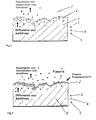
- Fig. 1 is a schematic representation of a greatly enlarged surface 2 of a KKB (substrate PE-HD) 1, illustrates that e.g. thermal energy induces the desorption of gas particles 3 and additives 4 into the vacuum space 5 from the substrate surface 2.
- Particles 6 and / or gas particles 3 stored or dissolved in the material of the substrate can be heated by thermal migration, i. get to the substrate surface 2 by diffusion.
- FIG. 2 illustrates the schematic barrier layer formation on the substrate PE-HD 1 according to a preferred embodiment of the method during the plasma treatment, wherein the layer formation consists proportionally of a combination of oligomers still present in the substrate , the KKB inner layer additionally supplied additives and the plasma polymerization process additionally supplied monomer / monomer gas mixtures takes place.
- Fig. 3 which shows the monomer / additive concentration as a function of the layer thickness of the substrate, shows that the monomer / additive concentration, starting from the maximum value on and immediately below the substrate surface 2, after a hyperbolic decrease at a certain Layer thickness of the substrate 1 remains constant.
- the release concentration of sorbed hydrocarbons in percent over the process time in minutes is plotted.
- the release concentration of the hydrocarbon decreases from 0.5% slightly, and then abruptly at the ignition point Z, and then decrease hyperbolaously.
- Fig. 6 is diagrammatically the layer structure in nanometers over the process time in minutes.
- the layer thickness decreases in a hyperbolic decreasing course during evacuation to remain constant in principle from ignition Z, in which case a favored by static charge particle occupancy and subsequent coverage of the Layer by means of plasma polymerization according to the curve P done.
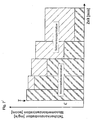
- FIG. 7 in which the particle concentration in mg / s "and the" monomer concentration in sccm “are each plotted as the actual flow rate of the corresponding materials over the" process time in min ", illustrates the process step in which nanoparticles and monomers are used for the It can be seen that after the plasma ignition (ignition time Z), the monomer concentration gradually decreases over time (dot-hatched columns) and combined increases the particle concentration in a stepwise step (dashed-line columns) the time is decreasing.
Landscapes
- Chemical & Material Sciences (AREA)
- Physics & Mathematics (AREA)
- Engineering & Computer Science (AREA)
- Plasma & Fusion (AREA)
- General Chemical & Material Sciences (AREA)
- Health & Medical Sciences (AREA)
- Chemical Kinetics & Catalysis (AREA)
- Medicinal Chemistry (AREA)
- Polymers & Plastics (AREA)
- Organic Chemistry (AREA)
- Treatments Of Macromolecular Shaped Articles (AREA)
Description
Die Erfindung betrifft ein Verfahren zur plasmagestützten Herstellung multifunktionaler plasmapolymerisierter Schichten auf definiert veredelten Innenoberflächen von Kunststoffteilen wie Kunststoffkraftstoffbehältern (KKB) aus Polyethylen.The invention relates to a method for plasma-assisted production of multi-functional plasma-polymerized layers on defined refined inner surfaces of plastic parts such as plastic fuel containers (KKB) made of polyethylene.
Es ist bekannt, daß die Morphologie der Innenoberfläche von blasgeformten und rußgefüllten Monolayer-Hohlkörpern aus Polyethylen hoher Dichte (PE-HD), insbesondere von Kunststoffkraftstoffbehältern (KKB), für Beschichtungen mittels Dünnschichttechnik keine optimale Substratoberfläche bilden. Hier wirkt sich vor allem die teilweise Entmischung der Rußpartikel zur Oberfläche hin sehr negativ aus, da damit verbunden unerwünschte Agglomerierungseffekte auftreten können, die zu einer sehr inhomogenen Oberfläche führen.It is known that the morphology of the inner surface of blow-molded and soot-filled monolayer hollow bodies made of high-density polyethylene (PE-HD), in particular plastic fuel containers (KKB), for thin-film coatings do not form an optimal substrate surface. Here, especially the partial separation of the soot particles to the surface has a very negative effect, as this can lead to undesirable agglomeration effects, which lead to a very inhomogeneous surface.
Weiterhin ist bekannt (
Alternativ zur Plasmapolymerisation ist die Herstellung von KKB im Sechsschicht-Coextrusionsverfahren bekannt. Die unterschiedlichen thermischen Ausdehnungskoeffizienten der bei der Sechsschicht-Coextrusion eingesetzten Werkstoffe führen jedoch zu sehr komplizierten Abkühlungsverhältnissen, die wiederum zu einer weiteren Anhäufung von Fehlstellen an der KKB-Innenwand führen können. Deshalb hat sich bereits beim coextrudierten KKB die Einbringung einer zusätzlichen Feinschicht aus PE-HD natur als innerste Schicht bewährt. Da diese Glättung der Innenoberfläche auch bei chemisch fluorierten KKB eine höhere Sperrwirkung ermöglicht, gibt es eine Tendenz zur Substitution der Einschichtextrusion (Monolayer) durch eine Zweischicht-Coextrusion mit einer Außenschicht aus rußversetztem PE-HD und einer inneren Schicht aus HD-PE natur, die als glatter, möglichst Fehlstellen freier Untergrund beste Voraussetzungen für die anschließend aufzubringende Barriereschicht liefert, ohne daß hierbei zwei unterschiedliche Werkstoffe verwendet werden. Die Zweischicht-Coextrusion wird bei der Herstellung unterschiedlichster Hohlkörper als Verpackungs- bzw. Vorratsbehälter in ökonomischer Weise eingesetzt.As an alternative to plasma polymerization, the production of KKB in the six-layer coextrusion process is known. The different coefficients of thermal expansion of the materials used in the six-layer coextrusion, however, lead to very complicated cooling conditions, which in turn can lead to a further accumulation of defects on the inner wall KKB. Therefore, the coextruded KKB has already proven to be an innermost layer of an additional fine layer of PE-HD. Since this smoothening of the inner surface, even with chemically fluorinated KKB a higher Blocking effect, there is a tendency to substitution of Einschichtextrusion (monolayer) by a two-layer coextrusion with an outer layer of soot-shifted PE-HD and an inner layer of HD-PE nature, which as smooth, possibly flaws free ground best conditions for the subsequent applied barrier layer provides, without this two different materials are used. The two-layer coextrusion is used in the production of a wide variety of hollow body as a packaging or storage container in an economical manner.
Die Plasmapolymerisation besteht bekanntermaßen aus verschiedenen teilweise konkurrierenden bzw. in einem statischen Gleichgewicht stehenden Reaktionen. In einer groben Einteilung lassen sich diese in schichtaufbauende und schichtabbauende Reaktionen unterteilen. Werden die Modellvorstellungen für die interessierenden schichtaufbauenden Reaktionen betrachtet, so ist ein Weg vom Monomer zur Schicht über Zwischenstationen wie Fragment, Oligomer und Cluster beschrieben (
Der Erfindung liegt die Aufgabe zugrunde, ein Verfahren der eingangs erwähnten Art zur Verfügung zu stellen, mit dem die Plasmapolymerisation auf definiert veredelten Innenoberflächen der Kunststoffteile wie Kunststoffkraftstoffbehälter (KKB) zu erzielen ist, die prozeßoptimiert permeationsmindernd eingestellt werden sollen. Insbesondere soll für eine Optimierung des Plasmapolymerisation durch definierte Vorbehandlung der zu beschichtenden Innenoberflächen gesorgt werden.The invention has for its object to provide a method of the type mentioned above, with which the plasma polymerization on defined refined inner surfaces of the plastic parts such as plastic fuel tank (KKB) can be achieved, which should be set permeationsmindernd process optimized. In particular, care should be taken to optimize the plasma polymerization by defined pretreatment of the interior surfaces to be coated.
Diese Aufgabe wird erfindungsgemäß gelöst durch ein Verfahren zur plasmagestützten Herstellung multifunktionaler plasmapolymerisierter Schichten auf definiert veredelten Innenoberflächen von Kunststoffteilen wie Kunststoffkraftstoffbehältern (KKB) aus Polyethylen, bei dem
- eine das Plasma bildende Prozeßgasatmosphäre erzeugt wird,
- die Innenoberfläche des Kunststoffteils unter Beaufschlagung mit dem Plasma beschichtet und parallel mit Nanoteilchen/Precusoren unter Nutzung der statischen Aufladung adsorptionsmäßig belegt wird,
- eine Barriereschicht in Form einer Nanoverbundschicht während einer Wasserstoff-, Sauerstoff-, Stickstoff- und/oder Inertgas-Plasmabehandlung anteilig aus einer Kombination der noch im Kunststoffteil vorhandenen Oligomere, gleichzeitig in die Innenoberfläche des Kunststoffteils zusätzlich eingeführter Additive sowie zeitgleich zugeführter Nanoteilchen und Monomeren/ Monomergasen gebildet wird, und
- gezielt Gase, Oligomere und/oder Monomere in die Outersurface (bis 5 nm Tiefe) und/oder Subsurface (bis 50 µm Tiefe) der Innenschicht des polymeren Kunststoffteils (KKB) temporär bis zum Einsetzen der Plasmabehandlung und der damit verbundenen Migration dieser Substanzen eingebunden werden.
- generating a plasma forming process gas atmosphere,
- the inner surface of the plastic part is coated under the action of plasma and adsorbed in parallel with nanoparticles / precursors using the static charge,
- a barrier layer in the form of a nanocomposite layer during a hydrogen, oxygen, nitrogen and / or inert gas plasma treatment proportionally from a combination of oligomers still present in the plastic part, at the same time in the inner surface of the plastic part additionally introduced additives and at the same time supplied nanoparticles and monomers / monomer gases is formed, and
- targeted gases, oligomers and / or monomers in the Outersurface (to 5 nm depth) and / or subsurface (up to 50 microns depth) of the inner layer of the polymeric plastic part (KKB) temporarily be included until the onset of plasma treatment and the associated migration of these substances ,
Vorteilhafte Weiterbildungen des erfindungsgemäßen Verfahrens sind in den Patentansprüchen 2 bis 5 beschrieben.Advantageous developments of the method according to the invention are described in the
Vorzugsweise wird die Innenoberflächen des Kunststoffteils vor der Barriereschichtbildung durch Kontamination mit flüssigen Medien wie z.B. Kohlenwasserstoffeb (Benzinen) vorbehandelt.Preferably, the inner surfaces of the plastic part prior to barrier layering are formed by contamination with liquid media such as e.g. Hydrocarbon B (gasolines) pretreated.
Zur Optimierung des Verfahrens kann weiterhin die Oligomerkonzentration im Kunststoffteil erhöht und/oder die Nachvernetzungsfähigkeit des PE-HD des Kunsststoffteils durch Zumischung reaktiver Additive oder durch Erhöhung der reaktiven Anteile des Polymers gesteigert werden.To optimize the process, the oligomer concentration in the plastic part can furthermore be increased and / or the postcrosslinkability of the PE-HD of the plastic part can be increased by admixing reactive additives or by increasing the reactive proportions of the polymer.
Von Vorteil ist es auch, ein Kunststoffteil zu verwenden, dessen Innenoberfläche durch geeignete Wahl der Verfahrensparameter beim Blasformen, der Schmelzrotation oder der Zweischicht-Bulk-Herstellung gezielt geglättet wird.It is also advantageous to use a plastic part, the inner surface of which is specifically smoothed by a suitable choice of the process parameters during blow molding, melt rotation or two-layer bulk production.
Die Zumischung barrierereduzierender Additive in die Innenschicht des Kunststoffkraftstoffbehälters (KKB) bei dessen Herstellung ermöglicht während der anschließenden Plasmapolymerisation des KKB eine verbesserte Barrierewirkung, ohne jedoch die mechanischen und thermischen Eigenschaften des KKB aus PE-HD in irgendeiner Weise zu verschlechtern. Auch die Hinzufügung von höherwertigen Stoffkomponenten pro Kohlenstoffatom im Molekül erweist sich als günstig.The admixture of barrier-reducing additives in the inner layer of the plastic fuel container (KKB) during its production allows during the subsequent plasma polymerization of the KKB an improved barrier effect, but without deteriorating the mechanical and thermal properties of the KKB PE-HD in any way. Also, the addition of higher-value components per carbon atom in the molecule proves to be beneficial.
Es ist bekannt (Dr. Andres Holländer, Dr. Jörg Behnisch, Vortrag "Zur Rolle der UV-Strahlung bei der Plasmabehandlung von Polymeren" auf der Frühjahrssitzung des Arbeitskreises Plasmaoberflächentechnologie am 12. Mai 1998), daß für Plasmaprozesse zwischen Outer Surface (bis 5 nm Tiefe) und Subsurface (bis 50 µm Tiefe) an der Oberfläche des polymeren Substrats unterschieden werden muß. Gemäß dem erfindungsgemäßen Verfahren werden daher Gase, Oligomere und/oder Monomere in die Outersurface (bis 5 nm Tiefe) und/oder Subsurface (bis 50 µm Tiefe) der Innenschicht des polymeren Kunststoffteils (KKB) temporär bis zum Einsetzen der Plasmabehandlung und der damit verbundenen Migration dieser Substanzen eingebunden. Von Wichtigkeit ist, daß diese Substanzen während des Evakuierens nicht aus dem Material der Innenschicht des KKB herausgesaugt werden. Dies kann durch geeignete Bindungskräfte oder genügende Eindringtiefe erreicht werden und ist auch über die vakuumtechnischen Parameter beeinflußbar und beherrschbar.It is known (Dr. Andres Holländer, Dr. Jörg Behnisch, lecture "On the role of UV radiation in the plasma treatment of polymers" at the spring meeting of the working group plasma surface technology on May 12, 1998) that plasma processes between Outer Surface (up to 5 nm depth) and subsurface (to 50 μm depth) at the surface of the polymeric substrate must be distinguished. According to the method of the invention, therefore, gases, oligomers and / or monomers in the Outersurface (to 5 nm depth) and / or Subsurface (to 50 microns depth) of the inner layer of the polymeric plastic part (KKB) temporarily until the onset of the plasma treatment and the associated Migration of these substances involved. Of importance is that these substances are not sucked out of the material of the inner layer of the KKB during evacuation. This can be achieved by suitable binding forces or sufficient penetration depth and can also be influenced and controlled via the vacuum-technical parameters.
Das erfindungsgemäße Verfahren sorgt für eine optimierende Vorbehandlung des zu beschichtenden Ausgangsmaterials (Substrats), indem dieses vor der Plasmabehandlung mit speziellen Chemikalien in Berührung gebracht wird. Diese Chemikalien ad- und/oder absorbieren an bzw. in dem Substrat, so daß letzteres ein neues Eigenschaftsprofil während der Plasmabehandlung/Plasmapolymerisation zeigt. Adsorbierte Moleküle beschleunigen den Polymerisationsprozeß, da sie sofort auf dem Substrat für eine Reaktion zur Verfügung stehen und nicht erst durch den Monomergasstrom an das Substrat herangeführt werden müssen. Absorbierte Moleküle werden durch die relativ weitreichende Eindringtiefe der Vernetzungsstrahlung auch innerhalb des Substrats zur Vernetzung angeregt. Sie bilden somit ideale Anknüpfungspunkte für die weiter aufwachsende Schicht. Diese optimierende Vorbehandlung ermöglicht zwei Arbeitsweisen für eine Polymerisation. Einserseits wird das Substrat vorbehandelt und anschließend wird mit einem Plasma ohne organisches Monomer eine Reaktion hervorgerufen. Als verwendete Gase kommen Inertgase wie Argon in Betracht oder auch Gase, die spezifische Radikale erzeugen können wie z.B. Sauerstoff, Wasserstoff oder Stickstoff. Anderseits wird das vorbehandelte Substrat wie bisher mit einem beschichteten Plasma (mit organischem Monomer) veredelt. Mit beiden Methoden kann die Plasmapolymerisation in Bezug auf Behandlungszeit und bezüglich der Eigenschaftsprofile optimiert werden.The method according to the invention optimizes the pretreatment of the starting material (substrate) to be coated by bringing it into contact with special chemicals before the plasma treatment. These chemicals adsorb and / or absorb on or in the substrate, so that the latter shows a new property profile during the plasma treatment / plasma polymerization. Adsorbed molecules accelerate the polymerization process because they are immediately available on the substrate for reaction and are not first brought to the substrate by the monomer gas stream have to. Absorbed molecules are stimulated by the relatively far-reaching penetration depth of the crosslinking radiation also within the substrate for crosslinking. They thus form ideal starting points for the further growing shift. This optimizing pretreatment allows for two modes of polymerization. On the one hand, the substrate is pretreated, and then a reaction is induced with a plasma without an organic monomer. Suitable gases include inert gases such as argon or gases which can generate specific radicals such as oxygen, hydrogen or nitrogen. On the other hand, the pretreated substrate is finished as before with a coated plasma (with organic monomer). Both methods can be used to optimize plasma polymerization in terms of treatment time and property profiles.
Das erfindungsgemäße Verfahren wird nun anhand der Zeichnungen erläutert. In diesen sind:
- Fig. 1
- eine schematische Darstellung einer stark vergrößerten KKB-Oberfläche im Vakuum, wobei das Verhalten von Gasteilchen, Partikeln und Additiven im Substrat bzw. an der Substrat-Oberfläche verdeutlicht ist,
- Fig. 2
- eine schematische Darstellung einer Barriereschichtbildung während der Plasmabehandlung der Substrat-Oberfläche,
- Fig. 3
- ein Diagramm, das die Monomer/Additiv - Konzentration in Abhängigkeit von der Eindringtiefe bzw. Schichtdicke in bzw. auf der Substrat-Oberfläche zeigt,
- Fig. 4
- ein Diagramm, aus dem die prozentuale Gewichtszunahme des Bulk über die Sorptionszeit hervorgeht,
- Fig. 5
- ein Diagramm, das die prozentuale Abgabekonzentration sorbierter Kohlenwasserstoffe über die Prozeßzeit zeigt,
- Fig. 6
- ein Diagramm, das den Schichtaufbau über die Prozeßzeit verdeutlicht, und
- Fig. 7
- ein Diagramm, das die Teilchen- und die Monomerkonzentration über die Prozeßzeit verdeutlicht.
- Fig. 1
- a schematic representation of a greatly enlarged KKB surface in a vacuum, wherein the behavior of gas particles, particles and additives in the substrate or on the substrate surface is illustrated,
- Fig. 2
- a schematic representation of a barrier layer formation during the plasma treatment of the substrate surface,
- Fig. 3
- a diagram showing the monomer / additive concentration as a function of the penetration depth or layer thickness in or on the substrate surface,
- Fig. 4
- a graph showing the percentage weight gain of the bulk over the sorption time,
- Fig. 5
- a diagram showing the percent release concentration of sorbed hydrocarbons over the process time,
- Fig. 6
- a diagram illustrating the layer structure over the process time, and
- Fig. 7
- a diagram illustrating the particle and the monomer concentration over the process time.
Im Hochvakuumbereich spielt die Freisetzung von Gasteilchen von einer Oberfläche in den Vakuumraum - die sogenannte Desorption - bekannterweise eine zu beachtende Funktion. Fig. 1, die eine schematische Darstellung einer stark vergrößerten Oberfläche 2 eines KKB (Substrat PE-HD) 1 darstellt, verdeutlicht, daß z.B. durch thermische Energie die Desorption von Gasteilchen 3 und Additiven 4 in den Vakuumraum 5 aus der Substrat-Oberfläche 2 induziert wird. Im Material des Substrats gespeicherte bzw. gelöste Teilchen 6 bzw. Gasteilchen 3 können durch thermische Wanderbewegung, d.h. durch Diffusion an die Substrat-Oberfläche 2 gelangen. Die Teilschritte Diffusion und Desorption bilden zusammen die Gasabgabe des Substrats 1. Fig. 2 verdeutlicht die schematische Barriereschichtbildung auf dem Substrat PE-HD 1 gemäß einer bevorzugten Ausführungsform des Verfahrens während der Plasmabehandlung, wobei die Schichtbildung anteilig aus einer Kombination von noch im Substrat vorhandener Oligomere, der KKB-Innenschicht zusätzlich zugeführter Additive und dem Plasmapolymerisationsprozeß zusätzlich zugeführter Monomer/Monomergasgemische erfolgt.In the high-vacuum range, the release of gas particles from a surface into the vacuum space - the so-called desorption - is known to have a function to be observed. Fig. 1, which is a schematic representation of a greatly
Fig. 3, aus der die Monomer/Additiv-Konzentration in Abhängigkeitvon der Schichtdicke des Substrats hervorgeht, verdeutlicht, daß die Monomer/Additiv - Konzentration, ausgehend vom Höchstwert auf und unmittelbar unterhalb der Substrat-Oberfläche 2, nach hyperbelartig verlaufender Abnahme bei einer bestimmten Schichtdicke des Substrats 1 konstant bleibt.Fig. 3, which shows the monomer / additive concentration as a function of the layer thickness of the substrate, shows that the monomer / additive concentration, starting from the maximum value on and immediately below the
Aus dem Diagramm gemäß Fig.4 geht - säulenartig dargestellt - die prozentuale Gewichtszunahme des Bulk über die Sorptionszeit, gemessen in Stunden, hervor,wobei zu sehen ist, daß nach 6 Stunden der Sättigungszustand bei 0,5 % der Gewichtszunahme des Bulk erreicht ist.From the diagram according to FIG. 4, the percentage increase in weight of the bulk over the sorption time, measured in hours, is shown in columnar form, whereby it can be seen that after 6 hours the saturation state is reached at 0.5% of the weight increase of the bulk.
Im Diagramm nach Fig. 5 ist die Abgabekonzentration sorbierter Kohlenwasserstoffe in Prozent über die Prozeßzeit in Minuten aufgetragen. Während der Evakuierungsphase E verringert sich die Abgabekonzentration des Kohlenwasserstoffs ausgehend von 0,5 % geringfügig, um dann im Zündzeitpunkt Z zunächst schlagartig und darauf hyperbelartig verlaufend abzunehmen.In the diagram according to FIG. 5, the release concentration of sorbed hydrocarbons in percent over the process time in minutes is plotted. During the evacuation phase E, the release concentration of the hydrocarbon decreases from 0.5% slightly, and then abruptly at the ignition point Z, and then decrease hyperbolaously.
Aus Fig. 6 geht diagrammmäßig der Schichtaufbau in Nanometer über die Prozeßzeit in Minuten hervor. Ausgehend von einem Schichtaufbau von 400 bis 1000 nm zu Beginn der Evakuierungsphase E verringert sich die Schichtstärke in einem hyperbelartig abnehmenden Verlauf während der Evakuierung, um ab Zündzeitpunkt Z im Prinzip konstant zu bleiben, wobei dann eine durch statische Aufladung begünstigte Teilchenbelegung und eine nachfolgende Überdeckung der Schicht mittels Plasmapolymerisation gemäß der Kurve P erfolgen.From Fig. 6 is diagrammatically the layer structure in nanometers over the process time in minutes. Starting from a layer structure of 400 to 1000 nm at the beginning of the evacuation phase E, the layer thickness decreases in a hyperbolic decreasing course during evacuation to remain constant in principle from ignition Z, in which case a favored by static charge particle occupancy and subsequent coverage of the Layer by means of plasma polymerization according to the curve P done.
Das Diagramm nach Fig. 7, in dem die Teilchenkonzentration in mg/s" und die "Monomerkonzentration in sccm" jeweils aktuelle Strömungsmenge der entsprechenden Materialien darstellend über die "Prozeßzeit in min" aufgetragen sind, verdeutlicht den Verfahrensschritt, bei dem Nanoteilchen und Monomere zur Bildung des Nanoverbundes während der Plasmapolymerisation eingebracht werden. Es ist zu sehen, daß nach erfolgter Plasmazündung (Zündzeitpunkt Z) die Monomerkonzentration über die Zeit stufenförmig abnimmt (punktschraffierte Säulen) und kombiniert die Teilchenkonzentration zugleich kompensationsmäßig stufenförmig zunimmt (strichschraffierte Säulen), wobei die Gesamtkonzentration über die Zeit abnimmt.The diagram according to FIG. 7, in which the particle concentration in mg / s "and the" monomer concentration in sccm "are each plotted as the actual flow rate of the corresponding materials over the" process time in min ", illustrates the process step in which nanoparticles and monomers are used for the It can be seen that after the plasma ignition (ignition time Z), the monomer concentration gradually decreases over time (dot-hatched columns) and combined increases the particle concentration in a stepwise step (dashed-line columns) the time is decreasing.
Claims (5)
- Process for the plasma-supported production of multifunctional plasma polymerised layers on defined surface-finished inside surfaces of plastic parts such as plastic fuel tanks (PFT) of polyethylene, in which process- a process gas atmosphere forming the plasma is produced,- the surface of the plastic part is coated by being charged with the plasma and, in parallel, covered with nanoparticles/precursors by adsorption while utilising the static charge,- a barrier layer is formed in the form of a nanocomposite layer of oligomers still present in the plastic part during a hydrogen, oxygen, nitrogen and/or inert gas plasma treatment proportionally, of additives additionally introduced simultaneously into the inside surface of the plastic part and nanoparticles and monomers/monomer gases simultaneously supplied and- gases, oligomers and monomers are bonded into the outer surface up to a depth of 5 nm and/or the subsurface up to a depth of 50 µm of the inside layer of the polymeric plastic part (PFT) temporarily up to the onset of plasma treatment and the associated migration of these substances.
- Process according to claim 1 characterised in that the inside surface of the plastic part is pretreated before the formation of the barrier layer by contamination with liquid media.
- Process according to claim 2 characterised in that hydrocarbons (benzenes) are used as liquid media.
- Process according to claim 1 to 3 characterised in that the post-crosslinkability of the PE-HD of the plastic part is increased by admixing reactive additives or by increasing the reactive portions of the polymer.
- Process according to one of the preceding claims characterised in that higher valent substance components per carbon atom in the molecule or the fuel component are added to the inside layer of the plastic fuel tank (PFT).
Priority Applications (2)
| Application Number | Priority Date | Filing Date | Title |
|---|---|---|---|
| EP19980122375 EP1018532B1 (en) | 1998-11-26 | 1998-11-26 | Process for making multifunctional plasma polymerized layers on plastic parts |
| DE59814153T DE59814153D1 (en) | 1998-11-26 | 1998-11-26 | Process for producing multifunctional plasma-polymerized layers on plastic parts, in particular on the inner surface of plastic fuel containers (KKB) made of polyethylene |
Applications Claiming Priority (1)
| Application Number | Priority Date | Filing Date | Title |
|---|---|---|---|
| EP19980122375 EP1018532B1 (en) | 1998-11-26 | 1998-11-26 | Process for making multifunctional plasma polymerized layers on plastic parts |
Publications (3)
| Publication Number | Publication Date |
|---|---|
| EP1018532A2 EP1018532A2 (en) | 2000-07-12 |
| EP1018532A3 EP1018532A3 (en) | 2000-08-09 |
| EP1018532B1 true EP1018532B1 (en) | 2008-01-16 |
Family
ID=8233033
Family Applications (1)
| Application Number | Title | Priority Date | Filing Date |
|---|---|---|---|
| EP19980122375 Expired - Lifetime EP1018532B1 (en) | 1998-11-26 | 1998-11-26 | Process for making multifunctional plasma polymerized layers on plastic parts |
Country Status (2)
| Country | Link |
|---|---|
| EP (1) | EP1018532B1 (en) |
| DE (1) | DE59814153D1 (en) |
Families Citing this family (2)
| Publication number | Priority date | Publication date | Assignee | Title |
|---|---|---|---|---|
| EP1741826A1 (en) | 2005-07-08 | 2007-01-10 | Nederlandse Organisatie voor Toegepast-Natuuurwetenschappelijk Onderzoek TNO | Method for depositing a polymer layer containing nanomaterial on a substrate material and apparatus |
| RU2469261C1 (en) * | 2011-06-22 | 2012-12-10 | ФЕДЕРАЛЬНОЕ ГОСУДАРСТВЕННОЕ ВОЕННОЕ ОБРАЗОВАТЕЛЬНОЕ УЧРЕЖДЕНИЕ ВЫСШЕГО ПРОФЕССИОНАЛЬНОГО ОБРАЗОВАНИЯ "ВОЕННАЯ АКАДЕМИЯ ТЫЛА И ТРАНСПОРТА имени генерала армии Хрулева А.В." | Method for determining complex strain and stress state of structure under static loads and dynamic stress |
Family Cites Families (2)
| Publication number | Priority date | Publication date | Assignee | Title |
|---|---|---|---|---|
| DE3908418C2 (en) * | 1989-03-15 | 1999-06-02 | Buck Chem Tech Werke | Process for the internal coating of plastic containers and device for coating |
| EP0739655B1 (en) * | 1995-04-28 | 1999-03-31 | INPRO Innovationsgesellschaft für fortgeschrittene Produktionssysteme in der Fahrzeugindustrie mbH | Process for plasma coating a plastic object with multifunctional layers |
-
1998
- 1998-11-26 EP EP19980122375 patent/EP1018532B1/en not_active Expired - Lifetime
- 1998-11-26 DE DE59814153T patent/DE59814153D1/en not_active Expired - Lifetime
Also Published As
| Publication number | Publication date |
|---|---|
| DE59814153D1 (en) | 2008-03-06 |
| EP1018532A2 (en) | 2000-07-12 |
| EP1018532A3 (en) | 2000-08-09 |
Similar Documents
| Publication | Publication Date | Title |
|---|---|---|
| EP1388594B1 (en) | Composite material with smooth barrier layer and process for its production | |
| EP0705149B1 (en) | Method for producing a polymer coating inside hollow plastic articles | |
| EP1415018B1 (en) | Composite material made from a substrate material and a barrier layer material | |
| DE69705552T2 (en) | Plasma processing method | |
| DE19731181C2 (en) | Method and device for coating polymeric base materials with thin SiC layers | |
| WO2002088593A1 (en) | Gastight container | |
| DE60117804T2 (en) | BARRIER COATING | |
| EP0739655B1 (en) | Process for plasma coating a plastic object with multifunctional layers | |
| DE10258681A1 (en) | Process for applying alternating layers e.g. barrier layers onto a plastic bottle by chemical gas phase deposition comprises depositing an organic adhesion promoting layer on a substrate and applying an inorganic barrier layer | |
| EP1018532B1 (en) | Process for making multifunctional plasma polymerized layers on plastic parts | |
| DE4404690A1 (en) | Method of forming two-layer gas and vapour barrier | |
| EP1051266B1 (en) | Polar polymeric coating | |
| DE4318084A1 (en) | Process and device for producing a polymeric outer layer in plastic blow mouldings | |
| DE68907093T2 (en) | Process for the production of non-porous membrane layers. | |
| DE10258678A1 (en) | Process for applying alternating layers e.g. barrier layers onto a plastic bottle by chemical gas phase deposition comprises depositing an organic adhesion promoting layer on a substrate and applying an inorganic barrier layer | |
| EP1917139A1 (en) | Composite system, associated use and method for the oxygen-free packaging of items susceptible to oxidation | |
| EP3402910B1 (en) | Process for producing a thin layer of porous dlc, use of a pecvd plant and workpiece coated with porous dlc | |
| DE102011086399B4 (en) | Nanoscale surface structure to improve the adhesion and process for its preparation | |
| DE102004017241B4 (en) | Composite material and method for its production | |
| EP3854907A1 (en) | Composite with barrier function, its production and use | |
| WO2023165913A1 (en) | Coating technology for plastic containers | |
| EP4182739B1 (en) | Method for applying a protective coating material | |
| EP1715532B1 (en) | Process for the formation of polymeric electrically conductive films | |
| DE1809906C (en) | Process for vacuum evaporation of adhesive mixed layers of inorganic and organic substances on a substrate | |
| EP3342834B1 (en) | Method for coating a wood substrate with a silicon dioxide layer |
Legal Events
| Date | Code | Title | Description |
|---|---|---|---|
| PUAI | Public reference made under article 153(3) epc to a published international application that has entered the european phase |
Free format text: ORIGINAL CODE: 0009012 |
|
| PUAL | Search report despatched |
Free format text: ORIGINAL CODE: 0009013 |
|
| AK | Designated contracting states |
Kind code of ref document: A2 Designated state(s): AT BE CH CY DE DK ES FI FR GB GR IE IT LI LU MC NL PT SE |
|
| AX | Request for extension of the european patent |
Free format text: AL;LT;LV;MK;RO;SI |
|
| AK | Designated contracting states |
Kind code of ref document: A3 Designated state(s): AT BE CH CY DE DK ES FI FR GB GR IE IT LI LU MC NL PT SE |
|
| AX | Request for extension of the european patent |
Free format text: AL;LT;LV;MK;RO;SI |
|
| RIN1 | Information on inventor provided before grant (corrected) |
Inventor name: STEINHARDT, INGOLF Inventor name: KLARE, JUERGEN Inventor name: KEMPEN, THOMAS Inventor name: HOYER, OLAF Inventor name: GLEICH, HENNING |
|
| RIN1 | Information on inventor provided before grant (corrected) |
Inventor name: STEINHARDT, INGOLF Inventor name: KLARE, JUERGEN Inventor name: KEMPEN, THOMAS Inventor name: HOYER, OLAF Inventor name: GLEICH, HENNING |
|
| 17P | Request for examination filed |
Effective date: 20010104 |
|
| AKX | Designation fees paid |
Free format text: DE |
|
| 17Q | First examination report despatched |
Effective date: 20040507 |
|
| GRAP | Despatch of communication of intention to grant a patent |
Free format text: ORIGINAL CODE: EPIDOSNIGR1 |
|
| GRAS | Grant fee paid |
Free format text: ORIGINAL CODE: EPIDOSNIGR3 |
|
| GRAA | (expected) grant |
Free format text: ORIGINAL CODE: 0009210 |
|
| AK | Designated contracting states |
Kind code of ref document: B1 Designated state(s): DE |
|
| REF | Corresponds to: |
Ref document number: 59814153 Country of ref document: DE Date of ref document: 20080306 Kind code of ref document: P |
|
| PLBE | No opposition filed within time limit |
Free format text: ORIGINAL CODE: 0009261 |
|
| STAA | Information on the status of an ep patent application or granted ep patent |
Free format text: STATUS: NO OPPOSITION FILED WITHIN TIME LIMIT |
|
| 26N | No opposition filed |
Effective date: 20081017 |
|
| REG | Reference to a national code |
Ref country code: DE Ref legal event code: R082 Ref document number: 59814153 Country of ref document: DE |
|
| REG | Reference to a national code |
Ref country code: DE Ref legal event code: R081 Ref document number: 59814153 Country of ref document: DE Owner name: SANOFI-AVENTIS DEUTSCHLAND GMBH, DE Free format text: FORMER OWNER: INPRO INNOVATIONSGESELLSCHAFT FUER FORTGESCHRITTENE PRODUKTIONSSYSTEME IN DER FAHRZEUGINDUSTRIE MBH, 10587 BERLIN, DE Effective date: 20130807 |
|
| PGFP | Annual fee paid to national office [announced via postgrant information from national office to epo] |
Ref country code: DE Payment date: 20171121 Year of fee payment: 20 |
|
| REG | Reference to a national code |
Ref country code: DE Ref legal event code: R071 Ref document number: 59814153 Country of ref document: DE |