EP3402910B1 - Process for producing a thin layer of porous dlc, use of a pecvd plant and workpiece coated with porous dlc - Google Patents
Process for producing a thin layer of porous dlc, use of a pecvd plant and workpiece coated with porous dlc Download PDFInfo
- Publication number
- EP3402910B1 EP3402910B1 EP17708976.0A EP17708976A EP3402910B1 EP 3402910 B1 EP3402910 B1 EP 3402910B1 EP 17708976 A EP17708976 A EP 17708976A EP 3402910 B1 EP3402910 B1 EP 3402910B1
- Authority
- EP
- European Patent Office
- Prior art keywords
- dlc
- porous
- layer
- workpiece
- dlc layer
- Prior art date
- Legal status (The legal status is an assumption and is not a legal conclusion. Google has not performed a legal analysis and makes no representation as to the accuracy of the status listed.)
- Active
Links
- 238000000034 method Methods 0.000 title claims description 41
- 230000008569 process Effects 0.000 title description 24
- 239000007789 gas Substances 0.000 claims description 43
- 238000000151 deposition Methods 0.000 claims description 37
- 230000008021 deposition Effects 0.000 claims description 33
- 238000005530 etching Methods 0.000 claims description 33
- 238000000623 plasma-assisted chemical vapour deposition Methods 0.000 claims description 20
- 239000011148 porous material Substances 0.000 claims description 17
- OKTJSMMVPCPJKN-UHFFFAOYSA-N Carbon Chemical compound [C] OKTJSMMVPCPJKN-UHFFFAOYSA-N 0.000 claims description 9
- 229910052799 carbon Inorganic materials 0.000 claims description 9
- 239000002243 precursor Substances 0.000 claims description 7
- UQEAIHBTYFGYIE-UHFFFAOYSA-N hexamethyldisiloxane Chemical compound C[Si](C)(C)O[Si](C)(C)C UQEAIHBTYFGYIE-UHFFFAOYSA-N 0.000 claims description 6
- MYMOFIZGZYHOMD-UHFFFAOYSA-N Dioxygen Chemical compound O=O MYMOFIZGZYHOMD-UHFFFAOYSA-N 0.000 claims description 3
- YCKRFDGAMUMZLT-UHFFFAOYSA-N Fluorine atom Chemical compound [F] YCKRFDGAMUMZLT-UHFFFAOYSA-N 0.000 claims description 3
- QVGXLLKOCUKJST-UHFFFAOYSA-N atomic oxygen Chemical compound [O] QVGXLLKOCUKJST-UHFFFAOYSA-N 0.000 claims description 3
- 229910052731 fluorine Inorganic materials 0.000 claims description 3
- 239000011737 fluorine Substances 0.000 claims description 3
- 239000001301 oxygen Substances 0.000 claims description 3
- 229910052760 oxygen Inorganic materials 0.000 claims description 3
- 125000002023 trifluoromethyl group Chemical group FC(F)(F)* 0.000 claims description 3
- HSFWRNGVRCDJHI-UHFFFAOYSA-N Acetylene Chemical compound C#C HSFWRNGVRCDJHI-UHFFFAOYSA-N 0.000 claims description 2
- 239000010410 layer Substances 0.000 description 90
- 238000004519 manufacturing process Methods 0.000 description 11
- 238000000576 coating method Methods 0.000 description 9
- 239000000463 material Substances 0.000 description 8
- 238000005229 chemical vapour deposition Methods 0.000 description 7
- 238000005259 measurement Methods 0.000 description 6
- 239000000758 substrate Substances 0.000 description 6
- 229910001220 stainless steel Inorganic materials 0.000 description 5
- 238000005299 abrasion Methods 0.000 description 4
- 230000004888 barrier function Effects 0.000 description 4
- 239000011248 coating agent Substances 0.000 description 4
- 238000009792 diffusion process Methods 0.000 description 4
- 239000003814 drug Substances 0.000 description 4
- 239000000314 lubricant Substances 0.000 description 4
- 229920000642 polymer Polymers 0.000 description 4
- 239000010935 stainless steel Substances 0.000 description 4
- 229910001200 Ferrotitanium Inorganic materials 0.000 description 3
- RTAQQCXQSZGOHL-UHFFFAOYSA-N Titanium Chemical compound [Ti] RTAQQCXQSZGOHL-UHFFFAOYSA-N 0.000 description 3
- 239000012298 atmosphere Substances 0.000 description 3
- 230000008901 benefit Effects 0.000 description 3
- 239000007943 implant Substances 0.000 description 3
- 239000010936 titanium Substances 0.000 description 3
- XKRFYHLGVUSROY-UHFFFAOYSA-N Argon Chemical compound [Ar] XKRFYHLGVUSROY-UHFFFAOYSA-N 0.000 description 2
- 238000005452 bending Methods 0.000 description 2
- 238000006243 chemical reaction Methods 0.000 description 2
- 229940079593 drug Drugs 0.000 description 2
- 238000002474 experimental method Methods 0.000 description 2
- 238000010438 heat treatment Methods 0.000 description 2
- 239000002346 layers by function Substances 0.000 description 2
- 238000000386 microscopy Methods 0.000 description 2
- 229910052756 noble gas Inorganic materials 0.000 description 2
- 230000035699 permeability Effects 0.000 description 2
- 238000001878 scanning electron micrograph Methods 0.000 description 2
- 239000000126 substance Substances 0.000 description 2
- 229910000831 Steel Inorganic materials 0.000 description 1
- 239000000654 additive Substances 0.000 description 1
- 230000000996 additive effect Effects 0.000 description 1
- 239000000853 adhesive Substances 0.000 description 1
- 230000001070 adhesive effect Effects 0.000 description 1
- 229910003481 amorphous carbon Inorganic materials 0.000 description 1
- 229910052786 argon Inorganic materials 0.000 description 1
- 230000015572 biosynthetic process Effects 0.000 description 1
- 239000007767 bonding agent Substances 0.000 description 1
- 238000005234 chemical deposition Methods 0.000 description 1
- 238000004140 cleaning Methods 0.000 description 1
- 238000002485 combustion reaction Methods 0.000 description 1
- 239000000599 controlled substance Substances 0.000 description 1
- 230000001419 dependent effect Effects 0.000 description 1
- 229910003460 diamond Inorganic materials 0.000 description 1
- 239000010432 diamond Substances 0.000 description 1
- 238000009826 distribution Methods 0.000 description 1
- 238000012377 drug delivery Methods 0.000 description 1
- 230000005684 electric field Effects 0.000 description 1
- 238000005516 engineering process Methods 0.000 description 1
- 125000002534 ethynyl group Chemical group [H]C#C* 0.000 description 1
- 239000000446 fuel Substances 0.000 description 1
- 229910002804 graphite Inorganic materials 0.000 description 1
- 239000010439 graphite Substances 0.000 description 1
- 238000011065 in-situ storage Methods 0.000 description 1
- 230000003993 interaction Effects 0.000 description 1
- 150000002500 ions Chemical class 0.000 description 1
- 230000007774 longterm Effects 0.000 description 1
- 238000011089 mechanical engineering Methods 0.000 description 1
- 230000007246 mechanism Effects 0.000 description 1
- 239000012528 membrane Substances 0.000 description 1
- 229910052751 metal Inorganic materials 0.000 description 1
- 239000002184 metal Substances 0.000 description 1
- 229910021645 metal ion Inorganic materials 0.000 description 1
- 150000002739 metals Chemical class 0.000 description 1
- 239000000203 mixture Substances 0.000 description 1
- 239000002245 particle Substances 0.000 description 1
- 239000004033 plastic Substances 0.000 description 1
- 229920003023 plastic Polymers 0.000 description 1
- 238000002360 preparation method Methods 0.000 description 1
- 238000004886 process control Methods 0.000 description 1
- 230000009467 reduction Effects 0.000 description 1
- 230000001105 regulatory effect Effects 0.000 description 1
- 238000004626 scanning electron microscopy Methods 0.000 description 1
- 238000001338 self-assembly Methods 0.000 description 1
- 239000010959 steel Substances 0.000 description 1
Images


Classifications
-
- C—CHEMISTRY; METALLURGY
- C23—COATING METALLIC MATERIAL; COATING MATERIAL WITH METALLIC MATERIAL; CHEMICAL SURFACE TREATMENT; DIFFUSION TREATMENT OF METALLIC MATERIAL; COATING BY VACUUM EVAPORATION, BY SPUTTERING, BY ION IMPLANTATION OR BY CHEMICAL VAPOUR DEPOSITION, IN GENERAL; INHIBITING CORROSION OF METALLIC MATERIAL OR INCRUSTATION IN GENERAL
- C23C—COATING METALLIC MATERIAL; COATING MATERIAL WITH METALLIC MATERIAL; SURFACE TREATMENT OF METALLIC MATERIAL BY DIFFUSION INTO THE SURFACE, BY CHEMICAL CONVERSION OR SUBSTITUTION; COATING BY VACUUM EVAPORATION, BY SPUTTERING, BY ION IMPLANTATION OR BY CHEMICAL VAPOUR DEPOSITION, IN GENERAL
- C23C16/00—Chemical coating by decomposition of gaseous compounds, without leaving reaction products of surface material in the coating, i.e. chemical vapour deposition [CVD] processes
- C23C16/22—Chemical coating by decomposition of gaseous compounds, without leaving reaction products of surface material in the coating, i.e. chemical vapour deposition [CVD] processes characterised by the deposition of inorganic material, other than metallic material
- C23C16/26—Deposition of carbon only
-
- A—HUMAN NECESSITIES
- A61—MEDICAL OR VETERINARY SCIENCE; HYGIENE
- A61L—METHODS OR APPARATUS FOR STERILISING MATERIALS OR OBJECTS IN GENERAL; DISINFECTION, STERILISATION OR DEODORISATION OF AIR; CHEMICAL ASPECTS OF BANDAGES, DRESSINGS, ABSORBENT PADS OR SURGICAL ARTICLES; MATERIALS FOR BANDAGES, DRESSINGS, ABSORBENT PADS OR SURGICAL ARTICLES
- A61L31/00—Materials for other surgical articles, e.g. stents, stent-grafts, shunts, surgical drapes, guide wires, materials for adhesion prevention, occluding devices, surgical gloves, tissue fixation devices
- A61L31/08—Materials for coatings
- A61L31/082—Inorganic materials
- A61L31/084—Carbon; Graphite
-
- A—HUMAN NECESSITIES
- A61—MEDICAL OR VETERINARY SCIENCE; HYGIENE
- A61L—METHODS OR APPARATUS FOR STERILISING MATERIALS OR OBJECTS IN GENERAL; DISINFECTION, STERILISATION OR DEODORISATION OF AIR; CHEMICAL ASPECTS OF BANDAGES, DRESSINGS, ABSORBENT PADS OR SURGICAL ARTICLES; MATERIALS FOR BANDAGES, DRESSINGS, ABSORBENT PADS OR SURGICAL ARTICLES
- A61L31/00—Materials for other surgical articles, e.g. stents, stent-grafts, shunts, surgical drapes, guide wires, materials for adhesion prevention, occluding devices, surgical gloves, tissue fixation devices
- A61L31/14—Materials characterised by their function or physical properties, e.g. injectable or lubricating compositions, shape-memory materials, surface modified materials
- A61L31/146—Porous materials, e.g. foams or sponges
-
- C—CHEMISTRY; METALLURGY
- C23—COATING METALLIC MATERIAL; COATING MATERIAL WITH METALLIC MATERIAL; CHEMICAL SURFACE TREATMENT; DIFFUSION TREATMENT OF METALLIC MATERIAL; COATING BY VACUUM EVAPORATION, BY SPUTTERING, BY ION IMPLANTATION OR BY CHEMICAL VAPOUR DEPOSITION, IN GENERAL; INHIBITING CORROSION OF METALLIC MATERIAL OR INCRUSTATION IN GENERAL
- C23C—COATING METALLIC MATERIAL; COATING MATERIAL WITH METALLIC MATERIAL; SURFACE TREATMENT OF METALLIC MATERIAL BY DIFFUSION INTO THE SURFACE, BY CHEMICAL CONVERSION OR SUBSTITUTION; COATING BY VACUUM EVAPORATION, BY SPUTTERING, BY ION IMPLANTATION OR BY CHEMICAL VAPOUR DEPOSITION, IN GENERAL
- C23C16/00—Chemical coating by decomposition of gaseous compounds, without leaving reaction products of surface material in the coating, i.e. chemical vapour deposition [CVD] processes
- C23C16/02—Pretreatment of the material to be coated
- C23C16/0227—Pretreatment of the material to be coated by cleaning or etching
- C23C16/0236—Pretreatment of the material to be coated by cleaning or etching by etching with a reactive gas
-
- C—CHEMISTRY; METALLURGY
- C23—COATING METALLIC MATERIAL; COATING MATERIAL WITH METALLIC MATERIAL; CHEMICAL SURFACE TREATMENT; DIFFUSION TREATMENT OF METALLIC MATERIAL; COATING BY VACUUM EVAPORATION, BY SPUTTERING, BY ION IMPLANTATION OR BY CHEMICAL VAPOUR DEPOSITION, IN GENERAL; INHIBITING CORROSION OF METALLIC MATERIAL OR INCRUSTATION IN GENERAL
- C23C—COATING METALLIC MATERIAL; COATING MATERIAL WITH METALLIC MATERIAL; SURFACE TREATMENT OF METALLIC MATERIAL BY DIFFUSION INTO THE SURFACE, BY CHEMICAL CONVERSION OR SUBSTITUTION; COATING BY VACUUM EVAPORATION, BY SPUTTERING, BY ION IMPLANTATION OR BY CHEMICAL VAPOUR DEPOSITION, IN GENERAL
- C23C16/00—Chemical coating by decomposition of gaseous compounds, without leaving reaction products of surface material in the coating, i.e. chemical vapour deposition [CVD] processes
- C23C16/02—Pretreatment of the material to be coated
- C23C16/0227—Pretreatment of the material to be coated by cleaning or etching
- C23C16/0245—Pretreatment of the material to be coated by cleaning or etching by etching with a plasma
-
- C—CHEMISTRY; METALLURGY
- C23—COATING METALLIC MATERIAL; COATING MATERIAL WITH METALLIC MATERIAL; CHEMICAL SURFACE TREATMENT; DIFFUSION TREATMENT OF METALLIC MATERIAL; COATING BY VACUUM EVAPORATION, BY SPUTTERING, BY ION IMPLANTATION OR BY CHEMICAL VAPOUR DEPOSITION, IN GENERAL; INHIBITING CORROSION OF METALLIC MATERIAL OR INCRUSTATION IN GENERAL
- C23C—COATING METALLIC MATERIAL; COATING MATERIAL WITH METALLIC MATERIAL; SURFACE TREATMENT OF METALLIC MATERIAL BY DIFFUSION INTO THE SURFACE, BY CHEMICAL CONVERSION OR SUBSTITUTION; COATING BY VACUUM EVAPORATION, BY SPUTTERING, BY ION IMPLANTATION OR BY CHEMICAL VAPOUR DEPOSITION, IN GENERAL
- C23C16/00—Chemical coating by decomposition of gaseous compounds, without leaving reaction products of surface material in the coating, i.e. chemical vapour deposition [CVD] processes
- C23C16/44—Chemical coating by decomposition of gaseous compounds, without leaving reaction products of surface material in the coating, i.e. chemical vapour deposition [CVD] processes characterised by the method of coating
- C23C16/50—Chemical coating by decomposition of gaseous compounds, without leaving reaction products of surface material in the coating, i.e. chemical vapour deposition [CVD] processes characterised by the method of coating using electric discharges
- C23C16/505—Chemical coating by decomposition of gaseous compounds, without leaving reaction products of surface material in the coating, i.e. chemical vapour deposition [CVD] processes characterised by the method of coating using electric discharges using radio frequency discharges
-
- C—CHEMISTRY; METALLURGY
- C23—COATING METALLIC MATERIAL; COATING MATERIAL WITH METALLIC MATERIAL; CHEMICAL SURFACE TREATMENT; DIFFUSION TREATMENT OF METALLIC MATERIAL; COATING BY VACUUM EVAPORATION, BY SPUTTERING, BY ION IMPLANTATION OR BY CHEMICAL VAPOUR DEPOSITION, IN GENERAL; INHIBITING CORROSION OF METALLIC MATERIAL OR INCRUSTATION IN GENERAL
- C23C—COATING METALLIC MATERIAL; COATING MATERIAL WITH METALLIC MATERIAL; SURFACE TREATMENT OF METALLIC MATERIAL BY DIFFUSION INTO THE SURFACE, BY CHEMICAL CONVERSION OR SUBSTITUTION; COATING BY VACUUM EVAPORATION, BY SPUTTERING, BY ION IMPLANTATION OR BY CHEMICAL VAPOUR DEPOSITION, IN GENERAL
- C23C16/00—Chemical coating by decomposition of gaseous compounds, without leaving reaction products of surface material in the coating, i.e. chemical vapour deposition [CVD] processes
- C23C16/56—After-treatment
Definitions
- the invention relates to a method for producing a thin layer of porous diamond-like carbon (DLC) with plasma enhanced chemical vapor deposition (PECVD). Furthermore, the invention relates to the use of a PECVD system and a workpiece having a surface which is coated with a porous DLC layer.
- DLC diamond-like carbon
- PECVD plasma enhanced chemical vapor deposition
- Coatings made of carbon can be used to realize a variety of surface functions.
- Such functional layers are thin layers that consist predominantly of carbon.
- these are amorphous carbon layers which are produced in chemical vapor deposition (CVD) processes, ie by means of chemical vapor deposition.
- CVD chemical vapor deposition
- One form of carbon functional layers are DLC (diamond like carbon) layers.
- DLC has a high hardness and high wear resistance.
- DLC layers are used for example in the internal combustion engine.
- Moving parts such as the camshaft, piston rings, or even gears, are DLC coated to minimize wear and friction to make vehicles more durable, more powerful, and lower in emissions.
- DLC coatings are used as coatings on heating or fuel elements or, due to their good biocompatibility, as surface coatings on implants.
- CVD chemical vapor deposition
- PECVD plasma enhanced chemical vapor deposition
- the chemical deposition is supported by a plasma.
- the molecules of a reaction or precursor gas are dissociated (broken up) by the external supply of heat and by the released energy of the chemical reaction.
- this task is done by the accelerated electrons in the plasma.
- ions are generated in a plasma which, together with the radicals, cause the layer deposition on the substrate or workpiece.
- the gas temperature in the plasma only increases by a few 100 ° C., which means that PECVD, in contrast to CVD, can also be used to coat temperature-sensitive materials without difficulty.
- the plasma can burn directly at the substrate or workpiece to be coated or in a separate chamber (remote plasma method).
- a strong electric field is applied between the substrate to be coated and a counterelectrode, by which a plasma is ignited.
- a direct plasma has the advantage that an in-situ plasma substrate cleaning is performed can.
- PECVD DLC coatings are used as a diffusion barrier on implant materials to prevent metal ions from diffusing out.
- the coating is chemically inert, adhesive and wear resistant.
- a workpiece is known from a translucent substrate, which is provided with a coating of DLC.
- the DLC layer is made by deposition using PECVD using acetylene.
- the DLC layer is porous, the volume fraction of the pores is between 40% and 70%.
- US 2005/0260411 A1 is a hydrogen-free DLC film made by growing and etching back.
- the DLC layer is porous, the porosity is between 15% and 60%.
- Patent document US 5,939,149 discloses a DLC layer which is modified by an etchback process.
- the deposited on the surface of the workpiece DLC layer when prepared with the aforementioned process parameters, defined pores.
- a DLC layer is suitable as a diffusion membrane with defined permeability.
- it can serve as a barrier with defined and specifically adjustable diffusivity. It can be used, for example, for a defined long-term medication (controlled pharma release).
- the porous DLC layer is applied to a polymer layer which comprises a medicament. Such a layer system can be applied for example on the surface of an implant.
- the DLC layer is a biocompatible surface which simultaneously acts as a controlled and controllable diffusion barrier.
- the pores of a porous DLC layer may be provided with a lubricant reservoir. It is a friction and wear reduction achieved not only by the DLC layer itself, but also by the held lubricant.
- the porous DLC layer has all the characteristics and advantages known from conventional DLC layers.
- a deposition step alternately takes place, in which the DLC layer on the surface of the object to be coated with the mentioned process parameters is deposited, and a remind intimid in which the deposited on the surface of the workpiece DLC layer is etched back under said process parameters performed.
- the deposition step and the re-etching step are adjusted so that the overall positive growth rate is achieved. So it is deposited more material than etched back. It was recognized that in the re-etching step above all layer portions with an SP2 bond (graphite bond) are removed.
- the chosen process parameters result in a self-organized porous surface.
- the deposition step and the re-etching step are repeated several times. For example, between 2 and 25 repetitions, for example 5 repetitions, are performed.
- the porous DLC layer is the result of the deposition step and the subsequent re-etching step, ie both steps.
- the method is developed in that a deposition rate with which the DLC layer is deposited on the surface to be coated is greater than an etching back rate with which the DLC layer deposited on the surface is etched back.
- the deposition rate is larger by more than a factor of five, in particular by more than a factor of ten, in particular by more than a factor of 15, and furthermore in particular by at most a factor of 20 greater than the re-etching rate.
- the ratio of the deposited amount and the amount of replenishment which may also be in the ratio of the above-mentioned factors, is set, in addition to the rates, for example, by the duration of the respective steps. It is also provided that the deposition or rinserate by variation of Set process parameters of the deposition step or the gearmonskys.
- the aforementioned ratios or factors between deposition rate and re-etching rate or amount deposited and etched back amount have proven to be particularly advantageous for the production of a porous DLC layer.
- the deposition rate is between 100 nm / min and 160 nm / min and the re-etching rate is between 10 nm / min and 20 nm / min.
- a relaxation step is carried out between the depositing and etching-back step (s) in which the layer is subjected to a heat treatment.
- the layer is aged out or annealed in the relaxation step. It is also contemplated to perform a relaxation step after a certain number of successive deposition and etchback steps. This can be done once or several times during the preparation of the porous DLC layer respectively.
- the workpiece consists at least predominantly of titanium or stainless steel, at least predominantly on its surface to be coated.
- stainless steels of the type 316L or X5CRNI are provided.
- other materials are suitable for producing a layer of porous DLC deposited thereon, for example metals or even plastics.
- average pore sizes can preferably be produced between 3 ⁇ m and 20 ⁇ m.
- the deposited layers produced showed excellent adhesion and abrasion resistance. Their hardness was between 5 GPa and 10 GPa. These values are often measured with a nanoindenter. The adhesion and abrasion resistance was determined in bending tests on various samples.
- the prepared porous DLC layer was examined by scanning electron microscopy and confocal laser microscopy, particularly to determine the pore size and distribution.
- the relaxation step provision is made in particular for the layer to be relaxed at a temperature of less than 200 ° C. for a predetermined time interval of, in particular, between 15 minutes and 30 minutes.
- a predetermined time interval of, in particular, between 15 minutes and 30 minutes.
- the precursor gas in particular at least predominantly, consists of one of the following gases: C 2 H 2 , CH 4 or HMDSO (hexamethyldisiloxane).
- the re-etching gas is at least predominantly an oxygen-containing gas, in particular pure oxygen (O 2 ), and / or a fluorine-containing gas, in particular F 2 trifluoromethyl (CF 4 or CF 3 radicals).
- oxygen-containing gas in particular pure oxygen (O 2 )
- fluorine-containing gas in particular F 2 trifluoromethyl (CF 4 or CF 3 radicals).
- porous DLC layers having excellent adhesion, desired mechanical properties, for example, in terms of elastic modulus and surface tension, having desired porosity, biocompatibility, and chemical composition can be prepared.
- the object is further achieved by the use of a PECVD system for performing a method according to one or more of the aforementioned aspects.
- a workpiece according to claim 10 having a surface coated with a porous DLC layer produced in a method according to one or more of the aforementioned aspects.
- Fig. 1 shows in a simplified schematic view of a PECVD system 2, the recipient 4 is connected via a connecting flange 6 to a suitable pump unit 7.
- This pump unit 7 evacuates the interior of the recipient 4 to a base pressure of less than 10 -3 mbar.
- the pump unit 7 includes, for example, a combination on a rotary vane pump and a turbomolecular pump.
- a pressure sensor 9 is provided on a flange of the recipient 4.
- the pressure sensor comprises by way of example a plurality of pressure gauges or pressure gauges.
- a gas inlet 8 for example a ring provided with openings, via which process gas is introduced into the interior of the recipient 4.
- the gas inlet 8 is connected to a corresponding process gas supply 10.
- the process gases exemplified by C 2 H 2 as a precursor gas, O 2 as a recycle gas and Ar as a noble gas, are fed via a respective mass flow controller 11 (flow controller) to the interior of the recipient 4 via the gas inlet 8.
- a sample holder 12 is arranged in the interior of the recipient 2, which fulfills the function of a counter electrode. While the counter electrode is grounded, an RF electrode 13 is coupled to an AC power supply 14. On the sample holder 12 are the workpieces 16 to be coated, shown in simplified form as substrates. The workpieces 16 comprise one or more surfaces 20 to be coated. For reasons of clarity, only a few workpieces 16 and surfaces 20 are provided with reference symbols.
- a plasma 18 is generated in the interior of the recipient. From the gas atmosphere, a layer of diamond-like carbon (DLC) is thus deposited on a surface 20 of the workpieces 16 to be coated. It is not yet a porous DLC layer at this moment.
- DLC diamond-like carbon
- the AC power supply 14 is part of a control device 15, by which it can also be controlled or regulated for the purpose of process control.
- the control device 15 also serves to drive or read the pump unit 7, the pressure sensor 9 and the mass flow controller 11. In order to keep the working pressure in the recipient constant, the control device 15 also controls or regulates a valve 17 (butterfly valve) via the motor M.
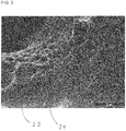
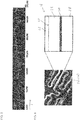
- Fig. 2 and 3 show scanning electron micrographs of a porous DLC layer 22, as they can be produced on a workpiece in the system shown. Clearly visible are the pores 24 of different sizes.
- the workpiece 16 is first placed in the recipient 4, which is then evacuated to the desired base pressure.
- the workpiece 16 is for example made of titanium or stainless steel, for example of type 316L or X5CRNI stainless steel.
- Process gas is then supplied to the recipient 4 via the mass flow controller 11.
- suitable process gases are, for example, C 2 H 2 , CH 4 or HMDSO (hexamethyldisiloxane).
- the process gas is supplied to the recipient 4, for example, at a flow rate of 5 sccm.
- a high-frequency AC voltage for example, applied with a frequency of 13.56 MHz.
- a BIAS (self-BIAS) voltage of, for example, -200 V is established, and a DLC layer is deposited on the surface 20 of the workpiece 16. This is done at a working pressure between 20 * 10 -3 mbar and 30 * 10 -3 mbar.
- the BIAS voltage is between -150 V and -250 V and is present between the RF electrode 13 and the grounded counter electrode (sample holding 12).
- the bias voltage can also be within the specified interval.
- the layer deposited on the surface 20 of the workpiece 16 is initially not yet a porous DLC layer.
- the porosity of the layer is only achieved by a part of the deposited DLC layer is removed again in a subsequent etching back and the deposition step and the remind intimid be repeated several times.
- the etching-back step takes place in that after at least predominantly removal of the process gas from the recipient 4 and termination of the plasma discharge, an etching-back gas is introduced into the recipient 4. This takes place again via the gas inlet 8 and a corresponding control by the mass flow controller 11.
- an oxygen-containing gas for example pure oxygen O 2
- a fluorine-containing gas for example F 2 or trifluoromethyl
- the re-etching gas is supplied to the recipient 4 at a flow rate of 90 sccm, for example.
- the etching back step takes place at a working pressure between 200 * 10 -3 mbar and 300 * 10 -3 mbar and a BIAS voltage between -330 V and -340 V, for example from -380 V.
- the bias voltage as well as the working pressure lie in the aforementioned interval.
- the SP2 portions of the deposited DLC layer are removed.
- This selective etching process could be identified as an important mechanism for the formation of the pores 24 in the porous DLC layer 22 in addition to self-organizing processes that also take place.
- a deposition step and an associated back-etching step then take place again. This process is repeated until the desired layer thickness of the porous DLC layer 22 on the surface 20 of the workpiece 16 is reached.
- a mixed atmosphere can be used, to which a noble gas component, for example argon, is added in addition to the process or re-etching gas.
- a noble gas component for example argon
- the DLC layer is deposited on the surface 20 to be coated at a deposition rate that is greater than an etching back rate at which the DLC particles deposited on the surface are deposited. Layer is etched back.
- the deposition rate or the amount deposited is many times greater than the re-etching rate or the amount repaid. Suitable factors are for example 3, 5, 7, 10, 13, 15, 17 and 20. Higher remindraten are not provided according to an embodiment. In other words, the deposition rate is thus maximum Twenty times the re-etching rate.
- the deposition rate between 100 nm / min and 160 nm / min in particular between 110 nm / min and 150 nm / min, more particularly between 120 nm / min and 140 nm / min.
- deposition rates of 100 nm / min, 110 nm / min, 120 nm / min, 130 nm / min, 140 nm / min or 150 nm / min are provided.
- the re-etching rate is between 10 nm / min and 20 nm / min, in particular between 12 nm / min and 18 nm / min, and in particular between 14 nm / min and 16 nm / min.
- back-etching rates of 10 nm / min, 12 nm / min, 14 nm / min, 16 nm / min, 18 nm / min or 20 nm / min are provided.
- the porous DLC layer 22 is formed at the specified process parameters by self-assembly processes on the surface to be coated 20. It has also been found to be advantageous if integrated into the production relaxation steps in which the porous DLC layer 22 is relaxed. In other words, therefore, the production of the porous DLC layer 22 is stopped for a short time and then continued from the intermediate "frozen" state. The entire production takes place, for example, at temperatures of less than 200 ° C. A suitable time interval for the relaxation step is between 15 minutes and 30 minutes. The relaxation step thus has a duration of, for example, 5, 10, 20, 25 or 30 minutes.
- the relaxation step may be between the deposition and the etchback step, with a relaxation step provided between each or only some of the deposition and etchback steps.
- Fig. 4 shows a measurement, which was carried out with confocal laser microscopy. Visible is a surface 20 of a porous DLC layer 22. Along the path S, a profile measurement of the surface morphology of the prepared porous DLC layer 22 has been performed. The result of such an exemplary measurement along the distance S shows Fig. 5 ,
- Fig. 5 the measuring section S is plotted on the abscissa and the height of the surface in arbitrary units on the ordinate.
- the pronounced minima of the profile indicate the pores 24 present in the porous DLC layer 22.
- an average pore size was determined which, for example, is between 3 ⁇ m and 20 ⁇ m. Bending and abrasion tests have also revealed that the porous DLC layer 22 exhibits excellent adhesion and high abrasion resistance.
- the hardness of the porous DLC layer 22 is between 5 and 10 GPa. These values were also determined with a nanoindenter.
- the pore size is very well controlled by the magnitude of the bias voltage.
- the average pore size scales at least approximately proportionally with the BIAS voltage.
- Fig. 6 shows in a simplified representation of a detail of a stent 26 as an example of a workpiece 16.
- the schematically illustrated detail and cross-sectional view through a web of the stent 26 in Fig. 6 shows that this has a special layer structure for a controlled drug delivery over a longer period of time.
- a primer 30 is first applied on a base material 28, such as titanium or stainless steel.
- a polymer layer 32 which is mixed with a drug.
- a porous DLC layer 22 On its surface is a porous DLC layer 22, which represents a diffusion barrier with defined diffusivity.
- the permeability of the porous DLC layer 22 is dependent, inter alia, on the average pore size of the pores 24 present in the porous DLC layer 22. It is thus possible to set the rate with which the medicament present in the polymer layer 32 is released into the environment via the porous DLC layer 22.
- Another embodiment is a workpiece 16 in the field of mechanical engineering, which is not shown. It has a similar structure to the one in Fig. 6 shown workpiece 16.
- a porous DLC layer 22 is applied directly. This DLC layer serves, for example, to reduce the friction.
- the workpiece may be a camshaft and the surface may be its control surface.
- the pores 24 of the porous DLC layer 20 may be provided with a friction reducing additive or lubricant.
- the DLC layer 22 acts to reduce friction by the continuously metered lubricant.
Description
Die Erfindung betrifft ein Verfahren zum Herstellen einer dünnen Schicht aus porösem diamantähnlichem Kohlenstoff (DLC) mit plasmaunterstützter chemischer Gasphasenabscheidung (PECVD). Ferner betrifft die Erfindung die Verwendung einer PECVD-Anlage sowie ein Werkstück mit einer Oberfläche, die mit einer porösen DLC-Schicht beschichtet ist.The invention relates to a method for producing a thin layer of porous diamond-like carbon (DLC) with plasma enhanced chemical vapor deposition (PECVD). Furthermore, the invention relates to the use of a PECVD system and a workpiece having a surface which is coated with a porous DLC layer.
Mit Beschichtungen aus Kohlenstoff lassen sich vielfältige Oberflächenfunktionen realisieren. Solche Funktionsschichten sind dünne Schichten, die überwiegend aus Kohlenstoff bestehen. Beispielsweise handelt es sich um amorphe Kohlenstoffschichten, die in CVD-Verfahren (engl. chemical vapor deposition), also mittels chemischer Gasphasenabscheidung, hergestellt sind. Eine Form von Kohlenstofffunktionsschichten sind DLC-Schichten (engl. diamond like carbon).Coatings made of carbon can be used to realize a variety of surface functions. Such functional layers are thin layers that consist predominantly of carbon. By way of example, these are amorphous carbon layers which are produced in chemical vapor deposition (CVD) processes, ie by means of chemical vapor deposition. One form of carbon functional layers are DLC (diamond like carbon) layers.
DLC weist eine große Härte und einen hohen Verschleißwiderstand auf. In der Kraftfahrzeugtechnik werden DLC-Schichten beispielsweise im Verbrennungsmotor eingesetzt. Bewegliche Teile, wie etwa die Nockenwelle, die Kolbenringe oder auch Zahnräder, werden mit DLC beschichtet, um Verschleiß und Reibung zu minimieren und so die Fahrzeuge haltbarer, leistungsstärker und emissionsärmer zu machen. Außerdem kommen DLC-Schichten als Beschichtung auf Heiz- oder Brennelementen oder aufgrund ihrer guten Biokompatibilität als Oberflächenbeschichtung auf Implantaten zum Einsatz.DLC has a high hardness and high wear resistance. In automotive engineering DLC layers are used for example in the internal combustion engine. Moving parts, such as the camshaft, piston rings, or even gears, are DLC coated to minimize wear and friction to make vehicles more durable, more powerful, and lower in emissions. In addition, DLC coatings are used as coatings on heating or fuel elements or, due to their good biocompatibility, as surface coatings on implants.
Eine Variante der chemischen Gasphasenabscheidung (CVD) ist die plasmaunterstützte chemische Gasphasenabscheidung (PECVD). Bei dieser wird die chemische Abscheidung durch ein Plasma unterstützt. Während der CVD erfolgt eine Dissoziation (Aufbrechen) der Moleküle eines Reaktions- oder Precursor-Gases durch externe Zufuhr von Wärme sowie durch die freiwerdende Energie der chemischen Reaktion. Bei der PECVD übernehmen diese Aufgabe die beschleunigten Elektronen im Plasma. Zusätzlich zu den so gebildeten Radikalen werden in einem Plasma Ionen erzeugt, die zusammen mit den Radikalen die Schichtabscheidung auf dem Substrat bzw. Werkstück bewirken. Die Gastemperatur im Plasma erhöht sich dabei in der Regel nur um wenige 100 °C, wodurch mit der PECVD im Gegensatz zur CVD auch temperaturempfindlichere Materialien problemlos beschichtet werden können.One variant of chemical vapor deposition (CVD) is plasma enhanced chemical vapor deposition (PECVD). In this case, the chemical deposition is supported by a plasma. During CVD, the molecules of a reaction or precursor gas are dissociated (broken up) by the external supply of heat and by the released energy of the chemical reaction. In the PECVD this task is done by the accelerated electrons in the plasma. In addition to the radicals thus formed, ions are generated in a plasma which, together with the radicals, cause the layer deposition on the substrate or workpiece. As a rule, the gas temperature in the plasma only increases by a few 100 ° C., which means that PECVD, in contrast to CVD, can also be used to coat temperature-sensitive materials without difficulty.
Das Plasma kann direkt beim zu beschichtenden Substrat oder Werkstück oder in einer eigenen Kammer (Remote-Plasma-Methode) brennen. Bei der zuerst genannten sogenannten Direktplasmamethode wird zwischen dem zu beschichtenden Substrat und einer Gegenelektrode ein starkes elektrisches Feld angelegt, durch das ein Plasma gezündet wird. Ein direktes Plasma hat den Vorteil, dass eine in-situ Plasmasubstratreinigung durchgeführt werden kann.The plasma can burn directly at the substrate or workpiece to be coated or in a separate chamber (remote plasma method). In the first-mentioned direct plasma method, a strong electric field is applied between the substrate to be coated and a counterelectrode, by which a plasma is ignited. A direct plasma has the advantage that an in-situ plasma substrate cleaning is performed can.
Mit PECVD hergestellte DLC-Beschichtungen werden als Diffusionsbarriere auf Implantatwerkstoffen eingesetzt, um ein Ausdiffundieren von Metallionen zu verhindern. Die Beschichtung ist chemisch inert, haft- und verschleißfest.PECVD DLC coatings are used as a diffusion barrier on implant materials to prevent metal ions from diffusing out. The coating is chemically inert, adhesive and wear resistant.
Aus
Aus
Patentdokument
Es ist eine Aufgabe der Erfindung, ein Verfahren zum Herstellen einer dünnen Schicht aus DLC, die Verwendung einer PECVD-Anlage sowie ein Werkstück mit einer mit DLC-beschichteten Oberfläche anzugeben, wobei die DLC-Schicht porös sein soll.It is an object of the invention to provide a method for producing a thin layer of DLC, the use of a PECVD system and a workpiece with a DLC-coated surface, wherein the DLC layer should be porous.
Die Aufgabe wird gelöst durch ein Verfahren zum Herstellen einer dünnen Schicht aus porösem diamantähnlichem Kohlenstoff (DLC) mit plasmaunterstützter chemischer Gasphasenabscheidung (PECVD) entsprechend Anspruch 1, bei dem ein zu beschichtendes Werkstück in einem Rezipienten bereitgestellt und anschließend auf einer zu beschichtenden Oberfläche des Werkstücks eine dünne Schicht aus porösem DLC durch Ausführen der folgenden Schritte deponiert wird:
- Einleiten eines kohlenstoffhaltigen Precursor-Gases in den Rezipienten und Abscheiden einer DLC-Schicht auf der zu beschichtenden Oberfläche des Werkstücks bei einem Arbeitsdruck von 20∗10-3 mbar bis 30∗10-3 mbar und einer BIAS-Spannung von
- 250 V bis -150 V,
- anschließendes Einleiten eines Rückätz-Gases in den Rezipienten und Rückätzen der auf der Oberfläche des Werkstücks deponierten DLC-Schicht bei einem Arbeitsdruck von 200∗10-3 mbar bis 300∗10-3 mbar und einer BIAS-Spannung von -430 V bis -330 V.
- Introducing a carbonaceous precursor gas into the recipient and depositing a DLC coating on the coating Surface of the workpiece at a working pressure of 20 * 10 -3 mbar to 30 * 10 -3 mbar and a bias voltage of
- 250V to -150V,
- then introducing a re-etching gas into the recipient and re-etching the deposited on the surface of the workpiece DLC layer at a working pressure of 200 * 10 -3 mbar to 300 * 10 -3 mbar and a BIAS voltage of -430 V to -330 V.
Vorteilhaft weist die auf der Oberfläche des Werkstücks abgeschiedene DLC-Schicht, wenn sie mit den zuvor genannten Prozessparametern hergestellt wird, definierte Poren auf. Im Gegensatz zu plasmaunterstützt hergestellten DLC-Schichten herkömmlicher Art, die keine Poren aufweisen, eröffnen sich für die DLC-Schichten gemäß Aspekten der Erfindung ganz neue Anwendungsgebiete. Beispielsweise kommt eine solche DLC-Schicht als Diffusionsmembran mit definierter Permeabilität infrage. In der Medizintechnik kann sie als eine Barriere mit definierter und gezielt einstellbarer Diffusivität dienen. Sie kann beispielsweise für eine definierte Dauermedikamentation (controlled pharma release) eingesetzt werden. Hierzu wird beispielsweise die poröse DLC-Schicht auf eine Polymerschicht, welche ein Medikament umfasst, aufgebracht. Ein solches Schichtsystem kann beispielsweise auf der Oberfläche eines Implantats aufgebracht werden. Die DLC-Schicht ist eine biokompatible Oberfläche, welche gleichzeitig als kontrollierte und kontrollierbare Diffusionsbarriere wirkt.Advantageously, the deposited on the surface of the workpiece DLC layer, when prepared with the aforementioned process parameters, defined pores. In contrast to Plasma-supported fabricated DLC layers of conventional type, which have no pores, opens up completely new fields of application for the DLC layers according to aspects of the invention. For example, such a DLC layer is suitable as a diffusion membrane with defined permeability. In medical technology, it can serve as a barrier with defined and specifically adjustable diffusivity. It can be used, for example, for a defined long-term medication (controlled pharma release). For this purpose, for example, the porous DLC layer is applied to a polymer layer which comprises a medicament. Such a layer system can be applied for example on the surface of an implant. The DLC layer is a biocompatible surface which simultaneously acts as a controlled and controllable diffusion barrier.
In einem vollkommen anderen technischen Gebiet, wie beispielsweise dem Maschinenbau oder der Kraftfahrzeugtechnik, können die Poren einer porösen DLC-Schicht mit einem Schmiermittelreservoir versehen werden. Es wird eine Reibungs- und Verschleißminderung nicht nur durch die DLC-Schicht selbst, sondern zusätzlich durch das vorgehaltene Schmiermittel erreicht.In a completely different technical field, such as engineering or automotive engineering, the pores of a porous DLC layer may be provided with a lubricant reservoir. It is a friction and wear reduction achieved not only by the DLC layer itself, but also by the held lubricant.
Die poröse DLC-Schicht weist gleichzeitig alle charakteristischen Eigenschaften und Vorteile auf, wie sie von herkömmlichen DLC-Schichten bekannt sind. Lediglich beispielshaft sei auf ihre gute Adhäsion auf einer Vielzahl von Werkstoffen, ihre große Härte und Verschleißfestigkeit sowie die Flexibilität des Herstellungsprozesses verwiesen.At the same time, the porous DLC layer has all the characteristics and advantages known from conventional DLC layers. By way of example, reference is made to their good adhesion to a variety of materials, their high hardness and wear resistance and the flexibility of the manufacturing process.
Bei der Herstellung der porösen DLC-Schicht werden alternierend ein Depositionsschritt, in dem die DLC-Schicht auf der zu beschichtenden Oberfläche des Objekts mit den genannten Prozessparametern abgeschieden wird, und ein Rückätzschritt, bei dem die auf der Oberfläche des Werkstücks deponierte DLC-Schicht unter den genannten Prozessparametern zurückgeätzt wird, durchgeführt. Der Depositionsschritt und der Rückätzschritt werden so eingestellt, dass in der Summe eine positive Aufwachsrate erzielt wird. Es wird also mehr Material deponiert als zurückgeätzt. Es wurde erkannt, dass bei dem Rückätzschritt vor allem Schichtanteile mit einer SP2-Bindung (Graphitbindung) abgetragen werden. Bei den gewählten Prozessparametern ergibt sich selbstorganisiert eine poröse Oberfläche.During the production of the porous DLC layer, a deposition step alternately takes place, in which the DLC layer on the surface of the object to be coated with the mentioned process parameters is deposited, and a Rückätzschritt in which the deposited on the surface of the workpiece DLC layer is etched back under said process parameters performed. The deposition step and the re-etching step are adjusted so that the overall positive growth rate is achieved. So it is deposited more material than etched back. It was recognized that in the re-etching step above all layer portions with an SP2 bond (graphite bond) are removed. The chosen process parameters result in a self-organized porous surface.
Der Depositionsschritt und der Rückätzschritt werden mehrfach wiederholt ausgeführt. Beispielsweise werden zwischen 2 und 25 Wiederholungen, beispielsweise 5 Wiederholungen, durchgeführt. Die poröse DLC-Schicht ist das Ergebnis des Depositionsschritts und des sich anschließenden Rückätzschritts, also beider Schritte.The deposition step and the re-etching step are repeated several times. For example, between 2 and 25 repetitions, for example 5 repetitions, are performed. The porous DLC layer is the result of the deposition step and the subsequent re-etching step, ie both steps.
Gemäß einer Ausführungsform ist das Verfahren dadurch fortgebildet, dass eine Depositionsrate, mit der die DLC-Schicht auf der zu beschichtenden Oberfläche deponiert wird, größer ist als eine Rückätzrate, mit der die auf der Oberfläche deponierte DLC-Schicht zurückgeätzt wird. Insbesondere ist vorgesehen, dass die Depositionsrate um mehr als einen Faktor fünf größer, insbesondere um mehr als einen Faktor zehn größer, insbesondere um mehr als einen Faktor 15 größer, und ferner insbesondere um höchstens einen Faktor 20 größer ist als die Rückätzrate.According to one embodiment, the method is developed in that a deposition rate with which the DLC layer is deposited on the surface to be coated is greater than an etching back rate with which the DLC layer deposited on the surface is etched back. In particular, it is provided that the deposition rate is larger by more than a factor of five, in particular by more than a factor of ten, in particular by more than a factor of 15, and furthermore in particular by at most a factor of 20 greater than the re-etching rate.
Das Verhältnis der deponierten Menge und der rückgeätzen Menge, welche ebenso im Verhältnis der o.g. Faktoren zueinander stehen können, wird außer durch die Raten ferner beispielsweise durch die zeitliche Dauer der entsprechenden Schritte eingestellt. Ebenso ist vorgesehen, die Depositions- bzw. Rückätzrate durch Variation der Prozessparameter des Depositionsschritts bzw. des Rückätzschritts einzustellen. Die zuvor genannten Verhältnisse bzw. Faktoren zwischen Depositionsrate und Rückätzrate bzw. deponierter Menge und rückgeätzer Menge haben sich zur Herstellung einer porösen DLC-Schicht als besonders vorteilhaft erwiesen.The ratio of the deposited amount and the amount of replenishment, which may also be in the ratio of the above-mentioned factors, is set, in addition to the rates, for example, by the duration of the respective steps. It is also provided that the deposition or Rückätzrate by variation of Set process parameters of the deposition step or the Rückätzschritts. The aforementioned ratios or factors between deposition rate and re-etching rate or amount deposited and etched back amount have proven to be particularly advantageous for the production of a porous DLC layer.
Ferner ist insbesondere vorgesehen, dass die Depositionsrate zwischen 100 nm/min und 160 nm/min liegt und die Rückätzrate zwischen 10 nm/min und 20 nm/min liegt.In addition, it is provided in particular that the deposition rate is between 100 nm / min and 160 nm / min and the re-etching rate is between 10 nm / min and 20 nm / min.
Ebenso wie sich die zuvor genannten Verhältnisse zwischen der Depositionsrate und der Rückätzrate als vorteilhaft herausgestellt haben, haben sich auch die zuvor genannten absoluten Werte der Depositionsrate bzw. Rückätzrate in praktischen Versuchen als sehr geeignet erwiesen.Just as the above-mentioned relationships between the deposition rate and the re-etching rate have proven to be advantageous, the abovementioned absolute values of the deposition rate and the re-etching rate have also proven to be very suitable in practical experiments.
Gemäß einer weiteren Ausführungsform ist ferner vorgesehen, dass zwischen dem oder den Depositions- und Rückätzschritt(en) ein Relaxationsschritt durchgeführt wird, bei dem die Schicht einer Wärmebehandlung unterzogen wird.According to a further embodiment it is further provided that a relaxation step is carried out between the depositing and etching-back step (s) in which the layer is subjected to a heat treatment.
Es ist ebenso vorgesehen, den Relaxationsschritt nicht zwischen dem Depositionsschritt und dem Rückätzschritt bzw. zwischen den Depositionsschritten und den Rückätzschritten durchzuführen, sondern die hergestellte poröse DLC-Schicht am Ende ihrer Herstellung einer Wärmebehandlung zu unterziehen.It is also envisaged not to perform the relaxation step between the deposition step and the etch-back step or between the deposition steps and the etch-back steps, but to heat-treat the produced porous DLC layer at the end of its manufacture.
Mit anderen Worten wird die Schicht im Relaxationsschritt ausgelagert bzw. angelassen. Es ist ebenso vorgesehen, einen Relaxationsschritt nach einer gewissen Anzahl von aufeinanderfolgenden Depositions- und Rückätzschritten durchzuführen. Dies kann einmal oder mehrfach während der Herstellung der porösen DLC-Schicht erfolgen.In other words, the layer is aged out or annealed in the relaxation step. It is also contemplated to perform a relaxation step after a certain number of successive deposition and etchback steps. This can be done once or several times during the preparation of the porous DLC layer respectively.
Das Werkstück besteht zumindest an seiner zu beschichtenden Oberfläche zumindest überwiegend bevorzugt aus Titan oder Edelstahl. Insbesondere sind Edelstähle des Typs 316L oder X5CRNI vorgesehen. Ebenso sind weitere Materialien zur Herstellung einer darauf abgeschiedenen Schicht aus porösem DLC geeignet, beispielsweise Metalle oder auch Kunststoffe.The workpiece consists at least predominantly of titanium or stainless steel, at least predominantly on its surface to be coated. In particular, stainless steels of the type 316L or X5CRNI are provided. Likewise, other materials are suitable for producing a layer of porous DLC deposited thereon, for example metals or even plastics.
Mit den genannten Prozessparametern lassen sich mittlere Porengrößen bevorzugt zwischen 3 µm und 20 µm erzeugen. Die hergestellten deponierten Schichten zeigten eine exzellente Adhäsion und Abriebfestigkeit. Ihre Härte lag zwischen 5 GPa und 10 GPa. Diese Werte werden vielfach mit einem Nanoindenter gemessen. Die Adhäsion und Abriebfestigkeit wurde in Biegetests an verschiedenen Proben ermittelt. Außerdem wurde die hergestellte poröse DLC-Schicht mit Rasterelektronenmikroskop bzw. Transmissionselektronenmikroskopie sowie mit konfokaler Lasermikroskopie untersucht, insbesondere um die Porengröße und -verteilung zu bestimmen.With the process parameters mentioned, average pore sizes can preferably be produced between 3 μm and 20 μm. The deposited layers produced showed excellent adhesion and abrasion resistance. Their hardness was between 5 GPa and 10 GPa. These values are often measured with a nanoindenter. The adhesion and abrasion resistance was determined in bending tests on various samples. In addition, the prepared porous DLC layer was examined by scanning electron microscopy and confocal laser microscopy, particularly to determine the pore size and distribution.
Für den Relaxationsschritt ist insbesondere vorgesehen, dass die Schicht bei einer Temperatur von weniger als 200°C für ein vorgegebenes Zeitintervall von insbesondere zwischen 15 min und 30 min relaxiert wird. Mit anderen Worten wird der Prozess, in welchem sich Deposition und Rückätzen stetig abwechseln, für eine bestimmte Zeitspanne unterbrochen. Der aktuell erreichte Zustand wird auf diese Weise gewissermaßen "eingefroren". Wenn die Herstellung anschließend fortgesetzt wird, geschieht dies mit anderer/veränderter Ausgangslage, so dass die Relaxationsschritte das erreichte Ergebnis, also die hergestellte poröse DLC-Schicht beeinflussen.For the relaxation step, provision is made in particular for the layer to be relaxed at a temperature of less than 200 ° C. for a predetermined time interval of, in particular, between 15 minutes and 30 minutes. In other words, the process in which deposition and backflash alternate constantly is interrupted for a certain period of time. The currently achieved state is in a sense "frozen" in this way. If the production is then continued, this is done with a different / changed initial position, so that the relaxation steps affect the result achieved, that is, the produced porous DLC layer.
Gemäß einer weiteren Ausführungsform ist vorgesehen, dass das Precursor-Gas, insbesondere zumindest überwiegend, aus einem der folgenden Gase besteht: C2H2, CH4 oder HMDSO (Hexamethyldisiloxan).According to a further embodiment, it is provided that the precursor gas, in particular at least predominantly, consists of one of the following gases: C 2 H 2 , CH 4 or HMDSO (hexamethyldisiloxane).
Ferner hat es sich als vorteilhaft herausgestellt, wenn das Rückätz-Gas zumindest überwiegend ein sauerstoffhaltiges Gas, insbesondere reiner Sauerstoff (O2), und/oder ein fluorhaltiges Gas, insbesondere F2 Trifluormethyl (CF4 oder CF3-Radikale) ist.Furthermore, it has proven to be advantageous if the re-etching gas is at least predominantly an oxygen-containing gas, in particular pure oxygen (O 2 ), and / or a fluorine-containing gas, in particular F 2 trifluoromethyl (CF 4 or CF 3 radicals).
Auch die zuvor genannten Substanzen, welche als Precursor-Gas bzw. Rückätzgas zur Anwendung kommen, haben sich in praktischen Versuchen als besonders vorteilhaft erwiesen. Zusammenfassend können in dem Verfahren gemäß Aspekten der Erfindung poröse DLC-Schichten mit hervorragender Haftung, den gewünschten mechanischen Eigenschaften, beispielsweise im Hinblick auf das Elastizitätsmodul und Oberflächenspannung, mit gewünschter Porosität, Biokompatibilität und chemischer Zusammensetzung herstellt werden.The abovementioned substances which are used as precursor gas or re-etching gas have also proven to be particularly advantageous in practical experiments. In summary, in the method according to aspects of the invention, porous DLC layers having excellent adhesion, desired mechanical properties, for example, in terms of elastic modulus and surface tension, having desired porosity, biocompatibility, and chemical composition can be prepared.
Die Aufgabe wird ferner gelöst durch die Verwendung einer PECVD-Anlage zum Durchführen eines Verfahrens gemäß einem oder mehreren der zuvor genannten Aspekte.The object is further achieved by the use of a PECVD system for performing a method according to one or more of the aforementioned aspects.
Ferner wird die Aufgabe gelöst durch ein Werkstück entsprechend Anspruch 10 mit einer Oberfläche, die mit einer porösen DLC-Schicht beschichtet ist, die in einem Verfahren nach einem oder mehreren der zuvor genannten Aspekte hergestellt ist.Further, the object is achieved by a workpiece according to claim 10 having a surface coated with a porous DLC layer produced in a method according to one or more of the aforementioned aspects.
Auf die Verwendung der PECVD-Anlage sowie auf das Werkstück treffen gleiche oder ähnliche Vorteile zu, wie sie bereits im Hinblick auf das Verfahren selbst erwähnt wurden. Sie sollen daher nicht wiederholt werden.The use of the PECVD system and the workpiece have the same or similar advantages as they already have were mentioned on the procedure itself. They should therefore not be repeated.
Weitere Merkmale der Erfindung werden aus der Beschreibung erfindungsgemäßer Ausführungsformen zusammen mit den Ansprüchen und den beigefügten Zeichnungen ersichtlich. Erfindungsgemäße Ausführungsformen können einzelne Merkmale oder eine Kombination mehrerer Merkmale erfüllen.Further features of the invention will become apparent from the description of embodiments according to the invention together with the claims and the accompanying drawings. Embodiments of the invention may satisfy individual features or a combination of several features.
Die Erfindung wird nachstehend ohne Beschränkung des allgemeinen Erfindungsgedankens anhand von Ausführungsbeispielen unter Bezugnahme auf die Zeichnungen beschrieben, wobei bezüglich aller im Text nicht näher erläuterten erfindungsgemäßen Einzelheiten ausdrücklich auf die Zeichnungen verwiesen wird. Es zeigen:
- Fig. 1
- eine schematisch vereinfachte PECVD-Anlage,
- Fig. 2 und 3
- rasterelektronenmikroskopische Aufnahmen einer porösen DLC-Schicht,
- Fig. 4
- eine mit einem konfokalen Lasermikroskop durchgeführte Messung,
- Fig. 5
- ein dieser Messung entnommenes Oberflächenprofil einer porösen DLC-Schicht und
- Fig. 6
- ein Anwendungsbeispiel für ein Werkstück mit einer darauf vorhandenen porösen DLC-Schicht.
- Fig. 1
- a schematically simplified PECVD system,
- FIGS. 2 and 3
- Scanning electron micrographs of a porous DLC layer,
- Fig. 4
- a measurement made with a confocal laser microscope,
- Fig. 5
- a surface profile taken from a measurement of a porous DLC layer and
- Fig. 6
- an application example of a workpiece with a porous DLC layer present thereon.
In den Zeichnungen sind jeweils gleiche oder gleichartige Elemente und/oder Teile mit denselben Bezugsziffern versehen, so dass von einer erneuten Vorstellung jeweils abgesehen wird.In the drawings, the same or similar elements and / or parts are provided with the same reference numerals, so that apart from a new idea each.
Ferner ist im Innenraum des Rezipienten 2 ein Probenhalter 12 angeordnet, der die Funktion einer Gegenelektrode erfüllt. Während der die Gegenelektrode auf Masse gelegt ist, ist eine RF-Elektrode 13 mit einer Wechselspannungsversorgung 14 gekoppelt. Auf dem Probenhalter 12 befinden sich die zu beschichtenden Werkstücke 16, vereinfacht als Substrate dargestellt. Die Werkstücke 16 umfassen eine oder mehrere zu beschichtende Oberflächen 20. Aus Gründen der Übersichtlichkeit sind lediglich einige Werkstücke 16 und Oberflächen 20 mit Bezugszeichen versehen.Further, a
Durch Herstellen der geeigneten Gasatmosphäre im Inneren des Rezipienten 4 und durch Anlegen der mittels der Wechselspannungsversorgung 14 bereitgestellten hochfrequenten Wechselspannung wird im Inneren des Rezipienten ein Plasma 18 erzeugt. Aus der Gasatmosphäre wird so eine Schicht aus diamantähnlichem Kohlenstoff (DLC) auf einer zu beschichtenden Oberfläche 20 der Werkstücke 16 abgeschieden. Es handelt sich in diesem Moment noch nicht um eine poröse DLC-Schicht.By establishing the appropriate gas atmosphere inside the
Die Wechselspannungsversorgung 14 ist Teil einer Steuereinrichtung 15, durch die sie auch zum Zweck der Prozesssteuerung steuer- bzw. regelbar ist. Die Steuereinrichtung 15 dient ferner zum Ansteuern bzw. Auslesen der Pumpeneinheit 7, des Drucksensors 9 und der Massestromregler 11. Um den Arbeitsdruck im Rezipienten konstant zu halten steuert oder regelt die Steuereinrichtung 15 ferner ein Ventil 17 (Butterfly-Valve) über den Motor M.The
Die
Zum Herstellen der porösen DLC-Schicht 22 auf der Oberfläche 20 des Werkstücks 16 wird das Werkstück 16 zunächst in den Rezipienten 4 verbracht, welcher anschließend auf den gewünschten Basisdruck evakuiert wird. Das Werkstück 16 ist beispielsweise aus Titan oder Edelstahl, beispielsweise aus Edelstahl des Typs 316L oder X5CRNI. Über die Massestromregler 11 wird anschließend Prozessgas dem Rezipienten 4 zugeführt. Als Prozessgase sind ferner beispielsweise C2H2, CH4 oder HMDSO (Hexamethyldisiloxan) geeignet. Das Prozessgas wird beispielsweise mit einer Flussrate von 5 sccm dem Rezipienten 4 zugeführt.To produce the
Mit Hilfe der Wechselspannungsversorgung 14 wird anschließend eine hochfrequente Wechselspannung beispielsweise mit einer Frequenz von 13,56 MHz angelegt. Nach dem Zünden des Plasmas 18 stellt sich eine BIAS-Spannung (self-BIAS) von beispielsweise -200 V ein und auf der Oberfläche 20 des Werkstücks 16 wird eine DLC-Schicht abgeschieden. Dies geschieht bei einem Arbeitsdruck zwischen 20∗10-3 mbar und 30∗10-3 mbar. Die BIAS-Spannung liegt zwischen -150 V und -250 V und liegt zwischen der RF-Elektrode 13 und der aus Masse liegenden Gegenelektrode (Probenhalten 12) an. Ebenso wie der zuvor genannte Arbeitsdruck kann auch die BIAS-Spannung im angegebenen Intervall liegen.With the help of the
Die auf der Oberfläche 20 des Werkstücks 16 abgeschiedene Schicht ist zunächst noch keine poröse DLC-Schicht. Die Porosität der Schicht wird erst erreicht, indem in einem sich anschließenden Rückätzschritt ein Teil der deponierten DLC-Schicht wieder entfernt wird und der Depositionsschritt und der Rückätzschritt mehrfach wiederholt werden. Der Rückätzschritt erfolgt, indem nach zumindest überwiegendem Entfernen des Prozessgases aus dem Rezipienten 4 und Beendigung der Plasmaentladung ein Rückätzgas in den Rezipienten 4 eingeleitet wird. Dies erfolgt erneut über den Gaseinlass 8 und eine entsprechende Regelung durch die Massestromregler 11.The layer deposited on the
Als Rückätzgas ist insbesondere ein sauerstoffhaltiges Gas, beispielsweise reiner Sauerstoff O2, oder auch ein fluorhaltiges Gas, beispielsweise F2 oder Trifluormethyl, geeignet. Das Rückätzgas wird beispielsweise mit einer Flussrate von 90 sccm dem Rezipienten 4 zugeführt. Der Rückätzschritt erfolgt bei einem Arbeitsdruck zwischen 200∗10-3 mbar und 300∗10-3 mbar und einer BIAS-Spannung zwischen -330 V und -340 V, beispielsweise von -380 V. Erneut kann die BIAS-Spannung ebenso wie der Arbeitsdruck im zuvor genannten Intervall liegen.In particular, an oxygen-containing gas, for example pure oxygen O 2 , or else a fluorine-containing gas, for example F 2 or trifluoromethyl, is suitable as re-etching gas. The re-etching gas is supplied to the
Es hat sich herausgestellt, dass während des Rückätzschritts bevorzugt die SP2-Anteile der deponierten DLC-Schicht entfernt werden. Dieser selektive Ätzprozess konnte neben ebenfalls stattfindenden Selbstorganisationsprozessen als wesentlicher Mechanismus für das Entstehen der Poren 24 in der porösen DLC-Schicht 22 identifiziert werden. Je nach gewünschter Gesamtschichtdicke erfolgen anschließend erneut ein Depositionsschritt sowie ein zugehöriger Rückätzschritt. Dieses Verfahren wird so lange wiederholt, bis die gewünschte Schichtdicke der porösen DLC-Schicht 22 auf der Oberfläche 20 des Werkstücks 16 erreicht ist.It has been found that during the etch back step, preferably the SP2 portions of the deposited DLC layer are removed. This selective etching process could be identified as an important mechanism for the formation of the
Sowohl für den Depositionsschritt als auch für den Rückätzschritt kann eine gemischte Atmosphäre verwendet werden, der neben dem Prozess- bzw. Rückätzgas eine Edelgaskomponente, beispielsweise Argon, beigemischt wird.Both for the deposition step and for the etching-back step, a mixed atmosphere can be used, to which a noble gas component, for example argon, is added in addition to the process or re-etching gas.
Um ein ausreichendes Schichtwachstum auf der Oberfläche 20 des Werkstücks 16 zu erreichen, ist vorgesehen, dass die DLC-Schicht auf der zu beschichtenden Oberfläche 20 mit einer Depositionsrate abgeschieden wird, die größer ist als eine Rückätzrate, mit der die auf der Oberfläche deponierte DLC-Schicht zurückgeätzt wird. Diese Angaben beziehen sich auf die DLC-Schicht und nicht auf die poröse DLC-Schicht, welche im Zusammenwirken von Deposition und Rückätzen erst entsteht.In order to achieve sufficient layer growth on the
Es hat sich als vorteilhaft herausgestellt, wenn die Depositionsrate bzw. die deponierte Menge um ein Vielfaches größer ist als die Rückätzrate bzw. die rückgeätze Menge. Geeignete Faktoren sind beispielsweise 3, 5, 7, 10, 13, 15, 17 und 20. Höhere Rückätzraten sind gemäß einem Ausführungsbeispiel nicht vorgesehen. Mit anderen Worten beträgt also die Depositionsrate insbesondere maximal das Zwanzigfache der Rückätzrate.It has proven to be advantageous if the deposition rate or the amount deposited is many times greater than the re-etching rate or the amount repaid. Suitable factors are for example 3, 5, 7, 10, 13, 15, 17 and 20. Higher Rückätzraten are not provided according to an embodiment. In other words, the deposition rate is thus maximum Twenty times the re-etching rate.
Ferner hat es sich als vorteilhaft erwiesen, wenn die Depositionsrate zwischen 100 nm/min und 160 nm/min, insbesondere zwischen 110 nm/min und 150 nm/min, ferner insbesondere zwischen 120 nm/min und 140 nm/min liegt. Mit anderen Worten sind also beispielsweise Depositionsraten von 100 nm/min, 110 nm/min, 120 nm/min, 130 nm/min, 140 nm/min oder 150 nm/min vorgesehen. Ferner hat es sich als vorteilhaft herausgestellt, wenn die Rückätzrate zwischen 10 nm/min und 20 nm/min, insbesondere zwischen 12 nm/min und 18 nm/min, ferner insbesondere zwischen 14 nm/min und 16 nm/min liegt. Mit anderen Worten sind also insbesondere Rückätzraten von 10 nm/min, 12 nm/min, 14 nm/min, 16 nm/min, 18 nm/min oder 20 nm/min vorgesehen.Furthermore, it has proven to be advantageous if the deposition rate between 100 nm / min and 160 nm / min, in particular between 110 nm / min and 150 nm / min, more particularly between 120 nm / min and 140 nm / min. In other words, for example, deposition rates of 100 nm / min, 110 nm / min, 120 nm / min, 130 nm / min, 140 nm / min or 150 nm / min are provided. Furthermore, it has been found to be advantageous if the re-etching rate is between 10 nm / min and 20 nm / min, in particular between 12 nm / min and 18 nm / min, and in particular between 14 nm / min and 16 nm / min. In other words, in particular, back-etching rates of 10 nm / min, 12 nm / min, 14 nm / min, 16 nm / min, 18 nm / min or 20 nm / min are provided.
Die poröse DLC-Schicht 22 entsteht bei den angegebenen Prozessparametern durch Selbstorganisationprozesse auf der zu beschichtenden Oberfläche 20. Es hat sich ferner als vorteilhaft herausgestellt, wenn in die Herstellung Relaxationsschritte integriert werden, bei denen die poröse DLC-Schicht 22 relaxiert wird. Mit anderen Worten wird also die Herstellung der porösen DLC-Schicht 22 kurzfristig angehalten und ausgehend von dem zwischenzeitlich "eingefrorenen" Zustand anschließend fortgesetzt. Die gesamte Herstellung erfolgt beispielsweise bei Temperaturen von weniger als 200°C. Ein geeignetes Zeitintervall für den Relaxationsschritt liegt zwischen 15 min und 30 min. Der Relaxationsschritt hat also eine Dauer von beispielsweise 5, 10, 20, 25 oder 30 min.The
Der Relaxationsschritt kann zwischen dem Depositions- und dem Rückätzschritt erfolgen, wobei zwischen jedem oder lediglich einigen der Depositions- und Rückätzschritten ein Relaxationsschritt vorgesehen wird.The relaxation step may be between the deposition and the etchback step, with a relaxation step provided between each or only some of the deposition and etchback steps.
In
Es hat sich ferner herausgestellt, dass die Porengröße sehr gut über die Größe der BIAS-Spannung kontrollierbar ist. Dabei skaliert die mittlere Porengröße zumindest näherungsweise proportional mit der BIAS-Spannung.It has also been found that the pore size is very well controlled by the magnitude of the bias voltage. The average pore size scales at least approximately proportionally with the BIAS voltage.
Ein weiteres Ausführungsbeispiel ist ein Werkstück 16 im Bereich des Maschinenbaus, welches nicht dargestellt ist. Es ist ähnlich aufgebaut, wie das in
Alle genannten Merkmale, auch die den Zeichnungen allein zu entnehmenden sowie auch einzelne Merkmale, die in Kombination mit anderen Merkmalen offenbart sind, werden allein und in Kombination als erfindungswesentlich angesehen. Erfindungsgemäße Ausführungsformen können durch einzelne Merkmale oder eine Kombination mehrerer Merkmale erfüllt sein. Im Rahmen der Erfindung sind Merkmale, die mit "insbesondere" oder "vorzugsweise" gekennzeichnet sind, als fakultative Merkmale zu verstehen.All mentioned features, including the drawings alone to be taken as well as individual features that are disclosed in combination with other features are considered alone and in combination as essential to the invention. Embodiments of the invention may be accomplished by individual features or a combination of several features. In the context of the invention, features which are identified by "particular" or "preferably" are to be understood as optional features.
- 22
- PECVD-AnlagePECVD system
- 44
- Rezipientrecipient
- 66
- Anschlussflanschflange
- 77
- Pumpeneinheitpump unit
- 88th
- Gaseinlassgas inlet
- 99
- Drucksensorpressure sensor
- 1010
- ProzessgasversorgungProcess gas supply
- 1111
- MassestromreglerMass flow controllers
- 1212
- Probenhaltersample holder
- 1313
- RF-ElektrodeRF electrode
- 1414
- HochspannungsversorgungHigh voltage power supply
- 1515
- Steuereinrichtungcontrol device
- 1616
- Werkstückworkpiece
- 1717
- VentilValve
- 1818
- Plasmaplasma
- 2020
- Oberflächesurface
- 2222
- poröse DLC-Schichtporous DLC layer
- 2424
- Porenpore
- 2626
- Stentstent
- 2828
- Basismaterialbase material
- 3030
- Haftvermittlerbonding agent
- 3232
- Polymerschichtpolymer layer
- MM
- Motorengine
Claims (10)
- A method of producing a thin layer (22) of a porous, diamond-like carbon (DLC) by plasma-enhanced chemical vapor deposition (PECVD) in which a workpiece (16) to be coated is provided in a recipient (4), and then a thin layer of porous DLC is deposited on a surface (20) of the workpiece (16) to be coated by repeatedly performing the following steps:- feeding a carbon-containing precursor gas into the recipient (4), and depositing a DLC layer on the surface (20) of the workpiece (16) to be coated at an operating pressure of 20∗10-3 mbar to 30∗10-3 mbar and a BIAS voltage of -250 V to -150 V,- then feeding a back-etching gas into the recipient (4), and depositing a DLC layer on the surface (20) of the workpiece (16) at an operating pressure of 200∗10-3 mbar to 300∗10-3 mbar and a BIAS voltage of -430 V to -330 V.
- The method according to claim 1, wherein a deposition rate with which the DLC layer is deposited on the surface (20) to be coated is greater than a back-etching rate with which the DLC layer deposited on the surface (20) is etched back.
- The method according to claim 2, wherein the deposition rate is greater by more than a factor of five, in particular greater by more than a factor of 10, in particular greater by more than a factor of 15 and furthermore in particular at most greater by factor of 20 than the back-etching rate.
- The method according to claim 2 or 3, wherein the deposition rate is between 100 nm/min and 160 nm/min, and the back etching rate is between 10 nm/min and 20 nm/min.
- The method according to one of the preceding claims, wherein a relaxation step is performed between the deposition and back etching step(s).
- The method according to claim 5, wherein the layer is relaxed at a temperature of less than 200°C for a given interval of time of in particular between 15 minutes and 30 minutes during the relaxation step.
- The method according to one of the preceding claims, wherein the precursor gas consists at least predominantly of one of the following gases: C2H2, CH4 or HMDSO (hexamethyldisiloxane).
- The method according to one of the preceding claims, wherein the back-etching gas is at least predominantly an oxygen-containing gas, in particular pure oxygen (O2), and/or a fluorine-containing gas, in particular F2 or trifluoromethyl.
- A use of a PECVD system (2) to perform a method according to one of the preceding claims.
- A workpiece (16) with the surface (20) that is coated with a porous DLC layer (22) which is produced by the method according to one of claims 1 to 8 and is characterized in that the average pore size is between 3 µm and 20 µm.
Applications Claiming Priority (2)
| Application Number | Priority Date | Filing Date | Title |
|---|---|---|---|
| DE102016200367.4A DE102016200367B3 (en) | 2016-01-14 | 2016-01-14 | Method for producing a thin layer of porous DLC, using a PECVD system and porous DLC coated workpiece |
| PCT/EP2017/050733 WO2017121885A2 (en) | 2016-01-14 | 2017-01-13 | Process for producing a thin layer of porous dlc, use of a pecvd plant and workpiece coated with porous dlc |
Publications (2)
| Publication Number | Publication Date |
|---|---|
| EP3402910A2 EP3402910A2 (en) | 2018-11-21 |
| EP3402910B1 true EP3402910B1 (en) | 2019-10-23 |
Family
ID=57795514
Family Applications (1)
| Application Number | Title | Priority Date | Filing Date |
|---|---|---|---|
| EP17708976.0A Active EP3402910B1 (en) | 2016-01-14 | 2017-01-13 | Process for producing a thin layer of porous dlc, use of a pecvd plant and workpiece coated with porous dlc |
Country Status (3)
| Country | Link |
|---|---|
| EP (1) | EP3402910B1 (en) |
| DE (1) | DE102016200367B3 (en) |
| WO (1) | WO2017121885A2 (en) |
Families Citing this family (2)
| Publication number | Priority date | Publication date | Assignee | Title |
|---|---|---|---|---|
| US10993058B2 (en) | 2017-02-28 | 2021-04-27 | 1More Inc | Manufacturing method for diamond-like carbon vibrating diaphragm and loudspeaker |
| DE102017121684A1 (en) * | 2017-09-19 | 2019-03-21 | Technische Universität Darmstadt | Method for creating a structured surface |
Family Cites Families (6)
| Publication number | Priority date | Publication date | Assignee | Title |
|---|---|---|---|---|
| KR0152251B1 (en) * | 1995-11-02 | 1998-10-15 | 장진 | Process for preparation of diamond. like carbon tft-lcd |
| US7384693B2 (en) * | 2004-04-28 | 2008-06-10 | Intel Corporation | Diamond-like carbon films with low dielectric constant and high mechanical strength |
| US8110493B1 (en) * | 2005-12-23 | 2012-02-07 | Novellus Systems, Inc. | Pulsed PECVD method for modulating hydrogen content in hard mask |
| JP2009186236A (en) * | 2008-02-04 | 2009-08-20 | Seiko Epson Corp | Light-transmitting member and timepiece provided with same |
| SG195494A1 (en) * | 2012-05-18 | 2013-12-30 | Novellus Systems Inc | Carbon deposition-etch-ash gap fill process |
| US20150104648A1 (en) * | 2013-10-15 | 2015-04-16 | Nano And Advanced Materials Institute Limited | Method and Apparatus of Growing Metal-free and Low Stress Thick Film of Diamond-like Carbon |
-
2016
- 2016-01-14 DE DE102016200367.4A patent/DE102016200367B3/en not_active Expired - Fee Related
-
2017
- 2017-01-13 WO PCT/EP2017/050733 patent/WO2017121885A2/en active Application Filing
- 2017-01-13 EP EP17708976.0A patent/EP3402910B1/en active Active
Non-Patent Citations (1)
| Title |
|---|
| None * |
Also Published As
| Publication number | Publication date |
|---|---|
| WO2017121885A2 (en) | 2017-07-20 |
| EP3402910A2 (en) | 2018-11-21 |
| WO2017121885A3 (en) | 2017-09-08 |
| DE102016200367B3 (en) | 2017-02-02 |
Similar Documents
| Publication | Publication Date | Title |
|---|---|---|
| EP1388594B1 (en) | Composite material with smooth barrier layer and process for its production | |
| DE19526387C2 (en) | Double-coated composite steel article and method for its production | |
| EP2500446B1 (en) | Manipulator for the dynamic positioning of a substrate, coating method and the use of a manipulator | |
| EP2041332B1 (en) | Method and device for plasma-assisted chemical vapour deposition on the inner wall of a hollow body | |
| EP2118332B1 (en) | Method for the production of a coating | |
| DE19929184A1 (en) | Radio frequency plasma enhanced chemical vapor deposition of diamond like films onto medical devices such as catheter wires | |
| DE102007047629A1 (en) | Method of applying a high-strength coating to workpieces and / or materials | |
| EP2102381A1 (en) | Antimicrobial material, and a method for the production of an antimicrobial material | |
| EP3402910B1 (en) | Process for producing a thin layer of porous dlc, use of a pecvd plant and workpiece coated with porous dlc | |
| DE102006010860A1 (en) | Production of ceramic heat-insulating layer on component for use in compressor and turbine units, by preparing ceramic vapor for deposition on component and depositing vapor on component for forming column-/pole-like heat-insulating layer | |
| DE102015114479A1 (en) | MANUFACTURING METHOD FOR HARD SURFACE ELEMENT | |
| DE10258681A1 (en) | Process for applying alternating layers e.g. barrier layers onto a plastic bottle by chemical gas phase deposition comprises depositing an organic adhesion promoting layer on a substrate and applying an inorganic barrier layer | |
| DE102012211746B4 (en) | LOW-FRICTION COATING LAYER FOR A VEHICLE PART AND METHOD FOR PRODUCING THE SAME | |
| AT503050B1 (en) | Coating a tool with titanium, zirconium, hafnium, vanadium, niobium, tantalum or chromium carbonitride by chemical vapor deposition comprises increasing the temperature during deposition | |
| DE102017216139B3 (en) | Process for producing a layer | |
| DE19922665A1 (en) | Three-dimensional base body used in the production of a bearing or sealing component has a fine crystalline diamond structure with a specified surface roughness | |
| EP2354267A1 (en) | Method for producing a functional structured layer on a substrate and coating device and substrate plate for a coating device | |
| EP1088118B1 (en) | Method for applying a lubricating layer on an object and object with an adhesive lubricating layer | |
| WO2003031675A2 (en) | Method for diamond coating substrates | |
| WO2009030435A1 (en) | Method for the production of dlc layers and doped polymers or diamond-like carbon layers | |
| DE102006043943A1 (en) | Method for applying layers to substrates with curved surfaces | |
| DE3810851C2 (en) | Process for the production of molded parts | |
| DE19822935C2 (en) | Process for the adhesive application of a lubricant layer to an exposed and tribologically stressed surface of a molding tool, in particular a forming tool such as deep-drawing presses and the like, and molding tool with a lubricant layer adhering to its exposed surface | |
| EP2692855A1 (en) | Surface structuring for cytological and/or medical applications | |
| DE19822936C2 (en) | Process for the adhesive application of a lubricant layer to an exposed and tribologically stressed surface of a cylinder running surface and cylinder running surface with a lubricant layer adhering to an exposed surface |
Legal Events
| Date | Code | Title | Description |
|---|---|---|---|
| STAA | Information on the status of an ep patent application or granted ep patent |
Free format text: STATUS: UNKNOWN |
|
| STAA | Information on the status of an ep patent application or granted ep patent |
Free format text: STATUS: THE INTERNATIONAL PUBLICATION HAS BEEN MADE |
|
| PUAI | Public reference made under article 153(3) epc to a published international application that has entered the european phase |
Free format text: ORIGINAL CODE: 0009012 |
|
| STAA | Information on the status of an ep patent application or granted ep patent |
Free format text: STATUS: REQUEST FOR EXAMINATION WAS MADE |
|
| 17P | Request for examination filed |
Effective date: 20180705 |
|
| AK | Designated contracting states |
Kind code of ref document: A2 Designated state(s): AL AT BE BG CH CY CZ DE DK EE ES FI FR GB GR HR HU IE IS IT LI LT LU LV MC MK MT NL NO PL PT RO RS SE SI SK SM TR |
|
| AX | Request for extension of the european patent |
Extension state: BA ME |
|
| RIN1 | Information on inventor provided before grant (corrected) |
Inventor name: WIENECKE, MARION Inventor name: HEEG, JAN Inventor name: SCHUETZ, ANTJE |
|
| DAV | Request for validation of the european patent (deleted) | ||
| DAX | Request for extension of the european patent (deleted) | ||
| REG | Reference to a national code |
Ref country code: DE Ref legal event code: R079 Ref document number: 502017002659 Country of ref document: DE Free format text: PREVIOUS MAIN CLASS: C23C0016505000 Ipc: A61L0031080000 |
|
| GRAP | Despatch of communication of intention to grant a patent |
Free format text: ORIGINAL CODE: EPIDOSNIGR1 |
|
| RIC1 | Information provided on ipc code assigned before grant |
Ipc: A61L 31/08 20060101AFI20190527BHEP Ipc: C23C 16/505 20060101ALI20190527BHEP Ipc: C23C 16/56 20060101ALI20190527BHEP Ipc: C23C 16/02 20060101ALI20190527BHEP Ipc: A61L 31/14 20060101ALI20190527BHEP Ipc: C23C 16/26 20060101ALI20190527BHEP |
|
| STAA | Information on the status of an ep patent application or granted ep patent |
Free format text: STATUS: GRANT OF PATENT IS INTENDED |
|
| INTG | Intention to grant announced |
Effective date: 20190704 |
|
| GRAS | Grant fee paid |
Free format text: ORIGINAL CODE: EPIDOSNIGR3 |
|
| GRAA | (expected) grant |
Free format text: ORIGINAL CODE: 0009210 |
|
| STAA | Information on the status of an ep patent application or granted ep patent |
Free format text: STATUS: THE PATENT HAS BEEN GRANTED |
|
| AK | Designated contracting states |
Kind code of ref document: B1 Designated state(s): AL AT BE BG CH CY CZ DE DK EE ES FI FR GB GR HR HU IE IS IT LI LT LU LV MC MK MT NL NO PL PT RO RS SE SI SK SM TR |
|
| REG | Reference to a national code |
Ref country code: GB Ref legal event code: FG4D Free format text: NOT ENGLISH |
|
| REG | Reference to a national code |
Ref country code: CH Ref legal event code: EP |
|
| REG | Reference to a national code |
Ref country code: IE Ref legal event code: FG4D Free format text: LANGUAGE OF EP DOCUMENT: GERMAN |
|
| REG | Reference to a national code |
Ref country code: DE Ref legal event code: R096 Ref document number: 502017002659 Country of ref document: DE |
|
| REG | Reference to a national code |
Ref country code: AT Ref legal event code: REF Ref document number: 1192953 Country of ref document: AT Kind code of ref document: T Effective date: 20191115 |
|
| REG | Reference to a national code |
Ref country code: NL Ref legal event code: MP Effective date: 20191023 |
|
| REG | Reference to a national code |
Ref country code: LT Ref legal event code: MG4D |
|
| PG25 | Lapsed in a contracting state [announced via postgrant information from national office to epo] |
Ref country code: GR Free format text: LAPSE BECAUSE OF FAILURE TO SUBMIT A TRANSLATION OF THE DESCRIPTION OR TO PAY THE FEE WITHIN THE PRESCRIBED TIME-LIMIT Effective date: 20200124 Ref country code: PL Free format text: LAPSE BECAUSE OF FAILURE TO SUBMIT A TRANSLATION OF THE DESCRIPTION OR TO PAY THE FEE WITHIN THE PRESCRIBED TIME-LIMIT Effective date: 20191023 Ref country code: LT Free format text: LAPSE BECAUSE OF FAILURE TO SUBMIT A TRANSLATION OF THE DESCRIPTION OR TO PAY THE FEE WITHIN THE PRESCRIBED TIME-LIMIT Effective date: 20191023 Ref country code: NO Free format text: LAPSE BECAUSE OF FAILURE TO SUBMIT A TRANSLATION OF THE DESCRIPTION OR TO PAY THE FEE WITHIN THE PRESCRIBED TIME-LIMIT Effective date: 20200123 Ref country code: SE Free format text: LAPSE BECAUSE OF FAILURE TO SUBMIT A TRANSLATION OF THE DESCRIPTION OR TO PAY THE FEE WITHIN THE PRESCRIBED TIME-LIMIT Effective date: 20191023 Ref country code: LV Free format text: LAPSE BECAUSE OF FAILURE TO SUBMIT A TRANSLATION OF THE DESCRIPTION OR TO PAY THE FEE WITHIN THE PRESCRIBED TIME-LIMIT Effective date: 20191023 Ref country code: NL Free format text: LAPSE BECAUSE OF FAILURE TO SUBMIT A TRANSLATION OF THE DESCRIPTION OR TO PAY THE FEE WITHIN THE PRESCRIBED TIME-LIMIT Effective date: 20191023 Ref country code: PT Free format text: LAPSE BECAUSE OF FAILURE TO SUBMIT A TRANSLATION OF THE DESCRIPTION OR TO PAY THE FEE WITHIN THE PRESCRIBED TIME-LIMIT Effective date: 20200224 Ref country code: BG Free format text: LAPSE BECAUSE OF FAILURE TO SUBMIT A TRANSLATION OF THE DESCRIPTION OR TO PAY THE FEE WITHIN THE PRESCRIBED TIME-LIMIT Effective date: 20200123 Ref country code: FI Free format text: LAPSE BECAUSE OF FAILURE TO SUBMIT A TRANSLATION OF THE DESCRIPTION OR TO PAY THE FEE WITHIN THE PRESCRIBED TIME-LIMIT Effective date: 20191023 |
|
| PG25 | Lapsed in a contracting state [announced via postgrant information from national office to epo] |
Ref country code: IS Free format text: LAPSE BECAUSE OF FAILURE TO SUBMIT A TRANSLATION OF THE DESCRIPTION OR TO PAY THE FEE WITHIN THE PRESCRIBED TIME-LIMIT Effective date: 20200224 Ref country code: RS Free format text: LAPSE BECAUSE OF FAILURE TO SUBMIT A TRANSLATION OF THE DESCRIPTION OR TO PAY THE FEE WITHIN THE PRESCRIBED TIME-LIMIT Effective date: 20191023 Ref country code: HR Free format text: LAPSE BECAUSE OF FAILURE TO SUBMIT A TRANSLATION OF THE DESCRIPTION OR TO PAY THE FEE WITHIN THE PRESCRIBED TIME-LIMIT Effective date: 20191023 |
|
| PG25 | Lapsed in a contracting state [announced via postgrant information from national office to epo] |
Ref country code: AL Free format text: LAPSE BECAUSE OF FAILURE TO SUBMIT A TRANSLATION OF THE DESCRIPTION OR TO PAY THE FEE WITHIN THE PRESCRIBED TIME-LIMIT Effective date: 20191023 |
|
| REG | Reference to a national code |
Ref country code: DE Ref legal event code: R097 Ref document number: 502017002659 Country of ref document: DE |
|
| PG2D | Information on lapse in contracting state deleted |
Ref country code: IS |
|
| PG25 | Lapsed in a contracting state [announced via postgrant information from national office to epo] |
Ref country code: IS Free format text: LAPSE BECAUSE OF FAILURE TO SUBMIT A TRANSLATION OF THE DESCRIPTION OR TO PAY THE FEE WITHIN THE PRESCRIBED TIME-LIMIT Effective date: 20200223 Ref country code: CZ Free format text: LAPSE BECAUSE OF FAILURE TO SUBMIT A TRANSLATION OF THE DESCRIPTION OR TO PAY THE FEE WITHIN THE PRESCRIBED TIME-LIMIT Effective date: 20191023 Ref country code: RO Free format text: LAPSE BECAUSE OF FAILURE TO SUBMIT A TRANSLATION OF THE DESCRIPTION OR TO PAY THE FEE WITHIN THE PRESCRIBED TIME-LIMIT Effective date: 20191023 Ref country code: ES Free format text: LAPSE BECAUSE OF FAILURE TO SUBMIT A TRANSLATION OF THE DESCRIPTION OR TO PAY THE FEE WITHIN THE PRESCRIBED TIME-LIMIT Effective date: 20191023 Ref country code: EE Free format text: LAPSE BECAUSE OF FAILURE TO SUBMIT A TRANSLATION OF THE DESCRIPTION OR TO PAY THE FEE WITHIN THE PRESCRIBED TIME-LIMIT Effective date: 20191023 Ref country code: DK Free format text: LAPSE BECAUSE OF FAILURE TO SUBMIT A TRANSLATION OF THE DESCRIPTION OR TO PAY THE FEE WITHIN THE PRESCRIBED TIME-LIMIT Effective date: 20191023 |
|
| PLBE | No opposition filed within time limit |
Free format text: ORIGINAL CODE: 0009261 |
|
| STAA | Information on the status of an ep patent application or granted ep patent |
Free format text: STATUS: NO OPPOSITION FILED WITHIN TIME LIMIT |
|
| PG25 | Lapsed in a contracting state [announced via postgrant information from national office to epo] |
Ref country code: MC Free format text: LAPSE BECAUSE OF FAILURE TO SUBMIT A TRANSLATION OF THE DESCRIPTION OR TO PAY THE FEE WITHIN THE PRESCRIBED TIME-LIMIT Effective date: 20191023 Ref country code: SM Free format text: LAPSE BECAUSE OF FAILURE TO SUBMIT A TRANSLATION OF THE DESCRIPTION OR TO PAY THE FEE WITHIN THE PRESCRIBED TIME-LIMIT Effective date: 20191023 Ref country code: SK Free format text: LAPSE BECAUSE OF FAILURE TO SUBMIT A TRANSLATION OF THE DESCRIPTION OR TO PAY THE FEE WITHIN THE PRESCRIBED TIME-LIMIT Effective date: 20191023 Ref country code: IT Free format text: LAPSE BECAUSE OF FAILURE TO SUBMIT A TRANSLATION OF THE DESCRIPTION OR TO PAY THE FEE WITHIN THE PRESCRIBED TIME-LIMIT Effective date: 20191023 |
|
| REG | Reference to a national code |
Ref country code: CH Ref legal event code: PL |
|
| 26N | No opposition filed |
Effective date: 20200724 |
|
| REG | Reference to a national code |
Ref country code: BE Ref legal event code: MM Effective date: 20200131 |
|
| PG25 | Lapsed in a contracting state [announced via postgrant information from national office to epo] |
Ref country code: LU Free format text: LAPSE BECAUSE OF NON-PAYMENT OF DUE FEES Effective date: 20200113 |
|
| PG25 | Lapsed in a contracting state [announced via postgrant information from national office to epo] |
Ref country code: LI Free format text: LAPSE BECAUSE OF NON-PAYMENT OF DUE FEES Effective date: 20200131 Ref country code: SI Free format text: LAPSE BECAUSE OF FAILURE TO SUBMIT A TRANSLATION OF THE DESCRIPTION OR TO PAY THE FEE WITHIN THE PRESCRIBED TIME-LIMIT Effective date: 20191023 Ref country code: BE Free format text: LAPSE BECAUSE OF NON-PAYMENT OF DUE FEES Effective date: 20200131 Ref country code: CH Free format text: LAPSE BECAUSE OF NON-PAYMENT OF DUE FEES Effective date: 20200131 |
|
| PG25 | Lapsed in a contracting state [announced via postgrant information from national office to epo] |
Ref country code: IE Free format text: LAPSE BECAUSE OF NON-PAYMENT OF DUE FEES Effective date: 20200113 |
|
| GBPC | Gb: european patent ceased through non-payment of renewal fee |
Effective date: 20210113 |
|
| PG25 | Lapsed in a contracting state [announced via postgrant information from national office to epo] |
Ref country code: GB Free format text: LAPSE BECAUSE OF NON-PAYMENT OF DUE FEES Effective date: 20210113 |
|
| PG25 | Lapsed in a contracting state [announced via postgrant information from national office to epo] |
Ref country code: TR Free format text: LAPSE BECAUSE OF FAILURE TO SUBMIT A TRANSLATION OF THE DESCRIPTION OR TO PAY THE FEE WITHIN THE PRESCRIBED TIME-LIMIT Effective date: 20191023 Ref country code: MT Free format text: LAPSE BECAUSE OF FAILURE TO SUBMIT A TRANSLATION OF THE DESCRIPTION OR TO PAY THE FEE WITHIN THE PRESCRIBED TIME-LIMIT Effective date: 20191023 Ref country code: CY Free format text: LAPSE BECAUSE OF FAILURE TO SUBMIT A TRANSLATION OF THE DESCRIPTION OR TO PAY THE FEE WITHIN THE PRESCRIBED TIME-LIMIT Effective date: 20191023 |
|
| PGFP | Annual fee paid to national office [announced via postgrant information from national office to epo] |
Ref country code: FR Payment date: 20220124 Year of fee payment: 6 |
|
| PG25 | Lapsed in a contracting state [announced via postgrant information from national office to epo] |
Ref country code: MK Free format text: LAPSE BECAUSE OF FAILURE TO SUBMIT A TRANSLATION OF THE DESCRIPTION OR TO PAY THE FEE WITHIN THE PRESCRIBED TIME-LIMIT Effective date: 20191023 |
|
| REG | Reference to a national code |
Ref country code: AT Ref legal event code: MM01 Ref document number: 1192953 Country of ref document: AT Kind code of ref document: T Effective date: 20220113 |
|
| PG25 | Lapsed in a contracting state [announced via postgrant information from national office to epo] |
Ref country code: AT Free format text: LAPSE BECAUSE OF NON-PAYMENT OF DUE FEES Effective date: 20220113 |
|
| PGFP | Annual fee paid to national office [announced via postgrant information from national office to epo] |
Ref country code: DE Payment date: 20230119 Year of fee payment: 7 |
|
| PG25 | Lapsed in a contracting state [announced via postgrant information from national office to epo] |
Ref country code: FR Free format text: LAPSE BECAUSE OF NON-PAYMENT OF DUE FEES Effective date: 20230131 |