DE102016200367B3 - Method for producing a thin layer of porous DLC, using a PECVD system and porous DLC coated workpiece - Google Patents
Method for producing a thin layer of porous DLC, using a PECVD system and porous DLC coated workpiece Download PDFInfo
- Publication number
- DE102016200367B3 DE102016200367B3 DE102016200367.4A DE102016200367A DE102016200367B3 DE 102016200367 B3 DE102016200367 B3 DE 102016200367B3 DE 102016200367 A DE102016200367 A DE 102016200367A DE 102016200367 B3 DE102016200367 B3 DE 102016200367B3
- Authority
- DE
- Germany
- Prior art keywords
- dlc
- workpiece
- layer
- porous
- dlc layer
- Prior art date
- Legal status (The legal status is an assumption and is not a legal conclusion. Google has not performed a legal analysis and makes no representation as to the accuracy of the status listed.)
- Expired - Fee Related
Links
Images


Classifications
-
- C—CHEMISTRY; METALLURGY
- C23—COATING METALLIC MATERIAL; COATING MATERIAL WITH METALLIC MATERIAL; CHEMICAL SURFACE TREATMENT; DIFFUSION TREATMENT OF METALLIC MATERIAL; COATING BY VACUUM EVAPORATION, BY SPUTTERING, BY ION IMPLANTATION OR BY CHEMICAL VAPOUR DEPOSITION, IN GENERAL; INHIBITING CORROSION OF METALLIC MATERIAL OR INCRUSTATION IN GENERAL
- C23C—COATING METALLIC MATERIAL; COATING MATERIAL WITH METALLIC MATERIAL; SURFACE TREATMENT OF METALLIC MATERIAL BY DIFFUSION INTO THE SURFACE, BY CHEMICAL CONVERSION OR SUBSTITUTION; COATING BY VACUUM EVAPORATION, BY SPUTTERING, BY ION IMPLANTATION OR BY CHEMICAL VAPOUR DEPOSITION, IN GENERAL
- C23C16/00—Chemical coating by decomposition of gaseous compounds, without leaving reaction products of surface material in the coating, i.e. chemical vapour deposition [CVD] processes
- C23C16/22—Chemical coating by decomposition of gaseous compounds, without leaving reaction products of surface material in the coating, i.e. chemical vapour deposition [CVD] processes characterised by the deposition of inorganic material, other than metallic material
- C23C16/26—Deposition of carbon only
-
- A—HUMAN NECESSITIES
- A61—MEDICAL OR VETERINARY SCIENCE; HYGIENE
- A61L—METHODS OR APPARATUS FOR STERILISING MATERIALS OR OBJECTS IN GENERAL; DISINFECTION, STERILISATION OR DEODORISATION OF AIR; CHEMICAL ASPECTS OF BANDAGES, DRESSINGS, ABSORBENT PADS OR SURGICAL ARTICLES; MATERIALS FOR BANDAGES, DRESSINGS, ABSORBENT PADS OR SURGICAL ARTICLES
- A61L31/00—Materials for other surgical articles, e.g. stents, stent-grafts, shunts, surgical drapes, guide wires, materials for adhesion prevention, occluding devices, surgical gloves, tissue fixation devices
- A61L31/08—Materials for coatings
- A61L31/082—Inorganic materials
- A61L31/084—Carbon; Graphite
-
- A—HUMAN NECESSITIES
- A61—MEDICAL OR VETERINARY SCIENCE; HYGIENE
- A61L—METHODS OR APPARATUS FOR STERILISING MATERIALS OR OBJECTS IN GENERAL; DISINFECTION, STERILISATION OR DEODORISATION OF AIR; CHEMICAL ASPECTS OF BANDAGES, DRESSINGS, ABSORBENT PADS OR SURGICAL ARTICLES; MATERIALS FOR BANDAGES, DRESSINGS, ABSORBENT PADS OR SURGICAL ARTICLES
- A61L31/00—Materials for other surgical articles, e.g. stents, stent-grafts, shunts, surgical drapes, guide wires, materials for adhesion prevention, occluding devices, surgical gloves, tissue fixation devices
- A61L31/14—Materials characterised by their function or physical properties, e.g. injectable or lubricating compositions, shape-memory materials, surface modified materials
- A61L31/146—Porous materials, e.g. foams or sponges
-
- C—CHEMISTRY; METALLURGY
- C23—COATING METALLIC MATERIAL; COATING MATERIAL WITH METALLIC MATERIAL; CHEMICAL SURFACE TREATMENT; DIFFUSION TREATMENT OF METALLIC MATERIAL; COATING BY VACUUM EVAPORATION, BY SPUTTERING, BY ION IMPLANTATION OR BY CHEMICAL VAPOUR DEPOSITION, IN GENERAL; INHIBITING CORROSION OF METALLIC MATERIAL OR INCRUSTATION IN GENERAL
- C23C—COATING METALLIC MATERIAL; COATING MATERIAL WITH METALLIC MATERIAL; SURFACE TREATMENT OF METALLIC MATERIAL BY DIFFUSION INTO THE SURFACE, BY CHEMICAL CONVERSION OR SUBSTITUTION; COATING BY VACUUM EVAPORATION, BY SPUTTERING, BY ION IMPLANTATION OR BY CHEMICAL VAPOUR DEPOSITION, IN GENERAL
- C23C16/00—Chemical coating by decomposition of gaseous compounds, without leaving reaction products of surface material in the coating, i.e. chemical vapour deposition [CVD] processes
- C23C16/02—Pretreatment of the material to be coated
- C23C16/0227—Pretreatment of the material to be coated by cleaning or etching
- C23C16/0236—Pretreatment of the material to be coated by cleaning or etching by etching with a reactive gas
-
- C—CHEMISTRY; METALLURGY
- C23—COATING METALLIC MATERIAL; COATING MATERIAL WITH METALLIC MATERIAL; CHEMICAL SURFACE TREATMENT; DIFFUSION TREATMENT OF METALLIC MATERIAL; COATING BY VACUUM EVAPORATION, BY SPUTTERING, BY ION IMPLANTATION OR BY CHEMICAL VAPOUR DEPOSITION, IN GENERAL; INHIBITING CORROSION OF METALLIC MATERIAL OR INCRUSTATION IN GENERAL
- C23C—COATING METALLIC MATERIAL; COATING MATERIAL WITH METALLIC MATERIAL; SURFACE TREATMENT OF METALLIC MATERIAL BY DIFFUSION INTO THE SURFACE, BY CHEMICAL CONVERSION OR SUBSTITUTION; COATING BY VACUUM EVAPORATION, BY SPUTTERING, BY ION IMPLANTATION OR BY CHEMICAL VAPOUR DEPOSITION, IN GENERAL
- C23C16/00—Chemical coating by decomposition of gaseous compounds, without leaving reaction products of surface material in the coating, i.e. chemical vapour deposition [CVD] processes
- C23C16/02—Pretreatment of the material to be coated
- C23C16/0227—Pretreatment of the material to be coated by cleaning or etching
- C23C16/0245—Pretreatment of the material to be coated by cleaning or etching by etching with a plasma
-
- C—CHEMISTRY; METALLURGY
- C23—COATING METALLIC MATERIAL; COATING MATERIAL WITH METALLIC MATERIAL; CHEMICAL SURFACE TREATMENT; DIFFUSION TREATMENT OF METALLIC MATERIAL; COATING BY VACUUM EVAPORATION, BY SPUTTERING, BY ION IMPLANTATION OR BY CHEMICAL VAPOUR DEPOSITION, IN GENERAL; INHIBITING CORROSION OF METALLIC MATERIAL OR INCRUSTATION IN GENERAL
- C23C—COATING METALLIC MATERIAL; COATING MATERIAL WITH METALLIC MATERIAL; SURFACE TREATMENT OF METALLIC MATERIAL BY DIFFUSION INTO THE SURFACE, BY CHEMICAL CONVERSION OR SUBSTITUTION; COATING BY VACUUM EVAPORATION, BY SPUTTERING, BY ION IMPLANTATION OR BY CHEMICAL VAPOUR DEPOSITION, IN GENERAL
- C23C16/00—Chemical coating by decomposition of gaseous compounds, without leaving reaction products of surface material in the coating, i.e. chemical vapour deposition [CVD] processes
- C23C16/44—Chemical coating by decomposition of gaseous compounds, without leaving reaction products of surface material in the coating, i.e. chemical vapour deposition [CVD] processes characterised by the method of coating
- C23C16/50—Chemical coating by decomposition of gaseous compounds, without leaving reaction products of surface material in the coating, i.e. chemical vapour deposition [CVD] processes characterised by the method of coating using electric discharges
- C23C16/505—Chemical coating by decomposition of gaseous compounds, without leaving reaction products of surface material in the coating, i.e. chemical vapour deposition [CVD] processes characterised by the method of coating using electric discharges using radio frequency discharges
-
- C—CHEMISTRY; METALLURGY
- C23—COATING METALLIC MATERIAL; COATING MATERIAL WITH METALLIC MATERIAL; CHEMICAL SURFACE TREATMENT; DIFFUSION TREATMENT OF METALLIC MATERIAL; COATING BY VACUUM EVAPORATION, BY SPUTTERING, BY ION IMPLANTATION OR BY CHEMICAL VAPOUR DEPOSITION, IN GENERAL; INHIBITING CORROSION OF METALLIC MATERIAL OR INCRUSTATION IN GENERAL
- C23C—COATING METALLIC MATERIAL; COATING MATERIAL WITH METALLIC MATERIAL; SURFACE TREATMENT OF METALLIC MATERIAL BY DIFFUSION INTO THE SURFACE, BY CHEMICAL CONVERSION OR SUBSTITUTION; COATING BY VACUUM EVAPORATION, BY SPUTTERING, BY ION IMPLANTATION OR BY CHEMICAL VAPOUR DEPOSITION, IN GENERAL
- C23C16/00—Chemical coating by decomposition of gaseous compounds, without leaving reaction products of surface material in the coating, i.e. chemical vapour deposition [CVD] processes
- C23C16/56—After-treatment
Landscapes
- Chemical & Material Sciences (AREA)
- Engineering & Computer Science (AREA)
- Health & Medical Sciences (AREA)
- Organic Chemistry (AREA)
- General Chemical & Material Sciences (AREA)
- Chemical Kinetics & Catalysis (AREA)
- Materials Engineering (AREA)
- Mechanical Engineering (AREA)
- Metallurgy (AREA)
- Epidemiology (AREA)
- Life Sciences & Earth Sciences (AREA)
- Plasma & Fusion (AREA)
- Heart & Thoracic Surgery (AREA)
- Surgery (AREA)
- Vascular Medicine (AREA)
- Physics & Mathematics (AREA)
- Inorganic Chemistry (AREA)
- Animal Behavior & Ethology (AREA)
- General Health & Medical Sciences (AREA)
- Public Health (AREA)
- Veterinary Medicine (AREA)
- Dispersion Chemistry (AREA)
- Chemical Vapour Deposition (AREA)
Abstract
Die Erfindung betrifft ein Verfahren zum Herstellen einer dünnen Schicht (22) aus porösem DLC, die Verwendung einer PECVD-Anlage (2) sowie ein Werkstück (16) mit einer Oberfläche (20), die mit einer porösen DLC-Schicht (22) beschichtet ist. In einem Verfahren zum Herstellen einer dünnen DLC-Schicht (22) wird ein kohlenstoffhaltiges Precursor-Gas in einen Rezipienten (4) zum Abscheiden einer DLC-Schicht auf der zu beschichtenden Oberfläche (20) eines Werkstücks (16) eingeleitet, wobei die DLC-Schicht (22) bei einem Arbeitsdruck zwischen 20·10–3 und 30·10–3 mbar und einer BIAS-Spannung zwischen –250 V bis –150 V abgeschieden wird. Anschließend wird ein Rückätzgas in den Rezipienten (4) eingeleitet und auf der Oberfläche (20) des Werkstücks (16) vorhandenes DLC wird bei einem Arbeitsdruck von 200·10–3 bis 300·10–3 mbar und einer BIAS-Spannung von –430 V bis –330 V zurückgeätzt. Dieser Vorgang wird mehrfach wiederholt.The invention relates to a method for producing a thin layer (22) of porous DLC, the use of a PECVD system (2) and a workpiece (16) having a surface (20) coated with a porous DLC layer (22) is. In a method for producing a thin DLC layer (22), a carbon-containing precursor gas is introduced into a recipient (4) for depositing a DLC layer on the surface (20) to be coated of a workpiece (16), wherein the DLC Layer (22) at a working pressure between 20 · 10-3 and 30 · 10-3 mbar and a BIAS voltage between -250 V to -150 V is deposited. Subsequently, a re-etching gas is introduced into the recipient (4) and DLC present on the surface (20) of the workpiece (16) is operated at a working pressure of 200 × 10 -3 to 300 × 10 -3 mbar and a bias voltage of -430 Etched back to -330V. This process is repeated several times.
Description
Die Erfindung betrifft ein Verfahren zum Herstellen einer dünnen Schicht aus porösem diamantähnlichem Kohlenstoff (DLC) mit plasmaunterstützter chemischer Gasphasenabscheidung (PECVD). Ferner betrifft die Erfindung die Verwendung einer PECVD-Anlage sowie ein Werkstück mit einer Oberfläche, die mit einer porösen DLC-Schicht beschichtet ist.The invention relates to a method for producing a thin layer of porous diamond-like carbon (DLC) with plasma enhanced chemical vapor deposition (PECVD). Furthermore, the invention relates to the use of a PECVD system and a workpiece having a surface which is coated with a porous DLC layer.
Mit Beschichtungen aus Kohlenstoff lassen sich vielfältige Oberflächenfunktionen realisieren. Solche Funktionsschichten sind dünne Schichten, die überwiegend aus Kohlenstoff bestehen. Beispielsweise handelt es sich um amorphe Kohlenstoffschichten, die in CVD-Verfahren (engl. chemical vapor deposition), also mittels chemischer Gasphasenabscheidung, hergestellt sind. Eine Form von Kohlenstofffunktionsschichten sind DLC-Schichten (engl. diamond like carbon).Coatings made of carbon can be used to realize a variety of surface functions. Such functional layers are thin layers that consist predominantly of carbon. By way of example, these are amorphous carbon layers which are produced in chemical vapor deposition (CVD) processes, ie by means of chemical vapor deposition. One form of carbon functional layers are DLC (diamond like carbon) layers.
DLC weist eine große Härte und einen hohen Verschleißwiderstand auf. In der Kraftfahrzeugtechnik werden DLC-Schichten beispielsweise im Verbrennungsmotor eingesetzt. Bewegliche Teile, wie etwa die Nockenwelle, die Kolbenringe oder auch Zahnräder, werden mit DLC beschichtet, um Verschleiß und Reibung zu minimieren und so die Fahrzeuge haltbarer, leistungsstärker und emissionsärmer zu machen. Außerdem kommen DLC-Schichten als Beschichtung auf Heiz- oder Brennelementen oder aufgrund ihrer guten Biokompatibilität als Oberflächenbeschichtung auf Implantaten zum Einsatz. DLC has a high hardness and high wear resistance. In automotive engineering DLC layers are used for example in the internal combustion engine. Moving parts, such as the camshaft, piston rings, or even gears, are DLC coated to minimize wear and friction to make vehicles more durable, more powerful, and lower in emissions. In addition, DLC coatings are used as coatings on heating or fuel elements or, due to their good biocompatibility, as surface coatings on implants.
Eine Variante der chemischen Gasphasenabscheidung (CVD) ist die plasmaunterstützte chemische Gasphasenabscheidung (PECVD). Bei dieser wird die chemische Abscheidung durch ein Plasma unterstützt. Während der CVD erfolgt eine Dissoziation (Aufbrechen) der Moleküle eines Reaktions- oder Precursor-Gases durch externe Zufuhr von Wärme sowie durch die freiwerdende Energie der chemischen Reaktion. Bei der PECVD übernehmen diese Aufgabe die beschleunigten Elektronen im Plasma. Zusätzlich zu den so gebildeten Radikalen werden in einem Plasma Ionen erzeugt, die zusammen mit den Radikalen die Schichtabscheidung auf dem Substrat bzw. Werkstück bewirken. Die Gastemperatur im Plasma erhöht sich dabei in der Regel nur um wenige 100 °C, wodurch mit der PECVD im Gegensatz zur CVD auch temperaturempfindlichere Materialien problemlos beschichtet werden können. One variant of chemical vapor deposition (CVD) is plasma enhanced chemical vapor deposition (PECVD). In this case, the chemical deposition is supported by a plasma. During CVD, the molecules of a reaction or precursor gas are dissociated (broken up) by the external supply of heat and by the released energy of the chemical reaction. In the PECVD this task is done by the accelerated electrons in the plasma. In addition to the radicals thus formed, ions are generated in a plasma which, together with the radicals, cause the layer deposition on the substrate or workpiece. As a rule, the gas temperature in the plasma only increases by a few 100 ° C., which means that PECVD, in contrast to CVD, can also be used to coat temperature-sensitive materials without difficulty.
Das Plasma kann direkt beim zu beschichtenden Substrat oder Werkstück oder in einer eigenen Kammer (Remote-Plasma-Methode) brennen. Bei der zuerst genannten sogenannten Direktplasmamethode wird zwischen dem zu beschichtenden Substrat und einer Gegenelektrode ein starkes elektrisches Feld angelegt, durch das ein Plasma gezündet wird. Ein direktes Plasma hat den Vorteil, dass eine in-situ Plasmasubstratreinigung durchgeführt werden kann.The plasma can burn directly at the substrate or workpiece to be coated or in a separate chamber (remote plasma method). In the first-mentioned direct plasma method, a strong electric field is applied between the substrate to be coated and a counterelectrode, by which a plasma is ignited. Direct plasma has the advantage that in-situ plasma substrate cleaning can be performed.
Derartige Verfahren werden u.a. in den Druckschriften
Mit PECVD hergestellte DLC-Beschichtungen werden als Diffusionsbarriere auf Implantatwerkstoffen eingesetzt, um ein Ausdiffundieren von Metallionen zu verhindern. Die Beschichtung ist chemisch inert, haft- und verschleißfest. PECVD DLC coatings are used as a diffusion barrier on implant materials to prevent metal ions from diffusing out. The coating is chemically inert, adhesive and wear resistant.
Es ist eine Aufgabe der Erfindung, ein Verfahren zum Herstellen einer dünnen Schicht aus DLC, die Verwendung einer PECVD-Anlage sowie ein Werkstück mit einer mit DLC-beschichteten Oberfläche anzugeben, wobei die DLC-Schicht porös sein soll. It is an object of the invention to provide a method for producing a thin layer of DLC, the use of a PECVD system and a workpiece with a DLC-coated surface, wherein the DLC layer should be porous.
Die Aufgabe wird gelöst durch ein Verfahren zum Herstellen einer dünnen Schicht aus porösem diamantähnlichem Kohlenstoff (DLC) mit plasmaunterstützter chemischer Gasphasenabscheidung (PECVD), bei dem ein zu beschichtendes Werkstück in einem Rezipienten bereitgestellt und anschließend auf einer zu beschichtenden Oberfläche des Werkstücks eine dünne Schicht aus porösem DLC durch Ausführen der folgenden Schritte deponiert wird:
- – Einleiten eines kohlenstoffhaltigen Precursor-Gases in den Rezipienten und Abscheiden einer DLC-Schicht auf der zu beschichtenden Oberfläche des Werkstücks bei einem Arbeitsdruck von 20·10–3 mbar bis 30·10–3 mbar und einer BIAS-Spannung von –250 V bis –150 V,
- – anschließendes Einleiten eines Rückätz-Gases in den Rezipienten und Rückätzen der auf der Oberfläche des Werkstücks deponierten DLC-Schicht bei einem Arbeitsdruck von 200·10–3 mbar bis 300·10–3 mbar und einer BIAS-Spannung von –430 V bis –330 V.
- - Introducing a carbonaceous precursor gas in the recipient and depositing a DLC layer on the surface to be coated of the workpiece at a working pressure of 20 · 10 -3 mbar to 30 · 10 -3 mbar and a BIAS voltage of -250 V to -150 V,
- - Subsequently introducing a re-etching gas into the recipient and etching back of the deposited on the surface of the workpiece DLC layer at a working pressure of 200 · 10 -3 mbar to 300 · 10 -3 mbar and a bias voltage of -430 V to - 330 V.
Vorteilhaft weist die auf der Oberfläche des Werkstücks abgeschiedene DLC-Schicht, wenn sie mit den zuvor genannten Prozessparametern hergestellt wird, definierte Poren auf. Im Gegensatz zu plasmaunterstützt hergestellten DLC-Schichten herkömmlicher Art, die keine Poren aufweisen, eröffnen sich für die DLC-Schichten gemäß Aspekten der Erfindung ganz neue Anwendungsgebiete. Beispielsweise kommt eine solche DLC-Schicht als Diffusionsmembran mit definierter Permeabilität infrage. In der Medizintechnik kann sie als eine Barriere mit definierter und gezielt einstellbarer Diffusivität dienen. Sie kann beispielsweise für eine definierte Dauermedikamentation (controlled pharma release) eingesetzt werden. Hierzu wird beispielsweise die poröse DLC-Schicht auf eine Polymerschicht, welche ein Medikament umfasst, aufgebracht. Ein solches Schichtsystem kann beispielsweise auf der Oberfläche eines Implantats aufgebracht werden. Die DLC-Schicht ist eine biokompatible Oberfläche, welche gleichzeitig als kontrollierte und kontrollierbare Diffusionsbarriere wirkt. Advantageously, the deposited on the surface of the workpiece DLC layer, when prepared with the aforementioned process parameters, defined pores. In contrast to conventional plasma-assisted DLC layers that have no pores, the DLC layers according to aspects of the invention open up completely new fields of application. For example, such a DLC layer is suitable as a diffusion membrane with defined permeability. In medical technology, it can serve as a barrier with defined and specifically adjustable diffusivity. It can be used, for example, for a defined long-term medication (controlled pharma release) become. For this purpose, for example, the porous DLC layer is applied to a polymer layer which comprises a medicament. Such a layer system can be applied for example on the surface of an implant. The DLC layer is a biocompatible surface which simultaneously acts as a controlled and controllable diffusion barrier.
In einem vollkommen anderen technischen Gebiet, wie beispielsweise dem Maschinenbau oder der Kraftfahrzeugtechnik, können die Poren einer porösen DLC-Schicht mit einem Schmiermittelreservoir versehen werden. Es wird eine Reibungs- und Verschleißminderung nicht nur durch die DLC-Schicht selbst, sondern zusätzlich durch das vorgehaltene Schmiermittel erreicht.In a completely different technical field, such as engineering or automotive engineering, the pores of a porous DLC layer may be provided with a lubricant reservoir. It is a friction and wear reduction achieved not only by the DLC layer itself, but also by the held lubricant.
Die poröse DLC-Schicht weist gleichzeitig alle charakteristischen Eigenschaften und Vorteile auf, wie sie von herkömmlichen DLC-Schichten bekannt sind. Lediglich beispielshaft sei auf ihre gute Adhäsion auf einer Vielzahl von Werkstoffen, ihre große Härte und Verschleißfestigkeit sowie die Flexibilität des Herstellungsprozesses verwiesen. At the same time, the porous DLC layer has all the characteristics and advantages known from conventional DLC layers. By way of example, reference is made to their good adhesion to a variety of materials, their high hardness and wear resistance and the flexibility of the manufacturing process.
Bei der Herstellung der porösen DLC-Schicht werden alternierend ein Depositionsschritt, in dem die DLC-Schicht auf der zu beschichtenden Oberfläche des Objekts mit den genannten Prozessparametern abgeschieden wird, und ein Rückätzschritt, bei dem die auf der Oberfläche des Werkstücks deponierte DLC-Schicht unter den genannten Prozessparametern zurückgeätzt wird, durchgeführt. Der Depositionsschritt und der Rückätzschritt werden so eingestellt, dass in der Summe eine positive Aufwachsrate erzielt wird. Es wird also mehr Material deponiert als zurückgeätzt. Es wurde erkannt, dass bei dem Rückätzschritt vor allem Schichtanteile mit einer sp2-Bindung (Graphitbindung) abgetragen werden. Bei den gewählten Prozessparametern ergibt sich selbstorganisiert eine poröse Oberfläche.During the production of the porous DLC layer, a deposition step in which the DLC layer is deposited on the surface of the object to be coated with the mentioned process parameters and a re-etching step in which the DLC layer deposited on the surface of the workpiece is subjected to an alternating process the etched process parameters is etched back, carried out. The deposition step and the re-etching step are adjusted so that the overall positive growth rate is achieved. So it is deposited more material than etched back. It was recognized that in the re-etching step above all layer portions with an sp2 bond (graphite bond) are removed. The chosen process parameters result in a self-organized porous surface.
Der Depositionsschritt und der Rückätzschritt werden mehrfach wiederholt ausgeführt. Beispielsweise werden zwischen 2 und 25 Wiederholungen, beispielsweise 5 Wiederholungen, durchgeführt. Die poröse DLC-Schicht ist das Ergebnis des Depositionsschritts und des sich anschließenden Rückätzschritts, also beider Schritte. The deposition step and the re-etching step are repeated several times. For example, between 2 and 25 repetitions, for example 5 repetitions, are performed. The porous DLC layer is the result of the deposition step and the subsequent re-etching step, ie both steps.
Gemäß einer Ausführungsform ist das Verfahren dadurch fortgebildet, dass eine Depositionsrate, mit der die DLC-Schicht auf der zu beschichtenden Oberfläche deponiert wird, größer ist als eine Rückätzrate, mit der die auf der Oberfläche deponierte DLC-Schicht zurückgeätzt wird. Insbesondere ist vorgesehen, dass die Depositionsrate um mehr als einen Faktor fünf größer, insbesondere um mehr als einen Faktor zehn größer, insbesondere um mehr als einen Faktor 15 größer, und ferner insbesondere um höchstens einen Faktor 20 größer ist als die Rückätzrate.According to one embodiment, the method is developed in that a deposition rate with which the DLC layer is deposited on the surface to be coated is greater than an etching back rate with which the DLC layer deposited on the surface is etched back. In particular, it is provided that the deposition rate is larger by more than a factor of five, in particular by more than a factor of ten, in particular by more than a factor of 15, and furthermore in particular by at most a factor of 20 greater than the re-etching rate.
Das Verhältnis der deponierten Menge und der rückgeätzen Menge, welche ebenso im Verhältnis der o.g. Faktoren zueinander stehen können, wird außer durch die Raten ferner beispielsweise durch die zeitliche Dauer der entsprechenden Schritte eingestellt. Ebenso ist vorgesehen, die Depositions- bzw. Rückätzrate durch Variation der Prozessparameter des Depositionsschritts bzw. des Rückätzschritts einzustellen. Die zuvor genannten Verhältnisse bzw. Faktoren zwischen Depositionsrate und Rückätzrate bzw. deponierter Menge und rückgeätzer Menge haben sich zur Herstellung einer porösen DLC-Schicht als besonders vorteilhaft erwiesen.The ratio of the amount deposited and the amount recovered, which is also in the ratio of the o.g. Factors related to each other is also set, in addition to the rates, for example, by the duration of the corresponding steps. It is likewise provided to set the deposition or re-etching rate by varying the process parameters of the deposition step or of the re-etching step. The aforementioned ratios or factors between deposition rate and re-etching rate or amount deposited and etched back amount have proven to be particularly advantageous for the production of a porous DLC layer.
Ferner ist insbesondere vorgesehen, dass die Depositionsrate zwischen 100 nm/min und 160 nm/min liegt und die Rückätzrate zwischen 10 nm/min und 20 nm/min liegt.In addition, it is provided in particular that the deposition rate is between 100 nm / min and 160 nm / min and the re-etching rate is between 10 nm / min and 20 nm / min.
Ebenso wie sich die zuvor genannten Verhältnisse zwischen der Depositionsrate und der Rückätzrate als vorteilhaft herausgestellt haben, haben sich auch die zuvor genannten absoluten Werte der Depositionsrate bzw. Rückätzrate in praktischen Versuchen als sehr geeignet erwiesen.Just as the above-mentioned relationships between the deposition rate and the re-etching rate have proven to be advantageous, the abovementioned absolute values of the deposition rate and the re-etching rate have also proven to be very suitable in practical experiments.
Gemäß einer weiteren Ausführungsform ist ferner vorgesehen, dass zwischen dem oder den Depositions- und Rückätzschritt(en) ein Relaxationsschritt durchgeführt wird, bei dem die Schicht einer Wärmebehandlung unterzogen wird.According to a further embodiment it is further provided that a relaxation step is carried out between the depositing and etching-back step (s) in which the layer is subjected to a heat treatment.
Es ist ebenso vorgesehen, den Relaxationsschritt nicht zwischen dem Depositionsschritt und dem Rückätzschritt bzw. zwischen den Depositionsschritten und den Rückätzschritten durchzuführen, sondern die hergestellte poröse DLC-Schicht am Ende ihrer Herstellung einer Wärmebehandlung zu unterziehen.It is also envisaged not to perform the relaxation step between the deposition step and the etch-back step or between the deposition steps and the etch-back steps, but to heat-treat the produced porous DLC layer at the end of its manufacture.
Mit anderen Worten wird die Schicht im Relaxationsschritt ausgelagert bzw. angelassen. Es ist ebenso vorgesehen, einen Relaxationsschritt nach einer gewissen Anzahl von aufeinanderfolgenden Depositions- und Rückätzschritten durchzuführen. Dies kann einmal oder mehrfach während der Herstellung der porösen DLC-Schicht erfolgen.In other words, the layer is aged out or annealed in the relaxation step. It is also contemplated to perform a relaxation step after a certain number of successive deposition and etchback steps. This can be done once or several times during the preparation of the porous DLC layer.
Das Werkstück besteht zumindest an seiner zu beschichtenden Oberfläche zumindest überwiegend bevorzugt aus Titan oder Edelstahl. Insbesondere sind Edelstähle des Typs 316L oder X5CRNI vorgesehen. Ebenso sind weitere Materialien zur Herstellung einer darauf abgeschiedenen Schicht aus porösem DLC geeignet, beispielsweise Metalle oder auch Kunststoffe.The workpiece consists at least predominantly of titanium or stainless steel, at least predominantly on its surface to be coated. In particular, stainless steels of the type 316L or X5CRNI are provided. Likewise, other materials are suitable for producing a layer of porous DLC deposited thereon, for example metals or even plastics.
Mit den genannten Prozessparametern lassen sich mittlere Porengrößen bevorzugt zwischen 3 µm und 20 µm erzeugen. Die hergestellten deponierten Schichten zeigten eine exzellente Adhäsion und Abriebfestigkeit. Ihre Härte lag zwischen 5 GPa und 10 GPa. Diese Werte werden vielfach mit einem Nanoindenter gemessen. Die Adhäsion und Abriebfestigkeit wurde in Biegetests an verschiedenen Proben ermittelt. Außerdem wurde die hergestellte poröse DLC-Schicht mit Rasterelektronenmikroskop bzw. Transmissionselektronenmikroskopie sowie mit konfokaler Lasermikroskopie untersucht, insbesondere um die Porengröße und -verteilung zu bestimmen. With the process parameters mentioned, average pore sizes can preferably be produced between 3 μm and 20 μm. The deposited layers produced showed excellent adhesion and abrasion resistance. Their hardness was between 5 GPa and 10 GPa. These values are often measured with a nanoindenter. The adhesion and abrasion resistance was determined in bending tests on various samples. In addition, the prepared porous DLC layer was examined by scanning electron microscopy and confocal laser microscopy, particularly to determine the pore size and distribution.
Für den Relaxationsschritt ist insbesondere vorgesehen, dass die Schicht bei einer Temperatur von weniger als 200°C für ein vorgegebenes Zeitintervall von insbesondere zwischen 15 min und 30 min relaxiert wird. Mit anderen Worten wird der Prozess, in welchem sich Deposition und Rückätzen stetig abwechseln, für eine bestimmte Zeitspanne unterbrochen. Der aktuell erreichte Zustand wird auf diese Weise gewissermaßen “eingefroren“. Wenn die Herstellung anschließend fortgesetzt wird, geschieht dies mit anderer/veränderter Ausgangslage, so dass die Relaxationsschritte das erreichte Ergebnis, also die hergestellte poröse DLC-Schicht beeinflussen.For the relaxation step, provision is made in particular for the layer to be relaxed at a temperature of less than 200 ° C. for a predetermined time interval of, in particular, between 15 minutes and 30 minutes. In other words, the process in which deposition and backflash alternate constantly is interrupted for a certain period of time. The currently achieved state is in a sense "frozen" in this way. If the production is then continued, this is done with a different / changed initial position, so that the relaxation steps affect the result achieved, that is, the produced porous DLC layer.
Gemäß einer weiteren Ausführungsform ist vorgesehen, dass das Precursor-Gas, insbesondere zumindest überwiegend, aus einem der folgenden Gase besteht: C2H2, CH4 oder HMDSO (Hexamethyldisiloxan).According to a further embodiment, it is provided that the precursor gas, in particular at least predominantly, consists of one of the following gases: C 2 H 2 , CH 4 or HMDSO (hexamethyldisiloxane).
Ferner hat es sich als vorteilhaft herausgestellt, wenn das Rückätz-Gas zumindest überwiegend ein sauerstoffhaltiges Gas, insbesondere reiner Sauerstoff (O2), und/oder ein fluorhaltiges Gas, insbesondere F2 oder Trifluormethan (CF
Auch die zuvor genannten Substanzen, welche als Precursor-Gas bzw. Rückätzgas zur Anwendung kommen, haben sich in praktischen Versuchen als besonders vorteilhaft erwiesen.The abovementioned substances which are used as precursor gas or re-etching gas have also proven to be particularly advantageous in practical experiments.
Zusammenfassend können in dem Verfahren gemäß Aspekten der Erfindung poröse DLC-Schichten mit hervorragender Haftung, den gewünschten mechanischen Eigenschaften, beispielsweise im Hinblick auf das Elastizitätsmodul und Oberflächenspannung, mit gewünschter Porosität, Biokompatibilität und chemischer Zusammensetzung herstellt werden.In summary, in the method according to aspects of the invention, porous DLC layers having excellent adhesion, desired mechanical properties, for example, in terms of modulus of elasticity and surface tension, having desired porosity, biocompatibility, and chemical composition can be prepared.
Die Aufgabe wird ferner gelöst durch die Verwendung einer PECVD-Anlage zum Durchführen eines Verfahrens gemäß einem oder mehreren der zuvor genannten Aspekte.The object is further achieved by the use of a PECVD system for performing a method according to one or more of the aforementioned aspects.
Ferner wird die Aufgabe gelöst durch ein Werkstück mit einer Oberfläche, die mit einer porösen DLC-Schicht beschichtet ist, die in einem Verfahren nach einem oder mehreren der zuvor genannten Aspekte hergestellt ist.Further, the object is achieved by a workpiece having a surface coated with a porous DLC layer produced in a method according to one or more of the aforementioned aspects.
Auf die Verwendung der PECVD-Anlage sowie auf das Werkstück treffen gleiche oder ähnliche Vorteile zu, wie sie bereits im Hinblick auf das Verfahren selbst erwähnt wurden. Sie sollen daher nicht wiederholt werden. The use of the PECVD system as well as the workpiece has the same or similar advantages as already mentioned with regard to the method itself. They should therefore not be repeated.
Weitere Merkmale der Erfindung werden aus der Beschreibung erfindungsgemäßer Ausführungsformen zusammen mit den Ansprüchen und den beigefügten Zeichnungen ersichtlich. Erfindungsgemäße Ausführungsformen können einzelne Merkmale oder eine Kombination mehrerer Merkmale erfüllen.Further features of the invention will become apparent from the description of embodiments according to the invention together with the claims and the accompanying drawings. Embodiments of the invention may satisfy individual features or a combination of several features.
Die Erfindung wird nachstehend ohne Beschränkung des allgemeinen Erfindungsgedankens anhand von Ausführungsbeispielen unter Bezugnahme auf die Zeichnungen beschrieben, wobei bezüglich aller im Text nicht näher erläuterten erfindungsgemäßen Einzelheiten ausdrücklich auf die Zeichnungen verwiesen wird. Es zeigen:The invention will be described below without limiting the general inventive idea by means of embodiments with reference to the drawings, reference being expressly made to the drawings with respect to all in the text unspecified details of the invention. Show it:
In den Zeichnungen sind jeweils gleiche oder gleichartige Elemente und/oder Teile mit denselben Bezugsziffern versehen, so dass von einer erneuten Vorstellung jeweils abgesehen wird.In the drawings, the same or similar elements and / or parts are provided with the same reference numerals, so that apart from a new idea each.
Ferner ist im Innenraum des Rezipienten
Durch Herstellen der geeigneten Gasatmosphäre im Inneren des Rezipienten
Die Wechselspannungsversorgung
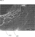
Die
Zum Herstellen der porösen DLC-Schicht
Mit Hilfe der Wechselspannungsversorgung
Die auf der Oberfläche
Als Rückätzgas ist insbesondere ein sauerstoffhaltiges Gas, beispielsweise reiner Sauerstoff O2, oder auch ein fluorhaltiges Gas, beispielsweise F2 oder Trifluormethan geeignet. Das Rückätzgas wird beispielsweise mit einer Flussrate von 90 cm3/min bei Standardbedingungen dem Rezipienten
Es hat sich herausgestellt, dass während des Rückätzschritts bevorzugt die sp2-Anteile der deponierten DLC-Schicht entfernt werden. Dieser selektive Ätzprozess konnte neben ebenfalls stattfindenden Selbstorganisationsprozessen als wesentlicher Mechanismus für das Entstehen der Poren
Sowohl für den Depositionsschritt als auch für den Rückätzschritt kann eine gemischte Atmosphäre verwendet werden, der neben dem Prozess- bzw. Rückätzgas eine Edelgaskomponente, beispielsweise Argon, beigemischt wird. Both for the deposition step and for the etching-back step, a mixed atmosphere can be used, to which a noble gas component, for example argon, is added in addition to the process or re-etching gas.
Um ein ausreichendes Schichtwachstum auf der Oberfläche
Es hat sich als vorteilhaft herausgestellt, wenn die Depositionsrate bzw. die deponierte Menge um ein Vielfaches größer ist als die Rückätzrate bzw. die rückgeätze Menge. Geeignete Faktoren sind beispielsweise 3, 5, 7, 10, 13, 15, 17 und 20. Höhere Rückätzraten sind gemäß einem Ausführungsbeispiel nicht vorgesehen. Mit anderen Worten beträgt also die Depositionsrate insbesondere maximal das Zwanzigfache der Rückätzrate. It has proven to be advantageous if the deposition rate or the amount deposited is many times greater than the re-etching rate or the amount repaid. Suitable factors are for example 3, 5, 7, 10, 13, 15, 17 and 20. Higher Rückätzraten are not provided according to an embodiment. In other words, the deposition rate is in particular at most twenty times the re-etching rate.
Ferner hat es sich als vorteilhaft erwiesen, wenn die Depositionsrate zwischen 100 nm/min und 160 nm/min, insbesondere zwischen 110 nm/min und 150 nm/min, ferner insbesondere zwischen 120 nm/min und 140 nm/min liegt. Mit anderen Worten sind also beispielsweise Depositionsraten von 100 nm/min, 110 nm/min, 120 nm/min, 130 nm/min, 140 nm/min oder 150 nm/min vorgesehen. Ferner hat es sich als vorteilhaft herausgestellt, wenn die Rückätzrate zwischen 10 nm/min und 20 nm/min, insbesondere zwischen 12 nm/min und 18 nm/min, ferner insbesondere zwischen 14 nm/min und 16 nm/min liegt. Mit anderen Worten sind also insbesondere Rückätzraten von 10 nm/min, 12 nm/min, 14 nm/min, 16 nm/min, 18 nm/min oder 20 nm/min vorgesehen.Furthermore, it has proven to be advantageous if the deposition rate between 100 nm / min and 160 nm / min, in particular between 110 nm / min and 150 nm / min, more particularly between 120 nm / min and 140 nm / min. In other words, for example, deposition rates of 100 nm / min, 110 nm / min, 120 nm / min, 130 nm / min, 140 nm / min or 150 nm / min are provided. Furthermore, it has been found to be advantageous if the re-etching rate is between 10 nm / min and 20 nm / min, in particular between 12 nm / min and 18 nm / min, and in particular between 14 nm / min and 16 nm / min. In other words, in particular, back-etching rates of 10 nm / min, 12 nm / min, 14 nm / min, 16 nm / min, 18 nm / min or 20 nm / min are provided.
Die poröse DLC-Schicht
Der Relaxationsschritt kann zwischen dem Depositions- und dem Rückätzschritt erfolgen, wobei zwischen jedem oder lediglich einigen der Depositions- und Rückätzschritten ein Relaxationsschritt vorgesehen wird. The relaxation step may be between the deposition and the etchback step, with a relaxation step provided between each or only some of the deposition and etchback steps.
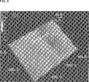
In
Es hat sich ferner herausgestellt, dass die Porengröße sehr gut über die Größe der BIAS-Spannung kontrollierbar ist. Dabei skaliert die mittlere Porengröße zumindest näherungsweise proportional mit der BIAS-Spannung. It has also been found that the pore size is very well controlled by the magnitude of the bias voltage. The average pore size scales at least approximately proportionally with the BIAS voltage.
Ein weiteres Ausführungsbeispiel ist ein Werkstück
Alle genannten Merkmale, auch die den Zeichnungen allein zu entnehmenden sowie auch einzelne Merkmale, die in Kombination mit anderen Merkmalen offenbart sind, werden allein und in Kombination als erfindungswesentlich angesehen. Erfindungsgemäße Ausführungsformen können durch einzelne Merkmale oder eine Kombination mehrerer Merkmale erfüllt sein. Im Rahmen der Erfindung sind Merkmale, die mit „insbesondere“ oder „vorzugsweise“ gekennzeichnet sind, als fakultative Merkmale zu verstehen.All mentioned features, including the drawings alone to be taken as well as individual features that are disclosed in combination with other features are considered alone and in combination as essential to the invention. Embodiments of the invention may be accomplished by individual features or a combination of several features. In the context of the invention, features which are identified by "particular" or "preferably" are to be understood as optional features.
BezugszeichenlisteLIST OF REFERENCE NUMBERS
- 22
- PECVD-Anlage PECVD system
- 44
- Rezipient recipient
- 66
- Anschlussflansch flange
- 77
- Pumpeneinheit pump unit
- 88th
- Gaseinlass gas inlet
- 99
- Drucksensor pressure sensor
- 1010
- Prozessgasversorgung Process gas supply
- 1111
- Massestromregler Mass flow controllers
- 1212
- Probenhalter sample holder
- 1313
- RF-Elektrode RF electrode
- 1414
- Hochspannungsversorgung High voltage power supply
- 1515
- Steuereinrichtung control device
- 1616
- Werkstück workpiece
- 1717
- Ventil Valve
- 1818
- Plasma plasma
- 2020
- Oberfläche surface
- 2222
- poröse DLC-Schicht porous DLC layer
- 2424
- Poren pore
- 2626
- Stent stent
- 2828
- Basismaterial base material
- 3030
- Haftvermittler bonding agent
- 3232
- Polymerschicht polymer layer
- MM
- Motor engine
Claims (10)
Priority Applications (3)
| Application Number | Priority Date | Filing Date | Title |
|---|---|---|---|
| DE102016200367.4A DE102016200367B3 (en) | 2016-01-14 | 2016-01-14 | Method for producing a thin layer of porous DLC, using a PECVD system and porous DLC coated workpiece |
| EP17708976.0A EP3402910B1 (en) | 2016-01-14 | 2017-01-13 | Process for producing a thin layer of porous dlc, use of a pecvd plant and workpiece coated with porous dlc |
| PCT/EP2017/050733 WO2017121885A2 (en) | 2016-01-14 | 2017-01-13 | Process for producing a thin layer of porous dlc, use of a pecvd plant and workpiece coated with porous dlc |
Applications Claiming Priority (1)
| Application Number | Priority Date | Filing Date | Title |
|---|---|---|---|
| DE102016200367.4A DE102016200367B3 (en) | 2016-01-14 | 2016-01-14 | Method for producing a thin layer of porous DLC, using a PECVD system and porous DLC coated workpiece |
Publications (1)
| Publication Number | Publication Date |
|---|---|
| DE102016200367B3 true DE102016200367B3 (en) | 2017-02-02 |
Family
ID=57795514
Family Applications (1)
| Application Number | Title | Priority Date | Filing Date |
|---|---|---|---|
| DE102016200367.4A Expired - Fee Related DE102016200367B3 (en) | 2016-01-14 | 2016-01-14 | Method for producing a thin layer of porous DLC, using a PECVD system and porous DLC coated workpiece |
Country Status (3)
| Country | Link |
|---|---|
| EP (1) | EP3402910B1 (en) |
| DE (1) | DE102016200367B3 (en) |
| WO (1) | WO2017121885A2 (en) |
Cited By (1)
| Publication number | Priority date | Publication date | Assignee | Title |
|---|---|---|---|---|
| WO2018157274A1 (en) * | 2017-02-28 | 2018-09-07 | 万魔声学科技有限公司 | Manufacturing method for diamond-like carbon vibrating diaphragm and loudspeaker |
Families Citing this family (1)
| Publication number | Priority date | Publication date | Assignee | Title |
|---|---|---|---|---|
| DE102017121684A1 (en) * | 2017-09-19 | 2019-03-21 | Technische Universität Darmstadt | Method for creating a structured surface |
Citations (4)
| Publication number | Priority date | Publication date | Assignee | Title |
|---|---|---|---|---|
| DE69612734T2 (en) * | 1995-11-02 | 2001-08-23 | Orion Electric Co Ltd | METHOD FOR PRODUCING DIAMOND-LIKE CARBON FILMS (DLC) |
| US8110493B1 (en) * | 2005-12-23 | 2012-02-07 | Novellus Systems, Inc. | Pulsed PECVD method for modulating hydrogen content in hard mask |
| US20140094035A1 (en) * | 2012-05-18 | 2014-04-03 | Novellus Systems, Inc. | Carbon deposition-etch-ash gap fill process |
| US20150104648A1 (en) * | 2013-10-15 | 2015-04-16 | Nano And Advanced Materials Institute Limited | Method and Apparatus of Growing Metal-free and Low Stress Thick Film of Diamond-like Carbon |
Family Cites Families (2)
| Publication number | Priority date | Publication date | Assignee | Title |
|---|---|---|---|---|
| US7384693B2 (en) * | 2004-04-28 | 2008-06-10 | Intel Corporation | Diamond-like carbon films with low dielectric constant and high mechanical strength |
| JP2009186236A (en) * | 2008-02-04 | 2009-08-20 | Seiko Epson Corp | Translucent member and watch having the same |
-
2016
- 2016-01-14 DE DE102016200367.4A patent/DE102016200367B3/en not_active Expired - Fee Related
-
2017
- 2017-01-13 EP EP17708976.0A patent/EP3402910B1/en active Active
- 2017-01-13 WO PCT/EP2017/050733 patent/WO2017121885A2/en not_active Ceased
Patent Citations (4)
| Publication number | Priority date | Publication date | Assignee | Title |
|---|---|---|---|---|
| DE69612734T2 (en) * | 1995-11-02 | 2001-08-23 | Orion Electric Co Ltd | METHOD FOR PRODUCING DIAMOND-LIKE CARBON FILMS (DLC) |
| US8110493B1 (en) * | 2005-12-23 | 2012-02-07 | Novellus Systems, Inc. | Pulsed PECVD method for modulating hydrogen content in hard mask |
| US20140094035A1 (en) * | 2012-05-18 | 2014-04-03 | Novellus Systems, Inc. | Carbon deposition-etch-ash gap fill process |
| US20150104648A1 (en) * | 2013-10-15 | 2015-04-16 | Nano And Advanced Materials Institute Limited | Method and Apparatus of Growing Metal-free and Low Stress Thick Film of Diamond-like Carbon |
Cited By (2)
| Publication number | Priority date | Publication date | Assignee | Title |
|---|---|---|---|---|
| WO2018157274A1 (en) * | 2017-02-28 | 2018-09-07 | 万魔声学科技有限公司 | Manufacturing method for diamond-like carbon vibrating diaphragm and loudspeaker |
| US10993058B2 (en) | 2017-02-28 | 2021-04-27 | 1More Inc | Manufacturing method for diamond-like carbon vibrating diaphragm and loudspeaker |
Also Published As
| Publication number | Publication date |
|---|---|
| WO2017121885A3 (en) | 2017-09-08 |
| EP3402910B1 (en) | 2019-10-23 |
| WO2017121885A2 (en) | 2017-07-20 |
| EP3402910A2 (en) | 2018-11-21 |
Similar Documents
| Publication | Publication Date | Title |
|---|---|---|
| EP1388594B1 (en) | Composite material with smooth barrier layer and process for its production | |
| DE19526387C2 (en) | Double-coated composite steel article and method for its production | |
| DE69417508T2 (en) | Process for applying a friction-reducing layer | |
| EP2041332B1 (en) | Method and device for plasma-assisted chemical vapour deposition on the inner wall of a hollow body | |
| EP1272683B2 (en) | Dlc layer system and method for producing said layer system | |
| EP2500446B1 (en) | Manipulator for the dynamic positioning of a substrate, coating method and the use of a manipulator | |
| DE102007047629A1 (en) | Method of applying a high-strength coating to workpieces and / or materials | |
| DE19929184A1 (en) | Radio frequency plasma enhanced chemical vapor deposition of diamond like films onto medical devices such as catheter wires | |
| EP2118332A2 (en) | Method for the production of a coating | |
| DE102015114479A1 (en) | MANUFACTURING METHOD FOR HARD SURFACE ELEMENT | |
| EP1032721A2 (en) | Wear-resistant, mechanically highly stressed and low-friction boundary coating construction for titanium or the alloys thereof and a method for producing the same | |
| DE102016200367B3 (en) | Method for producing a thin layer of porous DLC, using a PECVD system and porous DLC coated workpiece | |
| DE10258681A1 (en) | Process for applying alternating layers e.g. barrier layers onto a plastic bottle by chemical gas phase deposition comprises depositing an organic adhesion promoting layer on a substrate and applying an inorganic barrier layer | |
| DE102012211746B4 (en) | LOW-FRICTION COATING LAYER FOR A VEHICLE PART AND METHOD FOR PRODUCING THE SAME | |
| DE10149588A1 (en) | Formation of a diamond coating on a substrate, e.g. tools and precision components, comprises subjecting the substrate to a reactive gas mixture exited by a vacuum atmosphere by a plasma discharge | |
| EP0918586A1 (en) | Tool, especially for machining | |
| EP2705859A1 (en) | Coated intraocular lens and its production | |
| EP1088118B1 (en) | Method for applying a lubricating layer on an object and object with an adhesive lubricating layer | |
| WO2009030435A1 (en) | Method for the production of dlc layers and doped polymers or diamond-like carbon layers | |
| EP2354267A1 (en) | Method for producing a functional structured layer on a substrate and coating device and substrate plate for a coating device | |
| AT503050B1 (en) | Coating a tool with titanium, zirconium, hafnium, vanadium, niobium, tantalum or chromium carbonitride by chemical vapor deposition comprises increasing the temperature during deposition | |
| DE69421614T2 (en) | Sliding body | |
| DE3810851C2 (en) | Process for the production of molded parts | |
| DE19822935C2 (en) | Process for the adhesive application of a lubricant layer to an exposed and tribologically stressed surface of a molding tool, in particular a forming tool such as deep-drawing presses and the like, and molding tool with a lubricant layer adhering to its exposed surface | |
| DE60001673T2 (en) | METHOD FOR PRODUCING A DIAMOND-COATED METALLIC OBJECT, AND SUCH AN OBJECT MADE THEREOF |
Legal Events
| Date | Code | Title | Description |
|---|---|---|---|
| R012 | Request for examination validly filed | ||
| R018 | Grant decision by examination section/examining division | ||
| R020 | Patent grant now final | ||
| R119 | Application deemed withdrawn, or ip right lapsed, due to non-payment of renewal fee |