EP1017006A2 - Optischer Weg in einer Abtasteinheit in kompakten Strichkodelesern - Google Patents
Optischer Weg in einer Abtasteinheit in kompakten Strichkodelesern Download PDFInfo
- Publication number
- EP1017006A2 EP1017006A2 EP99125636A EP99125636A EP1017006A2 EP 1017006 A2 EP1017006 A2 EP 1017006A2 EP 99125636 A EP99125636 A EP 99125636A EP 99125636 A EP99125636 A EP 99125636A EP 1017006 A2 EP1017006 A2 EP 1017006A2
- Authority
- EP
- European Patent Office
- Prior art keywords
- light
- optical
- symbol
- assembly
- optical path
- Prior art date
- Legal status (The legal status is an assumption and is not a legal conclusion. Google has not performed a legal analysis and makes no representation as to the accuracy of the status listed.)
- Withdrawn
Links
Images


Classifications
-
- G—PHYSICS
- G06—COMPUTING; CALCULATING OR COUNTING
- G06K—GRAPHICAL DATA READING; PRESENTATION OF DATA; RECORD CARRIERS; HANDLING RECORD CARRIERS
- G06K7/00—Methods or arrangements for sensing record carriers, e.g. for reading patterns
- G06K7/10—Methods or arrangements for sensing record carriers, e.g. for reading patterns by electromagnetic radiation, e.g. optical sensing; by corpuscular radiation
- G06K7/10544—Methods or arrangements for sensing record carriers, e.g. for reading patterns by electromagnetic radiation, e.g. optical sensing; by corpuscular radiation by scanning of the records by radiation in the optical part of the electromagnetic spectrum
- G06K7/10821—Methods or arrangements for sensing record carriers, e.g. for reading patterns by electromagnetic radiation, e.g. optical sensing; by corpuscular radiation by scanning of the records by radiation in the optical part of the electromagnetic spectrum further details of bar or optical code scanning devices
- G06K7/10881—Methods or arrangements for sensing record carriers, e.g. for reading patterns by electromagnetic radiation, e.g. optical sensing; by corpuscular radiation by scanning of the records by radiation in the optical part of the electromagnetic spectrum further details of bar or optical code scanning devices constructional details of hand-held scanners
-
- G—PHYSICS
- G06—COMPUTING; CALCULATING OR COUNTING
- G06K—GRAPHICAL DATA READING; PRESENTATION OF DATA; RECORD CARRIERS; HANDLING RECORD CARRIERS
- G06K7/00—Methods or arrangements for sensing record carriers, e.g. for reading patterns
- G06K7/10—Methods or arrangements for sensing record carriers, e.g. for reading patterns by electromagnetic radiation, e.g. optical sensing; by corpuscular radiation
- G06K7/10544—Methods or arrangements for sensing record carriers, e.g. for reading patterns by electromagnetic radiation, e.g. optical sensing; by corpuscular radiation by scanning of the records by radiation in the optical part of the electromagnetic spectrum
- G06K7/10554—Moving beam scanning
- G06K7/10594—Beam path
- G06K7/10603—Basic scanning using moving elements
- G06K7/10633—Basic scanning using moving elements by oscillation
- G06K7/10643—Activating means
- G06K7/10653—Activating means using flexible or piezoelectric means
-
- G—PHYSICS
- G06—COMPUTING; CALCULATING OR COUNTING
- G06K—GRAPHICAL DATA READING; PRESENTATION OF DATA; RECORD CARRIERS; HANDLING RECORD CARRIERS
- G06K7/00—Methods or arrangements for sensing record carriers, e.g. for reading patterns
- G06K7/10—Methods or arrangements for sensing record carriers, e.g. for reading patterns by electromagnetic radiation, e.g. optical sensing; by corpuscular radiation
- G06K7/10544—Methods or arrangements for sensing record carriers, e.g. for reading patterns by electromagnetic radiation, e.g. optical sensing; by corpuscular radiation by scanning of the records by radiation in the optical part of the electromagnetic spectrum
- G06K7/10821—Methods or arrangements for sensing record carriers, e.g. for reading patterns by electromagnetic radiation, e.g. optical sensing; by corpuscular radiation by scanning of the records by radiation in the optical part of the electromagnetic spectrum further details of bar or optical code scanning devices
- G06K7/10881—Methods or arrangements for sensing record carriers, e.g. for reading patterns by electromagnetic radiation, e.g. optical sensing; by corpuscular radiation by scanning of the records by radiation in the optical part of the electromagnetic spectrum further details of bar or optical code scanning devices constructional details of hand-held scanners
- G06K7/109—Methods or arrangements for sensing record carriers, e.g. for reading patterns by electromagnetic radiation, e.g. optical sensing; by corpuscular radiation by scanning of the records by radiation in the optical part of the electromagnetic spectrum further details of bar or optical code scanning devices constructional details of hand-held scanners adaptations to make the hand-held scanner useable as a fixed scanner
Definitions
- the field of the invention relates to electro-optical readers or scanning systems, such as bar code symbol readers, and more particularly to the optical path design in a scanning module for use in applications requiring particularly compact bar code readers.
- Electro-optical readers such as bar code symbol readers, are now very common.
- a bar code symbol comprises one or more rows of light and dark regions, typically in the form of rectangle.
- the widths of the dark regions i.e., the bars and/or the widths of the light regions, i.e., the spaces, between the bars encode information in the symbol.
- a bar code symbol reader illuminates the symbol and senses light reflected from the regions of differing light reflectivity to detect the relative widths and spacings of the regions and derive the encoded information.
- Bar code reading type data input systems improve the efficiency and accuracy of data input for a wide variety of applications. The ease of data input in such systems facilitates more frequent and detailed data input, for example to provide efficient inventories, tracking of work in progress, etc. To achieve these advantages, however, users or employees must be willing to consistently use the readers. The readers therefore must be easy and convenient to operate.
- a variety of scanning systems are known.
- One particularly advantageous type of reader is an optical scanner which scans a beam of light, such as a laser beam, across the symbols.
- Laser scanner systems and components of the type exemplified by U.S. Patent Nos. 4,387,297 and 4,760,248 which are owned by the assignee of the instant invention and are incorporated by reference herein have generally been designed to read indicia having parts of different light reflectivity, i.e., bar code symbols, particularly of the Universal Product Code (UPC) type, at a certain working range or reading distance from a hand-held or stationary scanner.
- UPC Universal Product Code
- U.S. Patent No. 4,251,798 discloses a rotating polygon having a planar mirror at each side, each mirror tracing a scan line across the symbol.
- U.S. Patent Nos. 4,387,297 and 4,409,470 both employ a planar minor which is repetitively and reciprocally driven in alternate circumferential directions about a drive shaft on which the mirror is mounted.
- U.S. Patent No. 4,816,660 discloses a multi-mirror construction composed of a generally concave mirror portion and a generally planar mirror portion. The multi-minor construction is repetitively reciprocally driven in alternative circumferential directions about a drive shaft on which the multi-minor construction is mounted. All of the above-mentioned US Patents are incorporated herein by reference.
- the "scan engine” including the laser source, the optics the mirror structure, the drive to oscillate the mirror structure, the photodetector, and the associated signal processing and decoding circuitry all add size and weight to the scanner.
- a large heavy hand-held scanner can produce user fatigue.
- the user is reluctant to operate the scanner. Any reluctance to consistently use the scanner defeats the data gathering purposes for which such bar code systems are intended.
- an ongoing objective of bar code reader development is to miniaturize the reader as much as possible, and a need still exists to further reduce the size and weight of the scan engine and to provide a particularly convenient to use scanner.
- the mass of the moving components should be as low as possible to minimize the power required to produce the scanning movement.
- a related object is to develop an electro-optical scanning system which is both smaller and lighter in weight.
- a related object is to provide a module which may be assembled easily.
- the present invention provides an optical scan module including a base; a light source supported by the base, for generating and directing a light beam along a first segment of a first optical path to a symbol to be read; an optical assembly including a light-collecting portion for collecting and re-directing the reflected light along a second optical path, having an optical axis that is displaced from said first segment of the first optical path; a scan assembly including a reciprocally oscillatable scan mirror mounted for oscillating movement, and operative for receiving the light beam transmitted on the first segment of the first optical path, and for directing the light beam along a second segment of the first optical path through the window and exteriorly of the housing module; and a sensor supported by the base for detecting the collected reflected light that has been re-directed by the light-collecting portion, and for generating an electrical signal corresponding to the detected light intensity.
- a bar code reader having a housing with a window, including an optical scan module having mounted thereon:
- a small-size optical scan module in the form factor of a substantially rectangular parallelepiped module having dimensions approximately 20.6 mm X 14.2 mm X 11.4 mm.
- a light source for emitting a light beam
- a scanning assembly for receiving said light beam and for generating therefrom a scanning beam directed to an indicia to be read
- a detector for detecting reflected light and to direct it to said detector.
- the light source is mounted on a first one of the peripheral sides (i.e. a 10.4 mm X 20.6 mm side), the scanning assembly is mounted on a first base side (i.e. the 20.6 mm X 14.2 mm side), the collection mirror is mounted on one of the base sides, and the detector mounted on one of the base sides.
- the base sides may be formed from a printed circuit board, while the peripheral side on which the light source is mounted forms part of an integral metal or plastic chassis of the module.
- the light source is mounted on a first one of the peripheral sides (i.e. a 20.6 mm X 14.2 mm side)
- the scanning assembly is mounted on the second base side (i.e. the other 20.6 mm X 14.2 mm side)
- the collection mirror is mounted on the first or second base side
- the detector mounted on the first or second base.
- the second base side is formed from a printed circuit.
- the scanning assembly and the detector are mounted on the same basic side, and the collection mirror is mounted on the opposite base side.
- the components with electrical connections are mounted on the printed circuit base side, while the critical optical components (the laser and collection mirror) are positioned in an integral chassis which forms the other base side and at least one of the peripheral sides.
- a fourth embodiment in the same form factor, all the components are mounted on a first one of the base sides (i.e. a 10.4 mm X 20.6 mm side), which is formed from a printed circuit board.
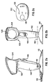
- Figure 1 shows a low-cost optical assembly, according to the preferred embodiment, for creating a scanning laser beam for use in a bar code reader.
- the optical assembly comprises two essentially separate portions, the "static optics" 10 and the scanner motor drive 12, both mounted to a common support or printed circuit board (PCB) 14.
- PCB printed circuit board
- the light beam 16 from a semiconductor laser 18 passes through a molded plastics lens 20 and is turned through 90° by total internal reflection from a prism 22. After exiting the prism, the beam passes through an aperture 24 in a collector mirror 26, and impinges onto an oscillating scanning mirror 28. This produces a scanning o outgoing light beam 30, which is directed toward an indicia (not shown) to be read.
- the mirror 28 is shown as being angled, this is merely a drawing representation to render the shape and operation of the mirror clearer.
- the minor sweeps a beam in the plane of the paper on which the drawing is presented, and orthogonal to the PCB 14.
- Reflected light 32 from the indicia is first received by the scanning minor 28, which directs it onto a concave surface 34 of the collector mirror 36. This focuses the light via an aperture 36 and a filter 38 onto a photodetector 40. The photodetector output signal is then passed on to suitable electronics within the PCB 14 by an electrical coupling 42.
- the scanning mirror 28 is mounted at 44 for oscillation about an axis, this being achieved by virtue of the interaction between a permanent magnet 46 and a driven electromagnetic coil 48.
- a suitable driving signal is applied to the coil, via the PCB 14 and coil electrical contact 50.
- the scanner motor drive 12 shown in Figure 1 is exemplary, and may be replaced with any type of mechanism for effecting a scanning motion of the laser beam in one or two dimensions.
- the scanner motor drive could comprise any of the configurations disclosed in US Patents Nos. 5,581,067 and 5,367,151, all of which are incorporated by reference. In this way, the static optics assembly 10 may be used as a component in a variety of scanner designs.
- a light masking aperture 36 may be used in front of the photodetector 40, as shown in Figure 1, for increasing the depth of focus of the photodetector, the same effect can be achieved without an aperture by appropriately specifying the area of the photodetector 40 itself.
- the aperture 24 is located in a position in the collector minor 26 so that the beam path of the outgoing laser beam striking the minor 28 is offset from the optical axis of the reflected light from the concave surface 34 of the collector mirror 26.
- the aperture 24 is located below the optical axis of the collector mirror 26, as shown in Figure 1 (and in the corresponding components in Figure 11).
- Bar code readers utilizing such modules or optical assemblies with prior art optical path designs would avoid such difficulties by typically utilizing a window that was mounted at an acute angle with respect to the outgoing laser beam (see, for example, the placement of the windows in the bar code readers depicted in U.S. Patents 4,387,297; 4,409,470; 4,816,660; and 5,280,164). Any internal reflection from such tilted windows would be in a direction away from the optical assembly, thereby reducing the noise of the signal received by the photodetector.
- Such tilted window configurations require, however, more effort to implement mechanically, and increase the overall size of the housing.
- the design of the optical path in the scan module according to the present invention permits the scan module to be mounted on a PCB, such as shown in Fig. 2d, so that the window can be placed flush with the surface of the housing and consequently orthogonal to the emitted laser beam.
- the scan module could also be mounted flush against the window for an even more compact arrangement.
- reflected light from the window is returned in the direction of the beam path of the outgoing laser beam
- the optical path design of the assembly of Figure 1 the outgoing laser beam optical path is different from the optical axis of the reflected light from the light collecting portion.
- such internally reflected light would not be directed by the light collecting portion to the photodetector 40, and therefore would not effect the signal from the light reflected by the bar code symbol..
- the implementation of the above-described offset outgoing and return light paths does not require the use of an apertured collector mirror 26.
- the laser light source and the photodetector must be positioned with respect to one another simply so that the emitted light beam partially reflected by the window and reflected by the light-collecting portion does not illuminate the photodetector, i.e. by having spaced-apart, or offset, optical axes.
- optical assembly shown in Figure 1 may be incorporated within any type of fixed or portable optical scanner, for example the scan-type scanner of Figs. 2a-2c the hand-held scanner shown in Figure 2d or the hand-held computer terminal/scanner shown in Figure 2e.
- the scanner includes a scanner body designated generated 100 including a handle portion 102 and a head portion 104.
- the handle portion 102 is configured to be held upright in the user's palm and has a forward portion including a trigger 106 positioned preferably to be operable by the user's forefinger.
- the head portion 104 is provided at the top of the handle portion 102 and includes a front face including a scanning window 108 and a bulbous rear portion extending rearwardly from the handle 102 to rest on or above the user's hand in use.
- the scanner 100 is pivotably fixed to a base portion 110 about a pivot axis 112 provided at the lower end of the handle 102.
- the base includes a flat bottom face 114 and extends outwardly from the handle portion both forward and rear and to the sides such that the assembly as a whole can be placed freestanding stabily on a supporting surface.
- the scanner 100 is arranged to pivot on the base 110 in the forward/backward direction.
- the base 100 provides an interface between the scanner 100 and a host (not shown) by a cable 116.
- the cable 116 can simply carry power or can also include a data path either for control information to be passed to the scanner or for data read to be downloaded to the host from the scanner 100.
- the base 110 includes on its underside 114 a pressure switch of any suitable known type (not shown) release of which indicates to a processor in the scanner that the scanner is being operated in hand-held mode. Accordingly the scanner switches to triggered mode indicating that reading will only take place when trigger 106 is activated.
- control system is illustrated in more detail in the flow chart of Fig. 4. It will be seen that a continuous loop is maintained by a suitable controller establishing whether or not the pressure switch is activated (step 150). If the pressure switch is deactivated then triggered (hand-held) mode is entered (step 152); further discussion of relevant features may be found in US 5,151,581, incorporated herein by reference.
- continuous scanning (hand free) mode 154 is entered.
- a presentation scan pattern is always activated allowing all items to pass in front of the scanner to be scanned. This can be used for example at a retail sales point such as a check-out stand. Accordingly the arrangement allows dual mode operation.
- the scanner 100 shown in the Figure is an omnidirectional scanner but the gun-type configuration provides the benefits of a conventional one-dimensional scanner.
- the adjustable angle provided by the incorporation of a pivot axis 112 allows the scanner as a whole to be positioned at any desired pivot angle for ease of reading and also allows the base to be angled to a comfortable position when in hand-held mode.
- the main body 100 and base 110 are preferably modular such that one or other components can be changed at minimum expense to arrive at, for example, a cordless embodiment.
- a mode button 118 is additionally provided on the upper face of the head 104 (see Fig. 2c) allowing the user to select a scanning pattern of any desired type for example based on the bar code symbols or other indicia to be read, or the scanning conditions.
- indicator lights such as LEDs are provided at 120 which can indicate, for example, the mode of operation of the scanner, whether it is in hands-free or hand-held mode, and so forth.
- reference numeral 210 generally identifies a hand-held scanner in an alternative embodiment.
- the scanner may alternatively be gun-shaped, or any suitable configuration may be used.
- the scanner is manually-operable for example by a trigger (not shown).
- a light source component typically but not necessarily a laser, is mounted inside the scanner shown at block 210.
- the light source emits a light beam along a transmission path which extends outwardly through a window 218 that faces indicia, e.g. bar code symbols, to be read.
- a photodetector component e.g. a photodiode, having a field of view, and operative for collecting reflected light returning through the window 214 along a path from the symbol.
- the optical assembly of Figure 1 is mounted within or as part of the block 210.
- the photodetector generates an electrical analog signal indicative of the variable intensity of the reflected light.
- This analog signal is convened into a digital signal by an analog-to-digital converter circuit.
- This digital signal is decoded by a decode module 222.
- the decode module 222 decodes the digital signal into data descriptive of the symbol.
- An external host device 224 usually a computer, serves mainly as a data storage in which the data generated by the decode module 222 is stored for subsequent processing.
- the block 210 and decoder 222 are mounted on a PCB 214.
- the user aims the scanner at the symbol and pulls the trigger or otherwise initiates reading of the symbol.
- the trigger is an electrical switch that actuates the drive means.
- the symbol is repetitively scanned a plurality of times per second, e.g. more than 100 times per second. As soon as the symbol has been successfully decoded and read, the scanning action is automatically terminated, thereby enabling the scanner to be directed to the next symbol to be read in its respective turn.
- the head need not be a portable hand-held type as fixedly mounted heads are also contemplated in this invention.
- the heads may have manually operated triggers, or may be continuously operated by direct connection to an electrical source.
- the oscillations need only last a second or so, since the multiple oscillations, rather than time, increase the probability of getting a successful decode for a symbol, even a poorly printed one.
- the resonating reflector has a predetermined, predictable, known, generally uniform, angular speed for increased system reliability.
- FIG. 2e there is shown an alternative hand-held optical scanner including additional features, this time taking the form of a scanning terminal 326.
- the terminal comprises a hand-held case 328 having a data display screen 30 and a data input keypad 332.
- the optical assembly of Figure 1 within the case 328, produces a scanning light beam which extends outwardly through a window 334 which faces the indicia to be read. Light reflected from the indicia passes back through the window 334 and impinges on the photodetector component, for example a photodiode, which creates a returning light output signal.
- the information content within that signal may be stored in an on-board memory (not shown) or may be downloaded to a remote computer via a data port 336. Alternatively, the information may be transmitted via a radio frequency signal produced by an on-board radio transmitter/receiver 338.
- the motor drive used to obtain scanning action is preferably a "taut band element” drive.
- This type of drive is fully described in, inter alia, US Patents 5,614,706 and 5,665,954 which are commonly assigned herewith and incorporated herein by reference.
- the arrangement includes an optical element such as a lightweight mirror mounted on a thin flexible strip (the "taut band") mounted across an electromagnetic coil.
- a permanent magnet is attached to the optical element which interacts with a varying magnetic field created when an AC signal is applied to the coil to cause repetitive torsional motion in the flexible strip. As a result the optical element oscillates providing scanning motion.
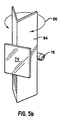
- Fig. 5a shows a taut band element drive of known type in more detail.
- coil 70, flexible strip 72, minor 74 and permanent magnet 76 can be seen.
- the flexible strip 72 can be held against the coil 70 for example by a holding annulus 78.
- An AC voltage applied to the coil is represented schematically at 80 and causes torsional oscillation represented schematically by arrow 82. It will be apparent that this arrangement can replace the arrangement shown generally in Fig. 1 as minor 28 and drive arrangement 44,46,48 in a manner apparent to the skilled reader.
- the flexible strip 72 is replaced by an elongate element 84 which is V-shaped in cross-section perpendicular to its elongate axis on which is mounted the mirror 74 and permanent magnet element 76.
- the V-shaped element 84 extends across a coil or is otherwise appropriately mounted in the same manner as previous thin flexible element 72 and the permanent magnet 76 interacts with the AC magnetic field resulting in torsional deflection represented by arrow 86.
- the V-shaped cross section of the band increases its stiffness and in particular ensures that the torsional deflection is uniform or substantially uniform over the length of the band, the mirror 74 being mounted on the apex of the "V".
- band cross section can be contemplated such as X shaped, I or H shaped, W shaped as long as the requirements of torsional deflection and uniformity of that torsional deflection along the length of the band are maintained.
- Fig. 6 shows in exploded form a practical mode of mounting the V shaped element 84 of Fig. 5b.
- Coil 70 is mounted on an E-configuration core 71a including a central arm 71b which is received in the central recess of the coil 70 and outer arms 71c and 71d which extend either side of the coil and above it.
- a mounting plate 75a is received on the outer arm 71c,71d of the Ecore and extends above and across the coil 70.
- the mounting plate 75a includes a central aperture 75b defining the space across which the V-shaped element 84 extends.
- the V-shaped element 84 includes limbs 84a extending either side of its longitudinal axis symmetrically at either end and the centre and is mounted on the mounting plate 75a across the aperture 75b in any suitable manner, for example by securing the end limbs 84a to the upper face of the mounting place 75a.
- Cooperatingly configured V-shaped connecting elements 85 are secured to the V-shaped element 84 and generally aligned with the limbs 84a and the mirror 74 is mounted on the connecting elements 85 at the apex of the V-shaped element.
- a yoke 73 also substantially of V shaped but straddling the V-shaped element 84, having its outer ends 73a,73b attached to the rear of the mirror 74.
- the yoke 73 has a central portion which extends away from the mirror 74 and has lateral tabs 73c,73d.
- the lateral tabs 73c and 73d are in register with the central limbs 84a,84b of the V-shaped element and are attached thereto.
- the permanent magnet 76 is attached to the underside of the central portion of the yoke 73 for example to the underside of the tabs 73c and 73d. Accordingly the yoke 73 straddles the V-shaped element 84 such that the permanent magnet projects over or through the aperture 75b in the mounting plate 75a allowing optimum magnetic coupling with the coil 70.
- the permanent magnet 76 oscillates which in turn gives rise to torsional flexing of the V-shaped element 84 and oscillation of the mirror 74.
- the assembled arrangement is shown in Fig. 7.
- FIG. 8 An assembled module incorporating the arrangement of Fig. 7 is shown in Fig. 8 in which it will be seen that a substantially cuboidal housing is incorporated. The direction of angular motion of the minor is depicted by arrow A.
- the type of motor drive used to oscillate the scan minor can be a Mylar leaf spring supporting an unbalanced minor assembly.
- the minor assembly is mounted to a Mylar leaf spring which flexes as the permanent magnet is driven by the AC coil imparting an oscillating force.
- Still a further alternative is a "micro machined" minor assembly as discussed in U.S. Patent Application Serial Nos. 08/506,574 and 08/631,364 according to which the minor is driven back and forth directly by a suitable drive motor, preferably of very small dimension.
- a mirror of known rotating polygon type as discussed in the introduction in relation to US Patent No. 4,251,798 according to which the minor comprises a solid body having a plurality of face angled to one another. As the body rotates the beam is scanned by successive rotating faces of the polygon body.
- the Mylar motor can be used in an arrangement for one dimensional scanning while a V-shaped taut band element (described above) can be used for two dimensional scanning also as discussed in more detail below.
- the laser focusing lens 20, the laser aperture 24 and the collection minor 26 are all defined by a single molded plastics material member, shown in cross-hatching and indicated generally by the reference numeral 52.
- the molded member 52 farther acts to house and to locate the laser 18, the filter 38 and the photodetector 40.
- the preferred laser 18 is a semiconductor laser is mounted by conventional through-hole techniques on the PCB.
- the photodiode is preferably an SMD ("surface mounted device") device as is the AC coil for the Mylar leaf spring motor.. This eliminates the need for standoffs and hand-soldering or sockets, as are used on prior art scanners.
- the laser will be a standard packaged edge-emitting laser.
- the laser focusing is not adjustable, and the laser is simply installed with its mounting flange in contact with a shoulder molded as part of the molded member. This will position the laser accurately enough with respect to the molded focusing lens 20 to provide adequate performance within an inexpensive scanner.
- the fact that the focusing lens is molded as part of the same component as the shoulder 54 minimizes tolerance build-ups that could otherwise cause improper focusing.
- the laser is held in place within the molded member 52 by means of W-curing cement. Since the plastics material of the molded member is transparent to W light, the cement may be cured by shining UV light through the member into the cavity within which the laser is positioned. Cement may be applied to the laser 18, or to the molded member 52, with the laser then being pushed into the cavity until it abuts the positioning shoulder 54. The assembly may then be exposed to ultraviolet light for a few seconds, so curing the cement. If desired for higher performance, this method of retaining the laser also allows for a focusing adjustment to be made. In this case, the laser is gradually slid into the cavity while the output beam is being monitored. When correct focus is achieved, the assembly is exposed to W light, thus curing the cement and locking the assembly into place.
- the laser 18 has downwardly-extending electrical leads 58 which are simply installed directly into the PCB 14. This eliminates hand-soldering, but soldering could be used if desired.
- the fact that the leads extend downwardly into the circuit board means that in a conventional laser, the beam will be directly upwardly perpendicular to the board.
- the prism 22, previously described, is molded into the top of the molded member 52 to direct the vertical laser beam through the aperture 24 in the collector mirror 26 towards the scanning mirror 28.
- the prism 22 uses total internal reflection to reflect the laser beam, so it is not necessary to coat the upper surface with a reflective coating.
- the laser beam should pass through a beam stop.
- the aperture 24 in the collector mirror 26 may serve this purpose.
- the lens 20 or the reflecting or exit surface of the prism 22 could provide the beam stop.
- the aperture 24 may be in the region of 0.5mm in diameter. This provides an additional advantage as the resulting diffraction pattern gives rise to a light distribution following a Bessel function which is particularly well adapted for scanning indicia.
- the molded member 52 needs to be secured to the circuit board 14, and to that end snaps 62,64 are provided. These automatically latch onto the circuit board when the component is installed.
- posts on the lower side of the molded member may protrude through the board to be heat-staked onto the bottom of the board. Ultrasonic staking could also be used.
- the collector mirror 26 is coated with a reflective coating so that light impinging upon it will be reflected downwardly toward the photodetector 40. This coating may also cover that part 62 of the molded member that serves as a housing for the photodiode. This will render the optics assembly opaque in that area to prevent any light from reaching the photodiode except via the aperture 36 and the filter 38.
- This reflective coating may also serve another function.
- the coating will be a thin film of metal such as gold, aluminum or chrome. These films are electrically conductive. A Accordingly, the film also acts as an electromagnetic interference shield for the photodiode 40.
- the use of a surface coating to protect the photodiode enables the usual EMI shield to be dispensed with, thereby eliminating both the cost of a separate shield and the labor to have it installed within the assembly.
- the coating is electrically grounded by extending a projection 66 of the molded member into a small socket 68 in the PCB.
- the projection 66 could be press-fitted into a plated through-hole in the board.
- the housing portion 62 of the molded member 52 not only acts to hold the optical filter 38 in place on top of the photodiode 40, but also entirely surrounds the photodiode, thereby preventing stray light from reaching it.
- the aperture 36 in the housing may be small to limit the f field of view of the detector, maximizing ambient light immunity.
- the aperture needs to be accurately located with respect to the collector mirror 26, to allow the use of a minimum-sized field of view. Accurate relative positions of the aperture and the collector minor are easily achieved since they are molded as a single part.
- FIG. 3 An alternative arrangement is shown in Fig. 3.
- the beam 30 leaves the optical assembly at an angle other than 90° to the vertical (relative to the PCB 14).
- the mounting requirements mean that the PCB 14 is mounted at a non-orthogonal position.
- This problem is solved in the arrangement according to Figure 3 by adjusting the angle by which the beam exits the optical assembly to compensate for the mounting angle and remove the need to mount the PCB including a spacer.
- the angle involved is dependent on the particular consumer requirements but may be in the region of 45-90° to the PC board, more preferably in the range of 60-70° and most preferably 65° to the PCB.
- Figs. 11 and 12 show an alternative optical assembly and motor drive embodiment to Fig. 3 according to an embodiment of the invention.
- the arrangement is mounted on a single base board 500 and includes a laser assembly 502 of suitable type for example of the type discussed above.
- the laser assembly 502 may be mounted on the chassis including peripheral side 550, which also acts as a beat sink for the laser.
- a beam from the laser assembly 502 is not folded, but directly passes through an aperture 504 in a collector minor 506 and is reflected by a scanning minor 508. The returning beam is retroreflected onto the collector minor 506 and directed to a detector of suitable known type 510.
- the minor is mounted in conjunction with a permanent magnet 512 which interacts with a magnetic field provided by an AC current driven coil 514 to oscillate the mirror.
- the mirror is mounted relative to the base 500 via an attachment element 501 which is connected to the minor by two Mylar springs 518,520.
- the attachment element 516 is mounted parallel to the base and the Mylar springs which extend perpendicular to the attachment strip 516 are hence at 25° to the vertical.
- a scanning plane is defined at 25° to the vertical as discussed in more detail below. It will be appreciated, of course, that any appropriate angle can be selected.
- the scan angle is then defined by the amplitude of motion of the minor and is preferably selected to be 50°.
- the minor assembly is of the unbalanced type, that is, no counterweights are provided against the mirror mass as considered relative to the point of support.
- an unbalanced mirror i.e. one in which no counterweights are provided in the mirror assembly
- the mirror is driven at a speed of greater than 100 scans per second.
- gravity will exert a relatively greater force on the side of the mirror assembly having the greater mass, causing the mirror to "droop" on its heavier side and pull on the flexible springs.
- the effect of such force depends on the orientation of the scanner with respect to the force vector of gravity.
- a balanced mirror requires additional mass be added to the mirror, or minor assembly, which is a drawback in terms of operating design weight and consequentially the power requirements.
- the material composition, size, shape and thickness of the spring may be appropriately selected to achieve the desired resonant frequency.
- the selection of a Mylar spring with a thickness of 4 mil is appropriate.
- a stainless steel spring with a thickness of about 3 mil is preferred.
- the mirror 508 is angled relative to the vertical to direct the scanning beam out of the upper face of the assembly.
- the mirror 508 is represented in Fig. 11 as being also angled out of a plane orthogonal with a plane of the paper, this is merely a drawing representation to render the figure clearer.
- the attachment element 516 includes limbs 522 and 524 extending either side of the Mylar springs 518,520.
- limbs are positioned within shaped recesses in side blocks 526,528 allowing a certain amount of clearance for the limbs which provides adequate space for the desired scanning angle to be achieved while providing stops to limit the amount of oscillation of the mirror should a shock be imparted to the unit, for example by dropping it.
- a beam emitted by the laser assembly 502 incident on the mirror 508 is swept through an angle of 50° by the scanning mirror, however the plane of sweep of the beam (the scan plane) is not at 90° to the base 500 but is at an angle constrained by the direction in which the magnet is driven to oscillate i.e. the axis of flexing of the Mylar springs.
- the laser beam 30 enters in the Y direction.
- the mirror and drive assembly are not shown but in Fig. 13a the normal mirror configuration is assumed that is the mirror is angled at 45° to the X Z plane and is mounted to oscillate about the X direction.
- a scan plane 530 is established in the Y Z plane.
- the mirror and mirror drive are mounted as discussed in relation to Figs. 11 and 12. It will be seen, therefore, that the scan line is obtained in a plane 532 at 25° to the Y Z plane. Again, any desired scan plane angle or scanning angle can be selected.
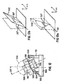
- Fig. 9 shows a second preferred embodiment in which two-dimensional scanning motion is achieved by using two mirrors each oscillating in an orthogonal claim.
- Multi-pattern scanners can be achieved by using two reflector X-Y motion as described in US 5,581,070, US 5,637,856 and US 5,614,706 all of which are incorporated herein by reference.
- the two reflectors are driven by a thin flexible element-type drive of the type shown in Fig. 5a or Fig. 7.
- the optical module 10 emits a beam 30 through aperture 24 in collector 34 which is oscillated in a first direction for example the X direction by a first oscillating mirror 28a mounted on a first V-shaped element 84 and is then oscillated in a second direction for example the Y direction by a second mirror 28b mounted on a V-shaped band 84.
- any desired scanning pattern can be achieved at the target as represented schematically by pattern 11.
- All of the elements are preferably provided in a single module as can be seen from the base lay out depicted in Fig. 10.
- laser 18 emits an outgoing beam 30 through an aperture 34 in collector minor 26.
- the beam is oscillated in the X direction by minor 28a and in the Y direction by minor 28b giving rise to a scanning pattern shown schematically at 11.
- the returning beam 32 returns along the reflection path and is directed onto the detector 40 by the collector mirror 26. It will of course be appreciated that the arrangement is preferably used in conjunction with the optical assembly shown in Fig. 1 and the exact positioning and orientation of the parts will be apparent to the skilled reader.
- Fig. 14 shows an alternative scan engine form-factor and ergonomic housing variation for incorporation of the scanner described herein or any other suitably dimensioned scanner.
- the scanner is incorporated into a pen-type housing 600 having a scanning window 602.
- the pen-type housing 600 is preferably elongate having broad front and rear faces 604,606 and narrow side faces.
- the scanning window is preferably provided at the upper end of broad face 604, at the opposite end to the pen "nib" 612. Scanning can be triggered by one or more triggers 608,610 provided for example on the side or front face of the pen housing 600.
- the pen nib 612 can either be a conventional pen or an electronic pen. Because of the broad faces the arrangement easily houses a scanner module of the type described herein.
- the positioning of the window 602 allows ergonomic scanning and the positioning of a plurality of triggers allows left or right handed users to use the scanner with ease. It will be seen that the broad rear face 606 of the housing 600 contacts the user's palm in reading mode for comfort and ease of use while in the writing mode the narrow side face contacts the user's palm, so that the arrangement can be used normally as a pen.
- the window 602 is shown in Figure 14 with its shorter side parallel to the axis of the pen, alternatively the longer side may be positioned parallel to the axis with the direction of the scan line also parallel to the axis of the pen.
- the invention relates to in an electro-optical reader having a housing with a window through which passes alight beam directed to, and light reflected from, bar code symbols to be read, a retro-reflective optical scan module comprising: a support; a light source mounted on the support, for generating and directing the light beam along a first segment of a first optical path to a symbol to be read; and an optical assembly including a light-collecting portion for collecting and re-directing the reflected light along a second optical path.
Applications Claiming Priority (2)
| Application Number | Priority Date | Filing Date | Title |
|---|---|---|---|
| US09/223,482 US6491222B1 (en) | 1996-10-09 | 1998-12-30 | Optical path design for scanning assembly in compact bar code readers |
| US223482 | 1998-12-30 |
Publications (2)
| Publication Number | Publication Date |
|---|---|
| EP1017006A2 true EP1017006A2 (de) | 2000-07-05 |
| EP1017006A3 EP1017006A3 (de) | 2002-05-29 |
Family
ID=22836695
Family Applications (1)
| Application Number | Title | Priority Date | Filing Date |
|---|---|---|---|
| EP99125636A Withdrawn EP1017006A3 (de) | 1998-12-30 | 1999-12-22 | Optischer Weg in einer Abtasteinheit in kompakten Strichkodelesern |
Country Status (5)
| Country | Link |
|---|---|
| US (1) | US6491222B1 (de) |
| EP (1) | EP1017006A3 (de) |
| JP (1) | JP3778416B2 (de) |
| CN (1) | CN1174336C (de) |
| TW (1) | TW480452B (de) |
Cited By (3)
| Publication number | Priority date | Publication date | Assignee | Title |
|---|---|---|---|---|
| EP1274039A2 (de) * | 2001-07-03 | 2003-01-08 | Symbol Technologies, Inc. | Kompaktes Scannermodul mit magnetisch zentriertem Abtastspiegel |
| EP1308875A2 (de) * | 2001-11-06 | 2003-05-07 | Symbol Technologies, Inc. | Hochgeschwindigkeitslaserabtastmodul mit gefaltetem Strahlengang |
| CN102170512A (zh) * | 2011-02-18 | 2011-08-31 | 深圳市乐州光电技术有限公司 | 双通道阅读器 |
Families Citing this family (30)
| Publication number | Priority date | Publication date | Assignee | Title |
|---|---|---|---|---|
| US6527180B1 (en) * | 1993-11-17 | 2003-03-04 | Symbol Technologies, Inc. | Compact dual optical and scan modules in bar code readers |
| US6715685B2 (en) * | 1993-11-17 | 2004-04-06 | Symbol Technologies, Inc. | Optical path design for scanning assembly in compact bar code readers |
| US7157302B2 (en) * | 1998-06-04 | 2007-01-02 | Micron Technology, Inc. | Imaging device and method of manufacture |
| US6829046B1 (en) * | 2000-12-01 | 2004-12-07 | Delaware Capital Formation, Inc. | Vehicle measuring system |
| US6766954B2 (en) | 2001-06-15 | 2004-07-27 | Symbol Technologies, Inc. | Omnidirectional linear sensor-based code reading engines |
| US7055747B2 (en) * | 2002-06-11 | 2006-06-06 | Hand Held Products, Inc. | Long range optical reader |
| US7090135B2 (en) * | 2003-07-07 | 2006-08-15 | Symbol Technologies, Inc. | Imaging arrangement and barcode imager for imaging an optical code or target at a plurality of focal planes |
| US7306154B2 (en) | 2004-10-21 | 2007-12-11 | Optoelectronics Co., Ltd. | Barcode scanning system with a compensation circuit |
| US7281658B2 (en) * | 2005-01-31 | 2007-10-16 | Symbol Technologies, Inc. | Scan module |
| US8002183B2 (en) | 2005-10-20 | 2011-08-23 | Metrologic Instruments, Inc. | Scanner flipper integrity indicator |
| US9242889B2 (en) | 2005-11-18 | 2016-01-26 | Hoya Corporation | Method of manufacturing formed article, glass material, and method of determining shape of glass material and mold |
| US8500025B2 (en) * | 2006-11-09 | 2013-08-06 | Optoelectronics Co., Ltd. | Compact bar code scanner assembly |
| US7832641B2 (en) | 2007-05-24 | 2010-11-16 | Metrologic Instruments, Inc. | Scanner switched to active state by sensed movement in quiescent scanning mechanism |
| EP2402132A4 (de) * | 2009-02-27 | 2014-10-15 | Hoya Corp | Vorrichtung zur herstellung einer form für eine linse und verfahren zur herstellung eines brillenglases |
| WO2010098137A1 (ja) * | 2009-02-27 | 2010-09-02 | Hoya株式会社 | レンズ用鋳型の製造方法および眼鏡レンズの製造方法 |
| US8059324B2 (en) | 2009-09-23 | 2011-11-15 | Metrologic Instruments, Inc. | Scan element for use in scanning light and method of making the same |
| US8294969B2 (en) | 2009-09-23 | 2012-10-23 | Metrologic Instruments, Inc. | Scan element for use in scanning light and method of making the same |
| US8390909B2 (en) | 2009-09-23 | 2013-03-05 | Metrologic Instruments, Inc. | Molded elastomeric flexural elements for use in a laser scanning assemblies and scanners, and methods of manufacturing, tuning and adjusting the same |
| US8389945B1 (en) * | 2011-08-25 | 2013-03-05 | Symbol Technologies, Inc. | Object detecting system in imaging-based barcode readers |
| US8915439B2 (en) | 2012-02-06 | 2014-12-23 | Metrologic Instruments, Inc. | Laser scanning modules embodying silicone scan element with torsional hinges |
| WO2013137882A2 (en) * | 2012-03-15 | 2013-09-19 | Optoelectronics Co., Ltd. | Scan unit for a scanning module |
| US8746563B2 (en) | 2012-06-10 | 2014-06-10 | Metrologic Instruments, Inc. | Laser scanning module with rotatably adjustable laser scanning assembly |
| CN103279729B (zh) * | 2013-05-21 | 2016-01-20 | 苏州斯普锐智能系统有限公司 | 一种具有遮光零件的条码扫描器 |
| US9964437B2 (en) | 2016-05-03 | 2018-05-08 | Datalogic IP Tech, S.r.l. | Laser scanner with reduced internal optical reflection comprising a light detector disposed between an interference filter and a collecting mirror |
| US11585905B2 (en) | 2016-05-03 | 2023-02-21 | Datalogic Ip Tech S.R.L. | Laser scanner |
| US10048120B2 (en) | 2016-05-03 | 2018-08-14 | Datalogic IP Tech, S.r.l. | Laser scanner and optical system |
| US10061021B2 (en) | 2016-07-06 | 2018-08-28 | Datalogic IP Tech, S.r.l. | Clutter filter configuration for safety laser scanner |
| CN105973150A (zh) * | 2016-07-22 | 2016-09-28 | 武汉海达数云技术有限公司 | 带有倾斜式窗口镜的三维激光扫描仪 |
| EP4071504B1 (de) | 2021-04-09 | 2023-03-22 | Sick Ag | Optoelektronischer sensor und verfahren zur erfassung von objekten |
| KR20230111671A (ko) * | 2022-01-18 | 2023-07-26 | 삼성디스플레이 주식회사 | 스마트 펜 및 이를 이용하는 표시 장치 |
Citations (4)
| Publication number | Priority date | Publication date | Assignee | Title |
|---|---|---|---|---|
| EP0669592A1 (de) * | 1993-08-17 | 1995-08-30 | Sony Corporation | OPTISCHE VORRICHTUNG FüR KODELESER |
| EP0730241A2 (de) * | 1990-05-08 | 1996-09-04 | Symbol Technologies, Inc. | Abtastvorrichtung |
| US5764398A (en) * | 1992-05-27 | 1998-06-09 | Opticon, Inc | Optical reader with vibrating mirror |
| US5783813A (en) * | 1989-06-16 | 1998-07-21 | Symbol Technologies, Inc. | Limited working range scanner having focused light beam waist situated within scanner housing |
Family Cites Families (19)
| Publication number | Priority date | Publication date | Assignee | Title |
|---|---|---|---|---|
| US3988573A (en) * | 1975-06-09 | 1976-10-26 | Schiller Industries, Inc. | Three line scanner for bar code symbols |
| US4488679A (en) * | 1982-11-01 | 1984-12-18 | Western Publishing Company, Inc. | Code and reading system |
| CH669683A5 (de) * | 1986-02-21 | 1989-03-31 | Bbc Brown Boveri & Cie | |
| JP2737143B2 (ja) * | 1988-03-08 | 1998-04-08 | 日本電気株式会社 | バーコード読取装置 |
| US4962980A (en) | 1989-01-23 | 1990-10-16 | Metrologic Instruments, Inc. | Laser scanner engine with folded beam path |
| US4983818A (en) * | 1989-01-30 | 1991-01-08 | Metrologic Instruments, Inc. | Data acquisition system with laser scanner module |
| US6283372B1 (en) * | 1990-05-08 | 2001-09-04 | Symbol Technologies, Inc. | Electro-optical scanning assembly with conductive flexures |
| US5200597A (en) * | 1991-02-07 | 1993-04-06 | Psc, Inc. | Digitally controlled system for scanning and reading bar codes |
| US5392150A (en) * | 1991-05-15 | 1995-02-21 | Nippondenso Co., Ltd. | Optical information reading device |
| US5214270A (en) * | 1991-11-22 | 1993-05-25 | Spectra-Physics | Modular handheld or fixed scanner |
| US5475208A (en) * | 1994-01-27 | 1995-12-12 | Symbol Technologies, Inc. | Barcode scanner having a dead zone reducing system and a multifocal length collector |
| US5886332A (en) * | 1994-04-19 | 1999-03-23 | Geo Labs, Inc. | Beam shaping system with surface treated lens and methods for making same |
| NL9401302A (nl) * | 1994-08-11 | 1996-03-01 | Scantech Bv | Barcode scanner. |
| US5484995A (en) * | 1994-09-26 | 1996-01-16 | Allen-Bradley Company, Inc. | Pulse drive circuit for bar code reader resonant oscillator |
| US5979767A (en) * | 1995-08-11 | 1999-11-09 | Scantech B.V. | Portable multi-directional bar code scanner |
| US6260763B1 (en) * | 1996-02-06 | 2001-07-17 | Psc Scanning, Inc. | Integral illumination source/collection lens assembly for data reading system |
| WO1997033247A1 (en) * | 1996-03-07 | 1997-09-12 | Accu-Sort Systems, Inc. | Dynamic focusing apparatus for optical imaging systems |
| US6098877A (en) * | 1997-05-21 | 2000-08-08 | Symbol Technologies, Inc. | Interface and method for controlling an optical reader having a scanning module |
| JP2000194792A (ja) * | 1998-12-25 | 2000-07-14 | Matsushita Electric Ind Co Ltd | バ―コ―ドリ―ダ |
-
1998
- 1998-12-30 US US09/223,482 patent/US6491222B1/en not_active Expired - Lifetime
-
1999
- 1999-12-22 EP EP99125636A patent/EP1017006A3/de not_active Withdrawn
- 1999-12-29 CN CNB991275446A patent/CN1174336C/zh not_active Expired - Fee Related
-
2000
- 2000-01-04 JP JP2000000087A patent/JP3778416B2/ja not_active Expired - Lifetime
- 2000-06-22 TW TW088123382A patent/TW480452B/zh not_active IP Right Cessation
Patent Citations (4)
| Publication number | Priority date | Publication date | Assignee | Title |
|---|---|---|---|---|
| US5783813A (en) * | 1989-06-16 | 1998-07-21 | Symbol Technologies, Inc. | Limited working range scanner having focused light beam waist situated within scanner housing |
| EP0730241A2 (de) * | 1990-05-08 | 1996-09-04 | Symbol Technologies, Inc. | Abtastvorrichtung |
| US5764398A (en) * | 1992-05-27 | 1998-06-09 | Opticon, Inc | Optical reader with vibrating mirror |
| EP0669592A1 (de) * | 1993-08-17 | 1995-08-30 | Sony Corporation | OPTISCHE VORRICHTUNG FüR KODELESER |
Cited By (7)
| Publication number | Priority date | Publication date | Assignee | Title |
|---|---|---|---|---|
| EP1274039A2 (de) * | 2001-07-03 | 2003-01-08 | Symbol Technologies, Inc. | Kompaktes Scannermodul mit magnetisch zentriertem Abtastspiegel |
| EP1274039A3 (de) * | 2001-07-03 | 2005-03-16 | Symbol Technologies, Inc. | Kompaktes Scannermodul mit magnetisch zentriertem Abtastspiegel |
| EP1308875A2 (de) * | 2001-11-06 | 2003-05-07 | Symbol Technologies, Inc. | Hochgeschwindigkeitslaserabtastmodul mit gefaltetem Strahlengang |
| EP1308875A3 (de) * | 2001-11-06 | 2003-07-30 | Symbol Technologies, Inc. | Hochgeschwindigkeitslaserabtastmodul mit gefaltetem Strahlengang |
| US6805295B2 (en) | 2001-11-06 | 2004-10-19 | Symbol Technologies, Ltd. | High speed laser scan module with folded beam path |
| CN102170512A (zh) * | 2011-02-18 | 2011-08-31 | 深圳市乐州光电技术有限公司 | 双通道阅读器 |
| CN102170512B (zh) * | 2011-02-18 | 2013-01-02 | 深圳市乐州光电技术有限公司 | 双通道阅读器 |
Also Published As
| Publication number | Publication date |
|---|---|
| JP2000199869A (ja) | 2000-07-18 |
| CN1174336C (zh) | 2004-11-03 |
| CN1267034A (zh) | 2000-09-20 |
| US6491222B1 (en) | 2002-12-10 |
| TW480452B (en) | 2002-03-21 |
| JP3778416B2 (ja) | 2006-05-24 |
| EP1017006A3 (de) | 2002-05-29 |
Similar Documents
| Publication | Publication Date | Title |
|---|---|---|
| US6491222B1 (en) | Optical path design for scanning assembly in compact bar code readers | |
| US6114712A (en) | One piece optical assembly for low cost optical scanner | |
| US6527180B1 (en) | Compact dual optical and scan modules in bar code readers | |
| US5661290A (en) | Scanner with flexibly supported light emitter | |
| US5984188A (en) | Terminal with board-mounted slim scan module | |
| JP3213644B2 (ja) | 走査装置及び方法 | |
| US6712270B2 (en) | Positioning of photodetectors in optical scanning modules for use in bar code readers for reducing specular reflection | |
| US6491225B1 (en) | Electro-optical reader with electronic stylus | |
| US6715685B2 (en) | Optical path design for scanning assembly in compact bar code readers | |
| EP1308875B1 (de) | Hochgeschwindigkeitslaserabtastmodul mit gefaltetem Strahlengang | |
| EP1184803B1 (de) | Elektro-optische Abtastvorrichtung mit einstückigem oszillierenden Fokussier-/Lesekopf | |
| US6702184B2 (en) | Collection optics for low profile single line scanning assembly in compact bar code readers | |
| GB2387701A (en) | Optical indicia scan module | |
| US7017815B2 (en) | Compact externally-driven scanner |
Legal Events
| Date | Code | Title | Description |
|---|---|---|---|
| PUAI | Public reference made under article 153(3) epc to a published international application that has entered the european phase |
Free format text: ORIGINAL CODE: 0009012 |
|
| AK | Designated contracting states |
Kind code of ref document: A2 Designated state(s): AT BE CH CY DE DK ES FI FR GB GR IE IT LI LU MC NL PT SE |
|
| AX | Request for extension of the european patent |
Free format text: AL;LT;LV;MK;RO;SI |
|
| PUAL | Search report despatched |
Free format text: ORIGINAL CODE: 0009013 |
|
| AK | Designated contracting states |
Kind code of ref document: A3 Designated state(s): AT BE CH CY DE DK ES FI FR GB GR IE IT LI LU MC NL PT SE |
|
| AX | Request for extension of the european patent |
Free format text: AL;LT;LV;MK;RO;SI |
|
| 17P | Request for examination filed |
Effective date: 20021128 |
|
| AKX | Designation fees paid |
Designated state(s): DE FR GB |
|
| 17Q | First examination report despatched |
Effective date: 20061207 |
|
| GRAP | Despatch of communication of intention to grant a patent |
Free format text: ORIGINAL CODE: EPIDOSNIGR1 |
|
| STAA | Information on the status of an ep patent application or granted ep patent |
Free format text: STATUS: THE APPLICATION IS DEEMED TO BE WITHDRAWN |
|
| 18D | Application deemed to be withdrawn |
Effective date: 20090818 |