EP1016748A2 - Steaming device for treating, dyeing, finishing, washing or the like of at least one moving band - Google Patents
Steaming device for treating, dyeing, finishing, washing or the like of at least one moving band Download PDFInfo
- Publication number
- EP1016748A2 EP1016748A2 EP99123673A EP99123673A EP1016748A2 EP 1016748 A2 EP1016748 A2 EP 1016748A2 EP 99123673 A EP99123673 A EP 99123673A EP 99123673 A EP99123673 A EP 99123673A EP 1016748 A2 EP1016748 A2 EP 1016748A2
- Authority
- EP
- European Patent Office
- Prior art keywords
- roller
- damper according
- rollers
- deflection
- damper
- Prior art date
- Legal status (The legal status is an assumption and is not a legal conclusion. Google has not performed a legal analysis and makes no representation as to the accuracy of the status listed.)
- Granted
Links
Images


Classifications
-
- D—TEXTILES; PAPER
- D06—TREATMENT OF TEXTILES OR THE LIKE; LAUNDERING; FLEXIBLE MATERIALS NOT OTHERWISE PROVIDED FOR
- D06B—TREATING TEXTILE MATERIALS USING LIQUIDS, GASES OR VAPOURS
- D06B3/00—Passing of textile materials through liquids, gases or vapours to effect treatment, e.g. washing, dyeing, bleaching, sizing, impregnating
- D06B3/10—Passing of textile materials through liquids, gases or vapours to effect treatment, e.g. washing, dyeing, bleaching, sizing, impregnating of fabrics
- D06B3/12—Passing of textile materials through liquids, gases or vapours to effect treatment, e.g. washing, dyeing, bleaching, sizing, impregnating of fabrics in zig-zag manner over series of guiding means
-
- D—TEXTILES; PAPER
- D06—TREATMENT OF TEXTILES OR THE LIKE; LAUNDERING; FLEXIBLE MATERIALS NOT OTHERWISE PROVIDED FOR
- D06B—TREATING TEXTILE MATERIALS USING LIQUIDS, GASES OR VAPOURS
- D06B17/00—Storing of textile materials in association with the treatment of the materials by liquids, gases or vapours
-
- D—TEXTILES; PAPER
- D06—TREATMENT OF TEXTILES OR THE LIKE; LAUNDERING; FLEXIBLE MATERIALS NOT OTHERWISE PROVIDED FOR
- D06B—TREATING TEXTILE MATERIALS USING LIQUIDS, GASES OR VAPOURS
- D06B23/00—Component parts, details, or accessories of apparatus or machines, specially adapted for the treating of textile materials, not restricted to a particular kind of apparatus, provided for in groups D06B1/00 - D06B21/00
- D06B23/02—Rollers
- D06B23/023—Guiding rollers
Definitions
- the invention relates to a damper for treatment, dyeing, Finishing, washing or the like.
- At least one running belt consisting of at least one pair of rollers from an upper and a lower pulley over which the belt is guided helically.
- Such a damper is from German Patent 19 523 621 known.
- the tape or tapes run spiraling around the lower and upper roller of the respective pair of rollers so that one side of the belt or the bands are directed outwards while the other side of the tape or tapes always to the inside of the Damper is directed.
- this Band guide the band on one to the inside of the damper directed side is treated differently.
- In particular may have color differences between the two sides when dyeing of the tape can be determined.
- the object of the invention is therefore a damper to propose the kind mentioned in which the two sides of the Band are treated evenly.
- the deflection rollers can advantageously be driven.
- the damper has a driven axle on which several, individual adjacent roller sections arranged freely rotatable are.
- the number of drives of the axis is Deflection rollers adjustable so that the peripheral speed based on the outer diameter of the roller sections approximately equal to the transport speed of the belt to be treated is.
- Two pairs of rollers next to each other in the damper are advantageous arranged.
- roller sections are preferably cylindrical with the same outside diameter.
- Another The roller sections are an advantageous embodiment frustoconical, the edge portions adjacent roller sections have the same outer diameter to have.
- the axis inclination is preferably at least one of the Deflecting rollers can be changed in relation to other deflecting rollers.
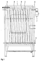
- FIGS. 1 to 3 show, there are two in one damper 1 Roller pairs, each with an upper guide roller 2, 3 and one lower pulley 4, 5 arranged side by side.
- the upper pulleys 2 and 3 are each freely rotatable arranged an axis 6, each of a rotatable Drive 7 is driven.
- the tension of the belt 8th measuring device 9 for example a dancer or Force measuring bearing control arranged, with the help of the speed of the following pair of rollers or their upper deflection roller 2 is controllable.
- each side of the strip By guiding the band 8 intersecting in the form of an eight each side of the strip alternately goes outside and inside, so that the tape is treated evenly.
- the damper is provided with direct steam injection, so that through an intermediate steam drying constant steam quality gets into the damper.
- the Damper can be used as an atmospheric damper, but also as a high-temperature damper be carried out so that both cotton, Polyamide, rayon and polyester tapes in this damper can be edited.
- the incoming band 8 becomes the upper pulley 3 fed, spirally over the upper Deflection roller and the lower deflection roller 5 to the other side the pulleys, then the tension of the belt measuring device 9 of the following second upper Deflection pulley 2 fed and then intersecting spirally up to the other end of the following pair of guide rollers helically guided.
Landscapes
- Engineering & Computer Science (AREA)
- Textile Engineering (AREA)
- Chemical & Material Sciences (AREA)
- Materials Engineering (AREA)
- Treatment Of Fiber Materials (AREA)
- Coloring (AREA)
Abstract
Description
Die Erfindung betrifft einen Dämpfer zum Behandeln, Färben, Appretieren, Waschen od. dgl. mindestens eines laufenden Bandes, bestehend aus mindestens einem Rollenpaar aus einer oberen und einer unteren Umlenkrolle, über die das Band schraubenlinienförmig geführt ist.The invention relates to a damper for treatment, dyeing, Finishing, washing or the like. At least one running belt, consisting of at least one pair of rollers from an upper and a lower pulley over which the belt is guided helically.
Ein derartiger Dämpfer ist aus dem Deutschen Patent 19 523 621 bekannt. Bei diesem Dämpfer laufen das Band oder die Bänder schraubenlinienförmig umlaufend über die untere und obere Rolle des jeweiligen Rollenpaares, so daß die eine Seite des Bandes oder der Bänder jeweils nach außen gerichtet ist, während die andere Seite des Bandes oder der Bänder stets zum Inneren des Dämpfers gerichtet ist.Such a damper is from German Patent 19 523 621 known. With this damper, the tape or tapes run spiraling around the lower and upper roller of the respective pair of rollers so that one side of the belt or the bands are directed outwards while the other side of the tape or tapes always to the inside of the Damper is directed.
Dabei stellt sich als nachteilig heraus, daß durch diese Bandführung das Band an der einen zum Inneren des Dämpfers gerichteten Seite unterschiedlich behandelt wird. Insbesondere können beim Färben Farbunterschiede zwischen den beiden Seiten des Bandes festgestellt werden. It turns out to be disadvantageous that this Band guide the band on one to the inside of the damper directed side is treated differently. In particular may have color differences between the two sides when dyeing of the tape can be determined.
Die Aufgabe der Erfindung besteht daher darin, einen Dämpfer der genannten Art vorzuschlagen, in dem die beiden Seiten des Bandes gleichmäßig behandelt werden.The object of the invention is therefore a damper to propose the kind mentioned in which the two sides of the Band are treated evenly.
Diese Aufgabe wird dadurch gelöst, daß das Band sich kreuzend in Form einer Acht über die sich in entgegengesetzter Richtung drehenden Umlenkrollen des Rollenpaares geführt ist.This object is achieved in that the tape crosses in the form of an eight over in the opposite direction rotating deflection rollers of the pair of rollers is guided.
Vorteilhaft sind die Umlenkrollen antreibbar. Bei einer vorteilhaften Ausführungsform hat mindestens eine Umlenkrolle des Dämpfer eine angetriebene Achse, auf der mehrere, einzelne einander benachbarte Walzenabschnitte frei drehbar angeordnet sind. Vorzugsweise ist die Antriebszahl der Achse der Umlenkrollen derart einstellbar, daß die Umfangsgeschwindigkeit bezogen auf die Außendurchmesser der Walzenabschnitte etwa gleich der Transportgeschwindigkeit des zu behandelnden Bandes ist.The deflection rollers can advantageously be driven. At a advantageous embodiment has at least one deflection roller the damper has a driven axle on which several, individual adjacent roller sections arranged freely rotatable are. Preferably, the number of drives of the axis is Deflection rollers adjustable so that the peripheral speed based on the outer diameter of the roller sections approximately equal to the transport speed of the belt to be treated is.
Vorteilhaft sind zwei Rollenpaare nebeneinander im Dämpfer angeordnet.Two pairs of rollers next to each other in the damper are advantageous arranged.
Vorzugsweise ist zwischen dem ersten und dem nachfolgenden zweiten Rollenpaar eine die Spannung des laufenden Bandes messende Vorrichtung zur Steuerung der Drehzahl des zweiten nachfolgenden Rollenpaares angeordnet.Is preferably between the first and the subsequent second pair of rollers the tension of the running belt measuring device for controlling the speed of the second subsequent roller pair arranged.
Vorzugsweise sind die Walzenabschnitte zylinderförmig mit gleichem Außendurchmesser ausgebildet. Bei einer weiteren vorteilhaften Ausführungsform sind die Walzenabschnitte kegelstumpfförmig ausgebildet, wobei die Randabschnitte benachbarter Walzenabschnitte den gleichen Außendurchmesser haben. The roller sections are preferably cylindrical with the same outside diameter. Another The roller sections are an advantageous embodiment frustoconical, the edge portions adjacent roller sections have the same outer diameter to have.
Vorzugsweise ist die Achsneigung mindestens einer der Umlenkrollen in Bezug zu anderen Umlenkrollen veränderbar.The axis inclination is preferably at least one of the Deflecting rollers can be changed in relation to other deflecting rollers.
Die Erfindung ist in den Zeichnungen beispielhaft dargestellt. Es zeigen:
- Fig. 1
- einen erfindungsgemäßen Dämpfer in Vorderansicht,
- Fig. 2
- den Dämpfer nach Fig. 1 in Seitenansicht und
- Fig. 3
- den Dämpfer in Draufsicht.
- Fig. 1
- a damper according to the invention in front view,
- Fig. 2
- 1 in side view and
- Fig. 3
- the damper in top view.
Wie die Figuren 1 bis 3 zeigen, sind in einem Dämpfer 1 zwei
Rollenpaare mit jeweils einer oberen Umlenkrolle 2, 3 und einer
unteren Umlenkrolle 4, 5 nebeneinander angeordnet.As FIGS. 1 to 3 show, there are two in one
Die oberen Umlenkrollen 2 und 3 sind jeweils frei drehbar auf
einer Achse 6 angeordnet, die jeweils von einem drehbaren
Antrieb 7 angetrieben ist.The
Wie insbesondere die Figuren 1 und 2 zeigen, ist über die
Rollenpaare ein Band 8 schraubenlinienförmig sich kreuzend in
Form einer Acht über die oberen Umlenkrollen 2 und 3 und die
sich in entgegengesetzter Richtung drehenden unteren
Umlenkrollen 4 und 5 geführt.As in particular Figures 1 and 2 show, is about
Pairs of rollers a
Wie insbesondere die Figur 2 zeigt, ist zwischen den
Rollenpaaren 2, 4, 3 und 5 eine die Spannung des Bandes 8
messende Vorrichtung 9, beispielsweise eine Tänzer- oder
Kraftmeßlagersteuerung angeordnet, mit deren Hilfe die Drehzahl
des nachfolgenden Rollenpaares bzw. deren oberer Umlenkrolle 2
steuerbar ist. As particularly shown in Figure 2, is between the
Durch die Führung des Bandes 8 sich kreuzend in Form einer Acht
gelangt jede Bandseite abwechselnd nach außen und innen, so daß
eine gleichmäßige Behandlung des Bandes erfolgt.By guiding the
Durch die Anordnung der die Spannung des Bandes 8 messenden
Vorrichtung 9 zwischen den Rollenpaaren und die damit bewirkte
Steuerung des nachfolgenden Rollenpaares hat die Bandware die
Möglichkeit, während des Durchlaufs durch den Dämpfer seine
Länge zu verändern, insbesondere zu schrumpfen.By the arrangement of the tension of the
Der Dämpfer wird mit Direkt-Dampfeinblasung versehen, so daß durch eine die zwischengeschaltete Dampftrocknung immer gleichbleibende Dampfqualität in den Dämpfer gelangt. Der Dämpfer kann als atmosphärischer Dämpfer, jedoch auch als Hoch-Temperatur-Dämpfer ausgeführt werden, so daß sowohl Baumwoll-, Polyamid-, Rayon- wie auch Polyesterbänder in diesem Dämpfer bearbeitet werden können.The damper is provided with direct steam injection, so that through an intermediate steam drying constant steam quality gets into the damper. The Damper can be used as an atmospheric damper, but also as a high-temperature damper be carried out so that both cotton, Polyamide, rayon and polyester tapes in this damper can be edited.
Wie die Figuren 2 und 3 zeigen, wird das zulaufende Band 8 der
oberen Umlenkrolle 3 zugeführt, spiralförmig über die obere
Umlenkrolle und die untere Umlenkrolle 5 bis zur anderen Seite
der Umlenkrollen geführt, dann über die die Spannung des Bandes
messende Vorrichtung 9 der nachfolgenden zweiten oberen
Umlenkrolle 2 zugeführt und dann spiralförmig sich kreuzend bis
zum anderen Ende des nachfolgenden Umlenkrollenpaares
schraubenlinienförmig geführt.As FIGS. 2 and 3 show, the
Es ist auch möglich, den Rollenpaaren mehrere Bänder gleichzeitig nebeneinander zuzuführen.It is also possible to have several pairs of rolls to feed at the same time.
Claims (9)
Rollenpaar (3, 5 und 2, 4) eine die Spannung des laufenden Bandes (8) messende Vorrichtung (9) zur Steuerung der Drehzahl des zweiten nachfolgenden Rollenpaares (2, 4) angeordnet ist. Damper according to claim 5, characterized in that between the first and the subsequent second
Roller pair (3, 5 and 2, 4) a device (9) measuring the tension of the running belt (8) for controlling the speed of the second subsequent roller pair (2, 4) is arranged.
Applications Claiming Priority (2)
| Application Number | Priority Date | Filing Date | Title |
|---|---|---|---|
| DE19860424A DE19860424C1 (en) | 1998-12-28 | 1998-12-28 | Steamer for processing fabric belts or ribbons has paired deflection rollers rotating in opposite directions for the fabric to follow a figure-of-eight path to give equal treatment to both sides |
| DE19860424 | 1998-12-28 |
Publications (3)
| Publication Number | Publication Date |
|---|---|
| EP1016748A2 true EP1016748A2 (en) | 2000-07-05 |
| EP1016748A3 EP1016748A3 (en) | 2001-01-24 |
| EP1016748B1 EP1016748B1 (en) | 2003-04-02 |
Family
ID=7892920
Family Applications (1)
| Application Number | Title | Priority Date | Filing Date |
|---|---|---|---|
| EP99123673A Expired - Lifetime EP1016748B1 (en) | 1998-12-28 | 1999-11-29 | Steaming device for treating, dyeing, finishing, washing or the like of at least one moving band |
Country Status (9)
| Country | Link |
|---|---|
| US (1) | US6364189B1 (en) |
| EP (1) | EP1016748B1 (en) |
| CN (1) | CN1099486C (en) |
| AT (1) | ATE236284T1 (en) |
| CZ (1) | CZ297909B6 (en) |
| DE (2) | DE19860424C1 (en) |
| ES (1) | ES2193652T3 (en) |
| HK (1) | HK1025798A1 (en) |
| TW (1) | TW475017B (en) |
Cited By (1)
| Publication number | Priority date | Publication date | Assignee | Title |
|---|---|---|---|---|
| EP2135986A1 (en) * | 2008-06-18 | 2009-12-23 | MAGEBA Textilmaschinen GmbH & Co. KG | After-treatment steamer for belts |
Families Citing this family (12)
| Publication number | Priority date | Publication date | Assignee | Title |
|---|---|---|---|---|
| DE10306730B3 (en) * | 2003-02-17 | 2004-10-21 | Mageba Textilmaschinen Vertriebs-Gmbh | Device for treating, steaming, dyeing, finishing, washing or the like. at least one circulating belt |
| DE102004041706A1 (en) * | 2004-05-17 | 2005-12-15 | Mageba-Textilmaschinen Vertriebs Gmbh | Single band treatment device for ligaments |
| US7398660B2 (en) * | 2005-09-14 | 2008-07-15 | Zzakey Technologies Ltd | Dyeing apparatus and method therefor |
| CN100570038C (en) * | 2008-04-01 | 2009-12-16 | 广州建峰特纺五金制造有限公司 | Woven tape dyeing machine |
| DE102011000010A1 (en) * | 2011-01-03 | 2012-07-05 | Mageba Textilmaschinen Gmbh & Co. Kg | Belt treatment device and method for thermosetting and stretching ribbons |
| EP2676908A1 (en) * | 2012-06-21 | 2013-12-25 | Texco Hook & Eye Tape Ltd | Apparatus for processing a fabric tape |
| CN103572531A (en) * | 2013-10-31 | 2014-02-12 | 吴江永固纺配有限公司 | Efficient textile cleaning device |
| CN103625963B (en) * | 2013-11-20 | 2016-02-17 | 江苏海狮机械集团有限公司 | Rolling device assisted by bed clothes |
| CN104195768B (en) * | 2014-05-23 | 2016-04-20 | 江苏双盈纺织科技有限公司 | A kind of spiral dyestuff formula yarn dyeing and printing device |
| CN105019164A (en) * | 2015-07-31 | 2015-11-04 | 湖州南浔中兴丝织有限公司 | Refining device for silk fabrics |
| CN109267265B (en) * | 2018-11-08 | 2020-12-04 | 宣城良知知识产权服务有限公司 | A raw materials cleaning equipment for textile processing |
| CN114960078A (en) * | 2022-07-16 | 2022-08-30 | 罗秀芝 | Polyester preparation process |
Citations (2)
| Publication number | Priority date | Publication date | Assignee | Title |
|---|---|---|---|---|
| DE4301529C1 (en) * | 1993-01-21 | 1994-03-17 | Stang Hans Peter | Textile finishing machinery - has free running rollers on driven shaft to transport textile material |
| DE19523621A1 (en) * | 1995-06-29 | 1997-01-02 | Stang Hans Peter | Narrow textile ribbon material economic wet treatment assembly |
Family Cites Families (7)
| Publication number | Priority date | Publication date | Assignee | Title |
|---|---|---|---|---|
| US2169061A (en) * | 1938-05-02 | 1939-08-08 | Warner Bros | Continuous-film-treating apparatus |
| NL88167C (en) * | 1953-08-17 | |||
| US2810572A (en) * | 1955-06-02 | 1957-10-22 | Devel O Pill Corp | Film processing apparatus |
| DE2029044C3 (en) * | 1970-06-12 | 1974-02-21 | Agfa-Gevaert Ag, 5090 Leverkusen | Photographic developing device |
| US3827617A (en) * | 1973-04-16 | 1974-08-06 | Eastman Kodak Co | Helical web path processing device utilizing force counter-acting spools |
| JPH089374B2 (en) * | 1990-03-13 | 1996-01-31 | 株式会社村田製作所 | Taping automatic sorter |
| JPH05317828A (en) * | 1992-05-15 | 1993-12-03 | Yoshida Kogyo Kk <Ykk> | Treatment of band-shaped object and its device |
-
1998
- 1998-12-28 DE DE19860424A patent/DE19860424C1/en not_active Expired - Fee Related
-
1999
- 1999-11-29 DE DE59904835T patent/DE59904835D1/en not_active Expired - Lifetime
- 1999-11-29 AT AT99123673T patent/ATE236284T1/en not_active IP Right Cessation
- 1999-11-29 EP EP99123673A patent/EP1016748B1/en not_active Expired - Lifetime
- 1999-11-29 ES ES99123673T patent/ES2193652T3/en not_active Expired - Lifetime
- 1999-12-07 TW TW088121344A patent/TW475017B/en not_active IP Right Cessation
- 1999-12-10 CN CN99126115A patent/CN1099486C/en not_active Expired - Fee Related
- 1999-12-14 CZ CZ0455099A patent/CZ297909B6/en not_active IP Right Cessation
- 1999-12-28 US US09/473,806 patent/US6364189B1/en not_active Expired - Fee Related
-
2000
- 2000-08-10 HK HK00104988A patent/HK1025798A1/en not_active IP Right Cessation
Patent Citations (2)
| Publication number | Priority date | Publication date | Assignee | Title |
|---|---|---|---|---|
| DE4301529C1 (en) * | 1993-01-21 | 1994-03-17 | Stang Hans Peter | Textile finishing machinery - has free running rollers on driven shaft to transport textile material |
| DE19523621A1 (en) * | 1995-06-29 | 1997-01-02 | Stang Hans Peter | Narrow textile ribbon material economic wet treatment assembly |
Cited By (1)
| Publication number | Priority date | Publication date | Assignee | Title |
|---|---|---|---|---|
| EP2135986A1 (en) * | 2008-06-18 | 2009-12-23 | MAGEBA Textilmaschinen GmbH & Co. KG | After-treatment steamer for belts |
Also Published As
| Publication number | Publication date |
|---|---|
| CZ455099A3 (en) | 2000-07-12 |
| CN1099486C (en) | 2003-01-22 |
| CN1258772A (en) | 2000-07-05 |
| ATE236284T1 (en) | 2003-04-15 |
| ES2193652T3 (en) | 2003-11-01 |
| HK1025798A1 (en) | 2000-11-24 |
| TW475017B (en) | 2002-02-01 |
| CZ297909B6 (en) | 2007-04-25 |
| EP1016748B1 (en) | 2003-04-02 |
| DE19860424C1 (en) | 2000-03-16 |
| US6364189B1 (en) | 2002-04-02 |
| EP1016748A3 (en) | 2001-01-24 |
| DE59904835D1 (en) | 2003-05-08 |
Similar Documents
| Publication | Publication Date | Title |
|---|---|---|
| EP1016748B1 (en) | Steaming device for treating, dyeing, finishing, washing or the like of at least one moving band | |
| DE2213881A1 (en) | FRICTION FALSE TWIST DEVICE | |
| DE1925315A1 (en) | Method and apparatus for treating yarn | |
| DE3028316C2 (en) | Device for reducing the tensile force of a thread which emerges from the twisting spindle of a two-for-one twisting machine with the formation of a thread balloon and is intended for the manufacture of a dye package | |
| DE4301529C1 (en) | Textile finishing machinery - has free running rollers on driven shaft to transport textile material | |
| DE3545270C1 (en) | Spreader | |
| DE3321802A1 (en) | DEVICE FOR SUCTIONING FIBER-SHAPED MATERIAL ON A BALE OPENER | |
| DE2238485A1 (en) | METHOD AND DEVICE FOR CONTINUOUS PRODUCTION OF WIRE ROPE | |
| DE102013108096A1 (en) | Spinning machine and false twisting device | |
| EP1447467A2 (en) | Device for treating, steaming, dyeing, finishing, washing or the like of at least one circulating band | |
| DE1435526A1 (en) | Method and device for false twisting | |
| DE4229825C2 (en) | Dryer for wide textile webs | |
| DE2526107A1 (en) | METHOD AND APPARATUS FOR MANUFACTURING TWISTED YARN AND YARN MANUFACTURED BY THE METHOD | |
| DE19523621A1 (en) | Narrow textile ribbon material economic wet treatment assembly | |
| DE9300761U1 (en) | Device for shrinking, stretching, dyeing, feeding or the like of running ribbons, threads or the like. | |
| DE2619954A1 (en) | PROCESS AND DEVICE FOR CONTINUOUS TREATMENT OF A STRIP OR WIRE-SHAPED MATERIAL | |
| DE1951625A1 (en) | Tricot fabric drying plant | |
| DE3050609C2 (en) | Device for drying a veneer sheet | |
| DE2242890A1 (en) | METHOD AND APPARATUS FOR MAKING BOWS IN A TREATMENT ROOM, SUCH AS A HANGING DAMPER | |
| DE69302976T2 (en) | Device for the continuous treatment of a band-shaped material | |
| DE2932074A1 (en) | FRICTION WRAPPER | |
| DE1477961A1 (en) | Device for surface treatment of wire or tape-shaped material | |
| WO2004057085A1 (en) | Installation for the treatment of a textile band, especially an elastic textile band | |
| DE19613177A1 (en) | Cooling and loosening of yarn plug from jet texturing stuffer box | |
| DE102005027730B3 (en) | Method for removing creases from tubular knitted ware containing natural and synthetic fibers comprises feeding it through stretcher where it is stretched radially until creases are invisible and treated with pressurized saturated steam |
Legal Events
| Date | Code | Title | Description |
|---|---|---|---|
| PUAI | Public reference made under article 153(3) epc to a published international application that has entered the european phase |
Free format text: ORIGINAL CODE: 0009012 |
|
| AK | Designated contracting states |
Kind code of ref document: A2 Designated state(s): AT BE CH CY DE DK ES FI FR GB GR IE IT LI LU MC NL PT SE |
|
| AX | Request for extension of the european patent |
Free format text: AL;LT;LV;MK;RO;SI |
|
| 17P | Request for examination filed |
Effective date: 20000904 |
|
| PUAL | Search report despatched |
Free format text: ORIGINAL CODE: 0009013 |
|
| AK | Designated contracting states |
Kind code of ref document: A3 Designated state(s): AT BE CH CY DE DK ES FI FR GB GR IE IT LI LU MC NL PT SE |
|
| AX | Request for extension of the european patent |
Free format text: AL;LT;LV;MK;RO;SI |
|
| AKX | Designation fees paid |
Free format text: AT BE CH CY DE DK ES FI FR GB GR IE IT LI LU MC NL PT SE |
|
| GRAH | Despatch of communication of intention to grant a patent |
Free format text: ORIGINAL CODE: EPIDOS IGRA |
|
| GRAH | Despatch of communication of intention to grant a patent |
Free format text: ORIGINAL CODE: EPIDOS IGRA |
|
| GRAA | (expected) grant |
Free format text: ORIGINAL CODE: 0009210 |
|
| AK | Designated contracting states |
Designated state(s): AT BE CH CY DE DK ES FI FR GB GR IE IT LI LU MC NL PT SE |
|
| PG25 | Lapsed in a contracting state [announced via postgrant information from national office to epo] |
Ref country code: NL Free format text: LAPSE BECAUSE OF FAILURE TO SUBMIT A TRANSLATION OF THE DESCRIPTION OR TO PAY THE FEE WITHIN THE PRESCRIBED TIME-LIMIT Effective date: 20030402 Ref country code: IE Free format text: LAPSE BECAUSE OF NON-PAYMENT OF DUE FEES Effective date: 20030402 Ref country code: FI Free format text: LAPSE BECAUSE OF FAILURE TO SUBMIT A TRANSLATION OF THE DESCRIPTION OR TO PAY THE FEE WITHIN THE PRESCRIBED TIME-LIMIT Effective date: 20030402 |
|
| REG | Reference to a national code |
Ref country code: GB Ref legal event code: FG4D Free format text: NOT ENGLISH |
|
| REG | Reference to a national code |
Ref country code: CH Ref legal event code: EP |
|
| REG | Reference to a national code |
Ref country code: IE Ref legal event code: FG4D Free format text: GERMAN |
|
| REF | Corresponds to: |
Ref document number: 59904835 Country of ref document: DE Date of ref document: 20030508 Kind code of ref document: P |
|
| GBT | Gb: translation of ep patent filed (gb section 77(6)(a)/1977) | ||
| PG25 | Lapsed in a contracting state [announced via postgrant information from national office to epo] |
Ref country code: SE Free format text: LAPSE BECAUSE OF FAILURE TO SUBMIT A TRANSLATION OF THE DESCRIPTION OR TO PAY THE FEE WITHIN THE PRESCRIBED TIME-LIMIT Effective date: 20030702 Ref country code: PT Free format text: LAPSE BECAUSE OF FAILURE TO SUBMIT A TRANSLATION OF THE DESCRIPTION OR TO PAY THE FEE WITHIN THE PRESCRIBED TIME-LIMIT Effective date: 20030702 Ref country code: GR Free format text: LAPSE BECAUSE OF FAILURE TO SUBMIT A TRANSLATION OF THE DESCRIPTION OR TO PAY THE FEE WITHIN THE PRESCRIBED TIME-LIMIT Effective date: 20030702 Ref country code: DK Free format text: LAPSE BECAUSE OF FAILURE TO SUBMIT A TRANSLATION OF THE DESCRIPTION OR TO PAY THE FEE WITHIN THE PRESCRIBED TIME-LIMIT Effective date: 20030702 |
|
| NLV1 | Nl: lapsed or annulled due to failure to fulfill the requirements of art. 29p and 29m of the patents act | ||
| REG | Reference to a national code |
Ref country code: ES Ref legal event code: FG2A Ref document number: 2193652 Country of ref document: ES Kind code of ref document: T3 |
|
| REG | Reference to a national code |
Ref country code: IE Ref legal event code: FD4D Ref document number: 1016748E Country of ref document: IE |
|
| PG25 | Lapsed in a contracting state [announced via postgrant information from national office to epo] |
Ref country code: LU Free format text: LAPSE BECAUSE OF NON-PAYMENT OF DUE FEES Effective date: 20031129 Ref country code: CY Free format text: LAPSE BECAUSE OF FAILURE TO SUBMIT A TRANSLATION OF THE DESCRIPTION OR TO PAY THE FEE WITHIN THE PRESCRIBED TIME-LIMIT Effective date: 20031129 |
|
| PG25 | Lapsed in a contracting state [announced via postgrant information from national office to epo] |
Ref country code: MC Free format text: LAPSE BECAUSE OF NON-PAYMENT OF DUE FEES Effective date: 20031130 |
|
| ET | Fr: translation filed | ||
| PLBE | No opposition filed within time limit |
Free format text: ORIGINAL CODE: 0009261 |
|
| STAA | Information on the status of an ep patent application or granted ep patent |
Free format text: STATUS: NO OPPOSITION FILED WITHIN TIME LIMIT |
|
| 26N | No opposition filed |
Effective date: 20040105 |
|
| PGFP | Annual fee paid to national office [announced via postgrant information from national office to epo] |
Ref country code: BE Payment date: 20041118 Year of fee payment: 6 |
|
| PGFP | Annual fee paid to national office [announced via postgrant information from national office to epo] |
Ref country code: AT Payment date: 20041122 Year of fee payment: 6 |
|
| PGFP | Annual fee paid to national office [announced via postgrant information from national office to epo] |
Ref country code: ES Payment date: 20041126 Year of fee payment: 6 |
|
| PGFP | Annual fee paid to national office [announced via postgrant information from national office to epo] |
Ref country code: FR Payment date: 20051117 Year of fee payment: 7 |
|
| PG25 | Lapsed in a contracting state [announced via postgrant information from national office to epo] |
Ref country code: AT Free format text: LAPSE BECAUSE OF NON-PAYMENT OF DUE FEES Effective date: 20051129 |
|
| PG25 | Lapsed in a contracting state [announced via postgrant information from national office to epo] |
Ref country code: ES Free format text: LAPSE BECAUSE OF NON-PAYMENT OF DUE FEES Effective date: 20051130 Ref country code: BE Free format text: LAPSE BECAUSE OF NON-PAYMENT OF DUE FEES Effective date: 20051130 |
|
| REG | Reference to a national code |
Ref country code: ES Ref legal event code: FD2A Effective date: 20051130 |
|
| REG | Reference to a national code |
Ref country code: FR Ref legal event code: ST Effective date: 20070731 |
|
| BERE | Be: lapsed |
Owner name: *MAGEBA TEXTILMASCHINEN G.M.B.H. + CO. Effective date: 20051130 |
|
| PG25 | Lapsed in a contracting state [announced via postgrant information from national office to epo] |
Ref country code: FR Free format text: LAPSE BECAUSE OF NON-PAYMENT OF DUE FEES Effective date: 20061130 |
|
| PGFP | Annual fee paid to national office [announced via postgrant information from national office to epo] |
Ref country code: GB Payment date: 20101029 Year of fee payment: 12 |
|
| GBPC | Gb: european patent ceased through non-payment of renewal fee |
Effective date: 20111129 |
|
| PG25 | Lapsed in a contracting state [announced via postgrant information from national office to epo] |
Ref country code: GB Free format text: LAPSE BECAUSE OF NON-PAYMENT OF DUE FEES Effective date: 20111129 |
|
| PGFP | Annual fee paid to national office [announced via postgrant information from national office to epo] |
Ref country code: DE Payment date: 20121015 Year of fee payment: 14 Ref country code: CH Payment date: 20121018 Year of fee payment: 14 |
|
| PGFP | Annual fee paid to national office [announced via postgrant information from national office to epo] |
Ref country code: IT Payment date: 20121025 Year of fee payment: 14 |
|
| REG | Reference to a national code |
Ref country code: CH Ref legal event code: PL |
|
| PG25 | Lapsed in a contracting state [announced via postgrant information from national office to epo] |
Ref country code: LI Free format text: LAPSE BECAUSE OF NON-PAYMENT OF DUE FEES Effective date: 20131130 Ref country code: CH Free format text: LAPSE BECAUSE OF NON-PAYMENT OF DUE FEES Effective date: 20131130 |
|
| REG | Reference to a national code |
Ref country code: DE Ref legal event code: R119 Ref document number: 59904835 Country of ref document: DE Effective date: 20140603 |
|
| PG25 | Lapsed in a contracting state [announced via postgrant information from national office to epo] |
Ref country code: IT Free format text: LAPSE BECAUSE OF NON-PAYMENT OF DUE FEES Effective date: 20131129 Ref country code: DE Free format text: LAPSE BECAUSE OF NON-PAYMENT OF DUE FEES Effective date: 20140603 |