EP1016320B1 - Method and apparatus for encoding and decoding multiple audio channels at low bit rates - Google Patents
Method and apparatus for encoding and decoding multiple audio channels at low bit rates Download PDFInfo
- Publication number
- EP1016320B1 EP1016320B1 EP98931197A EP98931197A EP1016320B1 EP 1016320 B1 EP1016320 B1 EP 1016320B1 EP 98931197 A EP98931197 A EP 98931197A EP 98931197 A EP98931197 A EP 98931197A EP 1016320 B1 EP1016320 B1 EP 1016320B1
- Authority
- EP
- European Patent Office
- Prior art keywords
- signal
- signals
- subband
- spatial
- composite
- Prior art date
- Legal status (The legal status is an assumption and is not a legal conclusion. Google has not performed a legal analysis and makes no representation as to the accuracy of the status listed.)
- Expired - Lifetime
Links
- 238000000034 method Methods 0.000 title claims description 64
- 239000002131 composite material Substances 0.000 claims abstract description 112
- 230000004044 response Effects 0.000 claims abstract description 33
- 230000002123 temporal effect Effects 0.000 claims abstract description 27
- 230000003595 spectral effect Effects 0.000 claims abstract description 24
- 230000008859 change Effects 0.000 claims description 24
- 230000000873 masking effect Effects 0.000 claims description 21
- 230000000875 corresponding effect Effects 0.000 claims description 18
- 230000007423 decrease Effects 0.000 claims description 12
- 230000002596 correlated effect Effects 0.000 claims description 5
- 238000013507 mapping Methods 0.000 claims 8
- 230000003247 decreasing effect Effects 0.000 claims 6
- 239000006185 dispersion Substances 0.000 claims 2
- 238000009499 grossing Methods 0.000 abstract description 15
- 239000013598 vector Substances 0.000 description 14
- 230000000694 effects Effects 0.000 description 13
- 238000013144 data compression Methods 0.000 description 12
- 238000007906 compression Methods 0.000 description 10
- 230000006835 compression Effects 0.000 description 10
- 230000000295 complement effect Effects 0.000 description 8
- 238000001914 filtration Methods 0.000 description 8
- 230000005236 sound signal Effects 0.000 description 8
- 238000009795 derivation Methods 0.000 description 6
- 230000001052 transient effect Effects 0.000 description 5
- 230000015572 biosynthetic process Effects 0.000 description 4
- 238000004891 communication Methods 0.000 description 4
- 238000010586 diagram Methods 0.000 description 4
- 230000009467 reduction Effects 0.000 description 4
- 238000001228 spectrum Methods 0.000 description 4
- 238000003786 synthesis reaction Methods 0.000 description 4
- 230000003466 anti-cipated effect Effects 0.000 description 3
- ZYXYTGQFPZEUFX-UHFFFAOYSA-N benzpyrimoxan Chemical compound O1C(OCCC1)C=1C(=NC=NC=1)OCC1=CC=C(C=C1)C(F)(F)F ZYXYTGQFPZEUFX-UHFFFAOYSA-N 0.000 description 3
- 230000005540 biological transmission Effects 0.000 description 3
- 230000008569 process Effects 0.000 description 3
- 230000009466 transformation Effects 0.000 description 3
- 241000255925 Diptera Species 0.000 description 2
- 230000003044 adaptive effect Effects 0.000 description 2
- 230000015556 catabolic process Effects 0.000 description 2
- 238000006731 degradation reaction Methods 0.000 description 2
- 239000000284 extract Substances 0.000 description 2
- 230000007274 generation of a signal involved in cell-cell signaling Effects 0.000 description 2
- 239000011159 matrix material Substances 0.000 description 2
- 238000013139 quantization Methods 0.000 description 2
- 238000011084 recovery Methods 0.000 description 2
- 230000006978 adaptation Effects 0.000 description 1
- 230000008901 benefit Effects 0.000 description 1
- 230000001276 controlling effect Effects 0.000 description 1
- 230000006837 decompression Effects 0.000 description 1
- 230000006735 deficit Effects 0.000 description 1
- 230000000593 degrading effect Effects 0.000 description 1
- 230000005284 excitation Effects 0.000 description 1
- 238000010237 hybrid technique Methods 0.000 description 1
- 238000010606 normalization Methods 0.000 description 1
- 230000008520 organization Effects 0.000 description 1
- 238000005070 sampling Methods 0.000 description 1
Images


Classifications
-
- H—ELECTRICITY
- H04—ELECTRIC COMMUNICATION TECHNIQUE
- H04S—STEREOPHONIC SYSTEMS
- H04S3/00—Systems employing more than two channels, e.g. quadraphonic
-
- H—ELECTRICITY
- H04—ELECTRIC COMMUNICATION TECHNIQUE
- H04H—BROADCAST COMMUNICATION
- H04H20/00—Arrangements for broadcast or for distribution combined with broadcast
- H04H20/86—Arrangements characterised by the broadcast information itself
- H04H20/88—Stereophonic broadcast systems
-
- G—PHYSICS
- G10—MUSICAL INSTRUMENTS; ACOUSTICS
- G10L—SPEECH ANALYSIS TECHNIQUES OR SPEECH SYNTHESIS; SPEECH RECOGNITION; SPEECH OR VOICE PROCESSING TECHNIQUES; SPEECH OR AUDIO CODING OR DECODING
- G10L19/00—Speech or audio signals analysis-synthesis techniques for redundancy reduction, e.g. in vocoders; Coding or decoding of speech or audio signals, using source filter models or psychoacoustic analysis
- G10L19/008—Multichannel audio signal coding or decoding using interchannel correlation to reduce redundancy, e.g. joint-stereo, intensity-coding or matrixing
-
- G—PHYSICS
- G10—MUSICAL INSTRUMENTS; ACOUSTICS
- G10L—SPEECH ANALYSIS TECHNIQUES OR SPEECH SYNTHESIS; SPEECH RECOGNITION; SPEECH OR VOICE PROCESSING TECHNIQUES; SPEECH OR AUDIO CODING OR DECODING
- G10L19/00—Speech or audio signals analysis-synthesis techniques for redundancy reduction, e.g. in vocoders; Coding or decoding of speech or audio signals, using source filter models or psychoacoustic analysis
- G10L19/02—Speech or audio signals analysis-synthesis techniques for redundancy reduction, e.g. in vocoders; Coding or decoding of speech or audio signals, using source filter models or psychoacoustic analysis using spectral analysis, e.g. transform vocoders or subband vocoders
- G10L19/0204—Speech or audio signals analysis-synthesis techniques for redundancy reduction, e.g. in vocoders; Coding or decoding of speech or audio signals, using source filter models or psychoacoustic analysis using spectral analysis, e.g. transform vocoders or subband vocoders using subband decomposition
- G10L19/0208—Subband vocoders
-
- H—ELECTRICITY
- H04—ELECTRIC COMMUNICATION TECHNIQUE
- H04B—TRANSMISSION
- H04B1/00—Details of transmission systems, not covered by a single one of groups H04B3/00 - H04B13/00; Details of transmission systems not characterised by the medium used for transmission
- H04B1/66—Details of transmission systems, not covered by a single one of groups H04B3/00 - H04B13/00; Details of transmission systems not characterised by the medium used for transmission for reducing bandwidth of signals; for improving efficiency of transmission
- H04B1/665—Details of transmission systems, not covered by a single one of groups H04B3/00 - H04B13/00; Details of transmission systems not characterised by the medium used for transmission for reducing bandwidth of signals; for improving efficiency of transmission using psychoacoustic properties of the ear, e.g. masking effect
-
- H—ELECTRICITY
- H04—ELECTRIC COMMUNICATION TECHNIQUE
- H04R—LOUDSPEAKERS, MICROPHONES, GRAMOPHONE PICK-UPS OR LIKE ACOUSTIC ELECTROMECHANICAL TRANSDUCERS; DEAF-AID SETS; PUBLIC ADDRESS SYSTEMS
- H04R5/00—Stereophonic arrangements
- H04R5/04—Circuit arrangements, e.g. for selective connection of amplifier inputs/outputs to loudspeakers, for loudspeaker detection, or for adaptation of settings to personal preferences or hearing impairments
-
- H—ELECTRICITY
- H04—ELECTRIC COMMUNICATION TECHNIQUE
- H04S—STEREOPHONIC SYSTEMS
- H04S2420/00—Techniques used stereophonic systems covered by H04S but not provided for in its groups
- H04S2420/03—Application of parametric coding in stereophonic audio systems
Definitions
- the present invention relates generally to the high-quality encoding and decoding of multiple channels of audio information to reduce the information requirements of signals that convey the audio information.
- the present invention is useful in conveying in real time multiple channels of audio information over relatively low-bandwidth transmission paths such as the telephone lines typically used to connect a personal computer with public networks.
- Information capacity requirements can be reduced by applying either or both of two data compression techniques.
- One type sometimes referred to as “lossy” compression, reduces information capacity requirements in a manner which does not assure, and generally prevents, perfect recovery of the original signal.
- Another type sometimes referred to as “lossless” compression, reduces information capacity requirements in a manner that permits perfect recovery of the original signal.
- Quantization is one well known lossy compression technique. Quantization can reduce information capacity requirements by reducing the number of bits used to represent each sample of a digital signal, thereby reducing the accuracy of the digital signal representation. In audio coding applications, the reduced accuracy or quantizing error is manifested as quantizing noise. If the errors are of sufficient magnitude, the quantizing noise will degrade the subjective quality of the coded signal.
- Various audio coding techniques attempt to apply lossy compression techniques to an input signal without suffering any perceptible degradation by removing components of information which are imperceptible or irrelevant to perceived coding quality.
- a complementary decoding technique can recover a replica of the input signal which is perceptually indistinguishable from the input signal provided the removed component is truly irrelevant.
- split-band encoding splits an input signal into several narrow-band signals and adaptively quantizes each narrow-band signal according to psychoacoustic principles.
- Psychoacoustic principles are based on the frequency-analysis properties of the human auditory system that resemble highly asymmetrical tuned filters having variable center frequencies and bandwidths that vary as a function of the center frequency.
- the ability of the human auditory system to detect distinct tones generally increases as the difference in frequency between the tones increases; however, the resolving ability of the human auditory system remains substantially constant for frequency differences less than the bandwidth of the filtering behavior mentioned above.
- This bandwidth varies throughout the audio spectrum and is referred to as a "critical bandwidth.”
- a dominant signal is more likely to mask the audibility of other signals anywhere within a critical bandwidth than it is likely to mask other signals at frequencies outside that critical bandwidth.
- a dominant signal may mask other signals which occur not only at the same time as the masking signal, but also which occur before and after the masking signal.
- the duration of pre- and postmasking effects depend upon the magnitude of the masking signal, but premasking effects are usually of much shorter duration than postmasking effects.
- the premasking interval can extend beyond 100 msec. but is generally regarded to be limited to less than 5 msec.
- the postmasking interval can extend beyond 500 msec. but is generally regarded to be limited to about 50 msec.
- a masked component of a signal is irrelevant and can be removed without changing the perceptual experience of a human listener.
- Split-band audio encoding often comprises using a forward or "analysis" filter bank to divide an audio signal bandwidth into several subband signals each having a bandwidth commensurate with the critical bandwidths of the human auditory system. Each subband signal is quantized using just enough bits to ensure that the quantizing noise in each subband is masked by the spectral component in that subband and possibly adjacent subbands.
- Split-band audio decoding comprises reconstructing a replica of the original signal using an inverse or "synthesis" filter bank. If the bandwidths of the filters in the filter banks and the quantizing accuracy of the subband signals are chosen properly, the reconstructed replica can be perceptually indistinguishable from the original signal.
- Subband coding may use various analog and/or digital filtering techniques to implement the filter banks.
- Transform coding uses various time-domain to frequency-domain transforms to implement the filter banks. Adjacent frequency-domain transform coefficients may be grouped to define "subbands" having effective bandwidths which are sums of individual transform coefficient bandwidths.
- split-band coding refers to subband encoding and decoding, transform encoding and decoding, and other encoding and decoding techniques which operate upon portions of the useful signal bandwidth.
- subband refers to these portions of the useful signal bandwidth, whether implemented by a true subband coder, a transform coder, or other technique.
- subband signal refers to a split-band filtered signal representation within a respective subband.
- Lossy compression may include scaling.
- Many coding techniques including split-band coding convey signals using a scaled representation to extend the dynamic range of encoded information represented by a limited number of bits.
- a scaled representation comprises one or more "scaling factors" associated with “scaled values” corresponding to elements of the encoded signals.
- Many forms of scaled representation are known. By sacrificing some accuracy in the scaled values, even fewer bits may be used to convey information using a "block-scaled representation.”
- a block-scaled representation comprises a group or block of scaled values associated with a common scaling factor.
- a lossless type of compression reduces information capacity requirements without degradation by reducing or eliminating components of the signal which are redundant.
- a complementary decompression technique can recover the original signal perfectly by providing the redundant component removed during compression.
- Examples of lossless compression techniques include run-length encoding, differential coding, linear predictive coding, and transform coding. Variations, combinations and adaptive forms of these compression techniques are also known.
- Hybrid techniques combining lossless and lossy compression techniques are also known. For example, split-band coding using a transform-based filter bank combines lossless transform coding with lossy psychoacoustic perceptual coding.
- Single-channel coding techniques such as those discussed above do not provide a sufficient reduction in information requirements to permit multiple channels of high-quality audio to be conveyed over low-bandwidth paths, e.g., conventional telephone lines, for real-time playback.
- Various high-performance coding systems require on the order of 64 k-bits per second or more to convey in real time audio signals having a bandwidth of 15 kHz. Because multiples of these bit rates are required to convey multiple audio channels, impossibly large improvements in the performance of single-channel coding systems are needed to allow multiple channels of audio to be conveyed in real time over limited-bandwidth communication paths such as conventional residential telephone lines.
- the needed additional reduction in information capacity requirements is addressed by multiple-channel coding techniques referred to herein as spatial coding techniques.
- One form of spatial coding combines multiple signals according to an encoding matrix and recovers a replica of the original signals using a complementary decoding matrix.
- Many 4:2:4 matrixing techniques are known that combine four signals into two signals for transmission or storage and subsequently recover a replica of the four original signals from the two encoded signals.
- This coding technique suffers from high levels of crosstalk between signals.
- a number of adaptive matrixing techniques have been developed to reduce the level of crosstalk but neither the reduction in crosstalk nor the reduction in information capacity requirements is sufficient.
- Another form of spatial coding splits multiple input signals into subband signals, generates a vector of steering information representing spectral levels of the channels in each subband, combines the subband signals for all channels in a given frequency subband to produce a summation or composite subband signal, perceptually encodes the composite subband signals, and assembles the encoded composite subband signals and the steering vectors into an encoded signal.
- a complementary decoder generates a subband signal in a respective frequency subband for each output signal by scaling the appropriate composite subband signal according to the steering vector for that subband, and generates an output signal by passing the scaled subband signals through an inverse filter bank.
- an encoder generates a plurality of channel subband signals from a plurality of input signals in a plurality of frequency subbands, generates a composite signal representing at least a portion of the bandwidth of the input signals, generates a spatial-characteristic signal representing spatial characteristics of a soundfield in response to respective channel subband signals in a frequency subband, the spatial-characteristic signal conveying information representing signal levels of the respective channel subband signals such that decreases in values of the information representing the signal levels are limited to be commensurate with decreases in temporal post-masking characteristics of a human auditory system, and assembles the composite signal and the spatial-characteristics signal into an encoded signal.
- a decoder obtains from an encoded signal one or more composite signals and a plurality of spatial-characteristics signals, and derives a plurality of composite subband signals from the one or more composite signals, wherein each spatial-characteristics signal is associated with a respective composite subband signal and represents spatial characteristics of a respective soundfield corresponding to the respective composite subband signal, derives from the spatial-characteristics signals a plurality of gain factors, wherein decreases in values of the gain factors are limited to be commensurate with decreases in temporal post-masking characteristics of a human auditory system, and maps a respective composite subband signal into one or more interim subband signals according to a respective gain factor, and generates a plurality of output signals by applying one or more inverse filter banks to the interim subband signals.
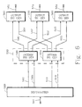
- Fig. 1 illustrates one embodiment of a multi-channel encoder according to the present invention.
- Subband signal generator 10 receives an input signal from path 1 and, in response to that input signal, generates channel subband signals along paths 11 and 12.
- subband signal generator 20 generates channel subband signals along paths 21 and 22 in response to an input signal received from path 2
- subband signal generator 30 generates channel subband signals along paths 31 and 32 in response to an input signal received from path 3.
- more than two channel subband signals are generated by each subband signal generator.
- each subband signal generator will generate channel subband signals representing frequency subbands that span the useful bandwidth of each input signal; however, this is not required to practice the present invention.
- one or more subband signal generators may generate channel subband signals that represent only a portion of the useful bandwidth, say only the portion of the bandwidth below about 1.5 kHz.
- channel subband signals should be generated for all input signals in that portion of the spectrum that will be analyzed by spatial coder 40 to determine soundfield spatial characteristics.
- Spatial coder 40 generates spatial-characteristic signals along paths 41 and 42 in response to the channel subband signals received from the subband signal generators. Each of these spatial-characteristic signals represents the spatial characteristic of a soundfield that corresponds to one or more channel subband signals in a respective frequency subband.
- Composite signal generator 60 generates a composite signal along path 61 by combining the input signals received from paths 1, 2 and 3.
- data compression is not required to practice the present invention. If data compression is used, essentially any form of data compression may be applied to the composite signal generated along path 61.
- Formatter 50 assembles the spatial-characteristic signals received from paths 41 and 42 and the composite signal received from path 61 into an output signal that is passed along path 51 for transmission or storage. If the composite signal is subjected to data compression or encoding, the encoded form is assembled into the output signal rather than the composite signal itself.
- Fig. 2 illustrates another embodiment of a multi-channel encoder according to the present invention. This embodiment is identical to the embodiment illustrated in Fig. 1 except for the addition of subband signal generator 70 which generates composite subband signals along paths 71 to 73 in response to the composite signal received from path 61.
- subband signal generator 70 which generates composite subband signals along paths 71 to 73 in response to the composite signal received from path 61.
- data compression may be applied to these composite subband signals.
- perceptual coding techniques may be applied to good advantage if the bandwidth of the composite subband signals is commensurate with the critical bandwidths. It should be pointed out that the bandwidths of the composite subband signals generated by subband signal generator 70 do not have to be the same as the bandwidths of the channel subband signals generated by subband signal generators 10, 20 and 30. Indeed, even the bandwidths of the channel subband signals generated by subband signal generators 10, 20 and 30 do not have to be the same.
- nonrecursive, recursive, or lattice filters may be used.
- Some nonrecursive filters may be implemented using polynomial filters or transforms. Examples of specific filter designs include various transforms such as the Discrete Fourier Transform (DFT) and Discrete Cosine Transform (DCT), the Quadrature Mirror Filter (QMF), and the so called evenly-stacked and oddly-stacked Time-Domain Aliasing Cancellation (TDAC) transforms.
- DFT Discrete Fourier Transform
- DCT Discrete Cosine Transform
- QMF Quadrature Mirror Filter
- TDAC Time-Domain Aliasing Cancellation
- subband signal generators 10, 20 and 30 preferably incorporate identical filter banks that are designed to optimize spectral resolution and which provide an accurate measure of subband signal power.
- the filter bank may be selected to optimize data compression by providing critical sampling and by balancing a tradeoff between spectral resolution and temporal resolution.
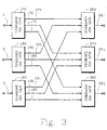
- Fig. 3 illustrates an embodiment of a composite signal generator that can be incorporated into an encoder such as that illustrated in Fig. 1.
- subband signal generator 170 generates subband signals along paths 171 to 173 in response to the input signal received from path 1.
- subband signal generator 180 generates subband signals along paths 181 to 183 in response to the input signal received from path 2
- subband signal generator 190 generates subband signals along paths 191 to 193 in response to the input signal received from path 3.
- Subband signal generator 260 generates composite subband signals along path 261 in response to the subband signals received from paths 171, 181 and 191.
- subband signal generator 270 generates a composite subband signal along path 271 in response to the subband signals received from paths 172, 182 and 192
- subband signal generator 280 generates a composite subband signal along path 281 in response to the subband signals received from paths 173, 183 and 193.
- subband signal generators 260, 270 and 280 generate the composite subband signals by forming a sum of the subband signals received from subband signal generators 170, 180 and 190.
- Alternative ways of forming composite subband signals are discussed below. The way in which the composite subband signals are generated is not critical to the practice of the present invention, and they may be subjected to some form of data compression.
- Fig. 4 illustrates another embodiment of a multi-channel encoder according to the present invention.
- This embodiment is identical to the embodiment illustrated in Fig. 1 except that composite signal generator 160 generates one or more composite signals along path 161 in response to the channel subband signals generated by subband signal generators 10, 20 and 30.
- composite signal generator 160 combines channel subband signals in a given frequency subband for each input signal to generate a composite subband signal for that frequency subband.
- the one or more composite signals generated along path 161 may be subjected to some form of data compression.
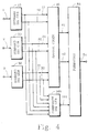
- Fig. 5 illustrates one embodiment of a multi-channel decoder according to the present invention.
- Deformatter 510 extracts one or more composite signals and spatial-characteristic signals from the encoded signal received from path 501.
- a composite signal is passed along path 511 and spatial-characteristic signals are passed along paths 515 and 516.
- Subband signal generator 520 generates composite subband signals along paths 521 and 522 in response to the composite signal received from path 511.
- Spatial decoder 530 derives a plurality of gain factors from the spatial-characteristics signals received from paths 515 and 516 and uses those gain factors to map the composite subband signals into one or more interim subband signals.
- Interim signal generator 540 generates interim subband signals along paths 541, 542 and 543
- interim signal generator 550 generates interim subband signals along paths 551, 552 and 553.
- Output signal generator 560 generates an output signal along path 561 in response to the interim subband signals received from paths 541 and 551.
- output signal generator 570 generates an output signal along path 571 in response to interim subband signals received from paths 542 and 552
- output signal generator 580 generates an output signal along path 581 in response to interim subband signals received from paths 543 and 553.
- each interim subband signal is mapped into all output signals; however, this is not necessary.
- a given interim subband signal need not be mapped into all output signals.
- a complementary form of data expansion may be applied as necessary to the signal passed along path 511 and/or to the subband signals passed along paths 521 and 522.
- subband signal generator 520 may be used to implement subband signal generator 520.
- a complementary or inverse technique is used to implement the output signal generators.
- Fig. 6 illustrates another embodiment of a multi-channel decoder according to the present invention.
- This embodiment is identical to the embodiment illustrated in Fig. 5 except that deformatter 510 extracts the composite subband signals directly from the encoded signal and passes those signals along paths 512 and 513. Data expansion may be applied to the composite subband signals as necessary.
- the inverse filtering or inverse transformation technique used to implement the output signal generators should be complementary to the filtering or transformation technique used to generate the composite subband signals that were assembled into the encoded signal.
- An encoder may generate spatial-characteristics signals in a first form and possibly an additional second form.
- a first form in one embodiment, referred to herein as a Type I signal represents some measure of signal level for each channel subband signal that contributes to the soundfield.
- the measure of signal level may be peak amplitude, average amplitude or root-mean-square (RMS), for example.
- the Type I signal represents some measure of signal level for each "virtual" channel subband signal that contributes to the soundfield.
- a virtual channel need not exist as a physical entity but may be a conceptual entity representing, for example, a weighted sum or other combination of signals from two or more physical channels.
- the essential aspect is that the number of elements in the spatial-characteristics signal need not be equal to the number of actual physical channels that contribute to the soundfield.
- a second form referred to herein as a Type II signal, represents one or more apparent directions for the soundfield and possibly some indication of soundfield width or dispersal characteristics about the directions.
- a direction may be represented by a vector in a three- or two-dimensional space, for example.
- a Type I spatial characteristics signal for a respective frequency subband comprises five measures of signal level, say power, a measure for each input channel in that frequency subband.
- a Type II spatial-characteristics signal for a respective frequency subband comprises a representation of one or more directions.
- the Type II signal for each subband could be expressed as a vector in Cartesian coordinates or polar coordinates for a two- or three-dimensional space.
- the information capacity requirements of the Type II signal is independent of the number of input channels; however, the process that generates this type of spatial-characteristics signal must be informed of the number and location for the sound source represented by each input channel so that the soundfield direction can be correctly determined.
- an encoder generates spatial-characteristics signals for a respective frequency subband in a first type and possibly an additional second type.
- the choice can be based on essentially any criterion such as required audio quality, output channel bandwidth and/or number of apparent directions.
- Type II signals might be used in multi-channel systems having lower channel bandwidths since fewer bits are generally needed to encode a Type II signal as opposed to the number of bits needed to encode a Type I signal. If the sound field for a respective subband is deemed to have a number of directions greater than some threshold number, however, a Type I signal might require fewer bits.
- the spatial-characteristics signals for the subband signals representing the orchestra could be formed in the first form and the spatial characteristics signals for the subband signals representing the mosquito could be formed in the second form.
- a Type I spatial-characteristics signal is generally preferred for a subband as the number of apparent directions for the soundfield in that subband increases. If only one channel has significant spectral energy in a frequency subband, the number of apparent directions for the soundfield in that subband is deemed to be one. The number of apparent directions is also deemed to be one if more than one channel has significant energy in a respective subband provided the amplitudes and phases of the channels in that subband are correlated so as to represent a single sound source.
- channel subband signals and spatial-characteristic signals does not need to be the same for every frequency subband. Furthermore, the relationship does not need to be fixed but can vary in response to various considerations such as input signal characteristics or output channel bandwidth.
- a respective spatial-characteristic signal is generated for each frequency subband and represents the spatial characteristics of a soundfield corresponding to all channel subband signals in that subband.
- the spatial-characteristic signal generated along path 41 represents the spatial characteristic of a soundfield corresponding to the channel subband signals received from paths 11, 21 and 31, and the spatial-characteristic signal generated along path 42 represents the spatial characteristic of a soundfield corresponding to the channel subband signals received from paths 12 and 32.
- another spatial-characteristic signal is generated to represent the spatial characteristics of a soundfield corresponding to the channel subband signal received from path 22.
- an encoder adaptively forms spatial-characteristic signals in a first form and possibly an additional second form described above.
- the adaptation can be based on the number of apparent directions deemed to be represented in a frequency subband, the perceived width of the apparent directions, and/or the number of bits that are available to convey the spatial-characteristics signal.
- the form chosen to represent the spatial-characteristic signals provides the best tradeoff between information capacity requirements and aural quality.
- the information capacity requirements of the spatial-characteristics signals can be reduced by limiting the temporal rate at which the signals can change.
- temporal smoothing is applied to limit the rate at which the spectral level measures can change.
- Temporal smoothing can be applied to limit both increases and decreases in these measures; however, it is anticipated that temporal smoothing of decreases is generally more effective and less obtrusive than temporal smoothing of increases.
- temporal smoothing is applied to limit the rate at which directional vectors can change orientation in space. Information capacity requirements can be reduced in many ways.
- the spatial-characteristics signals can be encoded with fewer bits because the elements of those signals can be encoded and transmitted less often.
- a decoder can recover the omitted elements using interpolation or some other form of filtering.
- differential coding the number of bits needed to represent the signals can be reduced because temporal smoothing limits the dynamic range of differentials between successive values; hence, fewer bits are required to represent the differential codes.
- the extent to which temporal smoothing is used is based on the temporal masking characteristics of the human auditory system. For example, rates of change that allow decreases in level to fall below the post-temporal masking threshold can be reduced without perceptible effect provided the resultant levels do not exceed that masking threshold. In some embodiments, rates of change are limited to not exceed about 120 to 140 dB per sec. In another embodiment, limits to the rate of increase are relaxed for events that are deemed to be a transient.
- a transient may be detected in many ways. For example, a transient may be deemed to have occurred if an increase in amplitude of various signals within a short time interval, say 10 msec., exceeds a threshold, say 10 dB. Examples of such signals include the input signals, the composite signal, one or more channel subband signals or composite subband signals, especially subband signals for higher frequency subbands. Various measures of spectral content for successive time intervals may also be compared. For example, a weighted sum of transform coefficients that emphasizes the higher-frequency coefficients may be compared for adjacent transform blocks.
- the information capacity requirements of the spatial-characteristics signals can be reduced by limiting the spectral rate at which the signals differ across the spectrum.
- spectral smoothing is applied to limit the difference between respective signal level measures in adjacent subbands. This technique can be used to good effect in embodiments that use differential coding to represent the spatial-characteristics signals across the subbands.
- the limits in the amount of change are inherently imposed by spectral leakage between adjacent subbands in the filter bank or transform used to generate the channel subband signals.
- Information requirements can also be reduced by increasing the length of blocks used in various block coding schemes like block scaling and transform coding.
- the temporal disparity between the spatial-characteristics signal and the underlying soundfield also increases.
- the effects of this error can be reduced by including in the encoded signal an indication of where in a block a significant change in spatial characteristics occurs. In effect, the indication represents an amount of delay between the beginning of a block and the onset of the spatial change.
- the complementary decoding feature is discussed below.
- One or more composite signals may be formed in an encoder and subsequently split into composite subband signals in a decoder. See the discussion above in connection with Fig. 5.
- the composite subband signals may be formed in an encoder and merely extracted from the encoded signal by a decoder. See the discussion above in connection with Fig. 6. Neither method is critical to the practice of the present invention.
- Signals may be combined in a variety of ways to form the composite signals and composite subband signals.
- One way that signals may be combined is to add corresponding digital samples from each channel to form a simple summation signal or, alternatively, to add weighted representations of samples from each channel to form a more complex summation signal.
- Another way is to take the square root of the sum of the squares of corresponding samples from each channel to form a RMS signal.
- Yet another way of forming a composite signal is to generate parametric signals such as signals conforming to the Musical Instrument Digital Interface (MIDI) standard, or signals that convey pitch period and spectral envelope or a set of filter parameters and corresponding excitation signal like those generated by a wide range of vocoders.
- MIDI Musical Instrument Digital Interface
- Appropriate signals are synthesized in a decoder from the parametric signals.
- the generation of parametric signals is just another form of data compression, it should be appreciated that no particular technique is critical to the practice of the present invention.
- the information capacity requirements of the composite subband signals and the corresponding Type I spatial-spatial-characteristics signals can be reduced by normalizing each composite subband signal according to the largest element in the respective spatial-characteristics signal.
- a Type I signal conveys RMS measures of signal power in a particular frequency subband i for subband signals from left, right and center channels.
- the measures of power for the subband signals from the left, right and center channels are 0.4, 0.8 and 0.1, respectively, and the measure of power for a composite subband signal obtained by combining subband signals from the three channels is 1.2.
- the net effect is that the measure of signal level for the composite subband signal is scaled to the same level as the largest channel subband signal which, in this example, is the subband signal from the right channel.
- the scaled composite subband signal may be encoded as desired.
- the Type I spatial-characteristics signal for the particular frequency subband comprises a vector of three elements representing the signal levels for each channel subband signals scaled to the maximum signal level.
- the vector is encoded into a form in which each element expresses one of five levels: 0 dB, -3 dB, -7 dB, -10 dB, and "off.” In other embodiments, the vector elements may express a different number of levels.
- spatial decoder 530 derives a plurality of gain factors from the spatial-characteristics signals. Those gain factors are used to map the composite subband signals into one or more interim subband signals. The derivation of the gain factors may be done in a number of ways which depend on what types of spatial-characteristics signals are used and the number and orientation of the output channels.
- the gain factors may be derived in a straight-forward manner from the measure of signal levels conveyed in the spatial-characteristics signals. If a Type I spatial-characteristics signal for a respective frequency subband conveys measures of power for each input channel, the gain factor for each output channel would be proportional to the corresponding level in the Type I signal.
- One possible derivation of gain factors for a particular frequency subband forms a vector for each input channel, each vector having an orientation representing the spatial orientation of the respective input channel and having a length according to the respective measure of signal level conveyed in the Type I spatial-characteristics signal. Each of these vectors is then projected onto an axis having an orientation representing the spatial orientation of a respective output channel. The gain factor for each output channel is derived from the sum of the projections onto the corresponding axis.
- a similar derivation of gain factors may be carried out for Type II spatial-characteristics signals.
- a principal difference, however, is that the spatial orientation of the input channels need not be known to the decoder.
- the derivation of the gain factors also adaptively switches as necessary.
- one or more interim signals for a particular frequency subband are generated by applying a respective gain factor to the appropriate composite subband signal.
- subband signals in one or more frequency subbands for a particular channel may drop out or go to zero.
- the coding system determined that no sonic energy was needed in that particular channel and frequency subband to present a particular aural effect. To the extent these drop outs can be introduced without degrading a desired perceptual effect, they demonstrates a gain in coding efficiency achieved by the present invention.
- changes in the values of the gain factors are limited according to the temporal masking characteristics of the human auditory system. For example, rates of change that allow decreases in level of the output channel subband signal to fall below the post-temporal masking threshold can be reduced without perceptible effect provided the resultant levels do not exceed that masking threshold. In some embodiments, rates of change are limited to not exceed about 120 to 140 dB per sec. In another embodiment, limits to the rate of increase are relaxed for events that are deemed to be a transient. Transients can be detected in a variety of ways including those discussed above.
- the quality of the reproduced signals can be improved by limiting the spectral rate at which the gain factors change across the spectrum.
- This technique is especially effective for coding systems using analysis/synthesis filter banks in which an overlap of the frequency response characteristics in adjacent subbands of the synthesis filter bank is used to cancel aliasing artifacts.
- Some well known examples are QMF and the TDAC transforms.
- the aliasing cancellation properties of such filtering systems is degraded if the signals in adjacent subbands are subject to very different gains. By controlling the amount by which gains in adjacent subbands may differ, the impairment in aliasing cancellation can be controlled.
- differences in gains between adjacent subbands for a given output signal are limited such that uncancelled aliasing artifacts are rendered substantially inaudible.
- embodiments of block-coding systems may also include an indication of when a significant event occurs in a block.
- an encoder may include in an encoded signal an indication of delay between the beginning of a block and the onset of an event such as a transient or abrupt change in direction.
- a decoder may apply changes to one or more signals in the time domain.
- these changes may be applied to essentially any signal throughout the decoding process from signal deformatting to output signal generation.
- these changes may be applied to composite signal 511 prior to subband signal generation, and/or they may be applied to output signals obtained from one or more inverse filter banks.
Landscapes
- Engineering & Computer Science (AREA)
- Signal Processing (AREA)
- Physics & Mathematics (AREA)
- Acoustics & Sound (AREA)
- Computational Linguistics (AREA)
- Health & Medical Sciences (AREA)
- Audiology, Speech & Language Pathology (AREA)
- Human Computer Interaction (AREA)
- Multimedia (AREA)
- Spectroscopy & Molecular Physics (AREA)
- Computer Networks & Wireless Communication (AREA)
- Mathematical Physics (AREA)
- Compression, Expansion, Code Conversion, And Decoders (AREA)
- Reduction Or Emphasis Of Bandwidth Of Signals (AREA)
- Compression Or Coding Systems Of Tv Signals (AREA)
- Signal Processing For Digital Recording And Reproducing (AREA)
Applications Claiming Priority (3)
| Application Number | Priority Date | Filing Date | Title |
|---|---|---|---|
| US895496 | 1992-06-08 | ||
| US08/895,496 US5890125A (en) | 1997-07-16 | 1997-07-16 | Method and apparatus for encoding and decoding multiple audio channels at low bit rates using adaptive selection of encoding method |
| PCT/US1998/008647 WO1999004498A2 (en) | 1997-07-16 | 1998-06-19 | Method and apparatus for encoding and decoding multiple audio channels at low bit rates |
Publications (2)
| Publication Number | Publication Date |
|---|---|
| EP1016320A2 EP1016320A2 (en) | 2000-07-05 |
| EP1016320B1 true EP1016320B1 (en) | 2002-03-27 |
Family
ID=25404588
Family Applications (1)
| Application Number | Title | Priority Date | Filing Date |
|---|---|---|---|
| EP98931197A Expired - Lifetime EP1016320B1 (en) | 1997-07-16 | 1998-06-19 | Method and apparatus for encoding and decoding multiple audio channels at low bit rates |
Country Status (12)
| Country | Link |
|---|---|
| US (1) | US5890125A (enExample) |
| EP (1) | EP1016320B1 (enExample) |
| JP (1) | JP4223679B2 (enExample) |
| KR (1) | KR100550399B1 (enExample) |
| CN (1) | CN1151705C (enExample) |
| AT (1) | ATE215295T1 (enExample) |
| AU (1) | AU746416B2 (enExample) |
| CA (1) | CA2295505C (enExample) |
| DE (1) | DE69804478T2 (enExample) |
| DK (1) | DK1016320T3 (enExample) |
| ES (1) | ES2171031T3 (enExample) |
| WO (1) | WO1999004498A2 (enExample) |
Cited By (3)
| Publication number | Priority date | Publication date | Assignee | Title |
|---|---|---|---|---|
| US8290167B2 (en) | 2007-03-21 | 2012-10-16 | Fraunhofer-Gesellschaft Zur Foerderung Der Angewandten Forschung E.V. | Method and apparatus for conversion between multi-channel audio formats |
| US8908873B2 (en) | 2007-03-21 | 2014-12-09 | Fraunhofer-Gesellschaft Zur Foerderung Der Angewandten Forschung E.V. | Method and apparatus for conversion between multi-channel audio formats |
| US9015051B2 (en) | 2007-03-21 | 2015-04-21 | Fraunhofer-Gesellschaft Zur Foerderung Der Angewandten Forschung E.V. | Reconstruction of audio channels with direction parameters indicating direction of origin |
Families Citing this family (118)
| Publication number | Priority date | Publication date | Assignee | Title |
|---|---|---|---|---|
| US6466912B1 (en) * | 1997-09-25 | 2002-10-15 | At&T Corp. | Perceptual coding of audio signals employing envelope uncertainty |
| KR20010013152A (ko) * | 1998-03-31 | 2001-02-26 | 요트.게.아. 롤페즈 | 코드화된 데이터를 수정하는 방법 및 데이터 수정 어셈블리 |
| US6757326B1 (en) * | 1998-12-28 | 2004-06-29 | Motorola, Inc. | Method and apparatus for implementing wavelet filters in a digital system |
| US6246345B1 (en) * | 1999-04-16 | 2001-06-12 | Dolby Laboratories Licensing Corporation | Using gain-adaptive quantization and non-uniform symbol lengths for improved audio coding |
| US8767969B1 (en) * | 1999-09-27 | 2014-07-01 | Creative Technology Ltd | Process for removing voice from stereo recordings |
| US6405163B1 (en) | 1999-09-27 | 2002-06-11 | Creative Technology Ltd. | Process for removing voice from stereo recordings |
| SG98418A1 (en) * | 2000-07-10 | 2003-09-19 | Cyberinc Pte Ltd | A method, a device and a system for compressing a musical and voice signal |
| US6377637B1 (en) * | 2000-07-12 | 2002-04-23 | Andrea Electronics Corporation | Sub-band exponential smoothing noise canceling system |
| GB0102230D0 (en) * | 2001-01-29 | 2001-03-14 | Hewlett Packard Co | Sound related systems and methods |
| US7308325B2 (en) | 2001-01-29 | 2007-12-11 | Hewlett-Packard Development Company, L.P. | Audio system |
| US7660424B2 (en) * | 2001-02-07 | 2010-02-09 | Dolby Laboratories Licensing Corporation | Audio channel spatial translation |
| US20030035553A1 (en) * | 2001-08-10 | 2003-02-20 | Frank Baumgarte | Backwards-compatible perceptual coding of spatial cues |
| US7292901B2 (en) * | 2002-06-24 | 2007-11-06 | Agere Systems Inc. | Hybrid multi-channel/cue coding/decoding of audio signals |
| US7006636B2 (en) * | 2002-05-24 | 2006-02-28 | Agere Systems Inc. | Coherence-based audio coding and synthesis |
| US7116787B2 (en) * | 2001-05-04 | 2006-10-03 | Agere Systems Inc. | Perceptual synthesis of auditory scenes |
| US7583805B2 (en) * | 2004-02-12 | 2009-09-01 | Agere Systems Inc. | Late reverberation-based synthesis of auditory scenes |
| US7644003B2 (en) * | 2001-05-04 | 2010-01-05 | Agere Systems Inc. | Cue-based audio coding/decoding |
| SE0202159D0 (sv) * | 2001-07-10 | 2002-07-09 | Coding Technologies Sweden Ab | Efficientand scalable parametric stereo coding for low bitrate applications |
| US8605911B2 (en) * | 2001-07-10 | 2013-12-10 | Dolby International Ab | Efficient and scalable parametric stereo coding for low bitrate audio coding applications |
| US7333929B1 (en) | 2001-09-13 | 2008-02-19 | Chmounk Dmitri V | Modular scalable compressed audio data stream |
| US7469206B2 (en) | 2001-11-29 | 2008-12-23 | Coding Technologies Ab | Methods for improving high frequency reconstruction |
| US6934677B2 (en) | 2001-12-14 | 2005-08-23 | Microsoft Corporation | Quantization matrices based on critical band pattern information for digital audio wherein quantization bands differ from critical bands |
| US7240001B2 (en) * | 2001-12-14 | 2007-07-03 | Microsoft Corporation | Quality improvement techniques in an audio encoder |
| DE10163569A1 (de) * | 2001-12-21 | 2003-11-06 | Endress & Hauser Gmbh & Co Kg | Verfahren zur Bestimmung und/oder Überwachung einer physikalischen oder chemischen Prozeßgröße |
| DE60323331D1 (de) * | 2002-01-30 | 2008-10-16 | Matsushita Electric Industrial Co Ltd | Verfahren und vorrichtung zur audio-kodierung und -dekodierung |
| KR20030068308A (ko) * | 2002-02-15 | 2003-08-21 | 주식회사 엘지이아이 | 음성 코덱을 이용한 그래픽 표시장치 및 방법 |
| US7328151B2 (en) | 2002-03-22 | 2008-02-05 | Sound Id | Audio decoder with dynamic adjustment of signal modification |
| DE60306512T2 (de) * | 2002-04-22 | 2007-06-21 | Koninklijke Philips Electronics N.V. | Parametrische beschreibung von mehrkanal-audio |
| KR100978018B1 (ko) * | 2002-04-22 | 2010-08-25 | 코닌클리케 필립스 일렉트로닉스 엔.브이. | 공간 오디오의 파라메터적 표현 |
| US7257231B1 (en) | 2002-06-04 | 2007-08-14 | Creative Technology Ltd. | Stream segregation for stereo signals |
| EP1523863A1 (en) | 2002-07-16 | 2005-04-20 | Koninklijke Philips Electronics N.V. | Audio coding |
| US7502743B2 (en) | 2002-09-04 | 2009-03-10 | Microsoft Corporation | Multi-channel audio encoding and decoding with multi-channel transform selection |
| SE0202770D0 (sv) | 2002-09-18 | 2002-09-18 | Coding Technologies Sweden Ab | Method for reduction of aliasing introduces by spectral envelope adjustment in real-valued filterbanks |
| US7787632B2 (en) * | 2003-03-04 | 2010-08-31 | Nokia Corporation | Support of a multichannel audio extension |
| SE0301273D0 (sv) * | 2003-04-30 | 2003-04-30 | Coding Technologies Sweden Ab | Advanced processing based on a complex-exponential-modulated filterbank and adaptive time signalling methods |
| US7519538B2 (en) | 2003-10-30 | 2009-04-14 | Koninklijke Philips Electronics N.V. | Audio signal encoding or decoding |
| US7539614B2 (en) * | 2003-11-14 | 2009-05-26 | Nxp B.V. | System and method for audio signal processing using different gain factors for voiced and unvoiced phonemes |
| US7970144B1 (en) | 2003-12-17 | 2011-06-28 | Creative Technology Ltd | Extracting and modifying a panned source for enhancement and upmix of audio signals |
| US7460990B2 (en) * | 2004-01-23 | 2008-12-02 | Microsoft Corporation | Efficient coding of digital media spectral data using wide-sense perceptual similarity |
| KR20070001115A (ko) * | 2004-01-28 | 2007-01-03 | 코닌클리케 필립스 일렉트로닉스 엔.브이. | 복소수 값 데이터를 이용하는 오디오 신호 디코딩 |
| AU2005219956B2 (en) * | 2004-03-01 | 2009-05-28 | Dolby Laboratories Licensing Corporation | Multichannel audio coding |
| US20090299756A1 (en) * | 2004-03-01 | 2009-12-03 | Dolby Laboratories Licensing Corporation | Ratio of speech to non-speech audio such as for elderly or hearing-impaired listeners |
| US7805313B2 (en) * | 2004-03-04 | 2010-09-28 | Agere Systems Inc. | Frequency-based coding of channels in parametric multi-channel coding systems |
| CN102122509B (zh) * | 2004-04-05 | 2016-03-23 | 皇家飞利浦电子股份有限公司 | 多信道解码器和多信道解码方法 |
| EP1895512A3 (en) * | 2004-04-05 | 2014-09-17 | Koninklijke Philips N.V. | Multi-channel encoder |
| SE0400997D0 (sv) * | 2004-04-16 | 2004-04-16 | Cooding Technologies Sweden Ab | Efficient coding of multi-channel audio |
| SE0400998D0 (sv) | 2004-04-16 | 2004-04-16 | Cooding Technologies Sweden Ab | Method for representing multi-channel audio signals |
| US7490044B2 (en) * | 2004-06-08 | 2009-02-10 | Bose Corporation | Audio signal processing |
| US7391870B2 (en) * | 2004-07-09 | 2008-06-24 | Fraunhofer-Gesellschaft Zur Foerderung Der Angewandten Forschung E V | Apparatus and method for generating a multi-channel output signal |
| US7536302B2 (en) * | 2004-07-13 | 2009-05-19 | Industrial Technology Research Institute | Method, process and device for coding audio signals |
| TWI393121B (zh) * | 2004-08-25 | 2013-04-11 | 杜比實驗室特許公司 | 處理一組n個聲音信號之方法與裝置及與其相關聯之電腦程式 |
| US7720230B2 (en) * | 2004-10-20 | 2010-05-18 | Agere Systems, Inc. | Individual channel shaping for BCC schemes and the like |
| US8204261B2 (en) * | 2004-10-20 | 2012-06-19 | Fraunhofer-Gesellschaft Zur Foerderung Der Angewandten Forschung E.V. | Diffuse sound shaping for BCC schemes and the like |
| CN101065797B (zh) * | 2004-10-28 | 2011-07-27 | Dts(英属维尔京群岛)有限公司 | 动态下混频的系统 |
| SE0402652D0 (sv) * | 2004-11-02 | 2004-11-02 | Coding Tech Ab | Methods for improved performance of prediction based multi- channel reconstruction |
| US8340306B2 (en) * | 2004-11-30 | 2012-12-25 | Agere Systems Llc | Parametric coding of spatial audio with object-based side information |
| JP5017121B2 (ja) * | 2004-11-30 | 2012-09-05 | アギア システムズ インコーポレーテッド | 外部的に供給されるダウンミックスとの空間オーディオのパラメトリック・コーディングの同期化 |
| US7787631B2 (en) * | 2004-11-30 | 2010-08-31 | Agere Systems Inc. | Parametric coding of spatial audio with cues based on transmitted channels |
| US7903824B2 (en) * | 2005-01-10 | 2011-03-08 | Agere Systems Inc. | Compact side information for parametric coding of spatial audio |
| EP1851866B1 (en) * | 2005-02-23 | 2011-08-17 | Telefonaktiebolaget LM Ericsson (publ) | Adaptive bit allocation for multi-channel audio encoding |
| US7961890B2 (en) * | 2005-04-15 | 2011-06-14 | Fraunhofer-Gesellschaft Zur Foerderung Der Angewandten Forschung, E.V. | Multi-channel hierarchical audio coding with compact side information |
| ATE421845T1 (de) * | 2005-04-15 | 2009-02-15 | Dolby Sweden Ab | Zeitliche hüllkurvenformgebung von entkorrelierten signalen |
| US7983922B2 (en) * | 2005-04-15 | 2011-07-19 | Fraunhofer-Gesellschaft Zur Foerderung Der Angewandten Forschung E.V. | Apparatus and method for generating multi-channel synthesizer control signal and apparatus and method for multi-channel synthesizing |
| JP4988716B2 (ja) | 2005-05-26 | 2012-08-01 | エルジー エレクトロニクス インコーポレイティド | オーディオ信号のデコーディング方法及び装置 |
| EP1905002B1 (en) * | 2005-05-26 | 2013-05-22 | LG Electronics Inc. | Method and apparatus for decoding audio signal |
| WO2006126858A2 (en) * | 2005-05-26 | 2006-11-30 | Lg Electronics Inc. | Method of encoding and decoding an audio signal |
| US7548853B2 (en) * | 2005-06-17 | 2009-06-16 | Shmunk Dmitry V | Scalable compressed audio bit stream and codec using a hierarchical filterbank and multichannel joint coding |
| EP1913577B1 (en) * | 2005-06-30 | 2021-05-05 | Lg Electronics Inc. | Apparatus for encoding an audio signal and method thereof |
| US8214221B2 (en) * | 2005-06-30 | 2012-07-03 | Lg Electronics Inc. | Method and apparatus for decoding an audio signal and identifying information included in the audio signal |
| US8082157B2 (en) * | 2005-06-30 | 2011-12-20 | Lg Electronics Inc. | Apparatus for encoding and decoding audio signal and method thereof |
| DE102005032724B4 (de) * | 2005-07-13 | 2009-10-08 | Siemens Ag | Verfahren und Vorrichtung zur künstlichen Erweiterung der Bandbreite von Sprachsignalen |
| WO2007010785A1 (ja) * | 2005-07-15 | 2007-01-25 | Matsushita Electric Industrial Co., Ltd. | オーディオデコーダ |
| TWI396188B (zh) * | 2005-08-02 | 2013-05-11 | Dolby Lab Licensing Corp | 依聆聽事件之函數控制空間音訊編碼參數的技術 |
| US7788107B2 (en) * | 2005-08-30 | 2010-08-31 | Lg Electronics Inc. | Method for decoding an audio signal |
| US7831435B2 (en) * | 2005-08-30 | 2010-11-09 | Lg Electronics Inc. | Slot position coding of OTT syntax of spatial audio coding application |
| US8577483B2 (en) * | 2005-08-30 | 2013-11-05 | Lg Electronics, Inc. | Method for decoding an audio signal |
| MX2008002760A (es) * | 2005-08-30 | 2008-04-07 | Lg Electronics Inc | Metodo para decodificar una senal de audio. |
| US7646319B2 (en) * | 2005-10-05 | 2010-01-12 | Lg Electronics Inc. | Method and apparatus for signal processing and encoding and decoding method, and apparatus therefor |
| WO2007040349A1 (en) * | 2005-10-05 | 2007-04-12 | Lg Electronics Inc. | Method and apparatus for signal processing |
| KR100857112B1 (ko) * | 2005-10-05 | 2008-09-05 | 엘지전자 주식회사 | 신호 처리 방법 및 이의 장치, 그리고 인코딩 및 디코딩방법 및 이의 장치 |
| US7672379B2 (en) * | 2005-10-05 | 2010-03-02 | Lg Electronics Inc. | Audio signal processing, encoding, and decoding |
| US7751485B2 (en) | 2005-10-05 | 2010-07-06 | Lg Electronics Inc. | Signal processing using pilot based coding |
| US7696907B2 (en) * | 2005-10-05 | 2010-04-13 | Lg Electronics Inc. | Method and apparatus for signal processing and encoding and decoding method, and apparatus therefor |
| US7716043B2 (en) | 2005-10-24 | 2010-05-11 | Lg Electronics Inc. | Removing time delays in signal paths |
| US7676360B2 (en) * | 2005-12-01 | 2010-03-09 | Sasken Communication Technologies Ltd. | Method for scale-factor estimation in an audio encoder |
| US7752053B2 (en) * | 2006-01-13 | 2010-07-06 | Lg Electronics Inc. | Audio signal processing using pilot based coding |
| KR20070077134A (ko) * | 2006-01-19 | 2007-07-25 | 엘지전자 주식회사 | 미디어 신호의 처리 방법 및 장치 |
| US7831434B2 (en) * | 2006-01-20 | 2010-11-09 | Microsoft Corporation | Complex-transform channel coding with extended-band frequency coding |
| US8190425B2 (en) * | 2006-01-20 | 2012-05-29 | Microsoft Corporation | Complex cross-correlation parameters for multi-channel audio |
| US8296156B2 (en) * | 2006-02-07 | 2012-10-23 | Lg Electronics, Inc. | Apparatus and method for encoding/decoding signal |
| WO2007116809A1 (ja) * | 2006-03-31 | 2007-10-18 | Matsushita Electric Industrial Co., Ltd. | ステレオ音声符号化装置、ステレオ音声復号装置、およびこれらの方法 |
| US8379868B2 (en) * | 2006-05-17 | 2013-02-19 | Creative Technology Ltd | Spatial audio coding based on universal spatial cues |
| US8374365B2 (en) * | 2006-05-17 | 2013-02-12 | Creative Technology Ltd | Spatial audio analysis and synthesis for binaural reproduction and format conversion |
| US9697844B2 (en) * | 2006-05-17 | 2017-07-04 | Creative Technology Ltd | Distributed spatial audio decoder |
| US8712061B2 (en) * | 2006-05-17 | 2014-04-29 | Creative Technology Ltd | Phase-amplitude 3-D stereo encoder and decoder |
| WO2008032209A2 (en) * | 2006-09-14 | 2008-03-20 | Lg Electronics Inc. | Controller and user interface for dialogue enhancement techniques |
| RU2408164C1 (ru) * | 2006-09-14 | 2010-12-27 | ЭлДжи ЭЛЕКТРОНИКС ИНК. | Методы улучшения диалогов |
| US8103006B2 (en) * | 2006-09-25 | 2012-01-24 | Dolby Laboratories Licensing Corporation | Spatial resolution of the sound field for multi-channel audio playback systems by deriving signals with high order angular terms |
| US20080232601A1 (en) * | 2007-03-21 | 2008-09-25 | Ville Pulkki | Method and apparatus for enhancement of audio reconstruction |
| US7885819B2 (en) | 2007-06-29 | 2011-02-08 | Microsoft Corporation | Bitstream syntax for multi-process audio decoding |
| WO2009067741A1 (en) * | 2007-11-27 | 2009-06-04 | Acouity Pty Ltd | Bandwidth compression of parametric soundfield representations for transmission and storage |
| CN101527327B (zh) * | 2008-03-07 | 2012-09-19 | 清华大学 | 太阳能电池 |
| JP4661901B2 (ja) * | 2008-04-18 | 2011-03-30 | ソニー株式会社 | 信号処理装置および方法、プログラム、並びに信号処理システム |
| BR122019023877B1 (pt) | 2009-03-17 | 2021-08-17 | Dolby International Ab | Sistema codificador, sistema decodificador, método para codificar um sinal estéreo para um sinal de fluxo de bits e método para decodificar um sinal de fluxo de bits para um sinal estéreo |
| TWI591625B (zh) | 2009-05-27 | 2017-07-11 | 杜比國際公司 | 從訊號的低頻成份產生該訊號之高頻成份的系統與方法,及其機上盒、電腦程式產品、軟體程式及儲存媒體 |
| US11657788B2 (en) | 2009-05-27 | 2023-05-23 | Dolby International Ab | Efficient combined harmonic transposition |
| CN102754159B (zh) | 2009-10-19 | 2016-08-24 | 杜比国际公司 | 指示音频对象的部分的元数据时间标记信息 |
| US8759661B2 (en) | 2010-08-31 | 2014-06-24 | Sonivox, L.P. | System and method for audio synthesizer utilizing frequency aperture arrays |
| WO2012093290A1 (en) * | 2011-01-05 | 2012-07-12 | Nokia Corporation | Multi-channel encoding and/or decoding |
| US8653354B1 (en) * | 2011-08-02 | 2014-02-18 | Sonivoz, L.P. | Audio synthesizing systems and methods |
| WO2013186593A1 (en) * | 2012-06-14 | 2013-12-19 | Nokia Corporation | Audio capture apparatus |
| WO2014159898A1 (en) * | 2013-03-29 | 2014-10-02 | Dolby Laboratories Licensing Corporation | Methods and apparatuses for generating and using low-resolution preview tracks with high-quality encoded object and multichannel audio signals |
| CN104681032B (zh) * | 2013-11-28 | 2018-05-11 | 中国移动通信集团公司 | 一种语音通信方法和设备 |
| EP3332557B1 (en) | 2015-08-07 | 2019-06-19 | Dolby Laboratories Licensing Corporation | Processing object-based audio signals |
| NO343581B1 (no) * | 2017-03-01 | 2019-04-08 | Dolby Int Ab | Fremgangsmåte, anordning og program til spektralinnhyllingsjustering |
| US10984808B2 (en) * | 2019-07-09 | 2021-04-20 | Blackberry Limited | Method for multi-stage compression in sub-band processing |
| CN115472170A (zh) * | 2021-06-11 | 2022-12-13 | 华为技术有限公司 | 一种三维音频信号的处理方法和装置 |
| CN113873420B (zh) * | 2021-09-28 | 2023-06-23 | 联想(北京)有限公司 | 音频数据处理方法及装置 |
Family Cites Families (7)
| Publication number | Priority date | Publication date | Assignee | Title |
|---|---|---|---|---|
| NL9000338A (nl) * | 1989-06-02 | 1991-01-02 | Koninkl Philips Electronics Nv | Digitaal transmissiesysteem, zender en ontvanger te gebruiken in het transmissiesysteem en registratiedrager verkregen met de zender in de vorm van een optekeninrichting. |
| US5539829A (en) * | 1989-06-02 | 1996-07-23 | U.S. Philips Corporation | Subband coded digital transmission system using some composite signals |
| KR100228688B1 (ko) * | 1991-01-08 | 1999-11-01 | 쥬더 에드 에이. | 다차원 음장용 인코우더/디코우더 |
| US5632005A (en) * | 1991-01-08 | 1997-05-20 | Ray Milton Dolby | Encoder/decoder for multidimensional sound fields |
| US5274740A (en) * | 1991-01-08 | 1993-12-28 | Dolby Laboratories Licensing Corporation | Decoder for variable number of channel presentation of multidimensional sound fields |
| US5581653A (en) * | 1993-08-31 | 1996-12-03 | Dolby Laboratories Licensing Corporation | Low bit-rate high-resolution spectral envelope coding for audio encoder and decoder |
| ATE191107T1 (de) * | 1994-12-20 | 2000-04-15 | Dolby Lab Licensing Corp | Verfahren und gerät zum anwenden von wellenformprädiktion auf teilbänder in einem perzeptiven kodiersystem |
-
1997
- 1997-07-16 US US08/895,496 patent/US5890125A/en not_active Expired - Lifetime
-
1998
- 1998-06-19 ES ES98931197T patent/ES2171031T3/es not_active Expired - Lifetime
- 1998-06-19 KR KR1019997012376A patent/KR100550399B1/ko not_active Expired - Fee Related
- 1998-06-19 CA CA002295505A patent/CA2295505C/en not_active Expired - Fee Related
- 1998-06-19 EP EP98931197A patent/EP1016320B1/en not_active Expired - Lifetime
- 1998-06-19 AU AU81380/98A patent/AU746416B2/en not_active Ceased
- 1998-06-19 DE DE69804478T patent/DE69804478T2/de not_active Expired - Lifetime
- 1998-06-19 AT AT98931197T patent/ATE215295T1/de active
- 1998-06-19 CN CNB988072599A patent/CN1151705C/zh not_active Expired - Fee Related
- 1998-06-19 DK DK98931197T patent/DK1016320T3/da active
- 1998-06-19 JP JP2000503606A patent/JP4223679B2/ja not_active Expired - Fee Related
- 1998-06-19 WO PCT/US1998/008647 patent/WO1999004498A2/en not_active Ceased
Cited By (3)
| Publication number | Priority date | Publication date | Assignee | Title |
|---|---|---|---|---|
| US8290167B2 (en) | 2007-03-21 | 2012-10-16 | Fraunhofer-Gesellschaft Zur Foerderung Der Angewandten Forschung E.V. | Method and apparatus for conversion between multi-channel audio formats |
| US8908873B2 (en) | 2007-03-21 | 2014-12-09 | Fraunhofer-Gesellschaft Zur Foerderung Der Angewandten Forschung E.V. | Method and apparatus for conversion between multi-channel audio formats |
| US9015051B2 (en) | 2007-03-21 | 2015-04-21 | Fraunhofer-Gesellschaft Zur Foerderung Der Angewandten Forschung E.V. | Reconstruction of audio channels with direction parameters indicating direction of origin |
Also Published As
| Publication number | Publication date |
|---|---|
| EP1016320A2 (en) | 2000-07-05 |
| CN1151705C (zh) | 2004-05-26 |
| KR100550399B1 (ko) | 2006-02-08 |
| DE69804478D1 (de) | 2002-05-02 |
| DK1016320T3 (da) | 2002-07-08 |
| ES2171031T3 (es) | 2002-08-16 |
| ATE215295T1 (de) | 2002-04-15 |
| JP4223679B2 (ja) | 2009-02-12 |
| AU746416B2 (en) | 2002-05-02 |
| AU8138098A (en) | 1999-02-10 |
| JP2001510953A (ja) | 2001-08-07 |
| WO1999004498A2 (en) | 1999-01-28 |
| DE69804478T2 (de) | 2002-10-02 |
| WO1999004498A3 (en) | 1999-09-16 |
| US5890125A (en) | 1999-03-30 |
| CA2295505A1 (en) | 1999-01-28 |
| KR20010020540A (ko) | 2001-03-15 |
| CA2295505C (en) | 2008-09-02 |
| CN1264533A (zh) | 2000-08-23 |
Similar Documents
| Publication | Publication Date | Title |
|---|---|---|
| EP1016320B1 (en) | Method and apparatus for encoding and decoding multiple audio channels at low bit rates | |
| JP3804968B2 (ja) | 適応配分式符号化・復号装置及び方法 | |
| US9653085B2 (en) | Reconstructing an audio signal having a baseband and high frequency components above the baseband | |
| JP3297051B2 (ja) | 適応ビット配分符号化装置及び方法 | |
| US5732189A (en) | Audio signal coding with a signal adaptive filterbank | |
| EP2207170B1 (en) | System for audio decoding with filling of spectral holes | |
| JP4033898B2 (ja) | 知覚符号化システムのサブバンドに波形予測を適用する装置及び方法 | |
| CN1090409C (zh) | 采用不同编码原理的传送系统 | |
| JP2003099099A (ja) | 多次元音場用符号器・復号器 | |
| AU2003243441B2 (en) | Audio coding system using characteristics of a decoded signal to adapt synthesized spectral components | |
| CA2267219C (en) | Differential coding for scalable audio coders | |
| Sinha et al. | The perceptual audio coder (PAC) | |
| Thiagarajan et al. | Analysis of the MPEG-1 Layer III (MP3) algorithm using MATLAB | |
| JP3827720B2 (ja) | 差分コーディング原理を用いる送信システム | |
| Spanias et al. | Analysis of the MPEG-1 Layer III (MP3) Algorithm using MATLAB | |
| Lanciani | Compressed-domain processing of MPEG audio signals | |
| Smyth | An Overview of the Coherent Acoustics Coding System | |
| Trinkaus et al. | An algorithm for compression of wideband diverse speech and audio signals | |
| Bosi et al. | DTS Surround Sound for Multiple Applications | |
| HK1146146B (en) | System for audio decoding with filling of spectral holes | |
| HK1070728B (en) | Audio coding system using characteristics of a decoded signal to adapt synthesized spectral components | |
| HK1146145B (en) | Audio decoding with filling of spectral holes |
Legal Events
| Date | Code | Title | Description |
|---|---|---|---|
| PUAI | Public reference made under article 153(3) epc to a published international application that has entered the european phase |
Free format text: ORIGINAL CODE: 0009012 |
|
| 17P | Request for examination filed |
Effective date: 20000111 |
|
| AK | Designated contracting states |
Kind code of ref document: A2 Designated state(s): AT BE CH DE DK ES FR GB IT LI NL SE |
|
| GRAG | Despatch of communication of intention to grant |
Free format text: ORIGINAL CODE: EPIDOS AGRA |
|
| 17Q | First examination report despatched |
Effective date: 20010327 |
|
| GRAG | Despatch of communication of intention to grant |
Free format text: ORIGINAL CODE: EPIDOS AGRA |
|
| GRAH | Despatch of communication of intention to grant a patent |
Free format text: ORIGINAL CODE: EPIDOS IGRA |
|
| RBV | Designated contracting states (corrected) |
Designated state(s): AT BE CH DE DK ES FR GB IT LI NL SE |
|
| GRAH | Despatch of communication of intention to grant a patent |
Free format text: ORIGINAL CODE: EPIDOS IGRA |
|
| REG | Reference to a national code |
Ref country code: GB Ref legal event code: IF02 |
|
| GRAA | (expected) grant |
Free format text: ORIGINAL CODE: 0009210 |
|
| AK | Designated contracting states |
Kind code of ref document: B1 Designated state(s): AT BE CH DE DK ES FR GB IT LI NL SE |
|
| REF | Corresponds to: |
Ref document number: 215295 Country of ref document: AT Date of ref document: 20020415 Kind code of ref document: T |
|
| REG | Reference to a national code |
Ref country code: CH Ref legal event code: EP |
|
| REG | Reference to a national code |
Ref country code: CH Ref legal event code: NV Representative=s name: WILLIAM BLANC & CIE CONSEILS EN PROPRIETE INDUSTRI |
|
| REF | Corresponds to: |
Ref document number: 69804478 Country of ref document: DE Date of ref document: 20020502 |
|
| ET | Fr: translation filed | ||
| REG | Reference to a national code |
Ref country code: DK Ref legal event code: T3 |
|
| REG | Reference to a national code |
Ref country code: ES Ref legal event code: FG2A Ref document number: 2171031 Country of ref document: ES Kind code of ref document: T3 |
|
| PLBE | No opposition filed within time limit |
Free format text: ORIGINAL CODE: 0009261 |
|
| STAA | Information on the status of an ep patent application or granted ep patent |
Free format text: STATUS: NO OPPOSITION FILED WITHIN TIME LIMIT |
|
| 26N | No opposition filed |
Effective date: 20021230 |
|
| REG | Reference to a national code |
Ref country code: CH Ref legal event code: PFA Owner name: DOLBY LABORATORIES LICENSING CORPORATION Free format text: DOLBY LABORATORIES LICENSING CORPORATION#100 POTRERO AVENUE#SAN FRANCISCO CALIFORNIA 94103-4813 (US) -TRANSFER TO- DOLBY LABORATORIES LICENSING CORPORATION#100 POTRERO AVENUE#SAN FRANCISCO CALIFORNIA 94103-4813 (US) |
|
| REG | Reference to a national code |
Ref country code: CH Ref legal event code: PCAR Free format text: NOVAGRAAF SWITZERLAND SA;CHEMIN DE L'ECHO 3;1213 ONEX (CH) |
|
| REG | Reference to a national code |
Ref country code: FR Ref legal event code: PLFP Year of fee payment: 19 |
|
| PGFP | Annual fee paid to national office [announced via postgrant information from national office to epo] |
Ref country code: ES Payment date: 20160627 Year of fee payment: 19 Ref country code: GB Payment date: 20160627 Year of fee payment: 19 Ref country code: CH Payment date: 20160627 Year of fee payment: 19 |
|
| PGFP | Annual fee paid to national office [announced via postgrant information from national office to epo] |
Ref country code: DK Payment date: 20160627 Year of fee payment: 19 Ref country code: FR Payment date: 20160628 Year of fee payment: 19 Ref country code: AT Payment date: 20160602 Year of fee payment: 19 Ref country code: BE Payment date: 20160627 Year of fee payment: 19 Ref country code: NL Payment date: 20160626 Year of fee payment: 19 Ref country code: SE Payment date: 20160629 Year of fee payment: 19 |
|
| PGFP | Annual fee paid to national office [announced via postgrant information from national office to epo] |
Ref country code: DE Payment date: 20160628 Year of fee payment: 19 Ref country code: IT Payment date: 20160627 Year of fee payment: 19 |
|
| REG | Reference to a national code |
Ref country code: DE Ref legal event code: R119 Ref document number: 69804478 Country of ref document: DE |
|
| REG | Reference to a national code |
Ref country code: DK Ref legal event code: EBP Effective date: 20170630 |
|
| REG | Reference to a national code |
Ref country code: SE Ref legal event code: EUG |
|
| REG | Reference to a national code |
Ref country code: CH Ref legal event code: PL |
|
| REG | Reference to a national code |
Ref country code: NL Ref legal event code: MM Effective date: 20170701 |
|
| REG | Reference to a national code |
Ref country code: AT Ref legal event code: MM01 Ref document number: 215295 Country of ref document: AT Kind code of ref document: T Effective date: 20170619 |
|
| GBPC | Gb: european patent ceased through non-payment of renewal fee |
Effective date: 20170619 |
|
| PG25 | Lapsed in a contracting state [announced via postgrant information from national office to epo] |
Ref country code: SE Free format text: LAPSE BECAUSE OF NON-PAYMENT OF DUE FEES Effective date: 20170620 |
|
| PG25 | Lapsed in a contracting state [announced via postgrant information from national office to epo] |
Ref country code: NL Free format text: LAPSE BECAUSE OF NON-PAYMENT OF DUE FEES Effective date: 20170701 |
|
| REG | Reference to a national code |
Ref country code: FR Ref legal event code: ST Effective date: 20180228 |
|
| PG25 | Lapsed in a contracting state [announced via postgrant information from national office to epo] |
Ref country code: LI Free format text: LAPSE BECAUSE OF NON-PAYMENT OF DUE FEES Effective date: 20170630 Ref country code: DE Free format text: LAPSE BECAUSE OF NON-PAYMENT OF DUE FEES Effective date: 20180103 Ref country code: GB Free format text: LAPSE BECAUSE OF NON-PAYMENT OF DUE FEES Effective date: 20170619 Ref country code: CH Free format text: LAPSE BECAUSE OF NON-PAYMENT OF DUE FEES Effective date: 20170630 |
|
| PG25 | Lapsed in a contracting state [announced via postgrant information from national office to epo] |
Ref country code: FR Free format text: LAPSE BECAUSE OF NON-PAYMENT OF DUE FEES Effective date: 20170630 Ref country code: AT Free format text: LAPSE BECAUSE OF NON-PAYMENT OF DUE FEES Effective date: 20170619 Ref country code: IT Free format text: LAPSE BECAUSE OF NON-PAYMENT OF DUE FEES Effective date: 20170619 |
|
| REG | Reference to a national code |
Ref country code: BE Ref legal event code: MM Effective date: 20170630 |
|
| PG25 | Lapsed in a contracting state [announced via postgrant information from national office to epo] |
Ref country code: DK Free format text: LAPSE BECAUSE OF NON-PAYMENT OF DUE FEES Effective date: 20170630 |
|
| PG25 | Lapsed in a contracting state [announced via postgrant information from national office to epo] |
Ref country code: BE Free format text: LAPSE BECAUSE OF NON-PAYMENT OF DUE FEES Effective date: 20170630 |
|
| REG | Reference to a national code |
Ref country code: ES Ref legal event code: FD2A Effective date: 20181105 |
|
| PG25 | Lapsed in a contracting state [announced via postgrant information from national office to epo] |
Ref country code: ES Free format text: LAPSE BECAUSE OF NON-PAYMENT OF DUE FEES Effective date: 20170620 |