EP1016170B1 - Hochfrequenz modularer elektrischer steckverbinder - Google Patents
Hochfrequenz modularer elektrischer steckverbinder Download PDFInfo
- Publication number
- EP1016170B1 EP1016170B1 EP97938452A EP97938452A EP1016170B1 EP 1016170 B1 EP1016170 B1 EP 1016170B1 EP 97938452 A EP97938452 A EP 97938452A EP 97938452 A EP97938452 A EP 97938452A EP 1016170 B1 EP1016170 B1 EP 1016170B1
- Authority
- EP
- European Patent Office
- Prior art keywords
- electrical connector
- face
- housing
- receptacle
- shield
- Prior art date
- Legal status (The legal status is an assumption and is not a legal conclusion. Google has not performed a legal analysis and makes no representation as to the accuracy of the status listed.)
- Expired - Lifetime
Links
Images


Classifications
-
- H—ELECTRICITY
- H01—ELECTRIC ELEMENTS
- H01R—ELECTRICALLY-CONDUCTIVE CONNECTIONS; STRUCTURAL ASSOCIATIONS OF A PLURALITY OF MUTUALLY-INSULATED ELECTRICAL CONNECTING ELEMENTS; COUPLING DEVICES; CURRENT COLLECTORS
- H01R13/00—Details of coupling devices of the kinds covered by groups H01R12/70 or H01R24/00 - H01R33/00
- H01R13/648—Protective earth or shield arrangements on coupling devices, e.g. anti-static shielding
- H01R13/658—High frequency shielding arrangements, e.g. against EMI [Electro-Magnetic Interference] or EMP [Electro-Magnetic Pulse]
- H01R13/6581—Shield structure
- H01R13/6585—Shielding material individually surrounding or interposed between mutually spaced contacts
-
- H—ELECTRICITY
- H01—ELECTRIC ELEMENTS
- H01R—ELECTRICALLY-CONDUCTIVE CONNECTIONS; STRUCTURAL ASSOCIATIONS OF A PLURALITY OF MUTUALLY-INSULATED ELECTRICAL CONNECTING ELEMENTS; COUPLING DEVICES; CURRENT COLLECTORS
- H01R12/00—Structural associations of a plurality of mutually-insulated electrical connecting elements, specially adapted for printed circuits, e.g. printed circuit boards [PCB], flat or ribbon cables, or like generally planar structures, e.g. terminal strips, terminal blocks; Coupling devices specially adapted for printed circuits, flat or ribbon cables, or like generally planar structures; Terminals specially adapted for contact with, or insertion into, printed circuits, flat or ribbon cables, or like generally planar structures
- H01R12/70—Coupling devices
- H01R12/71—Coupling devices for rigid printing circuits or like structures
- H01R12/72—Coupling devices for rigid printing circuits or like structures coupling with the edge of the rigid printed circuits or like structures
- H01R12/722—Coupling devices for rigid printing circuits or like structures coupling with the edge of the rigid printed circuits or like structures coupling devices mounted on the edge of the printed circuits
- H01R12/727—Coupling devices presenting arrays of contacts
Definitions
- This present invention relates to an electrical connector of the kind referred to in the preamble portion of patent claim 1.
- Such an electrical connector is known from US-5 433 618.
- daughter boards are commonly connected to mother boards by means of a connector having a receptacle having a plastic housing and a first and second face wherein terminals are connected in one face to the daughter board and at the other to a header connected to the mother board.
- a connector having a receptacle having a plastic housing and a first and second face wherein terminals are connected in one face to the daughter board and at the other to a header connected to the mother board.
- Various arrangements have been suggested to ground such connectors to the mother or daughter boards but such arrangements have tended to complicate the construction of the connector.
- EP-0 670 615 A1 discloses a shielded electrical connector with a grid of conductive plates building alveols in which connectors are housed. A matrix of a plurality of connectors demands about the same amount of differently angled isolating ports for housing the connectors.
- US-5 433 618 and US-5 429 521 show a connector assembly with a housing and an external shield on within the connector a cross-shaped shielding member introduced into a corresponding slit within the connector body. This structure separates each groups of four connectors from the remaining groups of connectors.
- EP-0 337 634 A1 describes an electrical connector, comprising a housing, a plurality of contacts extending through said housing, an external conductive shield enclosing said housing and having at least one inwardly directed projection and an internal conductive shield at least partially residing within said housing.
- the object therefore is to provide a simple and inexpensive means for grounding connectors between mother and daughter boards. There is also a need for such a connector which reduces crosstalk and increases band width.
- the connector of the present invention comprises a housing having a first face and a second face and a plurality of signal conducting means. Each of these signal conducting means extends from said first face to said second face.
- the housing has a plurality of longitudinal sides interposed between said first face and said second face, and there being a conductive shielding walls superimposed over at least some of said longitudinal sides. Interior conductive shielding walls are interposed between at least some of said signal conductive means.
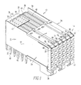
- the receptacle is shown generally at numeral 10.
- the receptacle has a first face 12 on a front insulative housing shown generally at numeral 14.
- the receptacle also has a second face 16 on its bottom side, and signal conducting means as at 18 extends from the first face to the second face.
- the first face has a plurality of openings as at 20 where, as is explained hereafter, pins from a header engage the signal conducting means.
- the receptacle also includes ground pins as at 22.
- the receptacle also includes lateral longitudinal sides 24 and 26 and a top longitudinal side 28. In opposed relation to the first face there is an end 30.
- the longitudinal 24 and 26 and the end 30 are covered by U-shaped shield 32.
- This shield is comprised of longitudinal sections 34 and 36 which are superimposed, respectively over longitudinal sides 24 and 26.
- section 38 of the U-shaped shield 32 is superimposed over the end 30 of the receptacle 10.
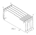
- FIGs. 1, 3 and 6 there are parallel longitudinal internal shielding walls 40, 42, 44, 46 and 48. Between these internal walls there are longitudinal spaces as at 50 (Fig. 3). Each of the internal walls also has a transverse section as at 52 and 53 (Fig. 3). Each of these transverse sections has a pair of vertical latches as at 54 and 56 on transverse section 52 and 58 and 60 on transverse section 53. These vertical latches engage horizontal eyelets as at 62 and 64 (Figs. 2 and 6). On the front top edge of the longitudinal section 34 of U-shaped shield 32 there is a spring latch 66. On the front top section of longitudinal section 36 of the U-shaped shield 32 there is also a spring latch 68.
- internal shielding wall 40 has a front spring latch 70
- internal shielding wall 42 has a shielding latch 72
- internal shielding wall 44 has a front spring latch 74
- internal shielding wall 46 has a shielding latch 76
- internal shielding wall 48 has a front spring latch 78.
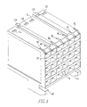
- FIG. 4 there are side slots 80 and 82 in the insulative housing. These slots are engaged, respectively, by spring latches 68 and 70. Between these slots there are medial slots 84, 86, 88, 90 and 92 which are engaged, respectively, by spring latches 70, 72, 74, 76 and 78 on the internal shielding walls.
- insulative frames 94, 96, 98, 100, 101 and 102 have, respectively, frame latches 103, 104, 106, 108, 110 and 112. These frame latches engage, respectively apertures 114, 116, 118, 120 and 122 in the insulative housing (Fig. 1).
- insulative frame 94 also holds signal terminal 124, 126, 128 and 130. Each of these terminals extends first upwardly and then horizontally. Each of these terminals has, respectively at its horizontal terminal end a split pin engagement section 132, 134, 136, 138 and 140. As is conventional, the receptacle also has a pair of code key holders 142 and 144 and press pins 146, 148 and 150.
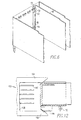
- an insulative frame is shown as being vertically bisected. This bisected frame is centrally recessed and has a plurality of contact receiving structures 151a-151h.
- the receptacle engages a header shown generally at numeral 152.
- the header has a pair of end walls 154 and 156 and a medial wall. There are apertures in the medial wall through which conductive pins as at 160 extend to engage the first face of the receptacle and be received in the split pin engagement sections of the signal conducting means.
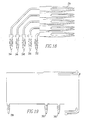
- FIG. 13 A second embodiment is shown in Figs. 13-20.
- the front face of the receptacle is shown generally at numeral 210 and a bottom face at 211. On this face there are conventional pin receiving apertures as at 212 for connection with the plug.
- the receptacle also includes, as is conventional, a press attachment peg 214 and location pegs 216 and 218. Also included are spacers 220 and 222 and polarization alignment keys 224 and 226.
- top face 228, rear face 230 and a side face 232 and 234 are shown in greater detail. From this figure it will be seen that there are slots as at 236 and 237 for receiving shields in the top face, bottom face and rear face which run parallel to the side faces. Between the shields there are elongated contact receiving slots as at 238 and 239. At vertical spaced intervals along the shield receiving slot there are also pairs of grooves 240 and 242.
- signal contacts as at 244, 246, 248, 250 and 252 pass through each of the contact receiving slots in the receptacle. These contacts are connected at one end to the printed circuit board 254 (Fig. 16). (It will be understood that the contacts between individual sets of shields all extend rearwardly by the same overall length although in Fig. 16 engagement of the printed circuit board schematically shows several different rearward positions to illustrate various positions on the board which may be engaged by the contacts.) At their other end they have a V-shaped structure as at 256 to engage pins at the pin receiving apertures. referring particularly to Figs.
- the shields have ground pins as at 258, 260 and 262 that pass through the bottom face of the receptacle to be grounded to the PCB.
- the shield also has a lower resilient ground 264 which extends downwardly through a lower slot in the receptacle then rearwardly to be grounded to a shrouded header 265 (Fig. 17B).
- the shield has an upper resilient ground structure 266 which passes through one of the slots in the upper face of the receptacle to be grounded to a header (not shown).
- a header which would be suitable for engagement with these resilient ground projections would, for example, be either one shown in U.S. Patent Application Serial No. 08/277,989 filed April 4, 1995 and assigned to the assignee of this application.
Claims (6)
- Elektrischer Steckverbinder miteinem Gehäuse (14) mit einer ersten Fläche (12) und einer zweiten Fläche (16) und mehreren Längsseiten (24, 26), mehreren Signalleitungseinrichtungen (18, 124, 126, 128, 130; 244, 246, 248 250, 252), die sich von der ersten Seite (12) durch das Gehäuse (14) zur zweiten Seite (16) erstrecken, einer äußeren leitenden Abschirmung (32), die das Gehäuse (14) umgibt und mindestens eine nach innen gerichtete Vorstehung aufweist, undmindestens einer inneren leitenden Abschirmungswand (48) in dem Gehäuse (14), die zwischen wenigstens einigen der Signalleitungseinrichtungen (18, 124,126, 128, 130; 244, 246, 248, 250, 252) angeordnet ist, dadurch gekennzeichnet, dass die Abschirmung (32) das Gehäuse (14) von drei Seiten (24, 26, 30) inklusive der zwei seitlichen Längsseiten (24, 26) umgibt, wobei mindestens eine innere leitende Abschirmungswand (40, 42, 44, 46, 48) mindestens eine Vorrichtung aufweist, die in die mindestens eine Vorstehung eingreift, wobei diese mindestens eine Vorstehung mindestens eine Öse (62, 64) und die mindestens eine Vorrichtung mindestens eine in der mindestens einen Öse (62, 64) aufnehmbare Verriegelung (56, 58) aufweist.
- Steckverbinder nach Anspruch 1, wobei die mehreren Signalleitungseinrichtungen (18, 124, 126, 128, 130; 244, 246, 248, 250, 252) in mehreren Spalten angeordnet sind, und die innere Abschirmungswand (40, 42, 44, 46, 48) zwischen benachbarten Spalten liegt.
- Elektrischer Steckverbinder nach Anspruch 1 oder 2, wobei die innere Abschirmungswand (40, 42, 44, 46, 48) mehrere im allgemeinen ebene leitende Elemente aufweist, die zwischen benachbarten Spalten verlaufen.
- Elektrischer Steckverbinder nach zumindest einen der Ansprüche 1 bis 3, wobei die äußere Abschirmung (32) eine Rückwand (38) aufweist, die sich entlang einer Rückseite des elektrischen Steckverbinders erstreckt, wobei die mindestens eine Vorstehung auf der Rückwand (38) liegt.
- Elektrischer Steckverbinder nach einem der Ansprüche 1 bis 4, wobei die äußere Abschirmung (32) weiterhin eine obere Wand (28) aufweist, die sich entlang einer Oberseite des Gehäuses (14) erstreckt.
- Elektrischer Steckverbinder nach Anspruch 3, wobei jeder der inneren Abschirmungswände (40, 42, 44, 46, 48) mindestens eine Vorrichtung aufweist, um die mindestens eine Vorstehung (62, 64) aufzunehmen.
Applications Claiming Priority (3)
| Application Number | Priority Date | Filing Date | Title |
|---|---|---|---|
| US2422096P | 1996-08-20 | 1996-08-20 | |
| US24220P | 1996-08-20 | ||
| PCT/US1997/014631 WO1998008276A1 (en) | 1996-08-20 | 1997-08-20 | High speed modular electrical connector and receptacle for use therein |
Publications (3)
| Publication Number | Publication Date |
|---|---|
| EP1016170A1 EP1016170A1 (de) | 2000-07-05 |
| EP1016170A4 EP1016170A4 (de) | 2000-10-18 |
| EP1016170B1 true EP1016170B1 (de) | 2003-02-05 |
Family
ID=21819463
Family Applications (1)
| Application Number | Title | Priority Date | Filing Date |
|---|---|---|---|
| EP97938452A Expired - Lifetime EP1016170B1 (de) | 1996-08-20 | 1997-08-20 | Hochfrequenz modularer elektrischer steckverbinder |
Country Status (6)
| Country | Link |
|---|---|
| US (1) | US6354877B1 (de) |
| EP (1) | EP1016170B1 (de) |
| JP (1) | JP2000516385A (de) |
| KR (1) | KR100458244B1 (de) |
| DE (1) | DE69718948T2 (de) |
| WO (1) | WO1998008276A1 (de) |
Families Citing this family (55)
| Publication number | Priority date | Publication date | Assignee | Title |
|---|---|---|---|---|
| DE19853837C1 (de) | 1998-11-23 | 2000-02-24 | Krone Ag | Abschirmeinrichtung für Anschlußleisten der Telekommunikations- und Datentechnik |
| US6565387B2 (en) * | 1999-06-30 | 2003-05-20 | Teradyne, Inc. | Modular electrical connector and connector system |
| KR100808728B1 (ko) * | 2000-06-29 | 2008-02-29 | 쓰리엠 이노베이티브 프로퍼티즈 캄파니 | 고속 커넥터 |
| US6585540B2 (en) * | 2000-12-06 | 2003-07-01 | Pulse Engineering | Shielded microelectronic connector assembly and method of manufacturing |
| US6663401B2 (en) * | 2000-12-21 | 2003-12-16 | Hon Hai Precision Ind. Co., Ltd. | Electrical connector |
| US6869292B2 (en) * | 2001-07-31 | 2005-03-22 | Fci Americas Technology, Inc. | Modular mezzanine connector |
| US6981883B2 (en) * | 2001-11-14 | 2006-01-03 | Fci Americas Technology, Inc. | Impedance control in electrical connectors |
| US7390200B2 (en) * | 2001-11-14 | 2008-06-24 | Fci Americas Technology, Inc. | High speed differential transmission structures without grounds |
| US20050196987A1 (en) * | 2001-11-14 | 2005-09-08 | Shuey Joseph B. | High density, low noise, high speed mezzanine connector |
| US6994569B2 (en) * | 2001-11-14 | 2006-02-07 | Fci America Technology, Inc. | Electrical connectors having contacts that may be selectively designated as either signal or ground contacts |
| US20050170700A1 (en) * | 2001-11-14 | 2005-08-04 | Shuey Joseph B. | High speed electrical connector without ground contacts |
| EP2451024A3 (de) * | 2001-11-14 | 2013-03-06 | Fci | Gegenseitige Störbeeinflussung für elektrische Anschlüsse |
| US6520803B1 (en) * | 2002-01-22 | 2003-02-18 | Fci Americas Technology, Inc. | Connection of shields in an electrical connector |
| US6638079B1 (en) * | 2002-05-21 | 2003-10-28 | Hon Hai Precision Ind. Co., Ltd. | Customizable electrical connector |
| US6905367B2 (en) * | 2002-07-16 | 2005-06-14 | Silicon Bandwidth, Inc. | Modular coaxial electrical interconnect system having a modular frame and electrically shielded signal paths and a method of making the same |
| US6884117B2 (en) * | 2003-08-29 | 2005-04-26 | Hon Hai Precision Ind. Co., Ltd. | Electrical connector having circuit board modules positioned between metal stiffener and a housing |
| US7524209B2 (en) * | 2003-09-26 | 2009-04-28 | Fci Americas Technology, Inc. | Impedance mating interface for electrical connectors |
| WO2005031922A2 (en) | 2003-09-26 | 2005-04-07 | Fci Americas Technology, Inc. | Improved impedance mating interface for electrical connectors |
| US7281950B2 (en) * | 2004-09-29 | 2007-10-16 | Fci Americas Technology, Inc. | High speed connectors that minimize signal skew and crosstalk |
| US20060228912A1 (en) * | 2005-04-07 | 2006-10-12 | Fci Americas Technology, Inc. | Orthogonal backplane connector |
| US20060245137A1 (en) * | 2005-04-29 | 2006-11-02 | Fci Americas Technology, Inc. | Backplane connectors |
| US7195519B1 (en) * | 2006-03-30 | 2007-03-27 | Tyco Electronics Corporation | Modular connector assembly with adjustable distance between contact wafers |
| US7175479B1 (en) * | 2006-04-25 | 2007-02-13 | Tyco Electronics Corporation | Modular connector assembly with stamped retention latch members |
| US7462924B2 (en) * | 2006-06-27 | 2008-12-09 | Fci Americas Technology, Inc. | Electrical connector with elongated ground contacts |
| CN2932730Y (zh) * | 2006-07-14 | 2007-08-08 | 富士康(昆山)电脑接插件有限公司 | 具有屏蔽壳体的电连接器 |
| US7500871B2 (en) * | 2006-08-21 | 2009-03-10 | Fci Americas Technology, Inc. | Electrical connector system with jogged contact tails |
| US7713088B2 (en) | 2006-10-05 | 2010-05-11 | Fci | Broadside-coupled signal pair configurations for electrical connectors |
| US7708569B2 (en) | 2006-10-30 | 2010-05-04 | Fci Americas Technology, Inc. | Broadside-coupled signal pair configurations for electrical connectors |
| US7497736B2 (en) * | 2006-12-19 | 2009-03-03 | Fci Americas Technology, Inc. | Shieldless, high-speed, low-cross-talk electrical connector |
| US7811100B2 (en) * | 2007-07-13 | 2010-10-12 | Fci Americas Technology, Inc. | Electrical connector system having a continuous ground at the mating interface thereof |
| JP4980183B2 (ja) * | 2007-09-12 | 2012-07-18 | 富士通コンポーネント株式会社 | ソケットコネクタ |
| CN101471515B (zh) | 2007-12-29 | 2011-06-15 | 富士康(昆山)电脑接插件有限公司 | 电连接器 |
| US8764464B2 (en) * | 2008-02-29 | 2014-07-01 | Fci Americas Technology Llc | Cross talk reduction for high speed electrical connectors |
| CN102282731B (zh) | 2008-11-14 | 2015-10-21 | 莫列斯公司 | 共振修正连接器 |
| WO2010068671A1 (en) | 2008-12-12 | 2010-06-17 | Molex Incorporated | Resonance modifying connector |
| US9277649B2 (en) | 2009-02-26 | 2016-03-01 | Fci Americas Technology Llc | Cross talk reduction for high-speed electrical connectors |
| US8366485B2 (en) | 2009-03-19 | 2013-02-05 | Fci Americas Technology Llc | Electrical connector having ribbed ground plate |
| US8608510B2 (en) * | 2009-07-24 | 2013-12-17 | Fci Americas Technology Llc | Dual impedance electrical connector |
| US8267721B2 (en) * | 2009-10-28 | 2012-09-18 | Fci Americas Technology Llc | Electrical connector having ground plates and ground coupling bar |
| US8616919B2 (en) * | 2009-11-13 | 2013-12-31 | Fci Americas Technology Llc | Attachment system for electrical connector |
| EP2519994A4 (de) * | 2009-12-30 | 2015-01-21 | Fci Asia Pte Ltd | Elektrischer steckverbinder mit impedanzabstimmungsrippen |
| US9136634B2 (en) | 2010-09-03 | 2015-09-15 | Fci Americas Technology Llc | Low-cross-talk electrical connector |
| EP2624034A1 (de) | 2012-01-31 | 2013-08-07 | Fci | Abbaubare optische Kupplungsvorrichtung |
| USD718253S1 (en) | 2012-04-13 | 2014-11-25 | Fci Americas Technology Llc | Electrical cable connector |
| USD727852S1 (en) | 2012-04-13 | 2015-04-28 | Fci Americas Technology Llc | Ground shield for a right angle electrical connector |
| USD727268S1 (en) | 2012-04-13 | 2015-04-21 | Fci Americas Technology Llc | Vertical electrical connector |
| US9257778B2 (en) | 2012-04-13 | 2016-02-09 | Fci Americas Technology | High speed electrical connector |
| US8944831B2 (en) | 2012-04-13 | 2015-02-03 | Fci Americas Technology Llc | Electrical connector having ribbed ground plate with engagement members |
| USD751507S1 (en) | 2012-07-11 | 2016-03-15 | Fci Americas Technology Llc | Electrical connector |
| US9543703B2 (en) | 2012-07-11 | 2017-01-10 | Fci Americas Technology Llc | Electrical connector with reduced stack height |
| USD745852S1 (en) | 2013-01-25 | 2015-12-22 | Fci Americas Technology Llc | Electrical connector |
| USD720698S1 (en) | 2013-03-15 | 2015-01-06 | Fci Americas Technology Llc | Electrical cable connector |
| CN104167631B (zh) * | 2013-05-16 | 2017-07-25 | 富士康(昆山)电脑接插件有限公司 | 电连接器 |
| CN106415944A (zh) | 2014-04-23 | 2017-02-15 | 泰科电子公司 | 具有屏蔽帽和屏蔽端子的电连接器 |
| EP3447852A4 (de) * | 2016-07-29 | 2019-05-01 | Avic Jonhon Optronic Technology Co., Ltd. | Differenzialstecker und gehäuseteil davon |
Family Cites Families (9)
| Publication number | Priority date | Publication date | Assignee | Title |
|---|---|---|---|---|
| US4846727A (en) * | 1988-04-11 | 1989-07-11 | Amp Incorporated | Reference conductor for improving signal integrity in electrical connectors |
| US4973260A (en) | 1989-08-29 | 1990-11-27 | Thomas & Betts Corporation | Connector for interconnection of printed circuit boards |
| DE69018000T2 (de) * | 1989-10-10 | 1995-09-28 | Whitaker Corp | Rückwandsteckverbinder mit angepasster Impedanz. |
| GB8928777D0 (en) | 1989-12-20 | 1990-02-28 | Amp Holland | Sheilded backplane connector |
| GB9205088D0 (en) | 1992-03-09 | 1992-04-22 | Amp Holland | Shielded back plane connector |
| NL9300971A (nl) * | 1993-06-04 | 1995-01-02 | Framatome Connectors Belgium | Connectorsamenstel voor printkaarten. |
| DE59401765D1 (de) | 1994-03-03 | 1997-03-20 | Siemens Ag | Steckverbinder für Rückwandverdrahtungen |
| US5672064A (en) | 1995-12-21 | 1997-09-30 | Teradyne, Inc. | Stiffener for electrical connector |
| US5718606A (en) | 1996-10-30 | 1998-02-17 | Component Equipment Company, Inc. | Electrical connector between a pair of printed circuit boards |
-
1997
- 1997-08-20 WO PCT/US1997/014631 patent/WO1998008276A1/en active IP Right Grant
- 1997-08-20 EP EP97938452A patent/EP1016170B1/de not_active Expired - Lifetime
- 1997-08-20 DE DE69718948T patent/DE69718948T2/de not_active Expired - Lifetime
- 1997-08-20 JP JP10510916A patent/JP2000516385A/ja active Pending
-
1999
- 1999-02-19 KR KR10-1999-7001375A patent/KR100458244B1/ko not_active IP Right Cessation
-
2000
- 2000-07-25 US US09/625,106 patent/US6354877B1/en not_active Expired - Lifetime
Also Published As
| Publication number | Publication date |
|---|---|
| EP1016170A1 (de) | 2000-07-05 |
| DE69718948T2 (de) | 2003-12-24 |
| WO1998008276A1 (en) | 1998-02-26 |
| KR100458244B1 (ko) | 2004-11-26 |
| DE69718948D1 (de) | 2003-03-13 |
| US6354877B1 (en) | 2002-03-12 |
| EP1016170A4 (de) | 2000-10-18 |
| JP2000516385A (ja) | 2000-12-05 |
Similar Documents
| Publication | Publication Date | Title |
|---|---|---|
| EP1016170B1 (de) | Hochfrequenz modularer elektrischer steckverbinder | |
| US6361366B1 (en) | High speed modular electrical connector and receptacle for use therein | |
| CN108365362B (zh) | 用于触头模块的接地屏蔽件 | |
| US5967844A (en) | Electrically enhanced modular connector for printed wiring board | |
| US7785148B2 (en) | High speed electrical connector having improved shield | |
| CN107863655B (zh) | 在与电路板的接口处具有屏蔽的电连接器 | |
| US5104341A (en) | Shielded backplane connector | |
| JP2589178B2 (ja) | 多数の信号コンタクトを有する電気コネクタ | |
| US7553190B2 (en) | High-density, robust connector with dielectric insert | |
| EP1485973B1 (de) | Verbindungskopfteil und abschirmung | |
| CN108365465B (zh) | 具有配合连接器接口的电连接器 | |
| US7905751B1 (en) | Electrical connector module with contacts of a differential pair held in separate chicklets | |
| WO2005022698A8 (en) | Stacked sfp connector and cage assembly | |
| JP2003022877A (ja) | 直角コネクタ | |
| JPH07169532A (ja) | プリント回路基板用コネクタ装置 | |
| WO2003030304A2 (en) | High speed docking connector | |
| BG62749B1 (bg) | Съединителна рейка за високи скорости на предаване | |
| US6579124B1 (en) | Shielded electrical connector | |
| US20040248464A1 (en) | Stacked electrical connector assembly | |
| CA2242287C (en) | Connector | |
| EP0995239B1 (de) | Vorrichtung zur herstellung einer verbindung durch eine platte |
Legal Events
| Date | Code | Title | Description |
|---|---|---|---|
| PUAI | Public reference made under article 153(3) epc to a published international application that has entered the european phase |
Free format text: ORIGINAL CODE: 0009012 |
|
| 17P | Request for examination filed |
Effective date: 19990310 |
|
| AK | Designated contracting states |
Kind code of ref document: A1 Designated state(s): DE FR GB |
|
| A4 | Supplementary search report drawn up and despatched |
Effective date: 20000901 |
|
| AK | Designated contracting states |
Kind code of ref document: A4 Designated state(s): DE FR GB |
|
| RIC1 | Information provided on ipc code assigned before grant |
Free format text: 7H 01R 13/658 A, 7H 01R 23/68 B |
|
| 17Q | First examination report despatched |
Effective date: 20010209 |
|
| RIC1 | Information provided on ipc code assigned before grant |
Free format text: 7H 01R 13/658 A, 7H 01R 12/16 B |
|
| RTI1 | Title (correction) |
Free format text: HIGH SPEED MODULAR ELECTRICAL CONNECTOR |
|
| RIC1 | Information provided on ipc code assigned before grant |
Free format text: 7H 01R 13/658 A, 7H 01R 12/16 B |
|
| RTI1 | Title (correction) |
Free format text: HIGH SPEED MODULAR ELECTRICAL CONNECTOR |
|
| GRAG | Despatch of communication of intention to grant |
Free format text: ORIGINAL CODE: EPIDOS AGRA |
|
| GRAG | Despatch of communication of intention to grant |
Free format text: ORIGINAL CODE: EPIDOS AGRA |
|
| GRAH | Despatch of communication of intention to grant a patent |
Free format text: ORIGINAL CODE: EPIDOS IGRA |
|
| RAP1 | Party data changed (applicant data changed or rights of an application transferred) |
Owner name: FCI |
|
| GRAH | Despatch of communication of intention to grant a patent |
Free format text: ORIGINAL CODE: EPIDOS IGRA |
|
| GRAA | (expected) grant |
Free format text: ORIGINAL CODE: 0009210 |
|
| AK | Designated contracting states |
Designated state(s): DE FR GB |
|
| REG | Reference to a national code |
Ref country code: GB Ref legal event code: FG4D |
|
| REF | Corresponds to: |
Ref document number: 69718948 Country of ref document: DE Date of ref document: 20030313 Kind code of ref document: P |
|
| ET | Fr: translation filed | ||
| PLBE | No opposition filed within time limit |
Free format text: ORIGINAL CODE: 0009261 |
|
| STAA | Information on the status of an ep patent application or granted ep patent |
Free format text: STATUS: NO OPPOSITION FILED WITHIN TIME LIMIT |
|
| 26N | No opposition filed |
Effective date: 20031106 |
|
| REG | Reference to a national code |
Ref country code: FR Ref legal event code: CA |
|
| REG | Reference to a national code |
Ref country code: DE Ref legal event code: R082 Ref document number: 69718948 Country of ref document: DE Representative=s name: BEETZ & PARTNER MBB PATENT- UND RECHTSANWAELTE, DE Effective date: 20120419 Ref country code: DE Ref legal event code: R082 Ref document number: 69718948 Country of ref document: DE Representative=s name: BEETZ & PARTNER MBB, DE Effective date: 20120419 Ref country code: DE Ref legal event code: R082 Ref document number: 69718948 Country of ref document: DE Representative=s name: BEETZ & PARTNER PATENT- UND RECHTSANWAELTE, DE Effective date: 20120419 Ref country code: DE Ref legal event code: R081 Ref document number: 69718948 Country of ref document: DE Owner name: FCI, FR Free format text: FORMER OWNER: FCI, PARIS, FR Effective date: 20120419 |
|
| REG | Reference to a national code |
Ref country code: FR Ref legal event code: PLFP Year of fee payment: 20 |
|
| PGFP | Annual fee paid to national office [announced via postgrant information from national office to epo] |
Ref country code: DE Payment date: 20160831 Year of fee payment: 20 Ref country code: GB Payment date: 20160725 Year of fee payment: 20 |
|
| PGFP | Annual fee paid to national office [announced via postgrant information from national office to epo] |
Ref country code: FR Payment date: 20160719 Year of fee payment: 20 |
|
| REG | Reference to a national code |
Ref country code: DE Ref legal event code: R071 Ref document number: 69718948 Country of ref document: DE |
|
| REG | Reference to a national code |
Ref country code: GB Ref legal event code: PE20 Expiry date: 20170819 |
|
| PG25 | Lapsed in a contracting state [announced via postgrant information from national office to epo] |
Ref country code: GB Free format text: LAPSE BECAUSE OF EXPIRATION OF PROTECTION Effective date: 20170819 |