EP1014892B1 - Dispositif de rattrapage d'un tendon rompu - Google Patents
Dispositif de rattrapage d'un tendon rompu Download PDFInfo
- Publication number
- EP1014892B1 EP1014892B1 EP98900642A EP98900642A EP1014892B1 EP 1014892 B1 EP1014892 B1 EP 1014892B1 EP 98900642 A EP98900642 A EP 98900642A EP 98900642 A EP98900642 A EP 98900642A EP 1014892 B1 EP1014892 B1 EP 1014892B1
- Authority
- EP
- European Patent Office
- Prior art keywords
- arms
- tendon
- instrument
- pair
- internal
- Prior art date
- Legal status (The legal status is an assumption and is not a legal conclusion. Google has not performed a legal analysis and makes no representation as to the accuracy of the status listed.)
- Expired - Lifetime
Links
- 206010043248 Tendon rupture Diseases 0.000 title description 2
- 210000002435 tendon Anatomy 0.000 claims abstract description 45
- 230000007246 mechanism Effects 0.000 claims description 8
- 238000003780 insertion Methods 0.000 claims description 3
- 230000037431 insertion Effects 0.000 claims description 3
- 229920003023 plastic Polymers 0.000 claims description 3
- 239000004033 plastic Substances 0.000 claims description 3
- 229910001220 stainless steel Inorganic materials 0.000 claims description 3
- 239000010935 stainless steel Substances 0.000 claims description 3
- 238000000926 separation method Methods 0.000 claims 2
- 238000005553 drilling Methods 0.000 claims 1
- 239000000463 material Substances 0.000 claims 1
- 238000000034 method Methods 0.000 description 10
- 210000000459 calcaneus Anatomy 0.000 description 5
- 230000008439 repair process Effects 0.000 description 5
- 230000000717 retained effect Effects 0.000 description 4
- 210000003205 muscle Anatomy 0.000 description 3
- 238000002559 palpation Methods 0.000 description 3
- 206010002091 Anaesthesia Diseases 0.000 description 2
- 230000037005 anaesthesia Effects 0.000 description 2
- 230000008602 contraction Effects 0.000 description 2
- 210000002683 foot Anatomy 0.000 description 2
- 210000000474 heel Anatomy 0.000 description 2
- 208000014674 injury Diseases 0.000 description 2
- 238000009434 installation Methods 0.000 description 2
- 238000001356 surgical procedure Methods 0.000 description 2
- 210000001519 tissue Anatomy 0.000 description 2
- 208000027418 Wounds and injury Diseases 0.000 description 1
- 210000001361 achilles tendon Anatomy 0.000 description 1
- 230000001174 ascending effect Effects 0.000 description 1
- 210000000988 bone and bone Anatomy 0.000 description 1
- 230000000295 complement effect Effects 0.000 description 1
- 230000006378 damage Effects 0.000 description 1
- 230000007850 degeneration Effects 0.000 description 1
- 230000001627 detrimental effect Effects 0.000 description 1
- 210000003414 extremity Anatomy 0.000 description 1
- 239000007943 implant Substances 0.000 description 1
- 230000035515 penetration Effects 0.000 description 1
- 230000008569 process Effects 0.000 description 1
- 230000002035 prolonged effect Effects 0.000 description 1
- 238000011084 recovery Methods 0.000 description 1
- 230000009467 reduction Effects 0.000 description 1
- 231100000241 scar Toxicity 0.000 description 1
- 238000010008 shearing Methods 0.000 description 1
- 210000004872 soft tissue Anatomy 0.000 description 1
- 238000007920 subcutaneous administration Methods 0.000 description 1
- 238000011477 surgical intervention Methods 0.000 description 1
- 230000008733 trauma Effects 0.000 description 1
- 230000000472 traumatic effect Effects 0.000 description 1
Images

Classifications
-
- A—HUMAN NECESSITIES
- A61—MEDICAL OR VETERINARY SCIENCE; HYGIENE
- A61B—DIAGNOSIS; SURGERY; IDENTIFICATION
- A61B17/00—Surgical instruments, devices or methods
- A61B17/04—Surgical instruments, devices or methods for suturing wounds; Holders or packages for needles or suture materials
- A61B17/0469—Suturing instruments for use in minimally invasive surgery, e.g. endoscopic surgery
-
- A—HUMAN NECESSITIES
- A61—MEDICAL OR VETERINARY SCIENCE; HYGIENE
- A61B—DIAGNOSIS; SURGERY; IDENTIFICATION
- A61B17/00—Surgical instruments, devices or methods
- A61B17/04—Surgical instruments, devices or methods for suturing wounds; Holders or packages for needles or suture materials
- A61B17/0482—Needle or suture guides
-
- A—HUMAN NECESSITIES
- A61—MEDICAL OR VETERINARY SCIENCE; HYGIENE
- A61B—DIAGNOSIS; SURGERY; IDENTIFICATION
- A61B17/00—Surgical instruments, devices or methods
- A61B17/04—Surgical instruments, devices or methods for suturing wounds; Holders or packages for needles or suture materials
- A61B17/06—Needles ; Sutures; Needle-suture combinations; Holders or packages for needles or suture materials
- A61B17/062—Needle manipulators
- A61B17/0625—Needle manipulators the needle being specially adapted to interact with the manipulator, e.g. being ridged to snap fit in a hole of the manipulator
-
- A—HUMAN NECESSITIES
- A61—MEDICAL OR VETERINARY SCIENCE; HYGIENE
- A61B—DIAGNOSIS; SURGERY; IDENTIFICATION
- A61B17/00—Surgical instruments, devices or methods
- A61B17/11—Surgical instruments, devices or methods for performing anastomosis; Buttons for anastomosis
- A61B17/1146—Surgical instruments, devices or methods for performing anastomosis; Buttons for anastomosis of tendons
-
- A—HUMAN NECESSITIES
- A61—MEDICAL OR VETERINARY SCIENCE; HYGIENE
- A61B—DIAGNOSIS; SURGERY; IDENTIFICATION
- A61B90/00—Instruments, implements or accessories specially adapted for surgery or diagnosis and not covered by any of the groups A61B1/00 - A61B50/00, e.g. for luxation treatment or for protecting wound edges
- A61B90/06—Measuring instruments not otherwise provided for
- A61B2090/062—Measuring instruments not otherwise provided for penetration depth
Definitions
- the present invention relates to a device used, during a surgical operation to repair a ruptured Achilles tendon, to catch up the tendon end secured to the triceps muscle and located within its sheath peritendinous. This device can also be used to catch up with other tendons of the human body.
- Achilles tendon may rupture due to trauma accidental or due to degeneration due to age. Usually the tendon breaks transversely about 4 cm above its insertion on the calcaneus, and goes up by the contraction of the triceps more or less high to the inside of its peritendinous sheath.
- the surgical repair operation consists in catching the extremity upper part of the tendon to pull it down until it is brought back end-to-end with the lower end secured to the calcaneus, and to suture them together. This operation must therefore restore the original length of the tendon, minimize the adhesion between the tendon and the surrounding tissues and leave a minimum of scar.
- An invasive technique consists of making a long incision, of the order of 15 cm, in the skin area posterior leg along the triceps muscle and then from the tendon to calcaneus to go find the two ends of the tendons and put them back together.
- this technique is disadvantageous because of the length significant incision of skin tissue and peritendon, source of vascularity of the tendon itself.
- this area has critical vascularity and is highly stressed by friction with the back of the shoes.
- the object of the present invention is a device comprising a instrument and an adapted needle notably facilitating the surgical operation of repair of a tendon, especially Achilles by the minimally invasive subcutaneous process previously described.
- this device must avoid any risk of additional injury, be relatively simple in design to be easy to to implement and inexpensive to carry out. This device must therefore allow significantly reduce the average time required for such an operation, while allowing a perfect suture of the tendon thereafter.
- a device comprising an instrument composed of a pair of internal branches intended to be inserted in the sheath on either side of the tendon and an external manipulation handle including one element is located in the plane of the pair of branches and opposite, the element and the pair of internal branches respectively having at least one orifice along a same alignment passing through the tendon; and a needle that can be inserted in the element orifice to be guided in order to pass through the orifices of internal branches.
- the orifice of the handle element allows guide the needle in a precise direction allowing it to pass inevitably and without visibility through the tendon which is moreover retained by these branches during its piercing.
- the operation of threading a wire into this tendon becomes particularly fast, which shortens the duration of surgical intervention.
- the handle element and the pair of internal branches respectively have the same network of aligned orifices, if desired, the mouths of branch openings being chamfered.
- this characteristic advantageously increases the chances of success of rapid passage of the needle through the tendon, however even the pair of arms is not exactly aligned with this tendon.
- this network of orifices allows several wires to be passed before removing the instrument.
- the chamfered mouthpieces allow easy catching of slight deviations of the needle out of alignment with the holes.
- the two internal branches form an angle between them corner angle between 2 ° and 8 °, preferably 4 °, open in the direction introduction. This characteristic allows the pair of branches to come and marry the conical outline of the tendon end without risking pushing it further back in its sheath.
- the internal branches of the instrument have a flattened rectangular cross section with rounded corners, or an oval section flattened, if desired the greatest length of this section tapering towards the end. These internal branches then slide better between the tendon and its peritendinous sheath during installation of the instrument.
- the spacing between the two internal branches is adjustable.
- the instrument can then be adapted to the different morphologies of the patients.
- the element of the handle comprises two branches external respectively located on either side of the pair of internal branches in the same plane.
- the instrument can then be comfortably used as well by a right-handed surgeon than a left-handed one when he grasps the instrument by one of the external branches.
- the instrument is preferably made up of two parts substantially U-shaped and assembled side by side by a mechanism allowing adjust the spacing between the parts, the adjacent U branches of each of the parts forming the pair of internal branches, the distant branches forming the handle.
- the design of this instrument is particularly simple and easy to achieve.
- the two U-shaped parts are symmetrical about a plane orthogonal, and the junction base of the branches of the U-shaped parts is arched.
- the even more simplified appearance of the instrument facilitates its handling on one side like the other.
- the arcuate joining of the pieces facilitates the introduction of the branches internals in the sheath without the instrument rubbing against the heel of the foot.
- the assembly and adjustment mechanism of the two parts side-by-side comprises at least one rod integral with one of the parts and sliding in a corresponding hole in the other room as well as a screw rotatably mounted in one of the parts with its thread engaged in a tapped hole in the other room, the head of the screw being visible at outside for handling.
- This adjustment mechanism is also simple to realize and obvious to implement.
- the eye of the needle has a reduced thickness.
- the reduction of the thickness of the eye takes into account the thickness of the wire, the eye and the wire can pass through the holes without risk of shearing or cutting.
- the instrument and the needle are made of stainless steel, or the disposable instrument is made of plastic.
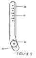
- Figure 1 a device for catching a tendon Achilles comprising on the one hand an instrument 20 intended to be inserted in part at inside the peritendinous sheath and on the other hand a needle 10 provided for pass a wire through the raised upper tendon.
- the instrument 20 is in the form of two U-shaped parts 30, 31 assembled by two retaining pins 42 and retained with a spacing desired by an adjustment screw 40.
- the two U-shaped parts 30, 31 are rigorously symmetrical with respect to one median plane orthogonal to the needle 10.
- Each U-shaped part therefore has two branches 33/34, 36/37 joined together by a junction base 32/39.
- the two external branches 33, 37 are substantially straight and fairly thick, i.e. they have a height of about 70mm for a constant section of about 7mm wide for 12mm long.
- the two internal branches 34, 36 substantially of same height, have a thinner section going in particular to shrinking up.
- the branches 34, 36 have downwards a substantially rectangular section with a width of 5mm over a length of 12mm, this width being reduced to around 2mm upwards.
- the internal branches 34, 36 are not parallel to each other, like the external branches 33, 37, but form an open upward angle between them angle at the top between 2o and 8o, preferably 4o.
- the length of branches 34/36 corresponds to the maximum ascending height observed from tendon by the contraction of the muscle.
- Junctions 32/39 have sufficient volume to contain a mechanism for connecting and adjusting the two U-shaped parts 30, 31, one with respect to the other. More particularly, this mechanism firstly comprises a pair of axes of holding 42 integral with one of the parts, for example part 30, and sliding in corresponding blind holes made in junction 39 of the other parts 31. These two axes 42 therefore maintain the parts 30 and 31 in a same plan.
- This mechanism further comprises a movable mounted adjustment screw 40 in rotation but retained axially in one of the junctions, for example that 32 of part 30, the threaded rod of this screw 40 being engaged in a threaded orifice 45 arranged in correspondence in the other junction 39.
- this adjusting screw is preferably installed halfway between the two axes 42.
- all the edges of the pieces 30; 31 are rounded to avoid grabbing, or even cutting, soft tissue. More in particular, the upper ends of the internal branches 34/36 are rounded according to two successive circular curves, a first internal curve with a radius of around 5mm, and an outer end curve with a radius of around 1.7mm.
- all the branches of the two parts have a same network of orifices 35, 38, four orifices respectively of each branch being always located on the same alignment so as to receive the needle 10 as illustrated in FIG. 1.
- These orifices have an internal diameter included between 0.8mm and 2mm, preferably 1.6mm, These holes have chamfers inlet and outlet diameters of the order of 2.5mm.
- the orifices 35 of these branches act as guide holes for a needle 10 making it necessarily conducted in such a way that it can be inserted into the holes of passage 38 of the internal branches 34, 36.
- the chamfers formed in the mouths of these orifices assist in this insertion.
- a first handle 22 can be arranged under the junction 32 of the part 30 in its extension inferior.
- the 20 according to the invention can be made of polished stainless steel which can be sterilized after each operation.
- the instrument 20 can also be made of sterile plastic, this instrument only being intended for single use.
- the device comprises a needle 10 with a diameter between 0.7mm and 1.9mm, preferably 1.5mm, which is then sufficiently rigid without being traumatic.
- the length of the needle is preferably greater than the width of the instrument, therefore of the order of 80 mm, although longer or shorter needles are also usable.
- the eye 12 of this needle is formed within a restriction 14 of lesser thickness so that with the wire performing at this level a loop, the total diameter remains less than that of 1.6mm of the orifices 35, 38 by which are planned to pass.
- the operative technique of tendon repair Achilles is significantly facilitated as will now be explained below.
- the surgeon After installation of the patient and then anesthesia, the surgeon performs a small incision, advantageously vertical, of reduced length of the order of 2-3cm.
- the surgeon can then introduce the internal branches 34 and 36 through this incision in the peritendinous sheath and bring these branches up inside the sheath until it reaches the distal end of the tendon.
- Branches 34, 36 presenting an open angle, they naturally come to position on the side and on the other side of this tendon by marrying its conical shape. The presence of the tendon between the branches 34, 36 can be easily seen by palpation.
- the needle 10 into one of the guide holes 35 so that, after penetration through the skin, it passes necessarily by the corresponding orifice of the adjacent internal branch, for example 36, then leading it directly into the tendon which, when pierced, is retained by the other opposite internal branch 34.
- the advancement of the needle 10 continues entering the branch passage orifice 34 to come out of the skin in passing through the guide hole 35 of the opposite external branch 33.
- Two other complementary threads can then be threaded quickly in the same way.
- the instrument 20 is slowly pulled back causing the internal branches 34, 36 to withdraw from the sheath, taking with they the wires crossing the tendon. These six ends of wires then come out of the small incision made at the start.
- this simple device greatly facilitates a delicate operation to perform.
- junctions 32, 39 may have a curvature making it possible to introduce the branches 34, 36 all along the peritendinous sheath without risking rubbing, or even hit the heel of the foot.
- one of the holding axes 42 can be deleted so as not to keep only one, larger, working in association with the adjusting screw.
- This retaining pin may also not have a circular section, but a polygonal section, in particular circular or rectangular preventing a rotation of the U-pieces relative to each other.
- a screw locking device once the spacing has been adjusted, for example a lock nut arranged between the two parts 30, 31.
Landscapes
- Health & Medical Sciences (AREA)
- Life Sciences & Earth Sciences (AREA)
- Surgery (AREA)
- Veterinary Medicine (AREA)
- Engineering & Computer Science (AREA)
- Biomedical Technology (AREA)
- Heart & Thoracic Surgery (AREA)
- Medical Informatics (AREA)
- Molecular Biology (AREA)
- Animal Behavior & Ethology (AREA)
- General Health & Medical Sciences (AREA)
- Public Health (AREA)
- Nuclear Medicine, Radiotherapy & Molecular Imaging (AREA)
- Rheumatology (AREA)
- Orthopedic Medicine & Surgery (AREA)
- Surgical Instruments (AREA)
- Prostheses (AREA)
- Electrical Discharge Machining, Electrochemical Machining, And Combined Machining (AREA)
- Making Paper Articles (AREA)
- Mechanical Treatment Of Semiconductor (AREA)
- Medicines Containing Material From Animals Or Micro-Organisms (AREA)
- Control And Other Processes For Unpacking Of Materials (AREA)
- Load-Engaging Elements For Cranes (AREA)
- Electric Cable Installation (AREA)
- Steering Devices For Bicycles And Motorcycles (AREA)
- Portable Nailing Machines And Staplers (AREA)
- Walking Sticks, Umbrellas, And Fans (AREA)
Applications Claiming Priority (3)
| Application Number | Priority Date | Filing Date | Title |
|---|---|---|---|
| CH00246/97A CH691285A5 (fr) | 1997-02-05 | 1997-02-05 | Dispositif de rattrapage d'un tendon rompu. |
| CH24697 | 1997-02-05 | ||
| PCT/IB1998/000121 WO1998034566A1 (fr) | 1997-02-05 | 1998-01-30 | Dispositif de rattrapage d'un tendon rompu |
Publications (2)
| Publication Number | Publication Date |
|---|---|
| EP1014892A1 EP1014892A1 (fr) | 2000-07-05 |
| EP1014892B1 true EP1014892B1 (fr) | 2003-07-30 |
Family
ID=4182636
Family Applications (1)
| Application Number | Title | Priority Date | Filing Date |
|---|---|---|---|
| EP98900642A Expired - Lifetime EP1014892B1 (fr) | 1997-02-05 | 1998-01-30 | Dispositif de rattrapage d'un tendon rompu |
Country Status (11)
| Country | Link |
|---|---|
| US (1) | US6200327B1 (enExample) |
| EP (1) | EP1014892B1 (enExample) |
| JP (1) | JP3992748B2 (enExample) |
| AT (1) | ATE245953T1 (enExample) |
| AU (1) | AU730550B2 (enExample) |
| CH (1) | CH691285A5 (enExample) |
| DE (1) | DE69816840T2 (enExample) |
| DK (1) | DK1014892T3 (enExample) |
| ES (1) | ES2205435T3 (enExample) |
| PT (1) | PT1014892E (enExample) |
| WO (1) | WO1998034566A1 (enExample) |
Families Citing this family (17)
| Publication number | Priority date | Publication date | Assignee | Title |
|---|---|---|---|---|
| DE10015944C2 (de) * | 2000-03-29 | 2002-02-28 | Univ Dresden Tech | Nahtinstrument für die peritendineumerhaltende, percutane Achillessehnennaht |
| US7615062B2 (en) * | 2004-10-25 | 2009-11-10 | Deland Jonathan T | Suture guide and ruptured tissue repair |
| EP1830715B1 (en) | 2004-10-25 | 2016-12-07 | Jonathan T. Deland | Suture guide |
| EP2180836A4 (en) * | 2007-07-26 | 2015-08-12 | Alpha Scient Corp | SUTURE SURGICAL DEVICE, METHOD AND TOOLS USED THEREWITH |
| US9226748B2 (en) * | 2007-07-26 | 2016-01-05 | Alpha Scientific Corporation | Surgical suturing device, method and tools used therewith |
| US9636110B2 (en) | 2013-03-13 | 2017-05-02 | Alpha Scientific Corporation | Structural support incorporating multiple strands |
| JP6346659B2 (ja) | 2013-03-15 | 2018-06-20 | アルファ サイエンティフィック コーポレイションAlpha Scientific Corporation | 横係合を備える外科用縫合装置 |
| CN103417252B (zh) * | 2013-08-13 | 2015-05-27 | 中国人民解放军总医院 | 一种跟腱缝合器 |
| JP6332889B2 (ja) * | 2015-01-30 | 2018-05-30 | 華 陳 | アキレス腱用縫合器 |
| RU2590870C1 (ru) * | 2015-04-27 | 2016-07-10 | Государственное бюджетное образовательное учреждение высшего профессионального образования "Самарский государственный медицинский университет" Министерства здравоохранения Российской Федерации | Способ оперативного лечения подкожного дистального разрыва ахиллова сухожилия |
| WO2022010820A1 (en) * | 2020-07-07 | 2022-01-13 | The General Hospital Corporation | Devices and method for facilitating placement of sutures in a surgical procedure |
| EP4188279B1 (en) | 2020-07-27 | 2025-08-27 | Jonathan T. Deland | Achilles tendon repair device |
| SE545095C2 (en) * | 2020-12-18 | 2023-03-28 | Invivopower Ab | Surgical needle guiding arrangement for implantation of transformer core under the skin of a patient |
| US11723651B1 (en) | 2022-01-31 | 2023-08-15 | William H. Simon | Surgical devices and methods for achilles tendon repair |
| CN115553845A (zh) * | 2022-10-26 | 2023-01-03 | 无锡科恩智造科技有限公司 | 一种跟腱缝合器以及使用方法 |
| WO2024100468A1 (en) | 2022-11-11 | 2024-05-16 | Pedro Gonçalves Diniz Unipessoal Lda. | Device and method for repairing a tendon |
| CN119970123A (zh) * | 2025-03-26 | 2025-05-13 | 中国人民解放军陆军特色医学中心 | 一种u型快速软组织断裂缝合器 |
Family Cites Families (3)
| Publication number | Priority date | Publication date | Assignee | Title |
|---|---|---|---|---|
| SU1169626A1 (ru) * | 1982-07-08 | 1985-07-30 | Предприятие П/Я В-8117 | Устройство дл фиксации и сведени концов сухожили |
| US4723548A (en) * | 1985-12-20 | 1988-02-09 | Lalonde Donald H | Tendon approximator |
| US5251642A (en) * | 1991-06-06 | 1993-10-12 | Baxter International Inc. | Tissue measuring and suturing device |
-
1997
- 1997-02-05 CH CH00246/97A patent/CH691285A5/fr not_active IP Right Cessation
-
1998
- 1998-01-30 ES ES98900642T patent/ES2205435T3/es not_active Expired - Lifetime
- 1998-01-30 PT PT98900642T patent/PT1014892E/pt unknown
- 1998-01-30 WO PCT/IB1998/000121 patent/WO1998034566A1/fr not_active Ceased
- 1998-01-30 DE DE69816840T patent/DE69816840T2/de not_active Expired - Lifetime
- 1998-01-30 AT AT98900642T patent/ATE245953T1/de active
- 1998-01-30 US US09/355,764 patent/US6200327B1/en not_active Expired - Lifetime
- 1998-01-30 JP JP53404998A patent/JP3992748B2/ja not_active Expired - Lifetime
- 1998-01-30 DK DK98900642T patent/DK1014892T3/da active
- 1998-01-30 AU AU55728/98A patent/AU730550B2/en not_active Expired
- 1998-01-30 EP EP98900642A patent/EP1014892B1/fr not_active Expired - Lifetime
Also Published As
| Publication number | Publication date |
|---|---|
| DK1014892T3 (da) | 2003-11-17 |
| AU5572898A (en) | 1998-08-26 |
| US6200327B1 (en) | 2001-03-13 |
| WO1998034566A1 (fr) | 1998-08-13 |
| EP1014892A1 (fr) | 2000-07-05 |
| DE69816840D1 (de) | 2003-09-04 |
| AU730550B2 (en) | 2001-03-08 |
| ES2205435T3 (es) | 2004-05-01 |
| JP2001510376A (ja) | 2001-07-31 |
| JP3992748B2 (ja) | 2007-10-17 |
| PT1014892E (pt) | 2003-12-31 |
| CH691285A5 (fr) | 2001-06-29 |
| ATE245953T1 (de) | 2003-08-15 |
| DE69816840T2 (de) | 2004-05-13 |
Similar Documents
| Publication | Publication Date | Title |
|---|---|---|
| EP1014892B1 (fr) | Dispositif de rattrapage d'un tendon rompu | |
| EP1248567B1 (fr) | Dispositif percutane pour le traitement de l'incontinence urinaire d'effort de la femme par bandelette sous uretrale | |
| EP1911416B1 (fr) | Implant prothétique de soutènement sous-urétral | |
| FR2804010A1 (fr) | Dispositif percutane pour le traitement de l'incontinence urinaire d'effort de la femme par bandelette sous uretrale | |
| CA2520818A1 (fr) | Implant pour le traitement de la rectocele et dispositif pour la mise en place de cet implant | |
| FR2552655A1 (fr) | Dispositif chirurgical, notamment guide de percage et pince chirurgicale et ensemble d'instruments chirurgicaux les comprenant | |
| FR2844991A1 (fr) | Instrument chirurgical pour traiter l'incontinence | |
| FR2839639A1 (fr) | Procedes et articles chirurgicaux trans-obstructeurs | |
| FR2868283A1 (fr) | Pince a suture compacte avec aiguille malleable | |
| FR2704132A1 (fr) | Système pour ligature et/ou suture pour chirurgie endoscopique. | |
| EP1611850A1 (fr) | Dispositif d'occlusion et de ponction étanche pour structure anatomique. | |
| FR2852817A1 (fr) | Implant pour le traitement de la rectocele et dispositif pour la mise en place de cet implant | |
| FR2977139A1 (fr) | Implant inter-epineux et instrument d’implantation | |
| EP1610715B1 (fr) | Implant pour le traitement de la cystocele et dispositif pour la mise en place de cet implant | |
| EP3772346A1 (fr) | Fixateur de volet crânien | |
| WO2022171801A1 (fr) | Dispositif de blocage de fils de suture | |
| EP4629911A1 (fr) | Instrument ancillaire pour chirurgie de la disjonction acromio-claviculaire | |
| FR2511600A1 (fr) | Dispositif de guidage pour faciliter l'introduction d'un catheter | |
| EP2709538A2 (fr) | Dispositif médical implantable pour la correction de la ptôse mammaire | |
| FR2867380A1 (fr) | Dispositif universel de reparation de ligaments rompus | |
| EP2292150B1 (fr) | Dispositif pour le traitement de l'incontinence urinaire. | |
| FR3095329A1 (fr) | Implant chirurgical pour réparation de la plaque plantaire | |
| EP0454553A1 (fr) | Matériel de stérilisation d'animal femelle par ischemie et clip de stérilisation | |
| FR3086524A1 (fr) | Dispositif pour la fixation d'au moins un fil de suture dans un tissu biologique | |
| WO2015104089A1 (fr) | Nécessaire de traitement chirurgical et procédé de préparation associé |
Legal Events
| Date | Code | Title | Description |
|---|---|---|---|
| PUAI | Public reference made under article 153(3) epc to a published international application that has entered the european phase |
Free format text: ORIGINAL CODE: 0009012 |
|
| 17P | Request for examination filed |
Effective date: 19990721 |
|
| AK | Designated contracting states |
Kind code of ref document: A1 Designated state(s): AT BE DE DK ES FR GB GR IT NL PT SE |
|
| 111L | Licence recorded |
Free format text: 20010127 0100 NEWDEAL, SOCIETE ANONYME |
|
| GRAH | Despatch of communication of intention to grant a patent |
Free format text: ORIGINAL CODE: EPIDOS IGRA |
|
| GRAH | Despatch of communication of intention to grant a patent |
Free format text: ORIGINAL CODE: EPIDOS IGRA |
|
| GRAA | (expected) grant |
Free format text: ORIGINAL CODE: 0009210 |
|
| AK | Designated contracting states |
Designated state(s): AT BE DE DK ES FR GB GR IT NL PT SE |
|
| REG | Reference to a national code |
Ref country code: GB Ref legal event code: FG4D Free format text: NOT ENGLISH |
|
| REF | Corresponds to: |
Ref document number: 69816840 Country of ref document: DE Date of ref document: 20030904 Kind code of ref document: P |
|
| REG | Reference to a national code |
Ref country code: DK Ref legal event code: T3 Ref country code: GR Ref legal event code: EP Ref document number: 20030404416 Country of ref document: GR |
|
| REG | Reference to a national code |
Ref country code: SE Ref legal event code: TRGR |
|
| GBT | Gb: translation of ep patent filed (gb section 77(6)(a)/1977) | ||
| REG | Reference to a national code |
Ref country code: ES Ref legal event code: FG2A Ref document number: 2205435 Country of ref document: ES Kind code of ref document: T3 |
|
| PLBE | No opposition filed within time limit |
Free format text: ORIGINAL CODE: 0009261 |
|
| STAA | Information on the status of an ep patent application or granted ep patent |
Free format text: STATUS: NO OPPOSITION FILED WITHIN TIME LIMIT |
|
| 26N | No opposition filed |
Effective date: 20040504 |
|
| PGFP | Annual fee paid to national office [announced via postgrant information from national office to epo] |
Ref country code: DK Payment date: 20061228 Year of fee payment: 10 Ref country code: SE Payment date: 20061228 Year of fee payment: 10 Ref country code: GR Payment date: 20061228 Year of fee payment: 10 |
|
| REG | Reference to a national code |
Ref country code: DK Ref legal event code: EBP |
|
| EUG | Se: european patent has lapsed | ||
| PG25 | Lapsed in a contracting state [announced via postgrant information from national office to epo] |
Ref country code: SE Free format text: LAPSE BECAUSE OF NON-PAYMENT OF DUE FEES Effective date: 20080131 Ref country code: DK Free format text: LAPSE BECAUSE OF NON-PAYMENT OF DUE FEES Effective date: 20080131 |
|
| PG25 | Lapsed in a contracting state [announced via postgrant information from national office to epo] |
Ref country code: GR Free format text: LAPSE BECAUSE OF NON-PAYMENT OF DUE FEES Effective date: 20080804 |
|
| REG | Reference to a national code |
Ref country code: FR Ref legal event code: PLFP Year of fee payment: 19 |
|
| REG | Reference to a national code |
Ref country code: FR Ref legal event code: PLFP Year of fee payment: 20 |
|
| PGFP | Annual fee paid to national office [announced via postgrant information from national office to epo] |
Ref country code: GB Payment date: 20161228 Year of fee payment: 20 Ref country code: NL Payment date: 20161220 Year of fee payment: 20 |
|
| PGFP | Annual fee paid to national office [announced via postgrant information from national office to epo] |
Ref country code: BE Payment date: 20161221 Year of fee payment: 20 Ref country code: ES Payment date: 20161222 Year of fee payment: 20 Ref country code: FR Payment date: 20161221 Year of fee payment: 20 |
|
| PGFP | Annual fee paid to national office [announced via postgrant information from national office to epo] |
Ref country code: DE Payment date: 20161219 Year of fee payment: 20 |
|
| PGFP | Annual fee paid to national office [announced via postgrant information from national office to epo] |
Ref country code: AT Payment date: 20161220 Year of fee payment: 20 Ref country code: PT Payment date: 20170102 Year of fee payment: 20 |
|
| PGFP | Annual fee paid to national office [announced via postgrant information from national office to epo] |
Ref country code: IT Payment date: 20170103 Year of fee payment: 20 |
|
| REG | Reference to a national code |
Ref country code: DE Ref legal event code: R071 Ref document number: 69816840 Country of ref document: DE |
|
| REG | Reference to a national code |
Ref country code: NL Ref legal event code: MK Effective date: 20180129 |
|
| REG | Reference to a national code |
Ref country code: GB Ref legal event code: PE20 Expiry date: 20180129 |
|
| REG | Reference to a national code |
Ref country code: BE Ref legal event code: MK Effective date: 20180130 |
|
| REG | Reference to a national code |
Ref country code: AT Ref legal event code: MK07 Ref document number: 245953 Country of ref document: AT Kind code of ref document: T Effective date: 20180130 |
|
| PG25 | Lapsed in a contracting state [announced via postgrant information from national office to epo] |
Ref country code: GB Free format text: LAPSE BECAUSE OF EXPIRATION OF PROTECTION Effective date: 20180129 |
|
| REG | Reference to a national code |
Ref country code: ES Ref legal event code: FD2A Effective date: 20180508 |
|
| PG25 | Lapsed in a contracting state [announced via postgrant information from national office to epo] |
Ref country code: PT Free format text: LAPSE BECAUSE OF EXPIRATION OF PROTECTION Effective date: 20180206 |
|
| PG25 | Lapsed in a contracting state [announced via postgrant information from national office to epo] |
Ref country code: ES Free format text: LAPSE BECAUSE OF EXPIRATION OF PROTECTION Effective date: 20180131 |