EP1014614A2 - Dispositif de transmission de paquets de données avec fonction de commande de retransmission - Google Patents
Dispositif de transmission de paquets de données avec fonction de commande de retransmission Download PDFInfo
- Publication number
- EP1014614A2 EP1014614A2 EP19990125822 EP99125822A EP1014614A2 EP 1014614 A2 EP1014614 A2 EP 1014614A2 EP 19990125822 EP19990125822 EP 19990125822 EP 99125822 A EP99125822 A EP 99125822A EP 1014614 A2 EP1014614 A2 EP 1014614A2
- Authority
- EP
- European Patent Office
- Prior art keywords
- layer
- error
- detection
- retransmission
- packet data
- Prior art date
- Legal status (The legal status is an assumption and is not a legal conclusion. Google has not performed a legal analysis and makes no representation as to the accuracy of the status listed.)
- Withdrawn
Links
Images


Classifications
-
- H—ELECTRICITY
- H04—ELECTRIC COMMUNICATION TECHNIQUE
- H04L—TRANSMISSION OF DIGITAL INFORMATION, e.g. TELEGRAPHIC COMMUNICATION
- H04L1/00—Arrangements for detecting or preventing errors in the information received
- H04L1/12—Arrangements for detecting or preventing errors in the information received by using return channel
- H04L1/16—Arrangements for detecting or preventing errors in the information received by using return channel in which the return channel carries supervisory signals, e.g. repetition request signals
- H04L1/18—Automatic repetition systems, e.g. Van Duuren systems
-
- H—ELECTRICITY
- H04—ELECTRIC COMMUNICATION TECHNIQUE
- H04L—TRANSMISSION OF DIGITAL INFORMATION, e.g. TELEGRAPHIC COMMUNICATION
- H04L69/00—Network arrangements, protocols or services independent of the application payload and not provided for in the other groups of this subclass
- H04L69/30—Definitions, standards or architectural aspects of layered protocol stacks
- H04L69/32—Architecture of open systems interconnection [OSI] 7-layer type protocol stacks, e.g. the interfaces between the data link level and the physical level
- H04L69/322—Intralayer communication protocols among peer entities or protocol data unit [PDU] definitions
- H04L69/324—Intralayer communication protocols among peer entities or protocol data unit [PDU] definitions in the data link layer [OSI layer 2], e.g. HDLC
-
- H—ELECTRICITY
- H04—ELECTRIC COMMUNICATION TECHNIQUE
- H04L—TRANSMISSION OF DIGITAL INFORMATION, e.g. TELEGRAPHIC COMMUNICATION
- H04L69/00—Network arrangements, protocols or services independent of the application payload and not provided for in the other groups of this subclass
- H04L69/30—Definitions, standards or architectural aspects of layered protocol stacks
- H04L69/32—Architecture of open systems interconnection [OSI] 7-layer type protocol stacks, e.g. the interfaces between the data link level and the physical level
Definitions
- the present invention relates to a packet data communication device.
- Typical examples of interfaces for connection between information devices are an RS232C interface and Centronics interface. These interfaces, however, do not provide reliable communication channels, thus having a possibility that errors occur. Accordingly, for such interfaces, upper-layer protocols such as BSC (Binary Synchronous Communication), XMODEM, YMODEM and the like having an error-detection and retransmission function have conventionally been used to thereby ensure the reliability.
- BSC Binary Synchronous Communication
- XMODEM XMODEM
- YMODEM YMODEM
- IrDA Infrared Data Association
- IrTran-P Infrared Transfer Picture
- IrCOMM one of the IrDA standards
- IrTran-P presupposes a reliable lower-layer communication channel
- IrTran-P itself is not provided with the error-detection and retransmission function. It has been a precondition for use of IrTran-P that the communication channel reliability is ensured by IrLAP, which is a lower-layer protocol of IrTran-P. Accordingly, IrTran-P could not be used as an upper layer for unreliable lower-layer protocols such as RS232C and Centronics. This is a first problem.
- a possible solution to the first problem may be use of BSC, XMODEM, YMODEM or the like having the error-detection and retransmission function as an intermediate layer between an unreliable communication channel and the IrTran-P protocol to thereby ensure the reliability.
- BSC BSC
- XMODEM XMODEM
- YMODEM YMODEM
- the error-detection and retransmission procedure is performed in fixed-length packets in these intermediate layers, a redundant communication processing is involved in the transfer of large volumes of data, causing a second problem that a unnecessarily prolonged communication time is required.
- the error-detection and retransmission procedure is performed throughout data communication. That is, the error-detection and retransmission procedure is performed at all times, from connection setting through data transfer to disconnection, in the intermediate layer.
- the error-detection and retransmission at the connection setting can be considered as redundant.
- An object of the invention is therefore to provide a data communication device which can solve the problems described above, and which enables the packet data communication in an IrTran-P format even when an unreliable lower-layer transmission channel such as RS232C is used.
- a packet data communication device comprising:
- the IrTran-P protocol can be used as an upper layer of an unreliable lower-layer protocol such as RS232C or Centronics. That is, the present invention solves the first and second problems described above.
- the error-detection and retransmission is performed in the upper-layer communication means for each of arbitrary-length packets, and not fixed-length packets, less processing is required for the error-detection and retransmission even when a large volume of data is transferred.
- the lower-layer means includes the first lower-layer portion and a second lower-layer portion having an error-detection and retransmission function and the upper-layer communication means has a function of selecting one of the first and the second lower-layer portions.
- the upper-layer communication means performs error-detection and retransmission of arbitrary-length packet data.
- the second lower-layer portion having an error-detection and retransmission function is used, the upper-layer communication means does not perform the error-detection and retransmission of the arbitrary-length packet data.
- the upper-layer communication means when the first lower-layer portion having no error-detection and retransmission function is used, the upper-layer communication means does not perform the error-detection and retransmission at a time of connection setting, and once the connection is established, the upper-layer communication means performs the error-detection and retransmission during communications subsequent to the connection establishment.
- This embodiment solves the third problem described above. If an error has occurred at the time of connection setting, preferably a connection setting procedure may be restarted without performing the error-detection and retransmission.
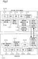
- Fig. 2 is a block diagram of a packet data communication system having communication devices according to the present invention.
- the system comprises a digital still camera 100 and a projector 200 each serving as a packet data communication device.
- Reference numeral 101 denotes a CPU which controls the whole digital still camera 100
- 102 denotes a timer having a function of making a time elapse known
- 103 denotes a ROM in which programs to be executed by the CPU 101 are stored
- 104 denotes a RAM for storing data to be used by the CPU 101
- 105 denotes a secondary storage for storing captured image data.
- reference numeral 106 denotes a user interface portion which performs things such as recognition of operations by the user, display of images, and the like
- 107 denotes a camera control portion which performs control of an image pickup device, processing of images, and the like
- 108 denotes an infrared communication control portion which performs operations such as modulation and demodulation of infrared communications
- 109 denotes an infrared transceiver portion which performs transmission and reception of infrared rays
- 110 denotes an RS232C control portion which performs operations such as modulation and demodulation of RS232C communications
- 111 denotes an RS232C connector.
- Reference numeral 201 denotes a CPU which controls the whole projector 200
- 202 denotes a timer having a function of making a time elapse known
- 203 denotes a ROM in which programs to be executed by the CPU 201 are stored
- 204 denotes a RAM for storing data to be used by the CPU 201
- 205 denotes a secondary storage for storing data to be projected onto a screen.
- reference numeral 206 denotes a user interface portion which recognizes operations by the user
- 207 denotes a projector control portion which controls the projector in color, focus, and the like
- 208 denotes a lens for outputting an image onto the screen
- 209 denotes an RS232C control portion which performs operations such as the modulation and demodulation of RS232C communications
- 210 denotes an RS232C connector.
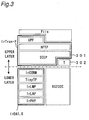
- Fig. 3 shows a protocol stack of the digital still camera in this embodiment.
- the digital still camera is equipped with a lower-layer communication section including IrDA 1.0 and RS232C, and an upper-layer communication section including IrTran-P and a T layer which has an error-detection and retransmission function.
- the T layer is capable of setting data packets to arbitrary lengths, and the error-detection and retransmission function of the T layer is realized by adding a CRC16 (Cyclic Redundancy Check-CCITT) to every packet.
- CRC16 Cyclic Redundancy Check-CCITT
- Fig. 4 shows a protocol stack of the projector in this embodiment.
- the projector is equipped with a lower-layer communication section having only RS232C, and an upper-layer communication section including IrTran-P and a T layer with an error-detection and retransmission function.
- the IrDA 1.0 comprises IrPHY, IrLAP, IrLMP, TinyTP and IrCOMM, and the IrTran-P comprises SCEP, bFTP and UPF.
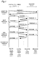
- Fig. 1 shows communication procedures for transmitting image data from the digital still camera 100 to the projector 200.
- single solid lines represent data transmission and reception within the upper-layer communication section inside each device, and double lines represent data transmission and reception between the upper-layer communication section and the lower-layer communication section, including communications between the devices.
- connection procedure 501 is performed.
- this procedure regardless of whether the lower-layer communication section has an error-detection and retransmission function or not, direct communication is performed between a digital still camera SCEP layer 301 and a projector SCEP layer 401 without using the T layers 302 and 402.
- the digital still camera SCEP layer 301 sends a connection request protocol to the projector SCEP layer 401 (Procedure 1). If the projector 200 is ready for processing, then the projector SCEP layer 401 sends a connection acceptance protocol to the digital still camera SCEP layer 301 (Procedure 2).
- the connection request and connection acceptance protocols include information as to whether each device has a T layer in the respective upper-layer communication sections. At a time point when Procedure 2 has been completed, it is decided whether or not the T layer should be used as an upper-layer communication tool.
- both the digital still camera and the projector have a T layer in the respective upper-layer communication sections
- data communication is performed through the T layers.
- both the digital still camera and the projector have the T layer 302, 402 within the respective upper-layer communication sections, as shown in Figs. 3 and 4, data communication is performed through the T layers 302 and 402.
- a query procedure 502 is performed. This procedure involves information as to parameters, such as communication speed, communication buffer size, image size, number of colors and so on, that can be dealt with by individual devices. Upon completion of the query procedure 502, those parameters to be used in the subsequent communication between the two devices are determined.
- the digital still camera SCEP layer 301 transmits image data to the digital still camera T layer 302 (Procedure 3).
- the digital still camera T layer 302 adds CRC16 to the image data in arbitrary-length packets and transmits the data to the projector T layer 402 (Procedure 4).
- the projector T layer 402 performs a CRC (cyclic redundancy check), and if it is verified that normal reception has been done without any error detection, the projector T layer 402 transmits the image data to the projector SCEP layer 401, which is an upper layer (Procedure 5). Also, the projector T layer 402 transmits data added with the CRC16 to the digital still camera T layer 302 to notify it of the fact that normal reception has been done (Procedure 6).
- the digital still camera T layer performs a CRC on received packets in Procedure 6, and if normal reception has been done, the digital still camera T layer 302 notifies the digital still camera SCEP layer 301 of the fact that Procedure 3 has been completed normally (Procedure 7).
- the projector SCEP layer 401 transmits to the projector T layer 402 response data for the image data received by Procedure 5 (Procedure 8).
- the projector T layer 402 adds CRC16 to the data in arbitrary-length packets and transmits the packets to the digital still camera T layer 302 (Procedure 9).
- the digital still camera T layer 302 performs a CRC check. As a result, if it is verified that normal reception has been done without any error detection, the digital still camera T layer 302 transmits the data to its upper layer, digital still camera SCEP layer 301 (Procedure 10).
- the digital still camera T layer 302 transmits data added with the CRC16 to the projector T layer 402 to notify it of the fact that normal reception has been done (Procedure 11).
- the projector T layer 402 performs a CRC check on received packets by Procedure 11, and if normal reception has been done, the projector T layer 402 notifies the projector SCEP layer 401 of the fact that Procedure 8 has been normally ended (Procedure 12).
- the query procedure 502 is now completed. Subsequently to this on, a data transfer procedure 503 is performed, and upon completion of the data transfer procedure, a disconnection procedure 504 is performed.
- the data transmission from the digital still camera 100 to the projector 200 is the same as Procedures 3 to 7
- the data transmission from the projector 200 to the digital still camera 100 is the same as Procedures 8 to 12. Therefore, description of these procedures is omitted.
- Fig. 5 is a flowchart of relating to the connection procedure 501, which shows a part of programs for a device having both a reliable lower-layer communication channel (IrDA 1.0 in this embodiment) and an unreliable lower-layer communication channel (RS232C in this embodiment), and including a T layer in the upper-layer communication section.
- IrDA 1.0 in this embodiment a reliable lower-layer communication channel
- RS232C unreliable lower-layer communication channel
- a communication request protocol is transmitted at step S1, and the program goes to step S2. If a packet is received at step S2, then the program goes to step S3. Otherwise, the program goes to step S4. If the received packet is a normal packet (i.e., a response packet) at step S3, then the program goes to step S6. Otherwise, the program goes to step S5. If no packets have been received within a prescribed time period, the program decides a time-out at step S4 and goes to step S5. If the prescribed time period has not elapsed, the program returns to step S2. At step S5, it is notified that the connection procedure 501 has failed, and the connection procedure 501 is ended.
- a normal packet i.e., a response packet
- step S6 if it is found out that the other station has a T layer, the program goes to step S7; if it is found out that the other station does not have a T layer, the program goes to step S8.
- step S7 it is notified that the subsequent data transmission will be performed with the T layer (that is, using a lower-layer communication section having no error-detection and retransmission function), and the connection procedure 501 ends.
- step S8 it is notified that the subsequent data transmission will be performed without the T layer (that is, using a lower-layer communication tool having an error-detection and retransmission function), and the connection procedure 501 ends.
- step S7 if the other station has a T layer, the program goes to step S7.
- the subsequent communication procedures are as described above (see Fig. 1).
- the program goes to step S8.
- the other station also needs to have a lower-layer communication section having an error-detection and retransmission function, such as IrDA 1.0. If the other station does not have a T layer within the upper-layer communication section and is provided with an unreliable lower-layer communication channel such as RS232C, then the resultant communication device as a whole will be not equipped with the error-detection and retransmission function, in which case, apparently, reliability cannot be ensured.
- communication can be performed by deciding whether or not the other station has a T layer, and by selecting a suitable lower-layer communication portion according to the decision.
Landscapes
- Engineering & Computer Science (AREA)
- Computer Networks & Wireless Communication (AREA)
- Signal Processing (AREA)
- Computer Security & Cryptography (AREA)
- Communication Control (AREA)
- Detection And Prevention Of Errors In Transmission (AREA)
- Data Exchanges In Wide-Area Networks (AREA)
Applications Claiming Priority (2)
| Application Number | Priority Date | Filing Date | Title |
|---|---|---|---|
| JP36872198A JP3567092B2 (ja) | 1998-12-25 | 1998-12-25 | パケットデータ通信装置 |
| JP36872198 | 1998-12-25 |
Publications (2)
| Publication Number | Publication Date |
|---|---|
| EP1014614A2 true EP1014614A2 (fr) | 2000-06-28 |
| EP1014614A3 EP1014614A3 (fr) | 2004-11-17 |
Family
ID=18492573
Family Applications (1)
| Application Number | Title | Priority Date | Filing Date |
|---|---|---|---|
| EP99125822A Withdrawn EP1014614A3 (fr) | 1998-12-25 | 1999-12-23 | Dispositif de transmission de paquets de données avec fonction de commande de retransmission |
Country Status (3)
| Country | Link |
|---|---|
| US (1) | US6634006B1 (fr) |
| EP (1) | EP1014614A3 (fr) |
| JP (1) | JP3567092B2 (fr) |
Families Citing this family (3)
| Publication number | Priority date | Publication date | Assignee | Title |
|---|---|---|---|---|
| TW506594U (en) * | 2001-12-11 | 2002-10-11 | Chung Shan Inst Of Science | Self-service photograph printing device |
| WO2005114855A1 (fr) * | 2004-04-29 | 2005-12-01 | Thomson Licensing S.A. | Dispositif telephonique a caracteristiques irda de l'association de transfert de donnees par l'infrarouge |
| US9575184B2 (en) | 2014-07-03 | 2017-02-21 | Continental Advanced Lidar Solutions Us, Inc. | LADAR sensor for a dense environment |
Family Cites Families (7)
| Publication number | Priority date | Publication date | Assignee | Title |
|---|---|---|---|---|
| JPH01502861A (ja) * | 1987-09-04 | 1989-09-28 | ディジタル イクイプメント コーポレーション | 多重転送プロトコルを支援するデジタル処理システム用回路網内のセッション制御 |
| US5008739A (en) * | 1989-02-13 | 1991-04-16 | Eastman Kodak Company | Real-time digital processor for producing full resolution color signals from a multi-color image sensor |
| US5548587A (en) * | 1994-09-12 | 1996-08-20 | Efficient Networks, Inc. | Asynchronous transfer mode adapter for desktop applications |
| JP3614907B2 (ja) * | 1994-12-28 | 2005-01-26 | 株式会社東芝 | データ再送制御方法及びデータ再送制御システム |
| JPH0973412A (ja) * | 1995-06-30 | 1997-03-18 | Toshiba Corp | データ転送方法及びメモリ管理装置 |
| JP2836606B2 (ja) * | 1996-10-25 | 1998-12-14 | 日本電気株式会社 | Atmセル転送装置 |
| JP3466434B2 (ja) * | 1997-09-11 | 2003-11-10 | シャープ株式会社 | 印刷制御方法及び印刷システム |
-
1998
- 1998-12-25 JP JP36872198A patent/JP3567092B2/ja not_active Expired - Fee Related
-
1999
- 1999-12-22 US US09/469,394 patent/US6634006B1/en not_active Expired - Fee Related
- 1999-12-23 EP EP99125822A patent/EP1014614A3/fr not_active Withdrawn
Non-Patent Citations (3)
| Title |
|---|
| BARKER P ET AL: "PERFORMANCE MODELING OF THE IRDA PROTOCOL FOR INFRARED WIRELESS COMMUNICATIONS" IEEE COMMUNICATIONS MAGAZINE, IEEE SERVICE CENTER. PISCATAWAY, N.J, US, vol. 36, no. 12, 1 December 1998 (1998-12-01), pages 113-117, XP000800996 ISSN: 0163-6804 * |
| INGHAM B ET AL: "INFRARED'S ROLE IN WIRELESS COMMUNICATION EXPANDS WITH IRDA" ELECTRONIC DESIGN, PENTON PUBLISHING, CLEVELAND, OH, US, vol. 45, no. 15, 21 July 1997 (1997-07-21), page 62,66,68, XP000782896 ISSN: 0013-4872 * |
| OZUGUR T ET AL: "ARQ protocol for infrared wireless LANs: packet-level ACK or no-packet-level ACK?" UNIVERSAL PERSONAL COMMUNICATIONS, 1998. ICUPC '98. IEEE 1998 INTERNATIONAL CONFERENCE ON FLORENCE, ITALY 5-9 OCT. 1998, NEW YORK, NY, USA,IEEE, US, 5 October 1998 (1998-10-05), pages 1235-1239, XP010315010 ISBN: 0-7803-5106-1 * |
Also Published As
| Publication number | Publication date |
|---|---|
| JP2000196667A (ja) | 2000-07-14 |
| JP3567092B2 (ja) | 2004-09-15 |
| US6634006B1 (en) | 2003-10-14 |
| EP1014614A3 (fr) | 2004-11-17 |
Similar Documents
| Publication | Publication Date | Title |
|---|---|---|
| KR100869540B1 (ko) | 송신기, 수신기, 통신시스템, 통신방법, 통신프로그램을 기록한 컴퓨터 독취가능한 기록매체 | |
| US7548736B2 (en) | Transmitter, receiver, data transfer system, transmission method, reception method, computer program for transmission, computer program for reception, and recording medium | |
| US6618359B1 (en) | Error recovery in a mixed protocol networks | |
| US8284684B2 (en) | Communication device, communication system, communication method, and communication circuit | |
| US8291273B2 (en) | Communication device, non-transitory computer-readable medium storing a communication program | |
| US7787391B2 (en) | Communication device, communication system, communication method, communication program, and communication circuit | |
| US7151746B2 (en) | Wireless data communication system | |
| WO2006080357A1 (fr) | Dispositif de communication, système de communication, méthode de communication, programme de communication et circuit de communication | |
| JP4597583B2 (ja) | データ送信装置、データ受信装置、通信システム、データ送信装置の制御プログラム、データ受信装置の制御プログラム、および、コンピュータ読み取り可能な記録媒体 | |
| EP0886410A2 (fr) | Procédé, dispositif et support d'enregistrement de programme pour la communication de données | |
| EP1940106B1 (fr) | Appareil de communication par infrarouge et méthode de communication par infrarouge | |
| US6634006B1 (en) | Packet data communication device | |
| US8818533B2 (en) | Information processing device, communication system, and information processing method | |
| JP2007174625A (ja) | 送信機、受信機、通信システム、通信方法、通信プログラム | |
| US20130128850A1 (en) | Wireless communication terminal | |
| WO2021218239A1 (fr) | Procédé de commutation de vitesse de transmission et appareil associé | |
| CN117134866A (zh) | 通信设备及其控制方法和非暂态计算机可读存储介质 | |
| JP4430054B2 (ja) | 通信装置、通信方法、通信プログラム、記録媒体 | |
| JP2862403B2 (ja) | データ伝送方法 | |
| KR100504843B1 (ko) | 지에스엠 시스템의 가변 플래그 길이에 의한 팩스 데이터전송방법 | |
| JP3000946B2 (ja) | ファクシミリ信号送受信回路 | |
| CN116055009A (zh) | 数据传输方法及相关装置 | |
| JP2004056780A (ja) | データ受信ノード | |
| KR19980068377A (ko) | 상위기기와 양방향 수신장치간의 정보전송 프로토콜 구현방법 | |
| JP2004032736A (ja) | データ送信ノード |
Legal Events
| Date | Code | Title | Description |
|---|---|---|---|
| PUAI | Public reference made under article 153(3) epc to a published international application that has entered the european phase |
Free format text: ORIGINAL CODE: 0009012 |
|
| AK | Designated contracting states |
Kind code of ref document: A2 Designated state(s): AT BE CH CY DE DK ES FI FR GB GR IE IT LI LU MC NL PT SE |
|
| AX | Request for extension of the european patent |
Free format text: AL;LT;LV;MK;RO;SI |
|
| PUAL | Search report despatched |
Free format text: ORIGINAL CODE: 0009013 |
|
| AK | Designated contracting states |
Kind code of ref document: A3 Designated state(s): AT BE CH CY DE DK ES FI FR GB GR IE IT LI LU MC NL PT SE |
|
| AX | Request for extension of the european patent |
Extension state: AL LT LV MK RO SI |
|
| RIC1 | Information provided on ipc code assigned before grant |
Ipc: 7H 04L 1/16 A |
|
| RIN1 | Information on inventor provided before grant (corrected) |
Inventor name: ONO, SHUICHIRO Inventor name: IKEDA, YUKATA |
|
| 17P | Request for examination filed |
Effective date: 20050316 |
|
| AKX | Designation fees paid |
Designated state(s): DE FR GB |
|
| STAA | Information on the status of an ep patent application or granted ep patent |
Free format text: STATUS: THE APPLICATION IS DEEMED TO BE WITHDRAWN |
|
| 18D | Application deemed to be withdrawn |
Effective date: 20060809 |