EP1014103B1 - System zur Bestimmung der Position - Google Patents
System zur Bestimmung der Position Download PDFInfo
- Publication number
- EP1014103B1 EP1014103B1 EP99309825A EP99309825A EP1014103B1 EP 1014103 B1 EP1014103 B1 EP 1014103B1 EP 99309825 A EP99309825 A EP 99309825A EP 99309825 A EP99309825 A EP 99309825A EP 1014103 B1 EP1014103 B1 EP 1014103B1
- Authority
- EP
- European Patent Office
- Prior art keywords
- mobile station
- base station
- distance
- pilot channel
- base stations
- Prior art date
- Legal status (The legal status is an assumption and is not a legal conclusion. Google has not performed a legal analysis and makes no representation as to the accuracy of the status listed.)
- Expired - Lifetime
Links
- 238000000034 method Methods 0.000 claims description 15
- 230000000694 effects Effects 0.000 claims description 13
- 230000001360 synchronised effect Effects 0.000 claims description 12
- 238000012935 Averaging Methods 0.000 claims 2
- 238000005259 measurement Methods 0.000 description 16
- 238000013459 approach Methods 0.000 description 8
- 238000004891 communication Methods 0.000 description 5
- 230000001413 cellular effect Effects 0.000 description 3
- 230000010363 phase shift Effects 0.000 description 3
- 238000004458 analytical method Methods 0.000 description 2
- 238000004519 manufacturing process Methods 0.000 description 2
- 238000012986 modification Methods 0.000 description 2
- 230000004048 modification Effects 0.000 description 2
- 238000009827 uniform distribution Methods 0.000 description 2
- 238000004364 calculation method Methods 0.000 description 1
- 238000006243 chemical reaction Methods 0.000 description 1
- 238000007796 conventional method Methods 0.000 description 1
- 230000001419 dependent effect Effects 0.000 description 1
- 238000001514 detection method Methods 0.000 description 1
- 238000010586 diagram Methods 0.000 description 1
- 230000009429 distress Effects 0.000 description 1
- 238000009434 installation Methods 0.000 description 1
- 238000012795 verification Methods 0.000 description 1
Images


Classifications
-
- G—PHYSICS
- G01—MEASURING; TESTING
- G01S—RADIO DIRECTION-FINDING; RADIO NAVIGATION; DETERMINING DISTANCE OR VELOCITY BY USE OF RADIO WAVES; LOCATING OR PRESENCE-DETECTING BY USE OF THE REFLECTION OR RERADIATION OF RADIO WAVES; ANALOGOUS ARRANGEMENTS USING OTHER WAVES
- G01S5/00—Position-fixing by co-ordinating two or more direction or position line determinations; Position-fixing by co-ordinating two or more distance determinations
- G01S5/0009—Transmission of position information to remote stations
- G01S5/0018—Transmission from mobile station to base station
- G01S5/0036—Transmission from mobile station to base station of measured values, i.e. measurement on mobile and position calculation on base station
-
- G—PHYSICS
- G01—MEASURING; TESTING
- G01S—RADIO DIRECTION-FINDING; RADIO NAVIGATION; DETERMINING DISTANCE OR VELOCITY BY USE OF RADIO WAVES; LOCATING OR PRESENCE-DETECTING BY USE OF THE REFLECTION OR RERADIATION OF RADIO WAVES; ANALOGOUS ARRANGEMENTS USING OTHER WAVES
- G01S5/00—Position-fixing by co-ordinating two or more direction or position line determinations; Position-fixing by co-ordinating two or more distance determinations
- G01S5/02—Position-fixing by co-ordinating two or more direction or position line determinations; Position-fixing by co-ordinating two or more distance determinations using radio waves
- G01S5/10—Position of receiver fixed by co-ordinating a plurality of position lines defined by path-difference measurements, e.g. omega or decca systems
-
- H—ELECTRICITY
- H04—ELECTRIC COMMUNICATION TECHNIQUE
- H04B—TRANSMISSION
- H04B7/00—Radio transmission systems, i.e. using radiation field
- H04B7/24—Radio transmission systems, i.e. using radiation field for communication between two or more posts
- H04B7/26—Radio transmission systems, i.e. using radiation field for communication between two or more posts at least one of which is mobile
-
- H—ELECTRICITY
- H04—ELECTRIC COMMUNICATION TECHNIQUE
- H04W—WIRELESS COMMUNICATION NETWORKS
- H04W64/00—Locating users or terminals or network equipment for network management purposes, e.g. mobility management
Definitions
- the present invention relates to determining the position of a mobile station; more specifically, to locating a mobile station using time difference of arrival (TDOA).
- TDOA time difference of arrival
- GPS global positioning system
- the GPS receiver receives a signal from satellites and determines its positions by performing TDOA calculations based on the known position of the satellites.
- the receiver is generally attached to a vehicle or boat and is provided for this single purpose.
- the expense of the GPS receivers has generally limited its purchasers to luxury vehicle, aircraft, and boat owners.
- Digital cellular/PCS phones have become a very convenient and inexpensive way for a person to communicate with other persons or communication systems from wherever the person is located. The person can also call 9-1-1 in the event of an emergency.
- wireless communication systems can not accurately determine the location of the caller without the use of satellites and GPS.
- CDMA code division multiple access
- each base station transmits a pilot channel signal, which is essentially an unmodulated pseudo-random noise (PN) sequence.
- PN pseudo-random noise
- the PN sequence comprises a sequence of PN chips, and each PN chip corresponds to a distance of about 800.4 feet.
- Each base station transmits the pilot channel signal using a different timing offset such that mobile stations can distinguish from which base station a pilot channel signal was transmitted.
- the mobile station is time synchronized with a serving base station, i.e., the base station in which the mobile station is in communication.
- the mobile searches time intervals referred to as search windows for the pilot channel signals.
- Each base station is configured to transmit its pilot channel signal such that mobile stations can expect to begin receiving no more than one pilot channel signal within each search window.
- the mobile station detects a pilot channel signal, it measures the pilot channel signal strength and records the phase of the pilot channel signal, in terms of PN chips, as the pilot channel signal arrives at the mobile station. If the pilot channel signal strength exceeds a predetermined threshold, then the base station that transmitted the pilot channel signal is "visible" to the mobile station.
- the measurements and recordings are transmitted from the mobile station to the serving base station or some other predetermined location over a reverse link.
- Conventional methods of determining a mobile station's geolocation generally require an indication of distances between at least three "visible" base stations and the mobile station.
- the distance between a base station and a mobile station is equal to the time ⁇ t i for a signal to travel from the base station to the mobile station, multiplied by a wave speed u of the signal.
- ⁇ t 1 ⁇ is a distance from the mobile station (having geographic coordinates (x 0 , y 0 )) to a first base station (having known geographic coordinates (x 1 ,y 1 ))
- ⁇ t 2 ⁇ is a distance from the mobile station to a second base station (having known geographic coordinates (x 2 ,y 2 ))
- ⁇ t distance from the mobile station to a third base sta having known geographic coordinates (x 3 , y 3 )
- a TDOA approach reduces the number of equations from three to two (equation (3) minus equation (1) and equation (2) minus equation (1)).
- the TDOA approach provides accurate location determinations if no system measurement errors or multi-path effects, described below, are present. Unfortunately, system measurement errors and multi-path effects generally exist and cause deviations from true location determinations. Therefore the above equations cannot be used directly to accurately determine the mobile station M's geolocation.
- the present invention addresses these problems by providing a local positioning system (LPS) designed to use radio propagation parameters in code-division multiple access (CDMA) forward links or time-division multiple access (TDMA) reverse links to estimate a mobile station's position.
- LPS local positioning system
- CDMA code-division multiple access
- TDMA time-division multiple access
- the LPS determines the position of the mobile using triangulation methods by minimizing two set of equations, called cost functions.
- the first set of cost functions represent distance errors from the "visible" base stations to the mobile station, and the second set of cost functions represents position errors in the location estimation of the mobile station.
- Both sets of cost functions include variables common to more than one of the cost functions within the set. The cost functions are minimized by estimating values for the unknown variables within each equation so that the distance or position errors in the set are as close to zero as possible.
- the LPS To determine the geographical coordinates of a mobile station when the distances between the mobile station and the base stations are not known, the LPS first estimates the distance from the mobile station to the base stations to mitigate the system measurement errors and multi-path effect. After the distances are estimated, the LPS estimates the geographic coordinates of the mobile station (x 0 , y 0 ), based on the estimated distances.
- the LPS is a software implementation on a computer to determine the geographic location (geolocation) of a mobile station.
- the LPS receives a data sample including information indicating arrival times of pilot channel signals at a mobile station and accesses base station information indicating the location of at least three cellular or PCS base stations to which the arrival time information is associated.
- the LPS estimates the distances from the mobile station to the base stations by minimizing a first set of equations or cost functions and estimates the geolocation of the mobile station by minimizing a second set of equations or cost functions based on the estimated distances.
- the LPS of the present invention provides the benefit of using existing equipment to provide GPS-like positioning capabilities.
- the LPS requires no additional signal detection capabilities, and only requires a minor modification to the existing wireless telephone systems. No additional hardware is needed other than the standard CDMA/TDMA system, making the LPS cost effective.
- the LPS can also solve the 9-1-1 mobile location problem for wireless CDMA/TDMA systems. Therefore, the LPS can determine the position of a person in distress from their digital phone.
- the embodiments described herein are used in a CDMA forward link triangulation (FLT) system. It is understood that the embodiments are also applicable to a TDMA reverse link triangulation (RLT) system upon synchronization of the base stations.
- FLT forward link triangulation
- RLT reverse link triangulation
- the LPS determines the geographic coordinates of the mobile station by receiving a data sample representing information regarding the mobile station, accessing base station information regarding at least three base stations, and estimating the location of the mobile station.
- the LPS determines the location of the mobile station by minimizing a first set of equations or cost functions to estimate the distances between the mobile station and base stations based on the data sample and the base station information, and then minimizing a second set of equations or cost functions to estimate the geographic coordinates of the mobile station.
- the LPS is based on TDOA which uses measured phase shift or chip offset information of the pilot channel signals transmitted from particular base stations that are "visible” to the mobile station.
- a TDOA triangulation approach requires time or propagation delay measurements from at least three "visible” base stations. If less than three base stations are “visible” to the mobile station, then the LPS will wait for a mobile station report of three "visible” base stations or adjust signal strength threshold levels to allow the mobile to recognize more pilot channel signals from other base stations. The mobile station frequently measures the pilot channel signal phases so that the location estimation can be accrued and made more precise over time.
- Fig. 1 shows a point representing mobile station M located inside a triangle of points representing "visible" base stations b 1 , b 2 and b 3 at respective distances d 1 , d 2 and d 3 from the mobile station M.
- the distances between the base stations are measured as: length b 1 b 2 between base stations b 1 and b 2 ; length b 1 b 3 between base stations b 1 and b 3 ; and length b 2 b 3 between base stations b 2 and b 3 .
- Angles ⁇ 12 , ⁇ 13 and ⁇ 23 are formed by arcs b 1 Mb 2 , b 1 Mb 3 and b 2 Mb 3 , respectively.
- Fig. 1 shows a point representing mobile station M located inside a triangle of points representing "visible" base stations b 1 , b 2 and b 3 at respective distances d 1 , d 2 and d 3 from the mobile station M.
- the distances between the base stations are measured as: length b
- angle ⁇ 23 is equal to 360 degrees minus angles ⁇ 12 and ⁇ 13 .
- Fig. 2 is similar to Fig. 1 except mobile station M is located outside triangle b 1 b 2 b 3 and angle ⁇ 23 is equal to angles ⁇ 12 plus ⁇ 13 .
- the distances between mobile station M and the visible base stations b 1 , b 2 and b 3 are estimated at step S40.
- the computer 10 calculates for distance d 1 such that a set of cost functions for distance errors are minimized and determines distances d 2 and d 3 based on the estimated distance d 1 .
- the estimation of distance d 1 and the determination of distances d 2 and d 3 based on distance d 1 will be described below.
- the LPS determines the geographic coordinates of mobile station M at S50 using TDOA.
- the LPS 1 calculates the local coordinates of the mobile station M, i.e., (x 0 , y 0 ) in relation to the serving base station b 1 , and converts the local coordinates (x 0 , y 0 ) to global latitude and longitude based on the known latitudes and longitudes of the base stations b 1 , b 2 and b 3 .
- the geolocation of the mobile station M can be reestimated and averaged to provide an even more accurate analysis.
- Step S40 Estimating distances between the mobile station and the base stations
- the two most critical system measurement errors in a TDOA approach are rounding errors in the pilot channel signal phase measurement and synchronization errors among base stations.
- the rounding error (worst case half a chip) contributes to 400.2 feet in deviation of location.
- the rounding error can be represented by random variable T 1 when satisfying a uniform distribution.
- each base station is time synchronized with the other base stations.
- Each base station could also be time synchronized using a GPS clock.
- the drifting error can be represented as a random variable T 2 , satisfying another uniform distribution.
- the influence of the error sources can be added to equal system measurement error T, which is the sum of random variables T 1 plus T 2 . Accordingly, a measured pilot channel signal phase p i is equal to a true pilot channel signal phase plus a system measurement error T.
- TDOA works best if the measurements being used are those belonging to line-of-sight (LOS) signals because a straight line is the shortest line between two points.
- LOS line-of-sight
- a single signal transmitted from any of the base stations b 1 , b 2 and b 3 may reflect off different objects such as buildings, trees and vehicles before it reaches the mobile station M, and therefore take a longer path than if the signal were a LOS signal.
- This multi-path effect causes a delay in the arrival of the signal and detrimentally affects the TDOA estimate.
- the delay in arrival time caused by a multi-path signal must be accounted for when using TDOA to determine the distance between the mobile station M and the base stations b 1 , b 2 and b 3 .
- the amount of delay differs depending on the distance and the objects located between the mobile station M and the base stations b 1 , b 2 and b 3 and is therefore very difficult to model.
- a single multi-path parameter ⁇ represents the proportional time delay caused by the multi-path effect and is modeled as a non-random parameter instead of a random number because the single multi-path parameter ⁇ must be estimated for all pilot channel signals.
- Multi-path parameter ⁇ is generally less than 1, and would equal its maximum of 1 if the mobile station M only acquired LOS signals from the visible base stations b 1 , b 2 and b 3 .
- one single multi-path parameter ⁇ is assumed which implies a homogenous multi-path effect. That is, the delay caused by the multi-path effect is assumed to be the same for each pilot channel signal even though the multi-path effect on the pilot channel signal from each of the base stations b 1 , b 2 and b 3 is different.
- a multi-path parameter ⁇ that represent a uniform extra delay can substantially alleviate the multi-path effect.
- the multi-path parameter ⁇ may be varied in a certain range defined by a model associated with typical environments such as rural, urban, suburban, highway, etc.
- Mobile station M does not know the exact time (as synchronized with GPS) that the base station b i transmits a pilot channel signal nor the exact time that the mobile station M receives the pilot channel signal in order to determine the time that it takes for the pilot channel signal to travel from the base station b i to the mobile station M. Therefore the distances d 1 , d 2 and d 3 between the base stations b i and the mobile station M are unknown.
- the base stations are synchronized with each other, and the mobile station M is synchronized with the serving base station b 1 .
- the mobile station M can record chip offsets of pilot channel signal phases emitted from remote base stations b 2 and b 3 in relation to the pilot channel signal of the serving base station b 1 . Therefore, the mobile M can determine the additional time - after receipt of the pilot channel signal from the serving base station b 1 - required for the pilot channel signals to travel from the remote base stations b 2 and b 3 to the mobile station M because the phase of the remote base stations b 2 and b 3 are measurable in relation to the phase of the serving base station b 1 , which is set to zero due to the synchronization of the mobile station M with the base station b 1 .
- the mobile station M identifies a pilot channel signal phase p 2 as a phase difference between the pilot channel signal phase recordings of base stations b 1 and b 2 , and identifies a pilot channel signal phase p 3 as a phase difference between the pilot channel signal phase recordings of base stations b 1 and b 3 .
- distance d 1 must be estimated before distances d 2 and d 3 can be determined.
- the LPS 1 estimates distance d 1 .
- the following equations (6)-(8) are cost functions that are minimized for distance errors F 12 , F 13 , and F 23 :
- F 12 b 1 ⁇ b 2 2 - ⁇ 2 ⁇ d 1 2 - ⁇ 2 ⁇ d 2 2 + 2 ⁇ ⁇ 2 d 1 ⁇ d 2 ⁇ cos ⁇ 12
- F 13 b 1 ⁇ b 3 2 - ⁇ 2 ⁇ d 1 2 - ⁇ 2 ⁇ d 3 2 + 2 ⁇ ⁇ 2 d 1 ⁇ d 3 ⁇ cos ⁇ 13
- F 23 b 2 ⁇ b 3 2 - ⁇ 2 ⁇ d 2 2 - ⁇ 2 ⁇ d 3 2 + 2 ⁇ ⁇ 2 d 2 ⁇ d 3 ⁇ cos ⁇ 23 for distance d 1 , multi-path parameter ⁇ and angles ⁇ , and substituting for distances d
- the minimization of cost functions F 12 , F 13 , and F 23 can be accomplished using well known minimization approaches, such as by steepest decent or incremental search with respect to d 1 .
- the above cost functions can be minimized by estimating a range for the distance d 1 and the multi-path parameter ⁇ , solving the equations (6)-(8) for each predetermined increment in the ranges, and selecting the distance d 1 , multi-path parameter ⁇ and angles ⁇ 12 , ⁇ 13 and ⁇ 23 that provide the distance errors F 12 , F 13 and F 23 closest to zero.
- distances d 2 and d 3 can be determined using equations (4) and (5).
- Equations (6)-(8) have four unknown values, namely distance d 1 , the multi-path parameter ⁇ , and angles ⁇ 12 and ⁇ 13 .
- angle ⁇ 23 is equal to 360 degrees minus angles ⁇ 12 and ⁇ 13 when the mobile station M is located inside triangle b 1 b 2 b 3 .
- Angle ⁇ 23 is equal to angles ⁇ 12 plus ⁇ 13 when mobile station M is located outside triangle b 1 b 2 b 3 .
- the angles ⁇ 12 and ⁇ 13 are determined based on the estimated distance d 1 , in other words the values of the angles ⁇ 12 and ⁇ 13 are determined according the value of distance d 1 .
- CDMA and TDMA systems can measure a round trip delay of a pilot channel signal emitted from the serving base station b 1 to the mobile station M and back to the serving base station b 1 .
- This round trip delay provides the benefit of allowing the LPS 1 to use a more narrow scope for estimating the range of distance d 1 .
- Step S50 Determining the geolocation of the mobile station
- the mobile station M Cartesian coordinates (x 0 , y 0 ) can be estimated by minimizing equations (9)-(11) for cost functions G 1 , G 2 and G 3 :
- G 1 ⁇ 2 ⁇ d 1 2 - ⁇ x 1 - x 0 2 + y 1 - y 0 2 ⁇
- G 2 ⁇ 2 ⁇ d 2 2 - ⁇ x 2 - x 0 2 + y 2 - y 0 2 ⁇
- G 3 ⁇ 2 ⁇ d 3 2 - ⁇ x 3 - x 0 2 + y 3 - y 0 2 ⁇
- G i , i 1, 2, and 3 represents the position error and is zero in an ideal case.
- equations (7-9) will not be solved exactly, but the best estimate of (x 0 0 .
- the mobile station M is synchronized with the base stations. Consequently, in the mobile station M reply message that is sent back to base station b 1 , the phase shift of the reference pilot channel signal transmitted by base station b 1 is set to zero.
- the pilot channel signal phases from base stations b 2 and b 3 are recorded in chip off-sets from the zero phase shift of base station b 1 . Accordingly, once distance d 1 is estimated, distances d 2 and d 3 can be determined directly as discussed above.
- the LPS 1 gathers input information including mobile station M information and base station b 1 , b 2 and b 3 information.
- the mobile station M records pilot channel signals emitted from base station b 1 with a base station identifying pilot PN of 432 and a pilot channel signal strength of 17 (-8.5 dB); from base station b 2 with a base station identifying pilot PN of 76, a pilot channel signal phase p 2 equal to 4 PN chips, and a pilot channel signal strength of 21 (-10.5 dB); and from base station b 3 with a base station identifying pilot PN of 220, a pilot channel signal phase p 2 equal to 3 PN chips, and a pilot channel signal strength of 19 (-9.5 dB).
- the pilot PNs that are reported by the mobile station M are matched with pilot PNs in the sector information stored in a cell site table to determine from which base stations b 1 , b 2 and b 3 the pilot channel signals were sent.
- base station b 1 is cell number 138, transmitting a pilot PN of 432 and is located at latitude 40.861389 and longitude -73.864167;
- base station b 2 is cell number 140, transmitting a pilot PN of 76 and is located at latitude 40.867500 and longitude 73.884722;
- base station b 3 is cell number 43, transmitting a pilot PN of 220 and is located at latitude 40.878889 and longitude - 73.871389.
- the base station latitudes and longitudes are converted into a local coordinate system (x,y).
- Base station b 1 's coordinates (0,0) are set as the origin
- base station b 2 's coordinates (x 2 ,0) are set to be on the x-axis
- base station b 3 's coordinates (x 3 , y 3 ) are determined from the known distances among the base stations.
- distances d 2 and d 3 are determined directly as described above to equal 0.983620 miles and 0.839603 miles, respectively.
- equations (9)-(11) are then minimized to determine that the local Cartesian coordinates (x 0 , y 0 ) equal (0.237018, 0.357580).
- These coordinates can be converted back to latitude and longitude so that the mobile station M's location can be more easily marked on a map to show which street it is located.
- the local Cartesian coordinates (0.237018, 0.357580) of the mobile station M's geographic location are converted to latitude 40.867465 and longitude -73.865885.
- angle ⁇ 13 is equal to angle ⁇ 12 plus angle ⁇ 23 . Therefore the mobile station M is not located within triangle b 1 b 2 b 3 , but instead is located outside of length b 1 b 3 .
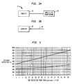
- the lower line in Fig. 5 shows an example of distance deviation (ft) between the true location and LPS estimated location of mobile station M based on the time deviation ( ⁇ s) caused by system measurement errors, including rounding errors in the pilot channel signal phase measurement and synchronization errors.
- the upper line represents the maximum error for performance over a snapshot of time. If a snapshot is extended over time and the distance deviations are averaged, the distance deviation would become the lower mean error line. Accordingly, if the base stations are synchronized, the rounding error in pilot channel signal phase measurement alone approaches 200 feet.
- the time arrival is obtained at the base stations rather than at the mobile stations.
- the mobile station transmits a coded digital verification color code (CDVCC) signal as the identity of the mobile station.
- CDVCC coded digital verification color code
- the receiving base station time stamps the time of receiving the CDVCC signal. If the base stations are synchronized, then the base stations determine the relative time differences between arrival of the CDVCC signals by subtracting the time of the receipt of the signal at the first base station from the time of the later received signals at other base stations. Accordingly, the LPS is applicable to both CDMA and TDMA systems.
- equations (6)-(11) can also be applied to TDMA RLT geolocation systems if the clock signals or base stations involved in locating a particular mobile station are synchronized.
- the synchronization could be done by installation of GPS.
- Reverse link signals are transmitted from mobile stations to base stations through the reverse link, which is generally a different frequency band than the forward link of CDMA systems, but in a same frequency band and different time slots for TDMA systems.
- a TDMA reverse link would provide the benefits of better location accuracy if the time arrival is measured at the base stations because there would be no chip-rounding error as in a CDMA forward link.
- the power control in TDMA is not as stringent as in CDMA, therefore making it easier for several base station to "see" signals from the mobile.
- Inputs needed by TDMA reverse link triangulation include the identity of the mobile requesting location service, the relative time arrivals at the base stations, location (latitude/longitude) of all base stations, and the roundtrip delay (measured continuously in TDMA for time alignment purposes). The strength of signal from the mobile station is also desired and can be measured at neighboring base stations for assistance of handoff.
Landscapes
- Engineering & Computer Science (AREA)
- Physics & Mathematics (AREA)
- General Physics & Mathematics (AREA)
- Radar, Positioning & Navigation (AREA)
- Remote Sensing (AREA)
- Computer Networks & Wireless Communication (AREA)
- Signal Processing (AREA)
- Position Fixing By Use Of Radio Waves (AREA)
- Mobile Radio Communication Systems (AREA)
- Navigation (AREA)
Claims (23)
- Verfahren zur Bestimmung der Position einer Mobilstation, die folgenden Schritte umfassend:a) Empfangen von Pilotkanal-Signalinformationen, welche die Ankunftszeiten von Pilotkanal-Signalen an der Mobilstation angeben;b) Schätzen einer Entfernung von der Mobilstation zu einer der Mehrzahl von Basisstationen (S40) durch Minimieren eines Satzes von Entfernungsfehler-Kostenfunktionen einschließlich (i) der von Verbindungen zwischen den Basisstationen und der Mobilstation gebildeten Winkel, (ii) mindestens einer Entfernung zwischen der Mobilstation und mindestens einer der Mehrzahl von Basisstationen, und (iii) eines Mehrpfadparameters; undc) Schätzen der Position der Mobilstation (S50) durch Minimieren eines Satzes von Positionsfehler-Kostenfunktionen auf der Basis der in Schritt b) erhaltenen Schätzung der Entfernung, wobei die Pilotkanal-Signalinformationen und die Basisstationsinformationen die Position der Mehrzahl von Basisstationen, welchen die Ankunftszeitinformationen zugeordnet sind, angeben.
- Das Verfahren nach Anspruch 1, wobei die Positionsfehler-Kostenfunktionen aus den folgenden Gleichungen abgeleitet werden:


wobei µ ein Mehrpfad-Effektparameter ist, d1 eine Entfernung von der Mobilstation zu einer ersten Basisstation ist, d2 eine Entfernung von der Mobilstation zu einer zweiten Basisstation ist, d3 eine Entfernung von der Mobilstation zu einer dritten Basisstation ist, (x0, y0) die lokalen kartesischen Koordinaten der Mobilstation sind, (x1, y1) die lokalen kartesischen Koordinaten der ersten Basisstation sind, (x2, y2) die lokalen kartesischen Koordinaten der zweiten Basisstation sind, und (x3, y3) die lokalen kartesischen Koordinaten der dritten Basisstation sind. - Das Verfahren nach Anspruch 2, wobei
d2 = d1 + 800.4(p2)ft, wobei p2 eine Phasendifferenz zwischen den Pilotkanal-Signalphasenaufzeichnungen der ersten und der zweiten Basisstation ist, und
d3 = d1 + 800.4(p3)ft, wobei p3 eine Phasendifferenz zwischen den Pilotkanal-Signalphasenaufzeichnungen der ersten und der dritten Basisstation ist. - Das Verfahren nach Anspruch 1, vor Schritt (b) weiterhin die folgenden Schritte umfassend:e) Empfangen der Basisstationsinformationen, welche die Position der Mehrzahl von Basisstationen angeben; undf) Abgleichen der Pilotkanal-Signalinformationen mit den Basisstationsinformationen (S30) auf der Basis einer Quellenkennung, welche den Pilotkanal-Signalinformationen und den Basisstationsinformationen gemein ist.
- Das Verfahren nach Anspruch 1, wobei die Ankunftszeiten der synchronisierten Zeitsteuerung der Basisstationen entsprechen.
- Das Verfahren nach Anspruch 1, wobei die Entfernungsfehler-Kostenfunktionen aus den folgenden Gleichungen abgeleitet werden:


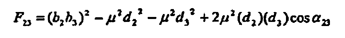
wobei b1b2 eine Entfernung von einer ersten Basisstation zu einer zweiten Basisstation ist, b1b3 eine Entfernung von der ersten Basisstation zu einer dritten Basisstation ist, b2b3 eine Entfernung von der zweiten Basisstation zu der dritten Basisstation ist, µ ein Mehrpfad-Effektparameter ist, d1 eine Entfernung von der Mobilstation zu der ersten Basisstation ist, d2 eine Entfernung von der Mobilstation zu der zweiten Basisstation ist, d3 eine Entfernung von der Mobilstation zu der dritten Basisstation ist, α12 den von Verbindungen zwischen der Mobilstation und einer ersten und einer zweiten Basisstation gebildeten Winkel kennzeichnet, α13 den von Verbindungen zwischen der Mobilstation und der ersten und einer dritten Basisstation gebildeten Winkel kennzeichnet, und α23 den von Verbindungen zwischen der Mobilstation und der zweiten und der dritten Basisstation gebildeten Winkel kennzeichnet. - Das Verfahren nach Anspruch 1, wobei die Pilotkanal-Signalinformationen mindestens entweder eine Quellenkennung, eine Pilotkanal-Signalphase oder eine Pilotstärke enthalten.
- Das Verfahren nach Anspruch 7, wobei die Basisstationsinformationen mindestens entweder eine Quellenkennung oder eine Position der Basisstation enthalten.
- Das Verfahren nach Anspruch 1, weiterhin umfassend den Schritt der Mittelung der Schätzung der Position der Mobilstation mit einer vorherigen Schätzung der Mobilstation, um einen Mittelwert der Schätzung der Position der Mobilstation zu erhalten.
- Das Verfahren nach Anspruch 1, wobei die Pilotkanal-Signalinformationen in einem CDMA-Signal enthalten sind.
- Das Verfahren nach Anspruch 1, wobei die Pilotkanal-Signalinformationen in einem TDMA-Signal enthalten sind.
- Ein auf einem Computer implementiertes System zur Bestimmung der Position einer Mobilstation, umfassend:Mittel zum Empfangen von Pilotkanal-Signalinformationen, welche die Ankunftszeiten von Pilotkanal-Signalen an der Mobilstation angeben;Mittel zum Schätzen der Entfernung von der Mobilstation zu einer der Basisstationen (S40) durch Minimieren eines Satzes von Entfernungsfehler-Kostenfunktionen einschließlich (i) von Verbindungen zwischen den Basisstationen und der Mobilstation gebildete Winkel, (ii) mindestens einer Entfernung zwischen der Mobilstation und mindestens einer der Mehrzahl von Basisstationen, und (iii) eines Mehrpfadparameters; undMittel zum Schätzen der Position der Mobilstation durch Minimieren eines Satzes von Positionsfehler-Kostenfunktionen auf der Basis der Entfernung zwischen der Mobilstation und der mindestens einen der Mehrzahl von Basisstationen, wobei die Pilotkanal-Signalinformationen und die Basisstationsinformationen die Position einer Mehrzahl von Basisstationen, welchen die Ankunftszeitinformationen zugeordnet werden, angeben.
- Das System zur Bestimmung der Position nach Anspruch 12, wobei die Positionsfehler-Kostenfunktionen aus den folgenden Gleichungen abgeleitet werden:


wobei µ ein Mehrpfad-Effektparameter ist, d1 eine Entfernung von der Mobilstation zu einer ersten Basisstation ist, d2 eine Entfernung von der Mobilstation zu einer zweiten Basisstation ist, d3 eine Entfernung von der Mobilstation zu einer dritten Basisstation ist, (x0, y0) die lokalen kartesischen Koordinaten der Mobilstation sind, (x1, y1) die lokalen kartesischen Koordinaten der ersten Basisstation sind, (x2, y2) die lokalen kartesischen Koordinaten der zweiten Basisstation sind, und (x3, y3) die lokalen kartesischen Koordinaten der dritten Basisstation sind. - Das System zur Bestimmung der Position nach Anspruch 13, wobei
d2 = d1 + 800.4(p2)ft, wobei p2 eine Phasendifferenz zwischen den Pilotkanal-Signalphasenaufzeichnungen der ersten und der zweiten Basisstation ist, und
d3 = d1 + 800.4(p3)ft, wobei p3 eine Phasendifferenz zwischen den Pilotkanal-Signalphasenaufzeichnungen der ersten und der dritten Basisstation ist. - Das System zur Bestimmung der Position nach Anspruch 12, weiterhin umfassend:Mittel zum Empfangen der Basisstationsinformationen, welche die Position der Mehrzahl von Basisstationen angeben; undMittel zum Abgleichen der Pilotkanal-Signalinformationen mit den Basisstationsinformationen (S30) auf der Basis einer Quellenkennung, welche den Pilotkanal-Signalinformationen und den Basisstationsinformationen gemein ist.
- Das System zur Bestimmung der Position nach Anspruch 13, wobei die Ankunftszeiten der synchronisierten Zeitsteuerung der Basisstationen entsprechen.
- Das System zur Bestimmung der Position nach Anspruch 12, wobei die Entfernungsfehler-Kostenfunktionen aus den folgenden Gleichungen abgeleitet werden:


wobei b1b2 eine Entfernung von einer ersten Basisstation zu einer zweiten Basisstation ist, b1b3 eine Entfernung von der ersten Basisstation zu einer dritten Basisstation ist, b2b3 eine Entfernung von der zweiten Basisstation zu der dritten Basisstation ist, µ ein Mehrpfad-Effektparameter ist, d1 eine Entfernung von der Mobilstation zu der ersten Basisstation ist, d2 eine Entfernung von der Mobilstation zu der zweiten Basisstation ist, d3 eine Entfernung von der Mobilstation zu der dritten Basisstation ist, α12 den von Verbindungen zwischen der Mobilstation und einer ersten und einer zweiten Basisstation gebildeten Winkel kennzeichnet, α13 den von Verbindungen zwischen der Mobilstation und der ersten und einer dritten Basisstation gebildeten Winkel kennzeichnet, und α23 den von Verbindungen zwischen der Mobilstation und der zweiten und der dritten Basisstation gebildeten Winkel kennzeichnet. - Das System zur Bestimmung der Position nach Anspruch 12, wobei die Pilotkanal-Signalinformationen mindestens entweder eine Quellenkennung, eine Pilotkanal-Signalphase oder eine Pilotstärke enthalten.
- Das System zur Bestimmung der Position nach Anspruch 18, wobei die Basisstationsinformationen mindestens entweder eine Quellenkennung oder eine Position der Basisstation enthalten.
- Das System zur Bestimmung der Position nach Anspruch 12, weiterhin umfassend Mittel zur Mittelung der Schätzung der Position der Mobilstation mit einer vorherigen Schätzung der Mobilstation, um einen Mittelwert der Schätzung der Position der Mobilstation zu erhalten.
- Das System zur Bestimmung der Position nach Anspruch 12, wobei die Pilotkanal-Signalinformationen in einem CDMA-Signal enthalten sind.
- Das System zur Bestimmung der Position nach Anspruch 12, wobei die Pilotkanal-Signalinformationen in einem TDMA-Signal enthalten sind.
- Ein auf einem computerlesbaren Medium verkörpertes ausführbares Programm zur Bestimmung der Position einer Mobilstation, umfassend:Ein Quellcode-Empfangssegment zum Empfangen von Pilotkanal-Signalinformationen, welche die Ankunftszeiten von Pilotkanal-Signalen an der Mobilstation angeben;ein Quellcode-Berechnungssegment zum Schätzen einer Entfernung von der Mobilstation zu einer der Basisstationen (S40) durch Minimieren eines Satzes von Entfernungsfehler-Kostenfunktionen einschließlich (i) der von Verbindungen zwischen den Basisstationen und der Mobilstation gebildeten Winkel, (ii) mindestens einer Entfernung zwischen der Mobilstation und mindestens einer der Mehrzahl von Basisstationen, und (iii) eines Mehrpfadparameters; undein Quellcode-Schätzungssegment zum Schätzen der Position der Mobilstation (S50) durch Minimieren eines Satzes von Positionsfehler-Kostenfunktionen auf der Basis der Entfernung zwischen der Mobilstation und der mindestens einen der Mehrzahl von Basisstationen, wobei die Pilotkanal-Signalinformationen und die Basisstationsinformationen die Position einer Mehrzahl von Basisstationen, welchen die Ankunftszeitinformationen zugeordnet werden, angeben.
Applications Claiming Priority (2)
| Application Number | Priority Date | Filing Date | Title |
|---|---|---|---|
| US212261 | 1998-12-16 | ||
| US09/212,261 US6748224B1 (en) | 1998-12-16 | 1998-12-16 | Local positioning system |
Publications (3)
| Publication Number | Publication Date |
|---|---|
| EP1014103A2 EP1014103A2 (de) | 2000-06-28 |
| EP1014103A3 EP1014103A3 (de) | 2002-03-20 |
| EP1014103B1 true EP1014103B1 (de) | 2011-04-06 |
Family
ID=22790272
Family Applications (1)
| Application Number | Title | Priority Date | Filing Date |
|---|---|---|---|
| EP99309825A Expired - Lifetime EP1014103B1 (de) | 1998-12-16 | 1999-12-07 | System zur Bestimmung der Position |
Country Status (8)
| Country | Link |
|---|---|
| US (1) | US6748224B1 (de) |
| EP (1) | EP1014103B1 (de) |
| JP (1) | JP3510549B2 (de) |
| KR (1) | KR20000062203A (de) |
| CN (1) | CN1257387A (de) |
| BR (1) | BR9905822A (de) |
| CA (1) | CA2288490A1 (de) |
| DE (1) | DE69943332D1 (de) |
Families Citing this family (84)
| Publication number | Priority date | Publication date | Assignee | Title |
|---|---|---|---|---|
| US6393294B1 (en) * | 1998-09-22 | 2002-05-21 | Polaris Wireless, Inc. | Location determination using RF fingerprinting |
| JP3573052B2 (ja) * | 2000-02-22 | 2004-10-06 | 株式会社日立製作所 | 無線端末位置測定装置 |
| JP3673700B2 (ja) * | 2000-06-27 | 2005-07-20 | 株式会社日立製作所 | スペクトル拡散信号を用いた測距及び位置測定方法、その方法を行う装置 |
| JP2002024997A (ja) * | 2000-07-12 | 2002-01-25 | Nec Corp | 行き先案内システム |
| JP2002034068A (ja) * | 2000-07-18 | 2002-01-31 | Pioneer Electronic Corp | 移動体通信システムと移動局及び基地局 |
| JP2002033699A (ja) * | 2000-07-18 | 2002-01-31 | Pioneer Electronic Corp | 移動体通信システム |
| US6658258B1 (en) | 2000-09-29 | 2003-12-02 | Lucent Technologies Inc. | Method and apparatus for estimating the location of a mobile terminal |
| JP3540754B2 (ja) * | 2001-02-06 | 2004-07-07 | 株式会社日立製作所 | 位置算出方法、位置算出装置及びそのプログラム |
| JP3461167B2 (ja) | 2001-02-07 | 2003-10-27 | 株式会社日立製作所 | 位置計算方法及び位置算出装置 |
| JP3746210B2 (ja) * | 2001-07-19 | 2006-02-15 | 株式会社日立製作所 | 位置測定システムおよび位置測定方法 |
| JP2003035553A (ja) * | 2001-07-25 | 2003-02-07 | Nec Corp | 位置情報変換装置及びその方法、位置関連情報提供サーバ並びに位置関連情報提供システム |
| US6941144B2 (en) | 2001-09-14 | 2005-09-06 | Qualcomm Incorporated | Method and apparatus for detecting excess delay in a communication signal |
| FI110455B (fi) * | 2001-09-17 | 2003-01-31 | Nokia Corp | Menetelmä sijainninmäärityksen suorittamiseksi ja elektroniikkalaite |
| US20030114170A1 (en) * | 2001-12-14 | 2003-06-19 | Rick Roland R. | Position determination system that uses a cellular communication system |
| US7136659B2 (en) | 2002-03-19 | 2006-11-14 | Qualcomm, Incorporated | Update of base station identifiers based on overhead visit |
| US20040203845A1 (en) * | 2002-03-22 | 2004-10-14 | Lal Amrish K. | Method and system for associating location specific data with data in a mobile database |
| KR100465035B1 (ko) * | 2002-04-29 | 2005-01-06 | 에스케이 텔레콤주식회사 | 패킷 기반 이동통신망에서 이동 단말기 위치 예측 방법 |
| US7751825B2 (en) * | 2002-06-27 | 2010-07-06 | Qualcomm Incorporated | Controlling geographic location information of devices operating in wireless communication systems |
| CN1298188C (zh) * | 2002-08-31 | 2007-01-31 | 中兴通讯股份有限公司 | 一种基于现有通讯协议的定位方法 |
| US20040203872A1 (en) * | 2002-09-04 | 2004-10-14 | Bajikar Sundeep M. | Wireless network location estimation |
| KR100541342B1 (ko) * | 2002-10-15 | 2006-01-10 | 주식회사 엠에스피테크놀로지 | 이동단말기의 위치 추적을 위한 칩 딜레이 획득 방법 |
| CN100536594C (zh) * | 2002-12-02 | 2009-09-02 | 诺基亚公司 | 信号延迟的估计 |
| BRPI0317181B1 (pt) * | 2002-12-13 | 2016-10-18 | Qualcomm Inc | sistema de calibragem e correção para sistemas de localização de posição por satélite |
| US8483717B2 (en) * | 2003-06-27 | 2013-07-09 | Qualcomm Incorporated | Local area network assisted positioning |
| JP4865553B2 (ja) * | 2003-07-23 | 2012-02-01 | クゥアルコム・インコーポレイテッド | 無線通信システムにおいて、デバイスの位置決めに用いられるナビゲーション解を選択すること |
| US7092726B2 (en) * | 2003-12-29 | 2006-08-15 | Motorola, Inc. | Method and system for determining a location using a plurality of selected initial location estimates |
| US7599698B2 (en) * | 2003-12-29 | 2009-10-06 | Telefonaktiebolaget Lm Ericsson (Publ) | Network controlled channel information reporting |
| KR100573203B1 (ko) * | 2004-03-17 | 2006-04-24 | 에스케이 텔레콤주식회사 | 지피에스 전파 음영 지역에서 위치 탐색기를 이용하여단말기의 위치를 측위하는 방법 및 시스템 |
| US20050227703A1 (en) * | 2004-03-30 | 2005-10-13 | Cheng Steven D | Method for using base station power measurements to detect position of mobile stations |
| DE102004025129A1 (de) * | 2004-05-14 | 2005-12-08 | Siemens Ag | Verfahren zur Lokalisierung eines Mobilfunkendgerätes in einem Mobilfunknetz |
| US20060095234A1 (en) * | 2004-10-29 | 2006-05-04 | Cyril Brignone | Converting between coordinate systems |
| DE102004059957A1 (de) * | 2004-12-13 | 2006-06-14 | Fraunhofer-Gesellschaft zur Förderung der angewandten Forschung e.V. | Synchronisationsvorrichtung und Vorrichtung zum Erzeugen eines Synchronisationssignals |
| KR100605980B1 (ko) | 2005-01-04 | 2006-07-31 | 삼성전자주식회사 | 휴대 인터넷 신호를 이용한 위치 측정 시스템 및 방법 |
| US20060244461A1 (en) * | 2005-01-19 | 2006-11-02 | Yuh-Shen Song | Intelligent portable personal communication device |
| US8355737B2 (en) * | 2005-03-18 | 2013-01-15 | Wavemarket, Inc. | Enhanced mobile location |
| MX2007011393A (es) * | 2005-03-18 | 2008-03-11 | Seeker Wireless Pty Lilmited | Metodo y sistema para la localizacion movil mejorada. |
| WO2006105619A1 (en) * | 2005-04-08 | 2006-10-12 | Seeker Wireless Pty Limited | Mobile location |
| US7636061B1 (en) | 2005-04-21 | 2009-12-22 | Alan Thomas | Method and apparatus for location determination of people or objects |
| US20060264223A1 (en) * | 2005-05-23 | 2006-11-23 | Lucent Technologies Inc. | System and method for providing travel information to a mobile terminal in a wireless telecommunications network |
| US8056800B2 (en) * | 2005-06-30 | 2011-11-15 | The Boeing Company | Systems and methods for configuration management |
| RU2008120686A (ru) * | 2005-10-24 | 2009-12-10 | Сикер Уайрлесс Пти Лимитед (Au) | Обнаружение при эксплуатационной поддержке мобильной связи |
| WO2007051223A1 (en) * | 2005-11-04 | 2007-05-10 | Seeker Wireless Pty Limited | Profile based communications service |
| JP2007251357A (ja) * | 2006-03-14 | 2007-09-27 | Fujitsu Ltd | 緊急通報システム及びその方法 |
| US7880676B2 (en) * | 2006-04-19 | 2011-02-01 | Wichorus Inc. | Method and system for hybrid positioning using partial distance information |
| US7577446B2 (en) * | 2006-08-03 | 2009-08-18 | Ntt Docomo, Inc. | Weighted least square localization method exploiting multipath channel statistics for non-line-of-sight mitigation |
| US8731146B2 (en) | 2007-01-04 | 2014-05-20 | At&T Intellectual Property I, L.P. | Call re-directed based on voice command |
| KR100838471B1 (ko) | 2007-02-12 | 2008-06-16 | 주식회사 케이티프리텔 | 동기식 cdma 가입자 단말의 위치 측정 장치 및 그 측정방법 |
| WO2008109948A1 (en) * | 2007-03-13 | 2008-09-18 | Seeker Wireless Pty Limited | Enhanced zone determination |
| JP2010529419A (ja) * | 2007-05-01 | 2010-08-26 | クゥアルコム・インコーポレイテッド | ワイヤレス通信システムの位置特定 |
| US8412227B2 (en) | 2007-05-18 | 2013-04-02 | Qualcomm Incorporated | Positioning using enhanced pilot signal |
| US9119026B2 (en) | 2007-05-18 | 2015-08-25 | Qualcomm Incorporated | Enhanced pilot signal |
| US8027761B1 (en) | 2007-09-04 | 2011-09-27 | Nelson Russell G | Local positioning system for automated lawn mowers |
| EP2191681A4 (de) * | 2007-09-17 | 2012-04-18 | Wavemarket Inc D B A Location Labs | Systeme und verfahren zum triggern von auf dem ort basierender sprach- und/oder datenkommunikation zu oder von mobilfunkendgeräten |
| US8737985B2 (en) * | 2007-11-26 | 2014-05-27 | Wavemarket, Inc. | Methods and systems for zone creation and adaption |
| US20100195553A1 (en) | 2008-03-18 | 2010-08-05 | Myers Theodore J | Controlling power in a spread spectrum system |
| US7773664B2 (en) * | 2008-03-18 | 2010-08-10 | On-Ramp Wireless, Inc. | Random phase multiple access system with meshing |
| US20090239550A1 (en) * | 2008-03-18 | 2009-09-24 | Myers Theodore J | Random phase multiple access system with location tracking |
| US7733945B2 (en) * | 2008-03-18 | 2010-06-08 | On-Ramp Wireless, Inc. | Spread spectrum with doppler optimization |
| US8477830B2 (en) | 2008-03-18 | 2013-07-02 | On-Ramp Wireless, Inc. | Light monitoring system using a random phase multiple access system |
| US8958460B2 (en) | 2008-03-18 | 2015-02-17 | On-Ramp Wireless, Inc. | Forward error correction media access control system |
| US8520721B2 (en) | 2008-03-18 | 2013-08-27 | On-Ramp Wireless, Inc. | RSSI measurement mechanism in the presence of pulsed jammers |
| US7782926B2 (en) | 2008-03-18 | 2010-08-24 | On-Ramp Wireless, Inc. | Random phase multiple access communication interface system and method |
| US20110034179A1 (en) * | 2008-04-07 | 2011-02-10 | Seeker Wireless Pty. Limited | Location of wireless mobile terminals |
| US8781505B2 (en) * | 2008-08-29 | 2014-07-15 | Qualcomm Incorporated | Location determination of mobile device |
| US20100167728A1 (en) * | 2008-12-31 | 2010-07-01 | Motorola, Inc. | Apparatus and method for femto cell coverage mapping using macro base station |
| US8363699B2 (en) | 2009-03-20 | 2013-01-29 | On-Ramp Wireless, Inc. | Random timing offset determination |
| US7639726B1 (en) | 2009-03-20 | 2009-12-29 | On-Ramp Wireless, Inc. | Downlink communication |
| US7702290B1 (en) | 2009-04-08 | 2010-04-20 | On-Ramp Wirless, Inc. | Dynamic energy control |
| US8463292B2 (en) * | 2009-06-29 | 2013-06-11 | Telefonaktiebolaget Lm Ericsson (Publ) | TDOA—based reconstruction of base station location data |
| US8730932B2 (en) | 2009-08-05 | 2014-05-20 | Andrew Llc | System and method for hybrid location in a CDMA 2000 network |
| US9081078B2 (en) * | 2010-02-02 | 2015-07-14 | Alcatel Lucent | Technique for effectively communicating location information in a wireless communication service |
| US8244236B2 (en) | 2010-04-29 | 2012-08-14 | Wavemarket, Inc. | System and method for aggregating and disseminating mobile device tag data |
| EP2372386B1 (de) * | 2010-03-24 | 2014-07-23 | Xiaoyun Li | Verfahren zur Abstandsschätzung |
| US8504077B2 (en) | 2010-12-04 | 2013-08-06 | Wavemarket, Inc. | System and method for monitoring and disseminating mobile device location information |
| DE102011016905A1 (de) * | 2011-01-04 | 2012-07-05 | Nokia Siemens Networks Oy | Bestimmung des Ortes von Endgeräten in Mobilfunknetzen |
| KR101231983B1 (ko) * | 2011-06-28 | 2013-02-08 | 엘에스산전 주식회사 | 실시간 위치추적 시스템의 동기 획득 방법 |
| US9107043B2 (en) * | 2013-09-30 | 2015-08-11 | Qualcomm Incorporated | Determining coordinates of access points in an indoor position location system |
| US9885772B1 (en) * | 2014-08-26 | 2018-02-06 | Vencore Labs, Inc. | Geolocating wireless emitters |
| EP3032279B1 (de) | 2014-12-08 | 2019-03-20 | Fraunhofer-Gesellschaft zur Förderung der angewandten Forschung e.V. | Pseudoentfernungsdeterminator, Verfahren zur Bereitstellung von Pseudoentfernungsinformation und Computerprogramm |
| CN105828199A (zh) * | 2016-05-05 | 2016-08-03 | 北京思特奇信息技术股份有限公司 | 一种机顶盒的定位方法及系统 |
| DE102016012101A1 (de) | 2016-10-08 | 2018-04-12 | Forschungszentrum Jülich GmbH | Verfahren und Vorrichtung zur Positionsbestimmung |
| WO2020065894A1 (ja) * | 2018-09-27 | 2020-04-02 | 三菱電機株式会社 | 基地局、端末装置および測位方法 |
| CN111262954B (zh) * | 2020-05-06 | 2020-08-21 | 深圳市图元科技有限公司 | 一种设备同步的判断方法、装置及系统 |
| EP4302112A1 (de) * | 2021-03-04 | 2024-01-10 | Hyperfine Operations, Inc. | Systeme und verfahren zur durchführung von magnetresonanzbildgebung mit reduzierter bedienerinteraktion |
Family Cites Families (10)
| Publication number | Priority date | Publication date | Assignee | Title |
|---|---|---|---|---|
| US5058200A (en) | 1990-06-04 | 1991-10-15 | General Electric Company | Transmitter location searching system |
| JP3393417B2 (ja) | 1993-12-22 | 2003-04-07 | ソニー株式会社 | 測位システム |
| US5646632A (en) | 1994-11-14 | 1997-07-08 | Lucent Technologies Inc. | Method and apparatus for a portable communication device to identify its own location |
| EP0733912A2 (de) | 1995-03-20 | 1996-09-25 | General Electric Company | System zur Positionsbestimmung eines Objekts |
| JP2828046B2 (ja) | 1996-08-07 | 1998-11-25 | 日本電気株式会社 | 符号分割多元接続システムにおける移動体の測位方法 |
| JP3370926B2 (ja) | 1997-03-14 | 2003-01-27 | 株式会社エヌ・ティ・ティ・ドコモ | セルラ移動通信における移動局位置推定方法および基地局装置と移動局装置 |
| US5973643A (en) | 1997-04-11 | 1999-10-26 | Corsair Communications, Inc. | Method and apparatus for mobile emitter location |
| US6518921B1 (en) | 1997-04-22 | 2003-02-11 | Ericsson Inc. | Cellular positioning system that compensates for received signal delays in positioning radio receivers |
| US6040800A (en) | 1997-04-22 | 2000-03-21 | Ericsson Inc. | Systems and methods for locating remote terminals in radiocommunication systems |
| US6208297B1 (en) * | 1998-10-09 | 2001-03-27 | Cell-Loc Inc. | Methods and apparatus to position a mobile receiver using downlink signals, part I |
-
1998
- 1998-12-16 US US09/212,261 patent/US6748224B1/en not_active Expired - Lifetime
-
1999
- 1999-11-03 CA CA002288490A patent/CA2288490A1/en not_active Abandoned
- 1999-12-07 DE DE69943332T patent/DE69943332D1/de not_active Expired - Lifetime
- 1999-12-07 EP EP99309825A patent/EP1014103B1/de not_active Expired - Lifetime
- 1999-12-10 BR BR9905822-7A patent/BR9905822A/pt not_active Application Discontinuation
- 1999-12-14 CN CN99126711A patent/CN1257387A/zh active Pending
- 1999-12-16 JP JP35683599A patent/JP3510549B2/ja not_active Expired - Fee Related
- 1999-12-16 KR KR1019990058179A patent/KR20000062203A/ko not_active Withdrawn
Also Published As
| Publication number | Publication date |
|---|---|
| DE69943332D1 (de) | 2011-05-19 |
| JP2000180186A (ja) | 2000-06-30 |
| US6748224B1 (en) | 2004-06-08 |
| CA2288490A1 (en) | 2000-06-16 |
| EP1014103A3 (de) | 2002-03-20 |
| JP3510549B2 (ja) | 2004-03-29 |
| KR20000062203A (ko) | 2000-10-25 |
| CN1257387A (zh) | 2000-06-21 |
| BR9905822A (pt) | 2000-08-08 |
| EP1014103A2 (de) | 2000-06-28 |
Similar Documents
| Publication | Publication Date | Title |
|---|---|---|
| EP1014103B1 (de) | System zur Bestimmung der Position | |
| US7869813B2 (en) | Position detection with frequency smoothing | |
| EP1185878B1 (de) | Verbesserungen in funkortungssystemen | |
| KR100684541B1 (ko) | Gps 지상 하이브리드 위치 시스템 방정식에 대한대수적 해답을 결정하는 방법 및 장치 | |
| US6570529B2 (en) | Autonomous calibration of a wireless-global positioning system | |
| US5929806A (en) | Method for estimating a location of a mobile unit based on at least two fixed transceivers | |
| US6181944B1 (en) | Mobile station position estimation scheme for cellular mobile communication system | |
| CN1698391B (zh) | 用于校准中继器的方法和系统 | |
| EP1030531A1 (de) | Verfahren zum Kombinieren mehrerer Messungen zur Ortsbestimmung eines mobilen Sendeempfängers | |
| EP1005773A1 (de) | Lokaliesierungssystem für digitales mobiles telefongerät | |
| US20020160787A1 (en) | Communications system and related method for determining a position of a mobile station | |
| KR20090066463A (ko) | 이동통신 시스템에서 단말의 위치기반 서비스를 지원하기위한 위치추정 방법 및 장치 | |
| JPH10322752A (ja) | セルラ移動通信における移動局位置推定方法および基地局装置と移動局装置 | |
| US7432852B2 (en) | Method of synchronizing base stations of a terrestrial cellular communication network | |
| US7403155B2 (en) | Method for the accelerated acquisition of satellite signals | |
| US20040087269A1 (en) | Methods and apparatus for improving accuracy of radio timing measurements | |
| EP1698188B1 (de) | Überschussverzögerungsschätzung durch verwendung der gesamtempfangsleistung | |
| KR100398147B1 (ko) | 이동통신 시스템에서 역방향 파일롯 신호를 이용하여이동국의 위치를 추정하는 방법 | |
| MXPA99011587A (en) | Location system lo | |
| WO2001094968A1 (en) | Location procedure for mobile telephone units | |
| HK1033181A1 (en) | Reduced global positioning system receiver code shift search space for a cellular telephone system | |
| HK1033181B (en) | Reduced global positioning system receiver code shift search space for a cellular telephone system |
Legal Events
| Date | Code | Title | Description |
|---|---|---|---|
| PUAI | Public reference made under article 153(3) epc to a published international application that has entered the european phase |
Free format text: ORIGINAL CODE: 0009012 |
|
| AK | Designated contracting states |
Kind code of ref document: A2 Designated state(s): AT BE CH CY DE DK ES FI FR GB GR IE IT LI LU MC NL PT SE Kind code of ref document: A2 Designated state(s): DE FI FR GB SE |
|
| AX | Request for extension of the european patent |
Free format text: AL;LT;LV;MK;RO;SI |
|
| PUAL | Search report despatched |
Free format text: ORIGINAL CODE: 0009013 |
|
| AK | Designated contracting states |
Kind code of ref document: A3 Designated state(s): AT BE CH CY DE DK ES FI FR GB GR IE IT LI LU MC NL PT SE |
|
| AX | Request for extension of the european patent |
Free format text: AL;LT;LV;MK;RO;SI |
|
| 17P | Request for examination filed |
Effective date: 20020907 |
|
| AKX | Designation fees paid |
Free format text: DE FI FR GB SE |
|
| 17Q | First examination report despatched |
Effective date: 20080725 |
|
| RAP3 | Party data changed (applicant data changed or rights of an application transferred) |
Owner name: LUCENT TECHNOLOGIES INC. |
|
| GRAP | Despatch of communication of intention to grant a patent |
Free format text: ORIGINAL CODE: EPIDOSNIGR1 |
|
| RIC1 | Information provided on ipc code assigned before grant |
Ipc: G01S 5/10 20060101AFI20100924BHEP |
|
| RAP1 | Party data changed (applicant data changed or rights of an application transferred) |
Owner name: ALCATEL-LUCENT USA INC. |
|
| GRAS | Grant fee paid |
Free format text: ORIGINAL CODE: EPIDOSNIGR3 |
|
| GRAA | (expected) grant |
Free format text: ORIGINAL CODE: 0009210 |
|
| AK | Designated contracting states |
Kind code of ref document: B1 Designated state(s): DE FI FR GB SE |
|
| REG | Reference to a national code |
Ref country code: GB Ref legal event code: FG4D |
|
| REF | Corresponds to: |
Ref document number: 69943332 Country of ref document: DE Date of ref document: 20110519 Kind code of ref document: P |
|
| REG | Reference to a national code |
Ref country code: DE Ref legal event code: R096 Ref document number: 69943332 Country of ref document: DE Effective date: 20110519 |
|
| PG25 | Lapsed in a contracting state [announced via postgrant information from national office to epo] |
Ref country code: SE Free format text: LAPSE BECAUSE OF FAILURE TO SUBMIT A TRANSLATION OF THE DESCRIPTION OR TO PAY THE FEE WITHIN THE PRESCRIBED TIME-LIMIT Effective date: 20110406 |
|
| PG25 | Lapsed in a contracting state [announced via postgrant information from national office to epo] |
Ref country code: FI Free format text: LAPSE BECAUSE OF FAILURE TO SUBMIT A TRANSLATION OF THE DESCRIPTION OR TO PAY THE FEE WITHIN THE PRESCRIBED TIME-LIMIT Effective date: 20110406 |
|
| PLBE | No opposition filed within time limit |
Free format text: ORIGINAL CODE: 0009261 |
|
| STAA | Information on the status of an ep patent application or granted ep patent |
Free format text: STATUS: NO OPPOSITION FILED WITHIN TIME LIMIT |
|
| 26N | No opposition filed |
Effective date: 20120110 |
|
| REG | Reference to a national code |
Ref country code: DE Ref legal event code: R097 Ref document number: 69943332 Country of ref document: DE Effective date: 20120110 |
|
| REG | Reference to a national code |
Ref country code: GB Ref legal event code: 732E Free format text: REGISTERED BETWEEN 20131024 AND 20131030 |
|
| REG | Reference to a national code |
Ref country code: FR Ref legal event code: GC Effective date: 20140715 |
|
| REG | Reference to a national code |
Ref country code: FR Ref legal event code: RG Effective date: 20141015 |
|
| REG | Reference to a national code |
Ref country code: FR Ref legal event code: PLFP Year of fee payment: 17 |
|
| PGFP | Annual fee paid to national office [announced via postgrant information from national office to epo] |
Ref country code: DE Payment date: 20151211 Year of fee payment: 17 Ref country code: GB Payment date: 20151221 Year of fee payment: 17 |
|
| PGFP | Annual fee paid to national office [announced via postgrant information from national office to epo] |
Ref country code: FR Payment date: 20151221 Year of fee payment: 17 |
|
| REG | Reference to a national code |
Ref country code: DE Ref legal event code: R119 Ref document number: 69943332 Country of ref document: DE |
|
| GBPC | Gb: european patent ceased through non-payment of renewal fee |
Effective date: 20161207 |
|
| REG | Reference to a national code |
Ref country code: FR Ref legal event code: ST Effective date: 20170831 |
|
| PG25 | Lapsed in a contracting state [announced via postgrant information from national office to epo] |
Ref country code: FR Free format text: LAPSE BECAUSE OF NON-PAYMENT OF DUE FEES Effective date: 20170102 |
|
| PG25 | Lapsed in a contracting state [announced via postgrant information from national office to epo] |
Ref country code: GB Free format text: LAPSE BECAUSE OF NON-PAYMENT OF DUE FEES Effective date: 20161207 Ref country code: DE Free format text: LAPSE BECAUSE OF NON-PAYMENT OF DUE FEES Effective date: 20170701 |