EP1013439A2 - Déflecteur d'encre pour tête d'impression à jet d'encre - Google Patents
Déflecteur d'encre pour tête d'impression à jet d'encre Download PDFInfo
- Publication number
- EP1013439A2 EP1013439A2 EP99309552A EP99309552A EP1013439A2 EP 1013439 A2 EP1013439 A2 EP 1013439A2 EP 99309552 A EP99309552 A EP 99309552A EP 99309552 A EP99309552 A EP 99309552A EP 1013439 A2 EP1013439 A2 EP 1013439A2
- Authority
- EP
- European Patent Office
- Prior art keywords
- eyelid
- ink
- ink jet
- printer system
- printhead
- Prior art date
- Legal status (The legal status is an assumption and is not a legal conclusion. Google has not performed a legal analysis and makes no representation as to the accuracy of the status listed.)
- Granted
Links
- 210000000744 eyelid Anatomy 0.000 claims abstract description 97
- 238000007789 sealing Methods 0.000 claims abstract description 7
- 238000010438 heat treatment Methods 0.000 claims description 4
- 230000015572 biosynthetic process Effects 0.000 claims description 3
- 238000007641 inkjet printing Methods 0.000 claims description 3
- 238000004140 cleaning Methods 0.000 abstract description 6
- 238000000034 method Methods 0.000 abstract 1
- 229910052751 metal Inorganic materials 0.000 description 5
- 239000002184 metal Substances 0.000 description 5
- 230000035939 shock Effects 0.000 description 5
- 230000007257 malfunction Effects 0.000 description 4
- PXHVJJICTQNCMI-UHFFFAOYSA-N Nickel Chemical compound [Ni] PXHVJJICTQNCMI-UHFFFAOYSA-N 0.000 description 2
- 239000000758 substrate Substances 0.000 description 2
- XLYOFNOQVPJJNP-UHFFFAOYSA-N water Chemical compound O XLYOFNOQVPJJNP-UHFFFAOYSA-N 0.000 description 2
- 230000001133 acceleration Effects 0.000 description 1
- 229910052782 aluminium Inorganic materials 0.000 description 1
- XAGFODPZIPBFFR-UHFFFAOYSA-N aluminium Chemical compound [Al] XAGFODPZIPBFFR-UHFFFAOYSA-N 0.000 description 1
- 239000003638 chemical reducing agent Substances 0.000 description 1
- 230000002401 inhibitory effect Effects 0.000 description 1
- 238000009434 installation Methods 0.000 description 1
- 238000012986 modification Methods 0.000 description 1
- 230000004048 modification Effects 0.000 description 1
- 229910052759 nickel Inorganic materials 0.000 description 1
- 238000007639 printing Methods 0.000 description 1
- 238000004064 recycling Methods 0.000 description 1
- 238000005507 spraying Methods 0.000 description 1
Images


Classifications
-
- B—PERFORMING OPERATIONS; TRANSPORTING
- B41—PRINTING; LINING MACHINES; TYPEWRITERS; STAMPS
- B41J—TYPEWRITERS; SELECTIVE PRINTING MECHANISMS, i.e. MECHANISMS PRINTING OTHERWISE THAN FROM A FORME; CORRECTION OF TYPOGRAPHICAL ERRORS
- B41J2/00—Typewriters or selective printing mechanisms characterised by the printing or marking process for which they are designed
- B41J2/005—Typewriters or selective printing mechanisms characterised by the printing or marking process for which they are designed characterised by bringing liquid or particles selectively into contact with a printing material
- B41J2/01—Ink jet
- B41J2/17—Ink jet characterised by ink handling
- B41J2/18—Ink recirculation systems
- B41J2/185—Ink-collectors; Ink-catchers
- B41J2002/1853—Ink-collectors; Ink-catchers ink collectors for continuous Inkjet printers, e.g. gutters, mist suction means
Definitions
- the present invention relates to the field of continuous ink jet printing and, more particularly, to the startup and servicing of printheads.
- the eyelid is a moveable seal which diverts ink on startup into the catcher, thereby recycling the ink while containing it within the printhead.
- the seal is formed against the lip of the metal catch plate, which is typically about 0.025 inches thick.
- the eyelid opens about 0.04 inches while the printer is printing, allowing the ink drops to pass onto the print media.
- the area behind the eyelid, containing the droplet generator and charging leads, is frequently accessed for cleaning over the life of a printhead.
- the printhead is typically located over the top of a roller carrying the print media, with the ink drops moving downward in a roughly vertical direction. To assure good print quality, the printhead is 0.075 to 0.100 inches above the substrate. The eyelid must seal perpendicular to the drop path while not contacting the moving substrate on the roller.
- the motion paths of prior art have been limited to a linear sliding, or a single pivot. The linear paths of some prior art are guided by slots which are prone to collecting ink residue, leading to sticking or jamming of the eyelid.
- Prior eyelids have used simple spring loaded solenoid actuators.
- the spring maintains the seal force until the solenoid opens it to a print position.
- the solenoid may create an excessive shock when the eyelid opens and impacts its print position stop. This shock jars the ink jet printhead, causing the printhead to malfunction.
- cushioning springs or rubber dampers are used to buffer the impact of the eyelid and solenoid plunger at the end of its travel.
- Both the linear slide and the simple pivot eyelids are suitable for a seal moving a small distance from the sealed position to the print position. These configurations, however, do not move far enough to allow the operator to look at the jets and charging electrodes in a horizontal direction while they are cleaning the printhead. It is therefore necessary for the eyelid to be removed by a trained operator for printhead cleaning. This may entail removing screws and covers, necessitating the use of a tool for fasteners and the possibility that the parts may be lost or damaged on reassembly. Proper alignment of the sealing edge with the catchplate may be difficult to obtain after repeated disassembly, leading to leaks or poor startups.
- the interlock is also designed to keep the high voltage off if the eyelid is removed from the printhead.
- the eyelid system comprises a means of actuating an eyelid with a motor, thereby providing multiple positions for the mechanism; a means of guiding eyelid position with a four-bar mechanism, allowing complex yet precise motion paths; a means of determining the position of the eyelid by using switches, including a compact means to adjust the operating position of these switches; a means to provide a safety interlock that will disable the high voltage charging electrodes if the eyelid is opened too far, which feature functions independently of the eyelid motor or other position switches; and a means of heating the body of the eyelid to prevent the formation of condensate from heated ink.
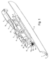
- the present invention comprises a seal 1, bonded to a metal insert 2, placed on to an eyelid body 3.
- the eyelid body is in turn pinned or otherwise attached to a rocker 4 and crank 5.
- the rocker is pinned or otherwise associated with a base 6.
- the crank is fixed to shaft extension 7.
- the shaft extension is located in the base by suitable means such as bushings 8, and connected to motor 9.
- the motor is attached to the base by motor mount plate 10.
- the assembly is preloaded by two torsion springs 11a and 11b, mounted at opposing ends of pins 12 fastening the rocker to the base.
- One end of the spring 11a is fixed in an aperture 13 in the base, while the opposing end bears on rocker/eyelid pin 14.
- Preloading the mechanism biases all pivot clearances in a predictable way. Additional sealing force is also obtained from the springs.
- the assembly forms a 4-bar linkage with the base as the ground.
- the crank is the driver
- the eyelid is the connecting link and the rocker the driven link. This allows a substantially horizontal motion while sealing against the catchplate and a vertical motion to give the operator access for service.
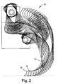
- the path 30 taken by the eyelid as it shifts from the sealed position 32 to the print position 34 to the service position 36 is shown in Fig. 2. As illustrated, the lower surface of the eyelid motion has minimal movement below the sealed position. Therefore the risk of the eyelid contacting the print media is minimized.
- the pivots for this four bar system are all located above the droplet generator, minimizing the risk of ink fouling up the mechanism.
- the base is mounted on the printhead frame and is accurately located by means of two alignment pins in the printhead frame engaging hole 20 and oval 21. Captive screws in holes 22 fasten the eyelid to the frame. By such locating features, the consistency of alignment of the eyelid to the catch plate is ensured, assuring consistent sealing of the printhead.
- the actuator of the eyelid with the four bar linkage is a stepper motor.
- the stepper motor provides a holding torque required to hold the eyelid in each functional position, while the mechanism is in use. It will be obvious to those skilled in the art that alternative motors or motor/encoder combinations could be used to perform the same function as the stepper in this embodiment.
- a desirable third position is a service position. This moves the eyelid much farther from the charge plate and orifice plate, allowing the operator to inspect these surfaces and perform manual cleaning steps as needed. Thus, it is no longer necessary to remove the eyelid to perform these functions.
- the stepper motor is a MicroMo Electronics (Clearwater, FL) AM1524 with a 159:1 planetary gear reducer.
- This stepper motor is preferred for its small size and large torque, 15 mm diameter and 42 oz-in respectively.
- Moving the eyelid from the sealed position to the print position involves stepping the motor through 45° of rotation.
- the actuation pulses to the stepper motor By controlling the actuation pulses to the stepper motor, the eyelid accelerations are controlled. The mechanical shocks produced by the solenoid actuations of the prior art are therefore eliminated.
- switch means 55 are attached to the eyelid body 3 are used to detect the eyelid in the closed and print positions. These switch means 55 are actuated by the fingers 54 of the actuator plate 53 which is attached to the base 6 when the eyelid is closed sufficiently. Multiple switch actuation positions are provided to determine eyelid closure and print position and to provide a high voltage interlock. One means to determining position is to have one switch open and another closed at the desired position. The motor controller can step open or closed as needed based on the switches status, thereby finding the proper opening.
- the switch actuating motion be between the eyelid base and the eyelid. This avoids backlash associated with the linkage. It does however, constrain the location of the switches as the eyelid motion may not be in an optimal direction for switch actuation or the desired switch position will interfere with the mechanism at some point in it's travel. It is desirable to minimize the eyelid size by keeping the switches near the center of the mechanism, yet still be able to adjust their actuating position.
- a compact means for adjustment of the switch operating position is effected by the position of the setscrews 52. These setscrews which are located in multiple tapped holes 51 in the base 6 bear on a flexible actuator plate 53, which is divided into fingers 54.
- switches of the switch means 55 can be actuated at multiple eyelid positions to detect eyelid closure and print position and to provide a high voltage interlock.
- these switches comprise Honeywell Microswitch UM40B switches, based on agency approval ratings and compact size.
- An additional switch 56 is mounted to the base to determine the service position. This switch is operated by contact with the rocker when the eyelid is opened to the service position. This switch requires no adjustment.
- the high voltage interlock switch is connected to the coil of a relay controlling the high voltage to the charge leads.
- the switch When the switch is not in contact with the actuation plate, the circuit is open, disabling the high voltage.
- the remaining switches provide logic signals to the print station of the eyelid position. Eyelid malfunction or removal is detectable by the print station, warning the operator and inhibiting certain operations.
- the multiple electrical devices are connected by a flexible circuit board for ease of assembly.
- the switches are soldered on prior to mechanical assembly, the motor connected while assembling the eyelid, and final electrical connection to the printhead made at installation.
- a flexible circuit heater 70 is attached to the inner surface of the eyelid, as shown in Fig. 4.
- the moisture from heated ink can saturate the air within the printhead with water vapor. This vapor then condenses on the cooler metal of the eyelid, leading to drops of water falling into the active area of the printhead. This may cause print disturbances or shorting of the charging electrodes. Heating the eyelid above the dew point keeps the condensate from forming.
- the voltage applied to the heater is varied in an open loop fashion, depending on the state of the printhead.
- One embodiment of the eyelid also comprises a spring metal seal along its upper edge. This reduces air leakage around the eyelid while the eyelid is in the print and sealed positions. This spring metal seal also serves as an EMI shield, helping to contain the electronic noise produced inside the printhead.
- the eyelid seal is a rubber strip, molded to a nickel plated aluminum strip. It is detachable from the main body of the eyelid, allowing replacement of the seal in the field should it become damaged.
- the eyelid seal could be a molded or extruded rubber seal which is slid into a retaining groove formed in the body of the eyelid.
- the rubber seal could be bonded to the eyelid body.
Landscapes
- Ink Jet (AREA)
Applications Claiming Priority (2)
| Application Number | Priority Date | Filing Date | Title |
|---|---|---|---|
| US211250 | 1998-12-14 | ||
| US09/211,250 US6247781B1 (en) | 1998-12-14 | 1998-12-14 | Ink jet printhead with an improved eyelid system |
Publications (3)
| Publication Number | Publication Date |
|---|---|
| EP1013439A2 true EP1013439A2 (fr) | 2000-06-28 |
| EP1013439A3 EP1013439A3 (fr) | 2000-11-08 |
| EP1013439B1 EP1013439B1 (fr) | 2006-08-30 |
Family
ID=22786134
Family Applications (1)
| Application Number | Title | Priority Date | Filing Date |
|---|---|---|---|
| EP99309552A Expired - Lifetime EP1013439B1 (fr) | 1998-12-14 | 1999-11-29 | Déflecteur d'encre pour tête d'impression à jet d'encre |
Country Status (5)
| Country | Link |
|---|---|
| US (1) | US6247781B1 (fr) |
| EP (1) | EP1013439B1 (fr) |
| JP (1) | JP2000218808A (fr) |
| CA (1) | CA2292097A1 (fr) |
| DE (1) | DE69932997T2 (fr) |
Cited By (4)
| Publication number | Priority date | Publication date | Assignee | Title |
|---|---|---|---|---|
| US6688736B1 (en) * | 2002-09-25 | 2004-02-10 | Scitex Digital Printing, Inc. | Wicking arrangement to eliminate catcher dripping |
| EP1403057A1 (fr) * | 2002-09-25 | 2004-03-31 | Scitex Digital Printing, Inc. | Paupière avec positionnement de maintenance actionné mécaniquement |
| EP1403058A1 (fr) * | 2002-09-25 | 2004-03-31 | Scitex Digital Printing, Inc. | Positionnement de paupière amélioré |
| EP1403060A1 (fr) * | 2002-09-25 | 2004-03-31 | Scitex Digital Printing, Inc. | Démarrage à rampe de pression rapide |
Families Citing this family (15)
| Publication number | Priority date | Publication date | Assignee | Title |
|---|---|---|---|---|
| US6935729B2 (en) | 2003-08-28 | 2005-08-30 | International Business Machines Corporation | Ink replenishment system and method for a continuous flow ink jet printer |
| FR2924379B1 (fr) * | 2007-11-29 | 2011-04-22 | Imaje Sa | Tete d'impression a jet d'encre a nettoyage automatise au demarrage d'impression |
| FR2937584B1 (fr) * | 2008-10-28 | 2010-12-24 | Imaje Sa | Imprimante a tete d'impresssion a jet continu et dispositif de nettoyage de la tete |
| US8128196B2 (en) * | 2008-12-12 | 2012-03-06 | Eastman Kodak Company | Thermal cleaning of individual jetting module nozzles |
| US7967423B2 (en) * | 2008-12-12 | 2011-06-28 | Eastman Kodak Company | Pressure modulation cleaning of jetting module nozzles |
| FR2955801B1 (fr) | 2010-02-01 | 2012-04-13 | Markem Imaje | Dispositif formant pupitre d'imprimante a jet d'encre continu, a concentrations de vapeur de solvant a l'interieur et autour du pupitre diminuees |
| EP2533979A1 (fr) * | 2010-02-13 | 2012-12-19 | Videojet Technologies, Inc. | Procédé de nettoyage d'imprimante |
| US9259916B1 (en) * | 2014-10-22 | 2016-02-16 | Eastman Kodak Company | Serviceable printhead sealing mechanism |
| US9527319B1 (en) | 2016-05-24 | 2016-12-27 | Eastman Kodak Company | Printhead assembly with removable jetting module |
| US9566798B1 (en) | 2016-05-24 | 2017-02-14 | Eastman Kodak Company | Inkjet printhead assembly with repositionable shutter |
| US9623689B1 (en) | 2016-05-24 | 2017-04-18 | Eastman Kodak Company | Modular printhead assembly with common center rail |
| US9789714B1 (en) | 2016-10-21 | 2017-10-17 | Eastman Kodak Company | Modular printhead assembly with tilted printheads |
| US9962943B1 (en) * | 2016-11-07 | 2018-05-08 | Eastman Kodak Company | Inkjet printhead assembly with compact repositionable shutter |
| US9969178B1 (en) * | 2016-11-07 | 2018-05-15 | Eastman Kodak Company | Inkjet printhead assembly with repositionable shutter mechanism |
| US10052868B1 (en) | 2017-05-09 | 2018-08-21 | Eastman Kodak Company | Modular printhead assembly with rail assembly having upstream and downstream rod segments |
Family Cites Families (11)
| Publication number | Priority date | Publication date | Assignee | Title |
|---|---|---|---|---|
| DE2430536C2 (de) * | 1974-06-26 | 1981-03-19 | M.A.N.- Roland Druckmaschinen AG, 6050 Offenbach | Einrichtung zur Sicherung von Schutzgittern bzw. Schutzabdeckungen an Druckmaschinen |
| US4160982A (en) * | 1978-03-24 | 1979-07-10 | A. B. Dick Company | Anti-dispersion accumulator for ink jet printing system |
| US4347520A (en) * | 1979-09-12 | 1982-08-31 | The Mead Corporation | Ink jet printer |
| US4573057A (en) * | 1985-03-04 | 1986-02-25 | Burlington Industries, Inc. | Continuous ink jet auxiliary droplet catcher and method |
| US4761665A (en) * | 1987-03-02 | 1988-08-02 | Eastman Kodak Company | High speed print/cartridge printer/feeder |
| US5475410A (en) * | 1992-03-19 | 1995-12-12 | Scitex Digital Printing, Inc. | Seal for ink jet printhead |
| US5475411A (en) * | 1992-05-29 | 1995-12-12 | Scitex Digital Printing, Inc. | Method of fabricating a catcher/charge plate assembly |
| JP3157987B2 (ja) * | 1994-07-28 | 2001-04-23 | シャープ株式会社 | インクジェット記録装置 |
| EP0805031B1 (fr) * | 1996-04-30 | 2000-01-19 | SCITEX DIGITAL PRINTING, Inc. | Moyens pour positionner un assemblage de paupière à une tête d'une imprimante à jet d'encre continu |
| DE69701920T2 (de) * | 1996-04-30 | 2000-12-07 | Scitex Digital Printing, Inc. | Lippenheizelement für kontinuierlich arbeitenden Tintenstrahldrucker |
| EP0813974B1 (fr) * | 1996-06-18 | 2003-03-12 | SCITEX DIGITAL PRINTING, Inc. | Tête d'impression par jet d'encre continu |
-
1998
- 1998-12-14 US US09/211,250 patent/US6247781B1/en not_active Expired - Lifetime
-
1999
- 1999-11-29 EP EP99309552A patent/EP1013439B1/fr not_active Expired - Lifetime
- 1999-11-29 DE DE69932997T patent/DE69932997T2/de not_active Expired - Lifetime
- 1999-12-13 JP JP11353035A patent/JP2000218808A/ja active Pending
- 1999-12-13 CA CA002292097A patent/CA2292097A1/fr not_active Abandoned
Non-Patent Citations (1)
| Title |
|---|
| None |
Cited By (4)
| Publication number | Priority date | Publication date | Assignee | Title |
|---|---|---|---|---|
| US6688736B1 (en) * | 2002-09-25 | 2004-02-10 | Scitex Digital Printing, Inc. | Wicking arrangement to eliminate catcher dripping |
| EP1403057A1 (fr) * | 2002-09-25 | 2004-03-31 | Scitex Digital Printing, Inc. | Paupière avec positionnement de maintenance actionné mécaniquement |
| EP1403058A1 (fr) * | 2002-09-25 | 2004-03-31 | Scitex Digital Printing, Inc. | Positionnement de paupière amélioré |
| EP1403060A1 (fr) * | 2002-09-25 | 2004-03-31 | Scitex Digital Printing, Inc. | Démarrage à rampe de pression rapide |
Also Published As
| Publication number | Publication date |
|---|---|
| DE69932997T2 (de) | 2007-05-10 |
| US6247781B1 (en) | 2001-06-19 |
| EP1013439B1 (fr) | 2006-08-30 |
| CA2292097A1 (fr) | 2000-06-14 |
| JP2000218808A (ja) | 2000-08-08 |
| EP1013439A3 (fr) | 2000-11-08 |
| DE69932997D1 (de) | 2006-10-12 |
Similar Documents
| Publication | Publication Date | Title |
|---|---|---|
| EP1013439B1 (fr) | Déflecteur d'encre pour tête d'impression à jet d'encre | |
| US5682186A (en) | Protective capping apparatus for an ink-jet pen | |
| US4112435A (en) | Protective and cleaning device for writing heads in ink recorder devices | |
| US6250735B1 (en) | Cover for print head alignment sensor | |
| US8226215B2 (en) | Jetting module install mechanism | |
| EP1238807B1 (fr) | Station d'entretien améliorée pour imprimante à jet d'encre | |
| US4500894A (en) | Device for covering and cleaning the discharge openings of ink printing heads | |
| US5627573A (en) | Maintenance device in an ink jet printing apparatus | |
| US20080204507A1 (en) | Fluid-ejection device service station | |
| US4668959A (en) | Mist reduction for ink jet printers | |
| US6910756B2 (en) | Eyelid with mechanically driven service position override | |
| EP1652675A1 (fr) | Procédé et appareil pour l'extraction d'aérosol dans des dispositifs d'éjection de liquide | |
| EP0720913B1 (fr) | Dispositif d'entretien dans un appareil d'impression à jet d'encre | |
| EP0818315B1 (fr) | Tête permettant un recouvrement pour imprimante à jet d'encre | |
| EP0585888B1 (fr) | Dispositif de détection de la position et de verrouillage du chariot "pour un appareil d'enregistrement" | |
| US20040061745A1 (en) | Fluid containment system including an ink redirection surface | |
| US10926541B2 (en) | Printing device | |
| US6042215A (en) | Capping device and printer including the same | |
| US9676196B1 (en) | Wiper system for cleaning inkjet printheads in inkjet printers | |
| US5343230A (en) | Electrical interconnect actuation which interacts with cap station articulation | |
| US5475410A (en) | Seal for ink jet printhead | |
| US20040252154A1 (en) | Maintenance station for an imaging apparatus | |
| US20080129055A1 (en) | Apparatus and method for holding a cover in a closed orientation | |
| EP1403058B1 (fr) | Positionnement de paupière amélioré | |
| EP3885145B1 (fr) | Appareil d'impression |
Legal Events
| Date | Code | Title | Description |
|---|---|---|---|
| PUAI | Public reference made under article 153(3) epc to a published international application that has entered the european phase |
Free format text: ORIGINAL CODE: 0009012 |
|
| AK | Designated contracting states |
Kind code of ref document: A2 Designated state(s): DE FR GB |
|
| AX | Request for extension of the european patent |
Free format text: AL;LT;LV;MK;RO;SI |
|
| PUAL | Search report despatched |
Free format text: ORIGINAL CODE: 0009013 |
|
| AK | Designated contracting states |
Kind code of ref document: A3 Designated state(s): AT BE CH CY DE DK ES FI FR GB GR IE IT LI LU MC NL PT SE |
|
| AX | Request for extension of the european patent |
Free format text: AL;LT;LV;MK;RO;SI |
|
| RIC1 | Information provided on ipc code assigned before grant |
Free format text: 7B 41J 29/02 A |
|
| 17P | Request for examination filed |
Effective date: 20010426 |
|
| AKX | Designation fees paid |
Free format text: DE FR GB |
|
| RAP1 | Party data changed (applicant data changed or rights of an application transferred) |
Owner name: EASTMAN KODAK COMPANY |
|
| 17Q | First examination report despatched |
Effective date: 20040816 |
|
| GRAP | Despatch of communication of intention to grant a patent |
Free format text: ORIGINAL CODE: EPIDOSNIGR1 |
|
| GRAS | Grant fee paid |
Free format text: ORIGINAL CODE: EPIDOSNIGR3 |
|
| GRAA | (expected) grant |
Free format text: ORIGINAL CODE: 0009210 |
|
| AK | Designated contracting states |
Kind code of ref document: B1 Designated state(s): DE FR GB |
|
| REG | Reference to a national code |
Ref country code: GB Ref legal event code: FG4D |
|
| REF | Corresponds to: |
Ref document number: 69932997 Country of ref document: DE Date of ref document: 20061012 Kind code of ref document: P |
|
| ET | Fr: translation filed | ||
| PLBE | No opposition filed within time limit |
Free format text: ORIGINAL CODE: 0009261 |
|
| STAA | Information on the status of an ep patent application or granted ep patent |
Free format text: STATUS: NO OPPOSITION FILED WITHIN TIME LIMIT |
|
| 26N | No opposition filed |
Effective date: 20070531 |
|
| PGFP | Annual fee paid to national office [announced via postgrant information from national office to epo] |
Ref country code: DE Payment date: 20121130 Year of fee payment: 14 Ref country code: FR Payment date: 20121113 Year of fee payment: 14 |
|
| PGFP | Annual fee paid to national office [announced via postgrant information from national office to epo] |
Ref country code: GB Payment date: 20121025 Year of fee payment: 14 |
|
| GBPC | Gb: european patent ceased through non-payment of renewal fee |
Effective date: 20131129 |
|
| REG | Reference to a national code |
Ref country code: FR Ref legal event code: ST Effective date: 20140731 |
|
| REG | Reference to a national code |
Ref country code: DE Ref legal event code: R119 Ref document number: 69932997 Country of ref document: DE Effective date: 20140603 |
|
| PG25 | Lapsed in a contracting state [announced via postgrant information from national office to epo] |
Ref country code: DE Free format text: LAPSE BECAUSE OF NON-PAYMENT OF DUE FEES Effective date: 20140603 |
|
| PG25 | Lapsed in a contracting state [announced via postgrant information from national office to epo] |
Ref country code: GB Free format text: LAPSE BECAUSE OF NON-PAYMENT OF DUE FEES Effective date: 20131129 Ref country code: FR Free format text: LAPSE BECAUSE OF NON-PAYMENT OF DUE FEES Effective date: 20131202 |