EP1013140B1 - 5-2-5 matrix dekodierungssystem - Google Patents
5-2-5 matrix dekodierungssystem Download PDFInfo
- Publication number
- EP1013140B1 EP1013140B1 EP98945881A EP98945881A EP1013140B1 EP 1013140 B1 EP1013140 B1 EP 1013140B1 EP 98945881 A EP98945881 A EP 98945881A EP 98945881 A EP98945881 A EP 98945881A EP 1013140 B1 EP1013140 B1 EP 1013140B1
- Authority
- EP
- European Patent Office
- Prior art keywords
- center
- surround
- decoder
- signal
- steering
- Prior art date
- Legal status (The legal status is an assumption and is not a legal conclusion. Google has not performed a legal analysis and makes no representation as to the accuracy of the status listed.)
- Expired - Lifetime
Links
Images


Classifications
-
- H—ELECTRICITY
- H04—ELECTRIC COMMUNICATION TECHNIQUE
- H04S—STEREOPHONIC SYSTEMS
- H04S3/00—Systems employing more than two channels, e.g. quadraphonic
- H04S3/02—Systems employing more than two channels, e.g. quadraphonic of the matrix type, i.e. in which input signals are combined algebraically, e.g. after having been phase shifted with respect to each other
Definitions
- This invention relates to sound reproduction systems involving the decoding of a stereophonic pair of input audio signals into a multiplicity of output signals for reproduction after suitable amplification through a like plurality of loudspeakers arranged to surround a listener.
- the present invention concerns an improved set of design criteria and their solution to create a decoding matrix having optimum psychoacoustic performance in reproducing encoded multichannel material as well as standard two channel material, that includes maintaining high separation between left and right components of stereo signals under all conditions, even when there is a net forward or rearward bias to the input signals, or when there is a strong sound component in a particular direction, while maintaining high separation between the various outputs for signals with a defined direction, and while maintaining non-directionally encoded components at a constant acoustic level regardless of the direction of directionally encoded components of the input audio signals, including frequency dependent circuitry that improves the balance between front and rear signals, provides smooth sound motion around a seven channel version of the system, and makes the sound of a five channel version closer to that of a seven channel version.
- the present invention is part of a continuing effort to refine means for separating two channels into the multichannel signals from which they were derived.
- One of the goals of this decode process is to recreate the original signals as perceptually identical to the originals as possible.
- Another important goal of the decoder is to extract five or more separate channels from a two channel source that was not encoded from a five channel original. The resulting five channel presentation must be at least as musically tasteful and enjoyable as the original two channel presentation.
- the present invention is concerned with improvements to the derivation of suitable variable matrix coefficients.
- this disclosure makes reference to Griesinger's U.S. Patent No. 4,862,502 (1989 ) which will be referred to as the '89 patent: U.S. Patent No. 5,136,650 (1992 ), which will be referred to as the '92 patent; the July 1996 Griesinger U.S. Patent Application No. 08/684,948 referenced as the July '96 application; and the November 1996 Griesinger U.S. Patent Application No. 08/742,460 , referred to as the November '96 application.
- Commercial versions of the decoder based upon this last application will be referred to as Version 1.11 (or V1.11).
- the present invention is concerned with the realization of an active matrix having certain properties that maximize its psychoacoustic performance. In another aspect it discloses frequency dependent modification of certain of the outputs from the active matrix.
- the present invention is defined in claim 1.
- the invention is in part an active matrix decoder having matrix elements that vary depending on the directional component of the incoming signals.
- the matrix elements vary in such a way as to reduce the loudness of directionally encoded signals in outputs that are not involved in the intended direction, while enhancing the loudness of these signals in directions that are involved in reproducing the intended direction, while preserving at all times the left/right separation of other signals that may be present at the same time at the inputs.
- matrix elements in accordance with the invention restore the left/right separation of decorrelated two channel material that has been directionally encoded by increasing or decreasing the blend between the two inputs - for example with a stereo width control.
- matrix elements in accordance with the invention are designed to preserve as much as possible the energy balance between various components of the input signal, such that the balance between vocals and accompaniment is preserved in the decoder outputs.
- matrix elements in accordance with the invention preserve both the loudness of non directionally encoded elements of the input sound and the left/right separation of these elements.
- decoders in accordance with preferred embodiments of the invention include frequency dependent circuits that improve the compatibility of the decoder outputs when standard two channel material is played, that convert the surround outputs from two for a five channel decoder to four for a seven channel decoder, and that modify the spectrum of the rear channels in a five channel decoder so that the sound direction appears to be more like the sound direction from a seven channel decoder.
- the decoder in this application will be described as consisting of two separate parts.
- the first part is a matrix that splits the two input channels into five output channels, which are usually identified as center, left front, right front, left rear and right rear.
- the second part consists of a series of delays and filters that modify the spectrum and the levels of the two rear outputs.
- One of the functions of the second part is to derive an additional pair of outputs, left side and right side, when a seven channel version of the decoder is desired.
- the second part was not explicit - the two additional channels were derived from an additional pair of matrix elements in the original matrix.
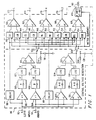
- FIG. 1 which is identical to FIG. 4 in U. S. Patent Application No. 08/742,460 , shows a block diagram of the first part of the decoder, a two channel to five channel matrix 90.
- the left half of FIG. 1 partitioned by a vertical dashed line shows a means for deriving the two steering voltages l / r and c / s. These voltages represent the degree to which the input signals have an inherent or encoded directional component in the left/right or front/back directions respectively.
- This part of the FIG. will not be explicitly discussed in this application as it has been fully described in the above patent application.
- the directional detection means of decoder 90 comprising elements 92 through 138 -is followed by a 5 x 2 matrix to the right of the vertical dashed line.
- the elements of this matrix 140 through 158 determine the amount of each input channel that is linearly combined with the other input channel to form each output channel.
- These matrix elements are assumed to be real. (The case of complex matrix elements was described in U. S. Patent Application No. 08/742,460 and will not be discussed here.)
- the matrix elements are functions of the two steering voltages l / r and c / s.
- U. S. PatentApplication No. 08/742,460 presented mathematical formulae for these functions. Part of the novelty in this application lies in improvements to these formulae. We present these formulae graphically and give an explanation for why they take the shape they do.
- the steering voltages c / s and l / r are derived from the logarithm of the ratio of the left input amplitude at terminal 92 to the right input amplitude at terminal 94, and the logarithm of the ratio of the sum amplitude to the difference amplitude.
- l / r and c/s as angles that vary from +45 degrees to --45 degrees.
- these voltages have the units of decibels.
- the angles lr and cs determine the degree to which the input signals have a directional component. For example, when the inputs to the decoder are decorrelated, both lr and cs are zero. For a signal that comes from the center only, lr is zero, and cs has the value 45 degrees. For a signal that comes from the rear, lr is zero, and cs is -45 degrees. Similarly, a signal that comes from the left has an lr value of 45 degrees and a cs value of zero, and a signal from the right has an lr value of -45 degrees, and a cs value of zero.
- the matrix elements shown in FIG. 1 are real and thus frequency independent. All signals in the inputs will be directed to the outputs depending on the derived angles lr and cs. (In the current art low frequencies and very high frequencies are attenuated in the derivation of lr and cs from the input signals by filters not shown in FIG. 1 . However, the matrix itself is broadband.)
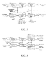
- FIG. 2 shows a five channel version of the additional frequency dependent circuits. These circuits do not have fixed parameters. The frequency and level behavior is dependent on the steering values lr and cs. The circuits accomplish several purposes. First, in both a five channel and a seven channel decoder, the additional elements allow the apparent loudness of the rear channels to be adjusted when the steering is neutral (lr and cs 0) or toward the front ( cs > 0). In U. S. Patent Application No. 08/742,460 this attenuation was performed as part of the matrix itself. and was frequency independent. We have found with theoretical studies and listening tests that it is highly desirable for the low frequencies to be reproduced from the sides of the listener. Thus in the decoder presented here only the high frequencies are attenuated by variable low pass filters 182, 184, 188, and 190.
- Further elements 192, 194 in the five channel version modify the spectrum of the sound when the steering is toward the rear ( cs ⁇ 0) using the c / s signal 196 such that the loudspeakers seem to be located behind the listener, even if their actual position is to the side.
- the modified left surround and right surround signals appear at terminals 198 and 200, respectively. Additional details of this circuit will be given in a later section of this disclosure.
- FIG. 3 shows the seven channel version of the frequency dependent elements.
- the first set of filters 182, 184, 188, 190 attenuate the upper frequencies of the side and rear outputs when the steering is neutral or forward, again controlled by the background control signal 186. This attenuation also results in a more forward sound image, and can be adjusted to the listener's taste.
- additional circuits 202, 204, 206, 208 act to differentiate the side outputs from the rear outputs. As steering moves rearward the attenuation mentioned above in the side speakers is first removed by elements 204 and 206 to produce a side oriented sound.
- FIG. 4 shows a block diagram of an encoder according to an example, which is useful for understanding the invention.
- the encoder is designed to automatically mix five input channels into two output channels.
- the architecture is quite different from the encoder described in U. S. Patent Application No. 08/742,460 .
- the object of the new design is to preserve the musical balances of the five channel original, while providing phase/amplitude cues that allow the original five channels to be extracted by the decoder.
- the previous encoder had similar goals, but there have been improvements in the methods used to achieve these goals.
- the preservation of musical balances is highly important in the encoder.
- One of the primary purposes of the encoder is to automatically create a two channel mix of a five channel recording, that will play in an ordinary two channel system with the same artistic quality as the five channel original.
- the new encoder design includes active elements to ensure that musical balance is preserved.
- the new design allows input signals to be panned between any of the five inputs of the encoder. For example, a sound may be panned from the left front input to the right rear input.
- the resulting two channel signal is decoded by the decoder described in this application the result will be quite close to the original sound. Decoding through an earlier surround decoder will also be similar to the original.
- the most basic goals of the current invention are identical to the goals of our previous decoders, particularly the one described in U. S. Patent Application No. 08/742,460 - "The invention is a surround sound decoder having variable matrix values so constructed as to reduce directionally encoded audio components in outputs which are not directly involved in reproducing them in the intended direction; enhance directionally encoded audio components in the outputs which are directly involved in reproducing them in the intended direction so as to maintain constant total power for such signals; while preserving high separation between the left and right channel components of non-directional signals regardless of the steering signals; and maintaining the loudness defined as the total audio power level of non-directional signals effectively constant whether or not directionally encoded signals are present and regardless of their intended direction if present.”
- the front input signals L, C and R are applied to input terminals 50, 52 and 54 respectively.
- L and R go directly to the adders 278 and 282 respectively, while the C signal is first attenuated by a factor fcn in attenuator 372 before being applied to inputs of both adders 2 78 and 282.
- the low frequency effects signal LFE is passed through a gain of 2.0 in element 374 and then applied to both adders 278 and 282.
- the surround input signals LS and RS are applied through two input terminals 62 and 64 respectively each to two separate paths: for the LS signal, the path through attenuator 378 has gain fs(l,ls) and the RS signal passes through a corresponding attenuator 380 with gain fs(r,rs).
- the outputs of these are passed into cross-coupling elements 384 and 386 having a gain factor of - crx , where crx is nominally 0.383.
- the cross-coupled signals from these elements are fed to summers 392 and 394 which also receive the attenuated LS and RS signals from 0.91 attenuators 388 and 392.
- the outputs of summers 392, 394 are applied to inputs of the adders 278, 282. This positions the elements respectively at 45 degrees left and right of center rear in the decoded space.
- the other signal branch passes the LS and RS signals through attenuators 376 with gain fc(l,ls) and 382 with gain fc ( r,rs ) respectively, and then through a similar arrangement of cross-coupling elements 396, 398, 402, 404, 406, and 408, the summers 406 and 408 having outputs representing left rear and right rear inputs at 45 degrees left and right of center rear, as before.
- these signals now each pass through phase shifter elements 234 and 246 respectively, while the left and right signals from adders 278 and 282 pass through phase shifter elements 286 and 288 respectively.
- phase shifter elements is an all-pass filter, the phase response being ⁇ ( f ) for elements 286 and 288, and ⁇ ( f )-90° for elements 234 and 246. Calculation of the component values required in these filters is well known in the art, and will not be discussed further here. The result is that the outputs of summers 406 and 408 are caused to lag those of adders 278 and 282 by 90 degrees at all frequencies after passage through the all-pass filter networks as shown in FIG. 4 .
- the gain functions fs and fc are designed to allow strong surround signals to be presented in phase with the other sounds while weak surround signals pass through the 90 degree phase-shifted path to retain constant power for decorrelated "music" signals.
- the value of crx can also change, and varies the angle from which the surround signals are heard.
- both the left decoder Input and the right decoder input will be reproduced by the center speaker, and sounds that were originally only in the left (or right) channel will also be reproduced from the center.
- the result must be that the apparent positions of these sounds will be drawn to the middle of the room. The degree to which this occurs depends on the loudness of the center channel.
- U. S. Patents Nos. 4,862,502 and 5,136,650 used matrix elements that had a minimum value of 3dB compared to the left and right channels. When the inputs to the decoder were decorrelated the loudness of the center channel was equal to the loudness of the left and right channels. As steering moved forward the center matrix elements increased another 3dB. The effect of this high loudness is to strongly reduce the width of the front image. Instruments that should have sounded at the left and the right of the sound image are always drawn toward the center of the sound image.
- U. S. Patent Application No. 08/742,460 used center matrix elements that had a minimum value 4.5dB less than the earlier values. This minimum value was chosen on the basis of listening tests. This attenuation causes a pleasing spread to the front image when the input material is uncorrelated - as with orchestral music. The front image is not seriously narrowed. In U. S Patent Application No. 08/742,460 as the steering moved forward these matrix elements increased, ultimately reaching the values used in the Dolby matrix.
- the decoder of V1.11 used the matrix elements of U. S. Patent No. 4,862,502 for the front channels under these conditions. These matrix elements do not fully eliminate a rear steered signal unless it was steered to the full rear position - half way between left rear and right rear. When steering was to left rear or right rear (not full rear) the left or right front output had an output 9dB less than the corresponding rear output.
- the front matrix elements are modified to eliminate sound from the front when steering is anywhere between left rear and right rear.
- the improvements to the rear matrix elements are not immediately obvious to a typical listener. These improvements correct various errors in the continuity of the matrix elements across the boundaries between quadrants. They also improve the power balance between steered signals and unsteered signals under various conditions. The mathematical description of the matrix elements that will be given later includes these improvements.
- Matlab The math used to describe the matrix elements is not based on continuous functions of the variables cs and lr. In general there are conditionals, absolute values, and other non-linear modifications to the formulae. For this reason we will describe the matrix elements using a programming language.
- phase/amplitude decoders determine the apparent direction of the input by comparing the ratio of the amplitudes of the input signals. For example, the degree of steering in the right/left direction is determined from the ratio of the left input channel amplitude to the right input channel amplitude. In a similar way, the degree of steering in the front/back direction is determined from the ratio of the amplitudes of the sum and the difference of the input channels.
- Logic 7 decoders differ from standard decoders significantly in how this is done. We assume that the steering directions have been determined.
- the two steering directions have their maximum value. However under these conditions they are not independent.
- the advantage to representing the steering values as angles is that when there is only a single signal the absolute value of the two steering values must sum to 45 degrees.
- the input includes some decorrelated material along with a strongly steered signal, the sum of the absolute values of the steering values must be less than 45 degrees. lr + cs ⁇ 45 If we plot the values of the matrix elements over a two-dimensional plane formed by the steering values, the center of the plane will have the value (0, 0) and the legal values for the sum of the steering values will not exceed 45 .
- the elements presented here are not always correctly scaled. In general they are presented so that the unsteered value of the of the non-zero matrix elements are for any given channel is one. In practice the elements are usually scaled so the maximum value of each element is one or less. In any case, in a final product the scaling of the elements is additionally varied in the calibration procedure.
- the matrix elements presented here should be assumed to be scalable by appropriate constants.
- cs and lr are the steering directions in degrees in the center/surround and left/right axis respectively.
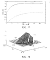
- G( x ) was determined experimentally in the 1989 patent, and is specified mathematically in the '91 patent. It varies from 0 to 1 as x varies from 0 to 45 degrees.
- G( x ) can be shown to be equal to 1-
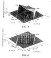
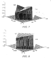
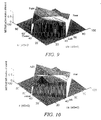
- G( x ) can also be described in terms of the steering angles using various formulae. One of these is given in the '91 patent, and another will be given later in this document. See FIG. 5 and FIG. 6 for graphical representations of the LFL and LFR matrix elements plotted three-dimensionally against the lr and cs axes.
- FIG. 7 shows the sum of the squares of these elements, demonstrating that the above matrix elements do not meet the requirement of constant loudness.
- the value is constant at .71 along the axis from unsteered to right.
- the unsteered to left rises 3dB to the value one, and the unsteered to center or to rear falls by 3dB to the value 0.5.
- This part of the graph is hidden by the peak at left.
- the rear direction level is identical to that at the center direction.
- G(x) 1 - tan 45 - x
- boost 1 (cs) as used in March 1997 was a linear boost of 3dB total applied over the first 22.5 degrees of steering, decreasing back to 0dB in the next 22.5 degrees.
- Boost( cs ) is given by corr( x ) in the Matlab code below (comment lines are preceded by the percent symbol %).
- the performance of the March 1997 circuit can be improved.
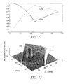
- the first problem is in the behavior of the steering along the boundaries between left and center, and between right and center. As a strong single signal pans from the left to the center, it can be seen in FIG. 9 that the value of the LFL matrix element increases to a maximum half-way between left and center. This increase in value is an unintended consequence of the deliberate increase in level for the left and right main outputs as a center signal is added to stereo music.
- LFL and LFR in the front right quadrant are similar, but without the +0.41*G term. These new definitions lead to the matrix element shown graphically in FIG. 10 .
- LFL cos t * F t - / + sin t * sqrt ⁇ 1 - F ⁇ t ⁇ ⁇ 2
- LFR ( sin t * cos 4 * t - cos t * sin 4 * t
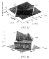
- FIG 12 which views the coefficient graph from left rear, note the large correction along the left-rear boundary. This causes the front left output to go to zero when steering goes from left to left rear. The output remains zero as the steering progresses to full rear.
- the function is identical to the Dolby matrix.
- the unsteered (middle) to right axis has the value one
- the center vertex has the value 0.71
- the rear vertex has the value 0.5
- the left vertex has the value 1.41. Note the peak along the middle to center axis.
- the Dolby elements are similar to our '89 patent elements, but without the boost dependent on cs in the rear. This difference is in fact quite important, as after the standard calibration procedure the elements have quite different values for unsteered signals.
- our description of the matrix elements does not consider the calibration procedure for these decoders. We derive all the matrix elements with a relatively arbitrary scaling. In most cases the elements are presented as if they had a maximum value of 1.41. In fact, for technical reasons the matrix elements are all eventually scaled so they have a maximum value of less than one. In addition, when the decoder is finally put to use, the gain of each output to the loudspeaker is adjusted.
- the 3dB difference in the elements in the forward steered or unsteered condition is not trivial.
- the elements from the '89 patent have the value 0.71, and the sum of the squares of the elements has the value of one. This is not true of the Dolby rear elements when calibrated.
- LRL has the unsteered value of one, and the sum of the squares is 2, or 3dB higher than the '89 outputs.
- the calibration procedure results in a matrix that does not correspond to a "Dolby Surround" passive matrix when the matrix is unsteered.
- the Dolby Surround passive matrix specifies that the rear output should have the value of .71*(A in - B in ), and the Pro-Logic matrix does not meet this specification.
- the sound power in the room will be proportional to L in 2 + R in 2 + C in 2 . If all three components have roughly equal amplitudes, the power ratio of the center component to the left plus right component will be 1:2.
- the major problem with both the '89 elements and the Dolby elements is that there is only a single rear output.
- the '91 patent disclosed a method for creating two independent side outputs, and the math in that patent was incorporated in the front left quadrant in reference [1] of 1996 and the application No. 08/742,460 .
- the goal of the elements in this quadrant was to eliminate the output of a signal steered from left to center, while maintaining some output from the left rear channel for unsteered material present at the same time.
- the LRL matrix element would have the following form:
- these matrix elements are very similar to the '89 elements, but with the addition of a G(lr) term in LRR, and a GS term in LRL.
- G( lr ) was included to add signals from the B input channel of the decoder to the left rear output, to provide some unsteered signal power as the steered signal was being removed.
- GS(lr) the criterion, that there should be no signal output with a fully steered signal moving from left to center.
- the formula for GS(lr) turned out to be equal to G 2 (lr), although a more complicated representation of the formula is given in the '91 patent. The two representations can be shown to be identical.
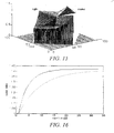
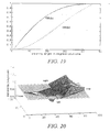
- FIG. 18 shows several problems with the sound power.
- This dip exists because of the functional shape of G( lr ) in LRR is not optimal.
- the choice of G( lr ) was arbitrary - in the earlier design this function already existed in the decoder, and its implementation in analog circuitry is easy.
- FIG. 20 in this application shows the matrix elements without the "tv matrix” correction. In this application this correction is handled by the frequency dependent circuitry that follows the matrix and will be described later.
- the interpolation causes the value to match the value of GS( lr ) when cs is zero, and allows the value to rise smoothly to the value given by the previous math as cs increases negatively toward the rear.
- the steered component of the input should be removed from the left outputs - there should be no output from the rear left channel when the steering is toward the right or right rear.
- the matrix elements given in the '91 patent achieve this goal. They are essentially the same as the rear matrix elements in the 4 channel decoder, with the addition of the sin( cs )+ cos( cs ) correction for the unsteered loudness.
- Rboost(cs) is defined in reference [1] and application No. 08/742,460 . It is closely equivalent to the function 0.41*G(cs) in the earlier matrix elements, except that rboost( cs ) is zero for 0 > cs > -22.5, and varies from zero to 0.41 as cs varies from -22.5 degrees to -45 degrees. Its exact functional shape is determined by the desire to keep the loudness of the rear output constant as sound is panned from left rear to full rear.
- the behavior of the Left Rear Left and Left Rear Right elements is much more complex.
- the Left Rear Left element must quickly rise from zero to near maximum as lr decreases from 4.5 to 22.5, or to zero.
- LRL is computed with interpolation, just as for LRR.
- Matlab notation In Matlab notation:
- the middle of the graph, and the right and rear vertices have the value 1.
- the center vertex has the value 1.41. In practice this element is scaled so the maximum value is one.
- the boost function of cs starts at zero as before, and rises with cs in such a way that CL and CR increase 4.5dB as cs goes from zero to 22.5 degrees.
- the increase is a constant number of dB for each dB of increase in cs.
- the boost function then changes slope, such that in the next 20 degrees the matrix elements rise another 3dB, and then hold constant.
- the new matrix elements are equal to the neutral values of the old matrix elements.
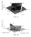
- the output of the center channel is thus 4.5dB less than the old output when steering in neutral, but rises to the old value when the steering is fully to the center. See FIG. 22 for a plot in three dimensions of this element.
- FIG. 23 shows the center gain needed (solid curve) if the energy of the center component of the input signal is to be preserved in the front three channels as steering increases toward the front.
- the needed rise in the level of the center channel is quite steep - the rise is many dB of amplitude per dB of steering value.
- the gain in a standard decoder (dotted curve).
- the function (0.42 + GC( cs )) is plotted in FIG. 2 . 5 . Note the quick rise from the value 0.42 (45dB lower than Dolby surround), followed by a gentle rise, followed finally by a steep rise to the value 1..
- LFL GP cs
- RATIO C in 2 / L in 2 * 0.5
- the solid curve is the graph of GF needed for constant energy ratios with the new "music" center attenuation GC.
- the dashed curve is the LFR element of March '97, sin( cs )*corr1.
- the dotted curve is sin(cs), the LFR element without the correction term corr1. Note that GF is close to zero until cs reaches 30 degrees, and then increases sharply. We have found in practice it is best to limit the value of cs at about 33 degrees. In practice LFR derived from these curves has a negative sign.
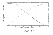
- FIG 29 which is a graph of the left front (dotted curve) and center (solid curve) outputs, note that center steering is at the left of the plot, and full left is at the right.
- cs the value of cs to about 33 degrees, (about 13 on the axis as labeled) where the center is about 6dB stronger than the left.
- the Logic 7 encoder There are two major goals of the Logic 7 encoder. Firstly, it should be able to encode a 5.1 channel tape in a way that allows the encoded version to be decoded by a Logic 71 decoder with minimal subjective change. Secondly, the encoded output should be stereo compatible - that is, it should sound as close as possible to a manual two channel mix of the same material. One factor in this stereo compatibility should be that the output of the encoder, when played on a standard stereo system, should give identical perceived loudness for each sound source in an original 5 channel mix. The apparent position of the sound source in stereo should also be as close as possible to the apparent position in the 5 channel original.
- the new encoder handles the left, center, and right signals identically to the previous design and identically to the Dolby encoder, providing the center attenuation function fcn is equal to 0.71, or -3dB.
- the surround channels look more complicated than they are.
- the functions fc () and fs () direct the surround channels either to a path with a 90 degree phase shift relative to the front channels, or to a path with no phase shift.
- fc In the basic operation of the encoder fc is one, and fs is zero - that is, only the path which uses the 90 degree phase shifts is active.
- the value crx is typically 0.38. It controls the amount of negative cross feed for each surround channel. As in the previous encoder, when there is only an input to one of the surround channels the A and B outputs have an amplitude ratio of -.38/.91, which results in a steering angle of 22.5 degrees to the rear. As usual, the total power in the two output channels is unity - that is the sum of the squares of .91 and .38 is one.
- a major function of the function fc in the surround channels is to reduce the level of the surround channels in the output mix by 3dB when the surround channels are much softer than the front channels. Circuitry is provided to compare the front and rear levels, and when the rear is less by 3dB, the value of fc is reduced to a maximum of 3dB. The maximum attenuation is reached when the rear channels are 8dB less strong than the front channels.
- This active circuit appears to work well. It makes the new encoder compatible with the European standard encoder for classical music. The action of the active circuits causes instruments which are intended to be strong in the rear channels to be encoded with full level.
- Level detecting circuits look at the phase relationship between the center channel and the front left and right. Some popular music recordings that use five channels mix the vocals into all three front channels. When there is a strong signal in all three inputs the encoder output will have excessive vocal power, since the three front channels will add together in phase. When this occurs, active circuits increase the attenuation in the center channel by 3dB to restore the power balance in the encoder output.
- FIG. 2 shows a block diagram of the frequency dependent circuits that follow the matrix in a five channel version of the decoder.
- the HRTF filter changes its characteristics depending on the value of the rear steering voltage c/s.
- the first two filters change their characteristics in response to a signal that is intended to represent the average direction of the input signals to the decoder during pauses between strongly steered signals. This signal is called the background control signal.
- One of the major goals of the current decoder is to be able to optimally create a five channel surround signal from an ordinary two channel stereo signal. It is also highly desirable that the decoder should recreate a five channel surround recording that was encoded into two channels by the encoder described as part of this application. These two applications differ in the way the surround channels are perceived. With an ordinary stereo input the majority of the sound needs to be in front of the listener. The surround speakers should contribute a pleasant sense of envelopment and ambience, but should not draw attention to themselves. An encoded surround recording needs the surround speakers to be stronger and more aggressive.
- the background control signal is designed to make this discrimination.
- the background control signal (BCS) is similar to and derived from the rear steering signal cs.
- BCS represents the negative peak value of cs. That is, when cs more negative than BCS, then BCS is made to equal cs. When cs is more positive than BCS the value of BCS slowly decays. However the decay of BCS involves a further calculation.
- Music of many types consists of a series of strong foreground notes - or in the case of a song, sung words. In between the foreground notes there is a background.
- the background may consist of other instruments playing other notes, or it may consist of reverberation.
- the circuit that derives the, BCS signal keeps track of the peak level of the foreground notes. When the current level is -7dB less than the peak level of the foreground, the level of cs is measured. The value of cs during these gaps between foreground peaks is used to control the decay of BCS. If the material in the gaps between notes is reverberation, it may tend to have a net rearward bias in a recording that was made by encoding a five channel original. This is because the reverberation on the rear channels of the original will be encoded with a rearward bias. The reverberation in an ordinary two channel recording will have no net rearward bias. Cs for this reverberation will be zero or slightly forward.
- BCS derived in this way tends to reflect the type of recording. Any time there is significant rear steered material BCS will always be strongly negative. However BCS can be negative even in the absence of strong steering to the rear if there the reverberation in the recording has a net rearward bias. We can use BCS to adjust the filters that optimize the decoder for stereo vs surround inputs.
- the first of the filters in FIG. 2 is a simple 6dB per octave low pass filter, with an adjustable cutoff frequency.
- this filter When BCS is positive or zero this filter is set to a value that is user adjustable, but is typically about 4kHz. As BCS becomes negative the cutoff frequency is raised, until when BCS is more rearward than 22 degrees the filter is not active. This low frequency filter makes the rear outputs less obtrusive when ordinary stereo material is played.
- the filter has been a part of the decoder at least since V1.11, but in the earlier decoders it was controlled by cs , and not by BCS.
- the second filter is a variable shelf filter.
- the low frequency section (the pole) of this filter is fixed, at 500 Hz.
- the high frequency section (the zero) varies depending on user adjustment and on BCS.
- This filter implements the "soundstage" control in the current decoder.
- "soundstage" is implemented through the matrix elements, using the "tv matrix” correction.
- the earlier decoders based on this work reduced the overall level of the rear channels when the steering was neutral or forward. In the new decoder presented here the matrix elements do not include the "tv matrix” correction.
- the high frequency section of the shelf filter is set equal to the low frequency section - in other words the shelf has no attenuation. and the filter has flat response.
- the third filter is controlled by c / s and not by BCS.
- This filter is designed to emulate the frequency responses of the human head and pinnae when a sound source is approximately 150 degrees in azimuth from the front of the listener.
- This type of frequency response curve is called a "Head Related Transfer Function" or HRTF.
- HRTF Head Related Transfer Function
- the current standard for five channel sound reproduction recommends that the two rear speakers be placed slightly behind the listener, at +/-110 or 120 degrees from the front. This speaker position supplies good envelopment at low frequencies.
- a sound from the side a listener does not produce the same level of excitement as a sound that is fully behind a listener.
- a listening room does not have a size or shape that is appropriate to place the loudspeakers fully behind the listener, and a side position is the best that can be achieved.
- the HRTF filter in the decoder adds the frequency notches of a rear sound source, so that a listener hears the sound as further behind that the actual position of the loudspeaker.
- the filter is designed to vary with cs. When cs is positive or zero, the filter is maximum. This causes ambient sounds and reverberation to seem to be more behind the listener. As cs becomes negative the filter is reduced. When cs is approximately -15 degrees the filter is completely removed, and the sound source appears to come fully from the side. As cs goes further negative the filter is once again applied, so the sound source appears to go behind the listener. When cs is fully to the rear the filter is slightly modified to correspond to the HRTF function for a sound fully to the rear.
- FIG. 3 shows the frequency dependent circuits the seven channel version of the decoder. These are shown as consisting of three sections - although in an actual implementation the second two sections can be combined into one circuit.
- the first two sections are identical to the two sections in the five channel decoder, and perform the same function.
- the third section is unique to the seven channel decoder.
- the side and the rear channels had separate matrix elements. The action of the elements was such that when cs was positive or neutral the side and the rear outputs were identical except for delay. The two outputs stayed identical until cs was more negative than 22 degrees. As the steering moved further to the rear the side outputs were attenuated by 6dB, and the rear outputs were boosted by 2dB. This caused the sound to appear to move from the sides of the listener to the rear of the listener.
- the differentiation between the side output and the rear output is achieved by a variable shelf filter in the side output.
- the third shelf filter in FIG. 3 has no attenuation when cs is forward or zero. When cs becomes more negative than 22 degrees the zero in the shelf filter moves rapidly toward 1100Hz, resulting in an attenuation of the high frequencies of about 7dB.
- this shelf filter has been described as a separate filter from the shelf filter that provides the "soundstage" function, the action of the two shelf filters can be combined into a single shelf through suitable control circuitry.
Claims (14)
- Raumklang-Decoder (90) zum Umverteilen eines Paars linker und rechter Audioeingangssignale, die richtungsabhängig codierte und richtungsunabhängige Komponenten umfassen, auf eine Mehrzahl von Ausgangskanälen (172, 174, 176, 178, 180) zur Wiedergabe über Lautsprecher, die einen Hörbereich umgeben, und umfassend Mittel zum Bestimmen des richtungsabhängigen Gehalts der linken und rechten Audiosignale und zum Erzeugen daraus mindestens eines linken/rechten Lenksignals und eines mittleren/Raumklang-Lenksignals, wobei der Decoder Folgendes umfasst:linke und rechte Eingangsanschlüsse (92, 94) zum Empfangen der entsprechenden linken und rechten Audioeingangssignale;linke und rechte Verzögerungsmittel (96, 118) zum Erzeugen verzögerter linker und rechter Audiosignale aus den linken und rechten Audioeingangssignalen;eine Mehrzahl von Multiplikatormitteln (140, 142, 144, 146, 148, 150, 152, 154, 156, 158) gleich zweimal der Anzahl der Mehrzahl von Ausgangskanälen, die paarweise organisiert sind, wobei ein erstes Element jedes Paars das verzögerte linke Audiosignal empfängt und ein zweites Element das verzögerte rechte Audiosignal empfängt, wobei jedes der Multiplikatormittel sein Eingangsaudiosignal mit einem variablen Matrixkoeffizienten multipliziert, um ein Ausgangssignal bereitzustellen;wobei der variable Matrixkoeffizient von einem der Lenksignale oder von beiden gesteuert wird; undeine Mehrzahl von Additionsmitteln (160, 162, 164, 166, 168), und zwar eins für jeden der Mehrzahl von Ausgangskanälen, wobei jedes Additionsmittel die Ausgangssignale eines Paars der Multiplikatormittel empfängt und an seinem Ausgang eines der Mehrzahl von Ausgangssignalen erzeugt,wobei die variablen Matrixwerte des Decoders derart ausgebildet sind, dass sie richtungsabhängig codierte Audiokomponenten in Ausgängen reduzieren, die nicht direkt daran beteiligt sind, diese in der beabsichtigten Richtung wiederzugeben, und richtungsabhängig codierte Audiokomponenten in den Ausgängen verstärken, die direkt daran beteiligt sind, diese in der beabsichtigten Richtung wiederzugeben, um eine konstante Gesamtleistung für diese Signale beizubehalten und dabei die Trennung zwischen den linken und rechten Kanalkomponenten von richtungsunabhängigen Signalen unabhängig von den Lenksignalen zu bewahren und die Lautstärke, die als der Gesamtaudioleistungspegel der richtungsunabhängigen Signale definiert ist, effektiv konstant zu halten, ob richtungsabhängig codierte Signale vorliegen oder nicht und unabhängig von ihrer gegebenenfalls vorliegenden beabsichtigten Richtung,dadurch gekennzeichnet, dassmindestens zwei verschiedene Betriebsarten bereitgestellt werden und die Matrixkoeffizienten von den Lenksignalen in den verschiedenen Betriebsarten unterschiedlich gesteuert werden,wobei eine Filmbetriebsart für die Wiedergabe von raumklangcodierten Audiosignalen, die von Filmtonspuren und anderen Videoquellen abgeleitet werden, optimiert ist, und eine Musikbetriebsart für die Wiedergabe von Musikaufzeichnungen oder Musiksendungen optimiert ist,wobei zum Decodieren in der Filmbetriebsart die Matrixwerte für die linken und rechten vorderen Ausgänge derart ausgebildet sind, dass sie die mittlere Komponente der Eingangssignale eliminieren oder abschwächen, und die Matrixwerte für den mittleren Ausgang derart ausgebildet sind, dass die Abschwächung des mittleren Ausgangs bei mindestens 4 dB größer startet als bei früheren standardmäßigen Dolby Pro Logic-Decodern und sich reduziert, wenn das mittlere/Raumklang- Lenksignal positiver wird, wobei das mittlere/Raumklang- Signal zwischen -45 und 45 Grad variiert, wobei ein Wert von -45 Grad einem Signal von hinten entspricht und ein Wert von 45 Grad einem Signal aus der Mitte entspricht, wobei die dazwischen liegenden Matrixwerte durch die Anforderung bestimmt werden, das Leistungsverhältnis der mittleren Komponente zu der unkorrelierten Komponente der Eingangssignale mit den Ausgängen des Decoders identisch zu halten.
- Decoder nach Anspruch 1, wobei die Mehrzahl von Ausgangskanälen gleich fünf ist, die als vorne links, Mitte, vorne rechts, Raumklang links und Raumklang rechts identifiziert sind.
- Decoder nach Anspruch 2, ferner umfassend frequenzabhängige variable Filtermittel (182, 184, 188, 190), die den linken und rechten Raumklangausgängen folgen, um den Frequenzgang und den Phasengang der Ausgänge in vorgeschriebener Art und Weise zu variieren, wobei die Variation durch eine Anzahl von Steuersignalen gesteuert wird, die auf das Vorliegen von Raumklang- oder Hintergrund-Umgebungskomponenten ansprechen, die in den linken und rechten Audioeingangssignalen erkannt werden.
- Decoder nach Anspruch 2, ferner umfassend frequenzabhängige variable Filtermittel (182, 184, 188, 190) und zusätzliche Verzögerungsmittel (202, 208), die den linken und rechten Raumklangausgängen folgen, um aus jedem Raumklangausgang einen seitlichen und einen hinteren Ausgangskanal bereitzustellen, um die Frequenz- und Phasenausgänge der mehreren Ausgänge in vorgeschriebener Art und Weise zu variieren, wobei die Variation durch eine Anzahl von Steuersignalen gesteuert wird, die auf das Vorliegen von Raumklang- oder Hintergrund-Umgebungskomponenten ansprechen, die in den linken und rechten Audioeingangssignalen erkannt werden.
- Decoder nach Anspruch 3 oder 4, wobei die Steuersignale folgende sind:ein Mitte-Raumklang-Steuersignal, das auf das Verhältnis der phasengleichen Mitte-Signalkomponenten zu Raumklang- oder gegenphasigen Signalkomponenten, die in den linken und rechten Audioeingangssignalen enthalten sind, anspricht; undein Hintergrund-Steuersignal, das auf das Vorliegen einer gegenphasigen Signalkomponente anspricht, die in den linken und rechten Audioeingangssignalen während Zeiträumen, in denen keine stark gelenkten Signale vorliegen, enthalten ist.
- Decoder nach Anspruch 1, wobei zum Decodieren von Musikquellen die Matrixwerte für den Mittenausgang derart ausgebildet sind, dass die Mitte-Abschwächung bei mindestens 4 dB größer startet als ein standardmäßiger Dolby Pro Logic-Decoder und sich allmählich auf den Höchstwert für einen standardmäßigen Dolby Pro Logic-Decoder reduziert, wobei dieser Wert bei einem Mitte/Raumklang- Lenksignalwert von ungefähr 20 Grad erreicht wird, wobei die Abschwächung dann relativ konstant bleibt, während der Lenkwert zunimmt, und wobei die linken und rechten vorderen Matrixwerte derart ausgebildet sind, dass die Mitte-Komponente der Eingangssignale nicht maximal aus diesen Ausgängen entfernt wird, sondern bewusst angepasst wird, um am Ausgang des Decoders das Leistungsverhältnis der Mitte-Komponente zu der unkorrelierten Komponente der Eingangssignale zu bewahren, wobei die Wirkung der mittleren und linken und rechten vorderen Elemente zusätzlich auf den Mitte/Raumklang- Lenkwert beschränkt ist, der zu einem Pegelunterschied von ungefähr 6 dB zwischen der mittleren Ausgabe und entweder der linken oder rechten vorderen Ausgabe führt.
- Decoder nach Anspruch 1, wobei die linken und rechten vorderen Matrixelemente derart ausgebildet sind, dass ein Eingangssignal, das nach hinten codiert ist, so dass die Richtung zwischen der linken hinteren Richtung und der rechten hinteren Richtung liegt, keine Ausgabe aus den vorderen Ausgängen erzeugt.
- Decoder nach Anspruch 1, wobei die linken und rechten vorderen Matrixelemente derart ausgebildet sind, dass es eine Pegelverstärkung von ungefähr 3 dB für Signale gibt, die keine linke/rechte Nettokomponente aufweisen, sondern einen Mitte/Raumklang- Lenkwert von ungefähr 22 Grad aufweisen, wobei sich die Pegelverstärkung auf Null reduziert, während der Mitte/Raumklang- Lenkwert auf Null absinkt, auf 45 Grad ansteigt oder während der linke/rechte Lenkwert von Null auf +/-45 Grad ansteigt.
- Decoder nach Anspruch 4 oder 5, ferner umfassend zusätzliche Schaltungen, die ein Hintergrund-Steuersignal erstellen, indem sie die Richtung des Hintergrundklangs zwischen Noten oder Silben in dem Eingangsmaterial erkennen, wobei das Hintergrund-Steuersignal schnell auf den Wert des Mitte/Raumklang- Lenksignals eingestellt wird, wenn das Mitte/Raumklang- Lenksignal negativ ist, und wobei das Hintergrund-Steuersignal langsam positiv eingestellt wird, wenn die Richtung des Hintergrundklangs zwischen Noten und Silben nach vorne geht, wobei das Hintergrund-Steuersignal dazu neigt, einen negativen Wert zu halten, wenn raumklangcodiertes Material abgespielt wird, und einen positiven oder Nullwert zu halten, wenn standardmäßiges Zweikanalmaterial abgespielt wird.
- Decoder nach Anspruch 9, wobei das Hintergrund-Steuersignal verwendet wird, um die relative Lautstärke der vorderen und der hinteren Ausgänge derart zu steuern, dass die Lautstärke der hinteren Ausgänge reduziert wird, wenn der Hintergrund zwischen Noten entweder neutraler oder positiver Richtung ist.
- Decoder nach Anspruch 9, wobei das Hintergrund-Steuersignal ein variables Tiefpassfilter in den hinteren Ausgängen steuert, so dass die Grenzfrequenz auf einen benutzeranpassbaren Wert eingestellt wird, wenn das Hintergrund-Richtungssignal positiv oder gleich Null ist, und auf einen hohen Wert ansteigt, wenn das Hintergrund-Richtungssignal negativ ist, wodurch die Raumklangausgaben weniger auffällig werden, wenn normales Zweikanalmaterial abgespielt wird.
- Decoder nach Anspruch 9, wobei das Hintergrund-Steuersignal ein variables Filter mit Kuhschwanz-Charakteristik derart steuert, dass wenn das Hintergrund-Steuersignal positiv oder gleich Null ist, Frequenzen oberhalb von 500 Hz in den hinteren Ausgängen durch einen benutzeranpassbaren Wert abgeschwächt werden, und wenn das Hintergrund-Steuersignal negativ ist, diese Abschwächung auf Null reduziert wird, wodurch die Raumklangausgänge weniger auffällig werden, wenn normales Zweikanalmaterial abgespielt wird.
- Decoder nach Anspruch 5, wobei die hinteren Ausgänge der Matrix durch eine Kombination einer zusätzlichen Verzögerung in dem hinteren Ausgang und eines variablen Tiefpassfilters in dem seitlichen Ausgang in einen seitlichen Ausgang und einen hinteren Ausgang geteilt werden, wobei das Tiefpassfilter auf eine hohe Frequenz eingestellt wird, wenn das Mitte/Raumklang- Lenksignal positiver als -22 Grad ist, und wenn das Mitte/Raumklang- Lenksignal negativer als -22 Grad wird, die Frequenz schnell auf einen endgültigen Wert von 500 Hz reduziert wird, wenn das Mitte/Raumklang- Lenksignal seinen Mindestwert von -45 Grad erreicht.
- Decoder nach Anspruch 4, wobei die linken und rechten Raumklangausgänge einer Fünfkanalversion des Decoders zusätzlich mit einem variablen Filter versehen sind, das für Klangquellen, die sich auf mehr als 150 Grad Azimut von vorne befinden, den Frequenzgang des menschlichen Kopf-/Ohrmuschelsystems emuliert, so dass, wenn das Mitte/Raumklang- Lenken negativer wird, das Filter wieder maximal wirkt, und sich dann geringfügig ändert, um für Klangquellen ganz nach hinten dem Frequenzgang des menschlichen Kopf-/Ohrmuschelsystems zu entsprechen, wenn das Mitte/Raumklang- Lenksignal seinen Mindestwert von -45 Grad erreicht.
Applications Claiming Priority (5)
| Application Number | Priority Date | Filing Date | Title |
|---|---|---|---|
| US5816997P | 1997-09-05 | 1997-09-05 | |
| US58169P | 1997-09-05 | ||
| US09/146,442 US6697491B1 (en) | 1996-07-19 | 1998-09-03 | 5-2-5 matrix encoder and decoder system |
| PCT/US1998/018390 WO1999012386A1 (en) | 1997-09-05 | 1998-09-03 | 5-2-5 matrix encoder and decoder system |
| 2000-10-04 |
Publications (3)
| Publication Number | Publication Date |
|---|---|
| EP1013140A1 EP1013140A1 (de) | 2000-06-28 |
| EP1013140A4 EP1013140A4 (de) | 2003-05-07 |
| EP1013140B1 true EP1013140B1 (de) | 2012-12-05 |
Family
ID=26737320
Family Applications (1)
| Application Number | Title | Priority Date | Filing Date |
|---|---|---|---|
| EP98945881A Expired - Lifetime EP1013140B1 (de) | 1997-09-05 | 1998-09-03 | 5-2-5 matrix dekodierungssystem |
Country Status (6)
| Country | Link |
|---|---|
| EP (1) | EP1013140B1 (de) |
| JP (2) | JP2004507904A (de) |
| CN (1) | CN1214690C (de) |
| AU (1) | AU750877C (de) |
| PL (1) | PL338988A1 (de) |
| WO (1) | WO1999012386A1 (de) |
Families Citing this family (21)
| Publication number | Priority date | Publication date | Assignee | Title |
|---|---|---|---|---|
| US6154660A (en) * | 1998-07-21 | 2000-11-28 | Ericsson Inc. | Callee-based telephone line preselection |
| US6442278B1 (en) * | 1999-06-15 | 2002-08-27 | Hearing Enhancement Company, Llc | Voice-to-remaining audio (VRA) interactive center channel downmix |
| KR100923297B1 (ko) * | 2002-12-14 | 2009-10-23 | 삼성전자주식회사 | 스테레오 오디오 부호화 방법, 그 장치, 복호화 방법 및그 장치 |
| CN1748247B (zh) * | 2003-02-11 | 2011-06-15 | 皇家飞利浦电子股份有限公司 | 音频编码 |
| JP3915804B2 (ja) * | 2004-08-26 | 2007-05-16 | ヤマハ株式会社 | オーディオ再生装置 |
| TWI397903B (zh) * | 2005-04-13 | 2013-06-01 | Dolby Lab Licensing Corp | 編碼音訊之節約音量測量技術 |
| WO2006132857A2 (en) * | 2005-06-03 | 2006-12-14 | Dolby Laboratories Licensing Corporation | Apparatus and method for encoding audio signals with decoding instructions |
| CN101233570B (zh) * | 2005-07-29 | 2011-06-22 | Lg电子株式会社 | 生成经编码的音频信号的方法以及处理音频信号的方法 |
| WO2007043388A1 (ja) * | 2005-10-07 | 2007-04-19 | Matsushita Electric Industrial Co., Ltd. | 音響信号処理装置および音響信号処理方法 |
| TWI420918B (zh) * | 2005-12-02 | 2013-12-21 | Dolby Lab Licensing Corp | 低複雜度音訊矩陣解碼器 |
| KR20080086549A (ko) * | 2006-04-03 | 2008-09-25 | 엘지전자 주식회사 | 미디어 신호 처리 방법 및 장치 |
| TWI517562B (zh) * | 2006-04-04 | 2016-01-11 | 杜比實驗室特許公司 | 用於將多聲道音訊信號之全面感知響度縮放一期望量的方法、裝置及電腦程式 |
| US8515106B2 (en) | 2007-11-28 | 2013-08-20 | Qualcomm Incorporated | Methods and apparatus for providing an interface to a processing engine that utilizes intelligent audio mixing techniques |
| US8660280B2 (en) * | 2007-11-28 | 2014-02-25 | Qualcomm Incorporated | Methods and apparatus for providing a distinct perceptual location for an audio source within an audio mixture |
| CN102137326B (zh) | 2008-04-18 | 2014-03-26 | 杜比实验室特许公司 | 用于保持多通道音频中的语音可听度的方法和设备 |
| PL2154677T3 (pl) * | 2008-08-13 | 2013-12-31 | Fraunhofer Ges Forschung | Urządzenie do wyznaczania konwertowanego przestrzennego sygnału audio |
| TWI413109B (zh) | 2008-10-01 | 2013-10-21 | Dolby Lab Licensing Corp | 用於上混系統之解相關器 |
| KR101600352B1 (ko) | 2008-10-30 | 2016-03-07 | 삼성전자주식회사 | 멀티 채널 신호의 부호화/복호화 장치 및 방법 |
| CN103000179B (zh) * | 2011-09-16 | 2014-11-12 | 中国科学院声学研究所 | 一种多通道音频编解码系统及其方法 |
| JP6049762B2 (ja) | 2012-02-24 | 2016-12-21 | ドルビー・インターナショナル・アーベー | オーディオ処理 |
| CN108206021B (zh) * | 2016-12-16 | 2020-12-18 | 南京青衿信息科技有限公司 | 一种后向兼容式三维声编码器、解码器及其编解码方法 |
Citations (2)
| Publication number | Priority date | Publication date | Assignee | Title |
|---|---|---|---|---|
| US5136650A (en) * | 1991-01-09 | 1992-08-04 | Lexicon, Inc. | Sound reproduction |
| WO1998004100A1 (en) * | 1996-07-19 | 1998-01-29 | David Griesinger | Multichannel active matrix sound reproduction with maximum lateral separation |
Family Cites Families (8)
| Publication number | Priority date | Publication date | Assignee | Title |
|---|---|---|---|---|
| US4152542A (en) * | 1971-10-06 | 1979-05-01 | Cooper Duane P | Multichannel matrix logic and encoding systems |
| JPS5248001B2 (de) * | 1973-08-20 | 1977-12-07 | ||
| US4862502A (en) * | 1988-01-06 | 1989-08-29 | Lexicon, Inc. | Sound reproduction |
| JP2647991B2 (ja) * | 1990-04-26 | 1997-08-27 | 三洋電機株式会社 | 方向性強調を有するオーディオ信号処理装置 |
| US5172415A (en) * | 1990-06-08 | 1992-12-15 | Fosgate James W | Surround processor |
| US5504819A (en) * | 1990-06-08 | 1996-04-02 | Harman International Industries, Inc. | Surround sound processor with improved control voltage generator |
| GB9103207D0 (en) * | 1991-02-15 | 1991-04-03 | Gerzon Michael A | Stereophonic sound reproduction system |
| JPH0560098U (ja) * | 1992-01-09 | 1993-08-06 | 三洋電機株式会社 | 音声信号処理装置 |
-
1998
- 1998-09-03 WO PCT/US1998/018390 patent/WO1999012386A1/en not_active Application Discontinuation
- 1998-09-03 PL PL98338988A patent/PL338988A1/xx unknown
- 1998-09-03 EP EP98945881A patent/EP1013140B1/de not_active Expired - Lifetime
- 1998-09-03 CN CNB988109131A patent/CN1214690C/zh not_active Expired - Lifetime
- 1998-09-03 AU AU93026/98A patent/AU750877C/en not_active Ceased
- 1998-09-03 JP JP2000509252A patent/JP2004507904A/ja not_active Withdrawn
-
2006
- 2006-05-29 JP JP2006149032A patent/JP4782614B2/ja not_active Expired - Lifetime
Patent Citations (2)
| Publication number | Priority date | Publication date | Assignee | Title |
|---|---|---|---|---|
| US5136650A (en) * | 1991-01-09 | 1992-08-04 | Lexicon, Inc. | Sound reproduction |
| WO1998004100A1 (en) * | 1996-07-19 | 1998-01-29 | David Griesinger | Multichannel active matrix sound reproduction with maximum lateral separation |
Also Published As
| Publication number | Publication date |
|---|---|
| CN1278996A (zh) | 2001-01-03 |
| EP1013140A1 (de) | 2000-06-28 |
| AU9302698A (en) | 1999-03-22 |
| JP4782614B2 (ja) | 2011-09-28 |
| JP2004507904A (ja) | 2004-03-11 |
| WO1999012386A1 (en) | 1999-03-11 |
| JP2006238498A (ja) | 2006-09-07 |
| AU750877C (en) | 2004-04-29 |
| WO1999012386A9 (en) | 2004-10-21 |
| CN1214690C (zh) | 2005-08-10 |
| AU750877B2 (en) | 2002-08-01 |
| PL338988A1 (en) | 2000-12-04 |
| EP1013140A4 (de) | 2003-05-07 |
Similar Documents
| Publication | Publication Date | Title |
|---|---|---|
| US6697491B1 (en) | 5-2-5 matrix encoder and decoder system | |
| JP4782614B2 (ja) | デコーダ | |
| US10657975B2 (en) | Parametric joint-coding of audio sources | |
| Faller | Coding of spatial audio compatible with different playback formats | |
| KR100591008B1 (ko) | 다지향성 오디오 디코딩 | |
| EP0923848B1 (de) | Aktivmatrix-mehrkanal-tonwiedergabesystem mit maximaler seitlicher trennung | |
| US8213622B2 (en) | Binaural sound localization using a formant-type cascade of resonators and anti-resonators | |
| TWI489887B (zh) | 用於喇叭或耳機播放之虛擬音訊處理技術 | |
| US8340303B2 (en) | Method and apparatus to generate spatial stereo sound | |
| US5119422A (en) | Optimal sonic separator and multi-channel forward imaging system | |
| Griesinger | Multichannel matrix surround decoders for two-eared listeners | |
| JPH06165079A (ja) | マルチチャンネルステレオ用ダウンミキシング装置 | |
| JP2010178375A (ja) | 5−2−5マトリックス・エンコーダおよびデコーダ・システム | |
| JPH0965500A (ja) | 音場制御装置 | |
| Griesinger | Progress in 5-2-5 matrix systems | |
| JPH10243499A (ja) | マルチチャンネル再生装置 | |
| JP2010118977A (ja) | 音像定位制御装置および音像定位制御方法 | |
| CZ2000799A3 (cs) | Dekodér a kodér systému pro reprodukci zvuku | |
| MXPA00002235A (en) | 5-2-5 matrix encoder and decoder system |
Legal Events
| Date | Code | Title | Description |
|---|---|---|---|
| PUAI | Public reference made under article 153(3) epc to a published international application that has entered the european phase |
Free format text: ORIGINAL CODE: 0009012 |
|
| 17P | Request for examination filed |
Effective date: 20000303 |
|
| AK | Designated contracting states |
Kind code of ref document: A1 Designated state(s): CH DE DK FR GB IT LI SE |
|
| A4 | Supplementary search report drawn up and despatched |
Effective date: 20030320 |
|
| RIC1 | Information provided on ipc code assigned before grant |
Ipc: 7H 04S 3/02 B Ipc: 7H 04R 5/00 A |
|
| RAP1 | Party data changed (applicant data changed or rights of an application transferred) |
Owner name: HARMAN INTERNATIONAL INDUSTRIES, INC. |
|
| RAP1 | Party data changed (applicant data changed or rights of an application transferred) |
Owner name: HARMAN INTERNATIONAL INDUSTRIES, INCORPORATED |
|
| REG | Reference to a national code |
Ref country code: DE Ref legal event code: R079 Ref document number: 69842907 Country of ref document: DE Free format text: PREVIOUS MAIN CLASS: H04R0005000000 Ipc: H04S0003020000 |
|
| RIC1 | Information provided on ipc code assigned before grant |
Ipc: H04S 3/02 20060101AFI20120301BHEP |
|
| RTI1 | Title (correction) |
Free format text: 5-2-5 MATRIX DECODER SYSTEM |
|
| GRAC | Information related to communication of intention to grant a patent modified |
Free format text: ORIGINAL CODE: EPIDOSCIGR1 |
|
| GRAP | Despatch of communication of intention to grant a patent |
Free format text: ORIGINAL CODE: EPIDOSNIGR1 |
|
| GRAJ | Information related to disapproval of communication of intention to grant by the applicant or resumption of examination proceedings by the epo deleted |
Free format text: ORIGINAL CODE: EPIDOSDIGR1 |
|
| GRAP | Despatch of communication of intention to grant a patent |
Free format text: ORIGINAL CODE: EPIDOSNIGR1 |
|
| GRAS | Grant fee paid |
Free format text: ORIGINAL CODE: EPIDOSNIGR3 |
|
| GRAA | (expected) grant |
Free format text: ORIGINAL CODE: 0009210 |
|
| AK | Designated contracting states |
Kind code of ref document: B1 Designated state(s): CH DE DK FR GB IT LI SE |
|
| REG | Reference to a national code |
Ref country code: GB Ref legal event code: FG4D |
|
| REG | Reference to a national code |
Ref country code: CH Ref legal event code: EP |
|
| REG | Reference to a national code |
Ref country code: DE Ref legal event code: R096 Ref document number: 69842907 Country of ref document: DE Effective date: 20130131 |
|
| PG25 | Lapsed in a contracting state [announced via postgrant information from national office to epo] |
Ref country code: SE Free format text: LAPSE BECAUSE OF FAILURE TO SUBMIT A TRANSLATION OF THE DESCRIPTION OR TO PAY THE FEE WITHIN THE PRESCRIBED TIME-LIMIT Effective date: 20121205 |
|
| PLBE | No opposition filed within time limit |
Free format text: ORIGINAL CODE: 0009261 |
|
| STAA | Information on the status of an ep patent application or granted ep patent |
Free format text: STATUS: NO OPPOSITION FILED WITHIN TIME LIMIT |
|
| PG25 | Lapsed in a contracting state [announced via postgrant information from national office to epo] |
Ref country code: DK Free format text: LAPSE BECAUSE OF FAILURE TO SUBMIT A TRANSLATION OF THE DESCRIPTION OR TO PAY THE FEE WITHIN THE PRESCRIBED TIME-LIMIT Effective date: 20121205 |
|
| 26N | No opposition filed |
Effective date: 20130906 |
|
| PG25 | Lapsed in a contracting state [announced via postgrant information from national office to epo] |
Ref country code: IT Free format text: LAPSE BECAUSE OF FAILURE TO SUBMIT A TRANSLATION OF THE DESCRIPTION OR TO PAY THE FEE WITHIN THE PRESCRIBED TIME-LIMIT Effective date: 20121205 |
|
| REG | Reference to a national code |
Ref country code: DE Ref legal event code: R097 Ref document number: 69842907 Country of ref document: DE Effective date: 20130906 |
|
| REG | Reference to a national code |
Ref country code: CH Ref legal event code: PL |
|
| GBPC | Gb: european patent ceased through non-payment of renewal fee |
Effective date: 20130903 |
|
| PG25 | Lapsed in a contracting state [announced via postgrant information from national office to epo] |
Ref country code: LI Free format text: LAPSE BECAUSE OF NON-PAYMENT OF DUE FEES Effective date: 20130930 Ref country code: GB Free format text: LAPSE BECAUSE OF NON-PAYMENT OF DUE FEES Effective date: 20130903 Ref country code: CH Free format text: LAPSE BECAUSE OF NON-PAYMENT OF DUE FEES Effective date: 20130930 |
|
| PGFP | Annual fee paid to national office [announced via postgrant information from national office to epo] |
Ref country code: FR Payment date: 20140917 Year of fee payment: 17 |
|
| REG | Reference to a national code |
Ref country code: FR Ref legal event code: ST Effective date: 20160531 |
|
| PG25 | Lapsed in a contracting state [announced via postgrant information from national office to epo] |
Ref country code: FR Free format text: LAPSE BECAUSE OF NON-PAYMENT OF DUE FEES Effective date: 20150930 |
|
| PGFP | Annual fee paid to national office [announced via postgrant information from national office to epo] |
Ref country code: DE Payment date: 20170821 Year of fee payment: 20 |
|
| REG | Reference to a national code |
Ref country code: DE Ref legal event code: R071 Ref document number: 69842907 Country of ref document: DE |