EP1012950B1 - Auswechselbarer kassettelagerzusammenbau für ein schwungradenergiesystem - Google Patents
Auswechselbarer kassettelagerzusammenbau für ein schwungradenergiesystem Download PDFInfo
- Publication number
- EP1012950B1 EP1012950B1 EP98944745A EP98944745A EP1012950B1 EP 1012950 B1 EP1012950 B1 EP 1012950B1 EP 98944745 A EP98944745 A EP 98944745A EP 98944745 A EP98944745 A EP 98944745A EP 1012950 B1 EP1012950 B1 EP 1012950B1
- Authority
- EP
- European Patent Office
- Prior art keywords
- assembly
- cartridge
- bearing
- flywheel
- retaining ring
- Prior art date
- Legal status (The legal status is an assumption and is not a legal conclusion. Google has not performed a legal analysis and makes no representation as to the accuracy of the status listed.)
- Expired - Lifetime
Links
Images
Classifications
-
- F—MECHANICAL ENGINEERING; LIGHTING; HEATING; WEAPONS; BLASTING
- F16—ENGINEERING ELEMENTS AND UNITS; GENERAL MEASURES FOR PRODUCING AND MAINTAINING EFFECTIVE FUNCTIONING OF MACHINES OR INSTALLATIONS; THERMAL INSULATION IN GENERAL
- F16C—SHAFTS; FLEXIBLE SHAFTS; ELEMENTS OR CRANKSHAFT MECHANISMS; ROTARY BODIES OTHER THAN GEARING ELEMENTS; BEARINGS
- F16C39/00—Relieving load on bearings
- F16C39/02—Relieving load on bearings using mechanical means
-
- F—MECHANICAL ENGINEERING; LIGHTING; HEATING; WEAPONS; BLASTING
- F16—ENGINEERING ELEMENTS AND UNITS; GENERAL MEASURES FOR PRODUCING AND MAINTAINING EFFECTIVE FUNCTIONING OF MACHINES OR INSTALLATIONS; THERMAL INSULATION IN GENERAL
- F16C—SHAFTS; FLEXIBLE SHAFTS; ELEMENTS OR CRANKSHAFT MECHANISMS; ROTARY BODIES OTHER THAN GEARING ELEMENTS; BEARINGS
- F16C35/00—Rigid support of bearing units; Housings, e.g. caps, covers
- F16C35/04—Rigid support of bearing units; Housings, e.g. caps, covers in the case of ball or roller bearings
- F16C35/06—Mounting or dismounting of ball or roller bearings; Fixing them onto shaft or in housing
- F16C35/07—Fixing them on the shaft or housing with interposition of an element
- F16C35/077—Fixing them on the shaft or housing with interposition of an element between housing and outer race ring
-
- F—MECHANICAL ENGINEERING; LIGHTING; HEATING; WEAPONS; BLASTING
- F16—ENGINEERING ELEMENTS AND UNITS; GENERAL MEASURES FOR PRODUCING AND MAINTAINING EFFECTIVE FUNCTIONING OF MACHINES OR INSTALLATIONS; THERMAL INSULATION IN GENERAL
- F16F—SPRINGS; SHOCK-ABSORBERS; MEANS FOR DAMPING VIBRATION
- F16F15/00—Suppression of vibrations in systems; Means or arrangements for avoiding or reducing out-of-balance forces, e.g. due to motion
- F16F15/30—Flywheels
- F16F15/315—Flywheels characterised by their supporting arrangement, e.g. mountings, cages, securing inertia member to shaft
- F16F15/3156—Arrangement of the bearings
-
- H—ELECTRICITY
- H02—GENERATION; CONVERSION OR DISTRIBUTION OF ELECTRIC POWER
- H02K—DYNAMO-ELECTRIC MACHINES
- H02K5/00—Casings; Enclosures; Supports
- H02K5/04—Casings or enclosures characterised by the shape, form or construction thereof
- H02K5/16—Means for supporting bearings, e.g. insulating supports or means for fitting bearings in the bearing-shields
- H02K5/173—Means for supporting bearings, e.g. insulating supports or means for fitting bearings in the bearing-shields using bearings with rolling contact, e.g. ball bearings
-
- F—MECHANICAL ENGINEERING; LIGHTING; HEATING; WEAPONS; BLASTING
- F16—ENGINEERING ELEMENTS AND UNITS; GENERAL MEASURES FOR PRODUCING AND MAINTAINING EFFECTIVE FUNCTIONING OF MACHINES OR INSTALLATIONS; THERMAL INSULATION IN GENERAL
- F16C—SHAFTS; FLEXIBLE SHAFTS; ELEMENTS OR CRANKSHAFT MECHANISMS; ROTARY BODIES OTHER THAN GEARING ELEMENTS; BEARINGS
- F16C2361/00—Apparatus or articles in engineering in general
- F16C2361/55—Flywheel systems
-
- H—ELECTRICITY
- H02—GENERATION; CONVERSION OR DISTRIBUTION OF ELECTRIC POWER
- H02K—DYNAMO-ELECTRIC MACHINES
- H02K7/00—Arrangements for handling mechanical energy structurally associated with dynamo-electric machines, e.g. structural association with mechanical driving motors or auxiliary dynamo-electric machines
- H02K7/02—Additional mass for increasing inertia, e.g. flywheels
- H02K7/025—Additional mass for increasing inertia, e.g. flywheels for power storage
-
- Y—GENERAL TAGGING OF NEW TECHNOLOGICAL DEVELOPMENTS; GENERAL TAGGING OF CROSS-SECTIONAL TECHNOLOGIES SPANNING OVER SEVERAL SECTIONS OF THE IPC; TECHNICAL SUBJECTS COVERED BY FORMER USPC CROSS-REFERENCE ART COLLECTIONS [XRACs] AND DIGESTS
- Y10—TECHNICAL SUBJECTS COVERED BY FORMER USPC
- Y10S—TECHNICAL SUBJECTS COVERED BY FORMER USPC CROSS-REFERENCE ART COLLECTIONS [XRACs] AND DIGESTS
- Y10S384/00—Bearings
- Y10S384/90—Cooling or heating
- Y10S384/903—Retaining ring
-
- Y—GENERAL TAGGING OF NEW TECHNOLOGICAL DEVELOPMENTS; GENERAL TAGGING OF CROSS-SECTIONAL TECHNOLOGIES SPANNING OVER SEVERAL SECTIONS OF THE IPC; TECHNICAL SUBJECTS COVERED BY FORMER USPC CROSS-REFERENCE ART COLLECTIONS [XRACs] AND DIGESTS
- Y10—TECHNICAL SUBJECTS COVERED BY FORMER USPC
- Y10T—TECHNICAL SUBJECTS COVERED BY FORMER US CLASSIFICATION
- Y10T74/00—Machine element or mechanism
- Y10T74/21—Elements
- Y10T74/2117—Power generating-type flywheel
- Y10T74/2119—Structural detail, e.g., material, configuration, superconductor, discs, laminated, etc.
Definitions
- This invention relates to flywheel energy conversion systems and particularly to replaceable bearing cartridge assemblies that allow simple, rapid field replacement.
- Bearings are critical components in flywheel energy conversion systems. Such systems normally include massive flywheels rotating at extremely high speeds. The bearings support these massive flywheels during rotation and must be replaced from time to time due to wear and tear or because the bearing has failed.
- bearing replacement can be difficult and time-consuming.
- conventional bearing replacement normally requires a large clean work space, a hoist for handling heavy components, such as the flywheel, as well as other specialized tools.
- replacement may take many hours and require the services of highly trained personnel, making bearing replacement expensive and the use of flywheel systems unattractive compared with other conventional energy backup systems, including chemical batteries and emergency generators.
- a replaceable bearing cartridge assembly for flywheel energy systems.
- Systems in which the assembly may be used include at least one flywheel having a rotor shaft for rotation about a rotor axis in a housing having an end plate.
- the housing end plate has a port that is substantially coaxial with the rotor axis.
- the assembly includes a hollow bearing cartridge, an annular bearing, and an annular bearing retaining ring.
- the cartridge has an inner surface, an outer surface, a longitudinal axis, a first axial end, and a second axial end. A portion of the outer surface is fixedly mounted to the housing end plate at the port.
- the annular bearing has a rotational axis, an inner surface, and an outer surface.
- the bearing outer surface is mounted to the cartridge inner surface near the first end and wherein the bearing inner surface at least partially supports the rotor shaft.
- the bearing rotational axis is coaxial with the rotor axis.
- the annular bearing retaining ring is mounted to the cartridge adjacent the bearing for retaining the bearing in the cartridge.
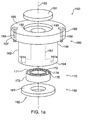
- FIG. 1 shows a replaceable bearing cartridge assembly 150 for use in flywheel energy system 100, constructed in accordance with the principles of this invention.
- System 100 has at least one flywheel 110 having rotor shaft 120 for rotation about rotor axis 130 in housing 140, which encloses flywheel 110.
- Housing 140 includes housing end plates 142, each of which has port 141, which is substantially coaxial with rotor axis 130.
- Bearing cartridge assembly 150 includes at least three elements: hollow bearing cartridge 160, annular bearing 170, and annular bearing retaining ring 180.
- Bearing cartridge 160 has inner surface 161, outer surface 162, longitudinal axis 163, first axial end 164, and second axial end 165.
- portion 166 of outer surface 162 is fixedly mounted to housing end plate 142 at port 141, preferably at least partially in port 141.
- Annular bearing 170 shares the same rotational axis as rotor 120 (e.g., axis 130), has inner surface 171, and outer surface 172.
- Bearing outer surface 172 is mounted to cartridge inner surface 161, preferably near first end 164 so that bearing inner surface 171 at least partially supports rotor shaft 120.
- Annular bearing retaining ring 180 is mounted to the cartridge adjacent the bearing for retaining the bearing in the cartridge. Preferably, ring 180 is mounted at first axial end 164 of cartridge 160.
- Cartridge 160 preferably includes radially flanged portion 167 at second end 165 of cartridge 160.
- Flanged portion 167 may be used to mount and/or fasten assembly 150 to housing end plate 142.
- flanged portion 167 may be fixedly mounted to housing end plate 142 using one or more bolts 168.
- a portion of outer surface 162 of cartridge 160 and port 141 may be provided with mating threads for mounting and unmounting assembly 150 by screwing and unscrewing cartridge 160, respectively.
- Flanged portion 167 could then serve as a mechanical stop, preventing assembly 150 from screwing too far into port 141.
- Flanged portion 167 is especially important so that a used or damaged assembly may be quickly and reproducibly replaced.
- Port 141 and cartridge outer surface 162 may also be tapered along their longitudinal axis.
- an o-ring (not shown), such as a rubber o-ring, may be mounted between flanged portion 167 and housing end plate 142.
- Outer surface 169 of flanged portion 167 may have a substantially cylindrical shape, which can easily be fabricated using conventional lathing techniques.
- outer surface 169 of flanged portion 167 may have a non-cylindrical shape and housing end plate 141 a corresponding recessed portion adapted to receive said flanged portion.
- Second end 165 of hollow cartridge 160 may be open through aperture 190, which has a longitudinal axis that is substantially coaxial with cartridge longitudinal axis 163.
- Aperture 190 provides access to rotor shaft 120, which may be used during installation and replacement of assembly 150.
- assembly 150 may further include cover plate 191 which can be mounted over, or in, aperture 190.
- cover plate o-ring (not shown) may be mounted between cover plate 191 and housing end plate 142 as well.
- aperture 190 has seat 192 adapted to receive cover plate 191.
- Cartridge 160 is preferably made from a relatively hard material, such as steel, especially heat-treated steel, in order to securely hold in place bearing 170 and retaining ring 180.
- bearing retaining ring 180 is preferably made from a relatively soft metal, such as a Babbitt metal, to prevent galling with flywheel 110 if bearing 170 fails.
- retaining ring 180 is also preferably softer than rotor shaft 120.
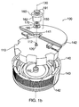
- axis 130 may be oriented vertically and the weight of flywheel 110 may be partially, and possibly substantially, supported by bearing assembly 150', which is located under flywheel 110.
- Bearing assembly 150' may be identical in structure to bearing assembly 150, but oriented in an opposite direction.
- retaining ring 180 is closely spaced from flywheel surface 111. Preferably, that space is a fraction of an inch and decreases with decreasing radial distance. Bearing failure may be catastrophic and may lead to a complete disintegration of weight-supporting bearing 170. In that case, flywheel 110 would fall, contacting retaining ring 180 while rotating at high speed.
- Retaining ring 180 would vertically support and rotationally guide the rotation of flywheel 110 until flywheel 110 came to a stop due to the frictional force between flywheel surface 111 and retaining ring 180.
- the materials from which they are made should have substantially different harnesses.
- retaining ring 180 may include brass, aluminum, bronze, or even a mild steel.
- Cartridge inner surface 161 may have bearing seat 161a at first end 164 for mounting bearing 170 so that bearing outer surface 172 mounts in bearing seat 161a. While many types of annular bearings may be used in accordance with this invention, a deep-groove ball bearing is especially useful, especially when the bearing is mounted below the flywheel for supporting the weight of the flywheel, such as bearing 150' shown in FIG. 1b. In this case, the deep-groove ball bearing should be capable of substantially support an axial force at least equal to the weight of the flywheel. Deep-groove ball bearing 170 includes inner race 173, outer race 174, and plurality of rolling elements 175 captured between races 173 and 179.
- Bearing 170 is retained in cartridge 160 by retaining ring 180, which should be fixedly mounted to cartridge 160, preferably at first end 164 of cartridge 160.
- Retaining ring 180 may be attached to cartridge 160 with one or more screws (not shown) that extend axially between retaining ring 180 and first end 164 of cartridge 160.
- First end 164 of cartridge 160 may be provided with seat 161b in which retaining ring 180 is mounted.
- Retaining ring 180 has first side 181 and second side 182, wherein first portion 181a of first side 181 is mounted at first end 164 of cartridge 160 and second portion 181b of first side 181 prevents bearing 170 from axial motion.
- Flywheel surface 111 at rotor shaft 120 and second side 182 of retaining ring 180 may be curved, as shown in FIGS. 3 and 5.
- the curved surfaces must be spaced so that there is a small radial and axial clearance between them.
- the radial distance between the two surfaces at any axial position near rotor end 112 should be between about 0.1 mm and about 10 mm (e.g., about 1 mm).
- any point on curved flywheel surface 111 has a radial distance that is smaller than the radial distance to any point on second side 182 of retaining ring 180 in the vicinity of rotor end 112.
- any point on flywheel curved surface 111 preferably has a radial distance that decreases axially from flywheel 110 toward rotor shaft end 112.
- bearing assembly 150 An important advantage of bearing assembly 150 is that it may be replaced quickly and easily.
- one or more flywheel energy systems 100 are mounted in a cabinet, each having its own rotor shaft. Therefore, in order to ensure quick and easy bearing assembly replacement, flywheel system 100 should be mounted with sufficient space adjacent to housing end plates 142 to remove and install bearing assemblies 150 and 150' when replacement becomes necessary or desired, without removing flywheel energy system 100 from the cabinet.
- FIGS. 2 and 3 show bearing cartridge assembly puller 200 for a flywheel energy system, such as flywheel energy system 100.
- Puller 200 includes body 210, at least one fastener 220, and threaded pin 230.
- Body 210 has substantially flat surface 212 and threaded passage 214, which has longitudinal axis 163 perpendicular to flat surface 212.
- Fasteners 220 are for fixedly mounting a portion of flat surface 212 to second end 165 of cartridge 160.
- Threaded pin 230 has tip portion 232 and length 233, which is measured from tip portion 232 to its other end 234.
- Pin length 233 is preferably greater than assembly length 236, which is measured from first end 164 to second end 165 of assembly 160.
- Pin 230 matingly engages with threaded passage 214. When pin 230 is rotated, tip portion 232 applies a force to rotor end 112, thereby moving assembly 150 axially away from rotor shaft 120 of flywheel 110.
- puller 200 for removing a bearing cartridge assembly from a flywheel energy system is described.
- assembly 150 is unfastened from housing end plate 142. For example, this may involve rotating bolts 168 until they are removed from their respective bores in cartridge 160.
- bearing cartridge assembly puller 200 is mounted to second end 165 of cartridge 160 at port 141 so that tip portion 232 is disposed against rotor end 112 and flat portion 212 is disposed against second end 165 of cartridge 160.
- threaded pin 230 is rotated so that tip portion 232 freely rotates on rotor end 112.
- Mounting puller 200 to cartridge assembly 150 may include fastening flat portion 212 of puller body 210 to cartridge 160.
- One way in which puller 200 may be fastened includes bolting flat portion 212 of body 210 to cartridge 160.
- tip portion 232 of pin 230 may be inserted into recessed portion 114 of rotor end 120 to prevent radial movement, or slippage.
- this method may further include removing cover plate 191 from assembly 150 before mounting puller 200 on assembly 150. Removal of cover plate 191 provides access to rotor shaft 120.
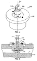
- Assembly pusher 300 includes threaded bolt 310, sleeve 320, and nut 330.
- Threaded bolt 310 has longitudinal axis 314, outer diameter 316, and threaded tip portion 318 for engaging threaded rotor end 120.
- the length of bolt 310 should be sufficiently long so that when tip portion 318 engages rotor end 120, its other end 311 extends above sleeve 320 enough so that nut 330 can be rotatably mounted.
- Sleeve 320 is preferably mounted around bolt 310.
- Sleeve 320 should have an inner diameter greater than outer diameter 316 of bolt 310 so that sleeve 320 can slide freely along longitudinal axis 314 of bolt 310.
- Nut 330 is rotatably mounted on end 311 of bolt 310 so that when nut 330 is rotated in one direction sleeve 320 is forced by nut 330 toward threaded tip portion 318 of bolt 310.
- sleeve 320 presses against bearing assembly 150, and preferably against bearing 170, which in turn pushes bearing assembly 150 over rotor end 120.
- bearing cartridge assembly pusher 300 is mounted inside assembly 150, as shown in FIG. 5.
- threaded bolt 310 is rotated in a first bolt direction (not shown) so that threaded tip portion 318 matingly engages with threaded rotor end 120.
- nut 330 is rotated in a first nut direction (not shown) so that when nut 330 is rotated in that direction sleeve 320 is pushed downward toward threaded tip portion 318.
- sleeve 320 presses against bearing assembly 150, and preferably against bearing 170, which in turn pushes bearing assembly 150 over rotor end 120.
- pusher 300 may be removed by (1) rotating bolt 310 in a direction opposite the first bolt direction until threaded tip portion 318 is not engaged with threaded rotor end 120, and unmounting pusher 300 from rotor end 120 and assembly 150.
- assembly 150 includes removable cover plate 191 (shown in FIGS. 1a and 1b)
- Unmounting pusher 300 may simply involve extracting or removing pusher 300 from the assembly.
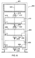
- FIG. 6 shows one embodiment of flywheel energy unit 400 constructed according to the present invention.
- Unit 400 includes three flywheel energy systems 410, 420, and 430 mounted in cabinet 401. As shown in FIG. 6, systems 410, 420, and 430 are mounted along a common vertical rotational axis 403, but each system may be mounted for rotation about different axes if desired. Of course, any number of flywheel systems could be incorporated into a cabinet, provided there exists sufficient space therein.
- flywheel systems 410, 420, and 430 are supported by brace 411, 421, and 431.
- the flywheels (not shown) in the flywheel systems are each supported by two bearing assemblies during operation.
- System 410 for example, includes an upper bearing assembly 412 and a lower bearing assembly (not shown).
- Bearing assembly 412, as shown in FIG. 6, is being pulled from housing end plate 416 by bearing assembly puller 414.
- bearing assembly 412 can be easily removed without removing flywheel 410, as long as sufficient space exists above housing end plate 416.
- System 420 of unit 400 also includes an upper bearing assembly 422 and lower bearing assembly 427.
- Upper assembly 422, as shown in FIG. 6, is being pulled from end plate 426 by bearing assembly puller 424 in a fashion similar to assembly 412.
- Lower bearing assembly 427 is being pushed into lower end plate 429 by bearing assembly pusher 428.
- System 430 of unit 400 also shows lower bearing assembly 434 being pushed into lower end plate 439 by assembly pusher 436.
- FIGS. 3 and 5 show annular bearing 170 having spherical rolling elements 175, those rolling elements may be cylindrical or any other shape that provides reduced friction between inner race 173 and outer race 174. It should also be clear to a person of ordinary skill in the art that retaining ring 180 could retain bearing 170 in cartridge 160 by applying a force from the other side of bearing 170.
- bearing 170 would be inserted from second end 165 of cartridge 160, and the radial thickness of first end 164 would be increased so that a portion of first end 164 would sandwich bearing 170 between first end 164 and retaining ring 180. If first end 164 has a curved surface similar to second side 182 of retaining ring 180, then it could equally serve as a back-up bushing in the event of primary bearing failure.
Landscapes
- Engineering & Computer Science (AREA)
- General Engineering & Computer Science (AREA)
- Mechanical Engineering (AREA)
- Power Engineering (AREA)
- Physics & Mathematics (AREA)
- Acoustics & Sound (AREA)
- Aviation & Aerospace Engineering (AREA)
- Manufacture Of Motors, Generators (AREA)
- Mounting Of Bearings Or Others (AREA)
- Connection Of Motors, Electrical Generators, Mechanical Devices, And The Like (AREA)
- Magnetic Bearings And Hydrostatic Bearings (AREA)
- Replacement Of Web Rolls (AREA)
Claims (32)
- Auswechselbare Lagerkassettenanordnung (150) für ein Schwungrad-Energiesystem (100), wobei das System (100) mindestens ein Schwungrad (110) aufweist, das eine Rotorwelle (120) für eine Drehbewegung um eine Rotorachse (130) in einem Gehäuse (140) mit einer Endplatte (142) aufweist, wobei die Gehäuseendplatte (142) eine Öffnung (141) aufweist, die bezüglich der Rotorachse (130) im wesentlichen koaxial ausgerichtet ist;
wobei die Anordnung (150) aufweist:eine hohle Lagerkassette (160) mit einer Innenfläche (161), einer Außenfläche (162), einer Längsachse (163), einem ersten axialen Ende (164) und einem zweiten axialen Ende (165), wobei ein Abschnitt der Außenfläche (162) an der Gehäuseendplatte (142) an der Öffnung (141) fest montierbar ist;ein ringförmiges Lager (170) mit einer Drehachse, die mit der Längsachse (163) der hohlen Lagerkassette (160) übereinstimmt, einer Innenfläche (171) und einer Außenfläche (172), wobei die Lageraußenfläche (172) in der Nähe des ersten axialen Endes (164) an der Kassetteninnenfläche (161) montiert ist, und wobei die Lagerinnenfläche (171) im Betrieb die Rotorwelle (120) mindestens teilweise hält, wobei die Lagerdrehachse (163) im Betrieb bezüglich der Rotorachse (130) koaxial ausgerichtet ist; undeinen in der Nähe des Lagers (170) an der Kassette (160) montierten ringförmigen Lagerhaltering (180) zum Halten des Lagers (170) in der Kassette (160). - Anordnung nach Anspruch 1, wobei der Ring (180) am ersten axialen Ende (164) der Kassette (160) montiert ist.
- Anordnung nach Anspruch 1, wobei die Kassette (160) am zweiten Ende (165) einen radialen Flanschabschnitt (167) aufweist.
- Anordnung nach Anspruch 3, wobei die Kassette (160) am Flanschabschnitt (167) an der Gehäuseendplatte (142) montierbar ist.
- Anordnung nach Anspruch 4, ferner mit mehreren Bolzen (168), wobei der Flanschabschnitt (167) unter Verwendung der Bolzen (168) fest und stabil an der Gehäuseendplatte (142) montierbar ist.
- Anordnung nach Anspruch 4, wobei die Öffnung (141) ein Gewinde aufweist, und die Kassettenaußenfläche (162) mit einem entsprechenden Gewinde versehen ist, um die Kassette (160) im Betrieb in die Öffnung (141) zu schrauben.
- Anordnung nach Anspruch 4, ferner mit einem Kasseten-O-Ring, der zwischen dem Flanschabschnitt (167) und der Gehäuseendplatte (142) montierbar ist.
- Anordnung nach Anspruch 4, wobei die Öffnung (141) und die Kassettenaußenfläche (162) kegelförmig ausgebildet sind.
- Anordnung nach Anspruch 4, wobei der Flanschabschnitt (167) eine Außenfläche (169) mit einer im wesentlichen zylindrischen Form aufweist.
- Anordnung nach Anspruch 4, wobei die Außenfläche (169) des Flanschabschnitts (167) eine nicht-zylindrische Form hat und die Gehäuseendplatte (142) einen Vertiefungsabschnitt an der Öffnung (141) aufweist, der dazu geeignet ist, den Flanschabschnitt (167) aufzunehmen, um zu verhindern, dass die Kassette (160) sich um die Längsachse (163) dreht.
- Anordnung nach Anspruch 10, wobei der Flanschabschnitt (167) eine polygonale Form hat.
- Anordnung nach Anspruch 4, wobei das zweite Ende (165) durch eine Öffnung (190) mit einer Längsachse offen ist, die sich bezüglich der Kassettenlängsachse (163) im wesentlichen koaxial erstreckt.
- Anordnung nach Anspruch 12, ferner mit einer an der Öffnung (190) montierten Abdeckplatte (191), wobei die Abdeckplatte (191) zum hermetischen Abdichten des Lagers (170) dient.
- Anordnung nach Anspruch 13, ferner mit einem zwischen der Abdeckplatte (191) und der Gehäuseendplatte (142) in der Öffnung (190) montierten (nicht dargestellten) Abdeckplatten-O-Ring.
- Anordnung nach Anspruch 14, wobei das zweite Ende (165) einen Sitz (192) aufweist, der dazu geeignet ist, die Abdeckplatte (191) aufzunehmen.
- Anordnung nach Anspruch 1, wobei die Kassette (160) eine Metallkassette ist.
- Anordnung nach Anspruch 16, wobei die Kassette (160) eine Kassette aus wärmebehandeltem Stahl ist.
- Anordnung nach Anspruch 1, wobei die Kassette (160) eine Kassette aus einem nicht-magnetischen Material ist.
- Anordnung nach Anspruch 16, wobei der Haltering (180) ein Metall aufweist, das weicher ist als die Metallkassette (160).
- Anordnung nach Anspruch 19, wobei der Haltering (180) aus einem Babitt-Metall besteht.
- Anordnung nach Anspruch 17, wobei der Haltering (180) aus einem Material aus der Gruppe umfassend einem weichen unlegierten Stahl, Aluminium, Bronze, Messing oder einer Kombination davon besteht.
- Anordnung nach Anspruch 1, wobei die Kassetteninnenfläche (161) am ersten Ende (164) einen Lagersitz (161a) aufweist und die Lageraußenfläche (172) im Lagersitz (161a) angeordnet ist.
- Anordnung nach Anspruch 1, wobei das Lager (170) ein Rillenkugellager ist.
- Anordnung nach Anspruch 23, wobei das Rillenkugellager (170) im Betrieb eine axiale Kraft aufnehmen kann, die einem Gewicht des Schwungradsystems (100) im wesentlichen gleicht, wenn die Drehachse (163) des Schwungrades im wesentlichen vertikal ausgeruchtet ist.
- Anordnung nach Anspruch 1, wobei das ringförmige Lager (170) einen inneren Laufring (173), ainen äußeren Laufring (174) und mehrere zwischen den Laufringen gehaltens Rollellemente (175) aufweist.
- Anordnung nach Anspruch 1, ferner mit mindestens einem Befestigungselement, wobei das Befestigungselement dazu dient, den Haltering (180) am ersten Ende (164) der Kassette (160) fest zu montieren.
- Anordnung nach Anspruch 26, wobei das Befestigungselement eine Schraube ist, die sich in der axialen Richtung vom Haltering (180) zum ersten Ende (164) der Kassette (160) erstreckt.
- Anordnung nach Anspruch 1, wobei das zweite Ende (165) der Kassette (160) einen Sitz (161b) aufweist, in dem der Haltering (180) angeordnet ist.
- Anordnung nach Anspruch 1, wobei der Haltering (180) eine erste Seite (181) und eine zweite Seite (182) aufweist, wobei ein erster Abschnitt (181a) der ersten Seite am ersten Ende (164) der Kassette (160) montiert ist und ein zweiter Abschnitt (181b) der ersten Seite die axiale Bewegung des Lagers (170) begrenzt.
- Anordnung nach Anspruch 29, wobei die Rotorwelle (120) ein Material aufweist und der Haltering (180) ein Material aufweist, das weicher ist als das Material der Rotorwelle.
- Anordnung nach Anspruch 1, wobei das Schwungrad (110) eine gekrümmte Oberfläche (111) aufweist, die einer gekrümmten Oberfläche des Halterings (180) gegenüberliegt, wodurch ein Zwischenraum dazwischen gebildet wird, wobei der Zwischenraum ausreichend klein ist, um eine wesentliche axiale und radiale Bewegung des Schwungrades (110) zu verhindern, falls das Lager (170) während des Schwungradbetriebs versagt.
- Anordnung nach Anspruch 31, wobei die gekrümmte Schwungradoberfläche (111) eine radiale Abmessung hat, die vom Schwungrad (110) zum Rotorwellenende (112) axial abnimmt.
Applications Claiming Priority (3)
| Application Number | Priority Date | Filing Date | Title |
|---|---|---|---|
| US925548 | 1997-09-08 | ||
| US08/925,548 US6029538A (en) | 1997-09-08 | 1997-09-08 | Replaceable bearing cartridge assembly for flywheel energy system |
| PCT/US1998/018424 WO1999013553A1 (en) | 1997-09-08 | 1998-09-03 | Replaceable bearing cartridge assembly for flywheel energy system |
Publications (2)
| Publication Number | Publication Date |
|---|---|
| EP1012950A1 EP1012950A1 (de) | 2000-06-28 |
| EP1012950B1 true EP1012950B1 (de) | 2006-04-26 |
Family
ID=25451885
Family Applications (1)
| Application Number | Title | Priority Date | Filing Date |
|---|---|---|---|
| EP98944745A Expired - Lifetime EP1012950B1 (de) | 1997-09-08 | 1998-09-03 | Auswechselbarer kassettelagerzusammenbau für ein schwungradenergiesystem |
Country Status (6)
| Country | Link |
|---|---|
| US (1) | US6029538A (de) |
| EP (1) | EP1012950B1 (de) |
| AT (1) | ATE324699T1 (de) |
| AU (1) | AU9221198A (de) |
| DE (1) | DE69834337T2 (de) |
| WO (1) | WO1999013553A1 (de) |
Families Citing this family (24)
| Publication number | Priority date | Publication date | Assignee | Title |
|---|---|---|---|---|
| AT413580B (de) * | 1999-06-10 | 2006-04-15 | Tcg Unitech Ag | Kreiselpumpe |
| US6630761B1 (en) | 2000-08-10 | 2003-10-07 | Christopher W. Gabrys | Combination mechanical and magnetic support for a flywheel power supply |
| US6679634B2 (en) | 2000-12-14 | 2004-01-20 | Ronald L. Plesh, Sr. | Low maintenance easily changeable bearing |
| US7679245B2 (en) | 2001-09-17 | 2010-03-16 | Beacon Power Corporation | Repulsive lift systems, flywheel energy storage systems utilizing such systems and methods related thereto |
| US6794776B1 (en) | 2001-10-15 | 2004-09-21 | Christopher W Gabrys | Inductor alternator flywheel system |
| US20060104559A1 (en) * | 2004-11-17 | 2006-05-18 | Wingett Paul T | Side shields for fractured outer ring bearing |
| CA2686843A1 (en) | 2009-12-02 | 2011-06-02 | Flywheel Energy Systems Inc. | Compliant bearing mount with a position restoring shear force absorber |
| KR101870339B1 (ko) * | 2010-06-08 | 2018-06-22 | 템포럴 파워 리미티드 | 플라이휠 에너지 시스템 |
| GB201200625D0 (en) * | 2012-01-16 | 2012-02-29 | Romax Technology Ltd | Bearing retainer |
| WO2013155598A1 (en) | 2012-04-16 | 2013-10-24 | Temporal Power Ltd. | Method and system for regulating power of an electricity grid system |
| US10995820B2 (en) * | 2012-08-23 | 2021-05-04 | Amber Kinetics, Inc. | Apparatus and method for magnetically unloading a rotor bearing |
| US10240660B2 (en) | 2013-08-22 | 2019-03-26 | Amber Kinetics, Inc. | Safe assembly and installation of a flywheel |
| EP2914826B1 (de) | 2012-11-05 | 2019-10-30 | BC New Energy (Tianjin) Co., Ltd. | Gekühlte schwungradvorrichtung |
| US9735645B2 (en) | 2013-07-08 | 2017-08-15 | Saint Augustin Canada Electric Inc. | Energy storage flywheel device and system for producing kinetic energy within the storage system |
| US9574610B2 (en) | 2013-10-08 | 2017-02-21 | Kice Industries, Inc. | Bearing assembly with outboard bearing support cartridge |
| US9188162B2 (en) | 2013-10-08 | 2015-11-17 | Kice Industries, Inc. | Bearing assembly with spacer for locating a seal sleeve |
| US9083207B1 (en) | 2014-01-10 | 2015-07-14 | Temporal Power Ltd. | High-voltage flywheel energy storage system |
| KR102045340B1 (ko) * | 2015-06-26 | 2019-11-15 | 앰버 카이네틱스, 인크. | 플라이휠의 안전한 조립 및 장착 |
| US11085420B2 (en) | 2017-07-06 | 2021-08-10 | Amber Kinetics, Inc. | Grease channel for reducing gas permeation into vacuum chambers |
| AU2018374733B2 (en) * | 2017-11-28 | 2021-04-22 | Amber Kinetics, Inc. | Apparatus and method for magnetically unloading a rotor bearing |
| IT201800005683A1 (it) * | 2018-05-24 | 2019-11-24 | Giroscopio per stabilizzatore antirollio | |
| GB201815260D0 (en) * | 2018-09-19 | 2018-10-31 | Oxto Ltd | Energy storage system |
| EP4473638A4 (de) | 2022-02-01 | 2025-11-12 | Torus Inc | Mechanische energiespeichereinheit |
| CN121712612A (zh) * | 2023-05-16 | 2026-03-20 | 托乐斯有限公司 | 机械能存储单元和装配夹具 |
Family Cites Families (5)
| Publication number | Priority date | Publication date | Assignee | Title |
|---|---|---|---|---|
| DE2754623A1 (de) * | 1977-12-08 | 1979-06-13 | Maschf Augsburg Nuernberg Ag | Schwungrad |
| US4482194A (en) * | 1983-09-12 | 1984-11-13 | Disposable Waste Systems, Inc. | Fluid pressure assisted rotary shaft seal with labyrinth bushing and replacement seal sleeve cartridge |
| US5390554A (en) * | 1991-10-28 | 1995-02-21 | Honeywell Inc. | Spacecraft component bearing |
| US5715976A (en) * | 1995-07-20 | 1998-02-10 | Tecnetics Industries Inc. | Cartridge bearing assembly for volumetric feeder |
| US5873285A (en) * | 1997-05-13 | 1999-02-23 | Honeywell Inc. | Modular reaction wheel |
-
1997
- 1997-09-08 US US08/925,548 patent/US6029538A/en not_active Expired - Lifetime
-
1998
- 1998-09-03 AT AT98944745T patent/ATE324699T1/de not_active IP Right Cessation
- 1998-09-03 AU AU92211/98A patent/AU9221198A/en not_active Abandoned
- 1998-09-03 EP EP98944745A patent/EP1012950B1/de not_active Expired - Lifetime
- 1998-09-03 DE DE69834337T patent/DE69834337T2/de not_active Expired - Lifetime
- 1998-09-03 WO PCT/US1998/018424 patent/WO1999013553A1/en not_active Ceased
Also Published As
| Publication number | Publication date |
|---|---|
| AU9221198A (en) | 1999-03-29 |
| WO1999013553A1 (en) | 1999-03-18 |
| EP1012950A1 (de) | 2000-06-28 |
| US6029538A (en) | 2000-02-29 |
| DE69834337D1 (de) | 2006-06-01 |
| ATE324699T1 (de) | 2006-05-15 |
| DE69834337T2 (de) | 2006-09-28 |
Similar Documents
| Publication | Publication Date | Title |
|---|---|---|
| EP1012950B1 (de) | Auswechselbarer kassettelagerzusammenbau für ein schwungradenergiesystem | |
| US8979386B2 (en) | Rolling element bearing having replaceable seal | |
| CN111919043B (zh) | 用于在预负载操作期间定位轴承组件的滚动元件的组装工具和方法 | |
| EP2000404B1 (de) | Propellerblattbefestigung mit Kegelrollenlagerkartuschenbaugruppen | |
| EP0126607A2 (de) | Auswechselbarer Lagerzusammenbau und Verfahren zum Zusammenbau | |
| US5373636A (en) | Bearing removal system | |
| US8439573B2 (en) | Replaceable bearing for a conveyor roller | |
| EP4085203B1 (de) | Elektrische maschine, die mit einer lösbaren lageranordnung versehen ist | |
| US7422419B2 (en) | Propeller blade retention system | |
| JPH08510532A (ja) | 車体屈折式車両およびヒンジ組立体 | |
| US5433294A (en) | Geared elevator system | |
| US6966702B2 (en) | Bearing insert and service tools | |
| US6682226B2 (en) | Cylindrical roller bearing with preload capability | |
| US4611503A (en) | Means for removing bearing from crankshaft | |
| US5154518A (en) | Ring structure for bearing chocking assembly | |
| CA2228373C (en) | A bearing and a method of disassembling such a bearing | |
| US6098263A (en) | Apparatus and method for blocking shaft of large scale rotatable assembly | |
| AU702381B2 (en) | Bearing retainer assembly | |
| US7036648B2 (en) | Pre-loaded roller turn roller | |
| JPH06346924A (ja) | 高速スピンドルユニット | |
| CA2007269C (en) | Swaging tool for bearing installation | |
| US10900515B2 (en) | Yaw bearing arrangement | |
| CN115263932A (zh) | 一种汽车轮毂用的圆锥滚子轴承 | |
| US5474387A (en) | Axle bearing positioning system | |
| CN108044566B (zh) | 一种直升机旋翼轴主承力螺母装配方法 |
Legal Events
| Date | Code | Title | Description |
|---|---|---|---|
| PUAI | Public reference made under article 153(3) epc to a published international application that has entered the european phase |
Free format text: ORIGINAL CODE: 0009012 |
|
| 17P | Request for examination filed |
Effective date: 20000407 |
|
| AK | Designated contracting states |
Kind code of ref document: A1 Designated state(s): AT BE CH CY DE DK ES FI FR GB GR IE IT LI LU MC NL PT SE |
|
| 17Q | First examination report despatched |
Effective date: 20010725 |
|
| GRAP | Despatch of communication of intention to grant a patent |
Free format text: ORIGINAL CODE: EPIDOSNIGR1 |
|
| GRAS | Grant fee paid |
Free format text: ORIGINAL CODE: EPIDOSNIGR3 |
|
| GRAA | (expected) grant |
Free format text: ORIGINAL CODE: 0009210 |
|
| AK | Designated contracting states |
Kind code of ref document: B1 Designated state(s): AT BE CH CY DE DK ES FI FR GB GR IE IT LI LU MC NL PT SE |
|
| PG25 | Lapsed in a contracting state [announced via postgrant information from national office to epo] |
Ref country code: NL Free format text: LAPSE BECAUSE OF FAILURE TO SUBMIT A TRANSLATION OF THE DESCRIPTION OR TO PAY THE FEE WITHIN THE PRESCRIBED TIME-LIMIT Effective date: 20060426 Ref country code: IT Free format text: LAPSE BECAUSE OF FAILURE TO SUBMIT A TRANSLATION OF THE DESCRIPTION OR TO PAY THE FEE WITHIN THE PRE;WARNING: LAPSES OF ITALIAN PATENTS WITH EFFECTIVE DATE BEFORE 2007 MAY HAVE OCCURRED AT ANY TIME BEFORE 2007. THE CORRECT EFFECTIVE DATE MAY BE DIFFERENT FROM THE ONE RECORDED.SCRIBED TIME-LIMIT Effective date: 20060426 Ref country code: FI Free format text: LAPSE BECAUSE OF FAILURE TO SUBMIT A TRANSLATION OF THE DESCRIPTION OR TO PAY THE FEE WITHIN THE PRESCRIBED TIME-LIMIT Effective date: 20060426 |
|
| REG | Reference to a national code |
Ref country code: GB Ref legal event code: FG4D |
|
| REG | Reference to a national code |
Ref country code: IE Ref legal event code: FG4D |
|
| REF | Corresponds to: |
Ref document number: 69834337 Country of ref document: DE Date of ref document: 20060601 Kind code of ref document: P |
|
| REG | Reference to a national code |
Ref country code: CH Ref legal event code: NV Representative=s name: BOVARD AG PATENTANWAELTE |
|
| PG25 | Lapsed in a contracting state [announced via postgrant information from national office to epo] |
Ref country code: SE Free format text: LAPSE BECAUSE OF FAILURE TO SUBMIT A TRANSLATION OF THE DESCRIPTION OR TO PAY THE FEE WITHIN THE PRESCRIBED TIME-LIMIT Effective date: 20060726 Ref country code: DK Free format text: LAPSE BECAUSE OF FAILURE TO SUBMIT A TRANSLATION OF THE DESCRIPTION OR TO PAY THE FEE WITHIN THE PRESCRIBED TIME-LIMIT Effective date: 20060726 |
|
| PG25 | Lapsed in a contracting state [announced via postgrant information from national office to epo] |
Ref country code: ES Free format text: LAPSE BECAUSE OF FAILURE TO SUBMIT A TRANSLATION OF THE DESCRIPTION OR TO PAY THE FEE WITHIN THE PRESCRIBED TIME-LIMIT Effective date: 20060806 |
|
| PG25 | Lapsed in a contracting state [announced via postgrant information from national office to epo] |
Ref country code: PT Free format text: LAPSE BECAUSE OF FAILURE TO SUBMIT A TRANSLATION OF THE DESCRIPTION OR TO PAY THE FEE WITHIN THE PRESCRIBED TIME-LIMIT Effective date: 20060926 |
|
| NLV1 | Nl: lapsed or annulled due to failure to fulfill the requirements of art. 29p and 29m of the patents act | ||
| ET | Fr: translation filed | ||
| PLBE | No opposition filed within time limit |
Free format text: ORIGINAL CODE: 0009261 |
|
| STAA | Information on the status of an ep patent application or granted ep patent |
Free format text: STATUS: NO OPPOSITION FILED WITHIN TIME LIMIT |
|
| REG | Reference to a national code |
Ref country code: HK Ref legal event code: WD Ref document number: 1030309 Country of ref document: HK |
|
| 26N | No opposition filed |
Effective date: 20070129 |
|
| PG25 | Lapsed in a contracting state [announced via postgrant information from national office to epo] |
Ref country code: GR Free format text: LAPSE BECAUSE OF FAILURE TO SUBMIT A TRANSLATION OF THE DESCRIPTION OR TO PAY THE FEE WITHIN THE PRESCRIBED TIME-LIMIT Effective date: 20060727 |
|
| PG25 | Lapsed in a contracting state [announced via postgrant information from national office to epo] |
Ref country code: CY Free format text: LAPSE BECAUSE OF FAILURE TO SUBMIT A TRANSLATION OF THE DESCRIPTION OR TO PAY THE FEE WITHIN THE PRESCRIBED TIME-LIMIT Effective date: 20060426 |
|
| PGFP | Annual fee paid to national office [announced via postgrant information from national office to epo] |
Ref country code: IE Payment date: 20090930 Year of fee payment: 12 |
|
| PGFP | Annual fee paid to national office [announced via postgrant information from national office to epo] |
Ref country code: CH Payment date: 20090930 Year of fee payment: 12 |
|
| PGFP | Annual fee paid to national office [announced via postgrant information from national office to epo] |
Ref country code: MC Payment date: 20091002 Year of fee payment: 12 Ref country code: LU Payment date: 20091001 Year of fee payment: 12 Ref country code: AT Payment date: 20091002 Year of fee payment: 12 |
|
| PGFP | Annual fee paid to national office [announced via postgrant information from national office to epo] |
Ref country code: BE Payment date: 20090930 Year of fee payment: 12 |
|
| REG | Reference to a national code |
Ref country code: CH Ref legal event code: PFA Owner name: ACTIVE POWER, INC. Free format text: ACTIVE POWER, INC.#SUITE 135, 11525 STONEHOLLOW DRIVE#AUSTIN, TX 78758 (US) -TRANSFER TO- ACTIVE POWER, INC.#SUITE 135, 11525 STONEHOLLOW DRIVE#AUSTIN, TX 78758 (US) |
|
| BERE | Be: lapsed |
Owner name: *ACTIVE POWER INC. Effective date: 20100930 |
|
| PG25 | Lapsed in a contracting state [announced via postgrant information from national office to epo] |
Ref country code: MC Free format text: LAPSE BECAUSE OF NON-PAYMENT OF DUE FEES Effective date: 20100930 |
|
| REG | Reference to a national code |
Ref country code: CH Ref legal event code: PL |
|
| PG25 | Lapsed in a contracting state [announced via postgrant information from national office to epo] |
Ref country code: IE Free format text: LAPSE BECAUSE OF NON-PAYMENT OF DUE FEES Effective date: 20100903 Ref country code: CH Free format text: LAPSE BECAUSE OF NON-PAYMENT OF DUE FEES Effective date: 20100930 Ref country code: BE Free format text: LAPSE BECAUSE OF NON-PAYMENT OF DUE FEES Effective date: 20100930 Ref country code: LI Free format text: LAPSE BECAUSE OF NON-PAYMENT OF DUE FEES Effective date: 20100930 |
|
| PG25 | Lapsed in a contracting state [announced via postgrant information from national office to epo] |
Ref country code: AT Free format text: LAPSE BECAUSE OF NON-PAYMENT OF DUE FEES Effective date: 20100903 |
|
| PG25 | Lapsed in a contracting state [announced via postgrant information from national office to epo] |
Ref country code: LU Free format text: LAPSE BECAUSE OF NON-PAYMENT OF DUE FEES Effective date: 20100903 |
|
| PGFP | Annual fee paid to national office [announced via postgrant information from national office to epo] |
Ref country code: DE Payment date: 20130919 Year of fee payment: 16 |
|
| PGFP | Annual fee paid to national office [announced via postgrant information from national office to epo] |
Ref country code: FR Payment date: 20130919 Year of fee payment: 16 Ref country code: GB Payment date: 20130919 Year of fee payment: 16 |
|
| REG | Reference to a national code |
Ref country code: DE Ref legal event code: R082 Ref document number: 69834337 Country of ref document: DE |
|
| REG | Reference to a national code |
Ref country code: DE Ref legal event code: R119 Ref document number: 69834337 Country of ref document: DE |
|
| GBPC | Gb: european patent ceased through non-payment of renewal fee |
Effective date: 20140903 |
|
| REG | Reference to a national code |
Ref country code: DE Ref legal event code: R119 Ref document number: 69834337 Country of ref document: DE Effective date: 20150401 |
|
| REG | Reference to a national code |
Ref country code: FR Ref legal event code: ST Effective date: 20150529 |
|
| PG25 | Lapsed in a contracting state [announced via postgrant information from national office to epo] |
Ref country code: DE Free format text: LAPSE BECAUSE OF NON-PAYMENT OF DUE FEES Effective date: 20150401 Ref country code: GB Free format text: LAPSE BECAUSE OF NON-PAYMENT OF DUE FEES Effective date: 20140903 |
|
| PG25 | Lapsed in a contracting state [announced via postgrant information from national office to epo] |
Ref country code: FR Free format text: LAPSE BECAUSE OF NON-PAYMENT OF DUE FEES Effective date: 20140930 |