EP1012939B1 - Anordnung zum verbinden von kabel sowie ein tor für so eine anordnung - Google Patents
Anordnung zum verbinden von kabel sowie ein tor für so eine anordnung Download PDFInfo
- Publication number
- EP1012939B1 EP1012939B1 EP97940476A EP97940476A EP1012939B1 EP 1012939 B1 EP1012939 B1 EP 1012939B1 EP 97940476 A EP97940476 A EP 97940476A EP 97940476 A EP97940476 A EP 97940476A EP 1012939 B1 EP1012939 B1 EP 1012939B1
- Authority
- EP
- European Patent Office
- Prior art keywords
- box
- closing device
- port
- passage
- assembly according
- Prior art date
- Legal status (The legal status is an assumption and is not a legal conclusion. Google has not performed a legal analysis and makes no representation as to the accuracy of the status listed.)
- Expired - Lifetime
Links
- 230000008878 coupling Effects 0.000 title claims abstract description 10
- 238000010168 coupling process Methods 0.000 title claims abstract description 10
- 238000005859 coupling reaction Methods 0.000 title claims abstract description 10
- 230000000712 assembly Effects 0.000 title description 7
- 238000000429 assembly Methods 0.000 title description 7
- 238000005192 partition Methods 0.000 claims description 28
- 239000012528 membrane Substances 0.000 description 11
- 230000000694 effects Effects 0.000 description 4
- 238000000926 separation method Methods 0.000 description 4
- RYGMFSIKBFXOCR-UHFFFAOYSA-N Copper Chemical compound [Cu] RYGMFSIKBFXOCR-UHFFFAOYSA-N 0.000 description 2
- 229910052802 copper Inorganic materials 0.000 description 2
- 239000010949 copper Substances 0.000 description 2
- 230000005611 electricity Effects 0.000 description 2
- 238000009434 installation Methods 0.000 description 2
- 238000011161 development Methods 0.000 description 1
- 230000018109 developmental process Effects 0.000 description 1
- 238000010292 electrical insulation Methods 0.000 description 1
Images


Classifications
-
- H—ELECTRICITY
- H02—GENERATION; CONVERSION OR DISTRIBUTION OF ELECTRIC POWER
- H02G—INSTALLATION OF ELECTRIC CABLES OR LINES, OR OF COMBINED OPTICAL AND ELECTRIC CABLES OR LINES
- H02G3/00—Installations of electric cables or lines or protective tubing therefor in or on buildings, equivalent structures or vehicles
- H02G3/02—Details
- H02G3/08—Distribution boxes; Connection or junction boxes
- H02G3/081—Bases, casings or covers
- H02G3/083—Inlets
-
- H—ELECTRICITY
- H02—GENERATION; CONVERSION OR DISTRIBUTION OF ELECTRIC POWER
- H02G—INSTALLATION OF ELECTRIC CABLES OR LINES, OR OF COMBINED OPTICAL AND ELECTRIC CABLES OR LINES
- H02G3/00—Installations of electric cables or lines or protective tubing therefor in or on buildings, equivalent structures or vehicles
- H02G3/02—Details
- H02G3/08—Distribution boxes; Connection or junction boxes
- H02G3/14—Fastening of cover or lid to box
-
- H—ELECTRICITY
- H02—GENERATION; CONVERSION OR DISTRIBUTION OF ELECTRIC POWER
- H02G—INSTALLATION OF ELECTRIC CABLES OR LINES, OR OF COMBINED OPTICAL AND ELECTRIC CABLES OR LINES
- H02G3/00—Installations of electric cables or lines or protective tubing therefor in or on buildings, equivalent structures or vehicles
- H02G3/02—Details
- H02G3/08—Distribution boxes; Connection or junction boxes
- H02G3/16—Distribution boxes; Connection or junction boxes structurally associated with support for line-connecting terminals within the box
-
- H—ELECTRICITY
- H02—GENERATION; CONVERSION OR DISTRIBUTION OF ELECTRIC POWER
- H02G—INSTALLATION OF ELECTRIC CABLES OR LINES, OR OF COMBINED OPTICAL AND ELECTRIC CABLES OR LINES
- H02G3/00—Installations of electric cables or lines or protective tubing therefor in or on buildings, equivalent structures or vehicles
- H02G3/02—Details
- H02G3/08—Distribution boxes; Connection or junction boxes
- H02G3/18—Distribution boxes; Connection or junction boxes providing line outlets
- H02G3/185—Floor outlets and access cups
Definitions
- the invention relates to an assembly for coupling wires, which assembly is provided with a box comprising chambers, which box comprises at least three ports and one closing device, by means of which the connection from one port to at least one of the other ports can be closed.
- the invention also relates to an assembly for coupling wires, which assembly is provided with a box comprising a chamber, which box comprises at least two ports and a closing device, by means of which the connection between the first port to the second port can closed off from said chamber.
- the box is divided into two spaces by means of a detachable partition plate.
- One space is used for coupling wires intended for telecommunication, and the other space is used for coupling wires intended for alternating voltage.
- the partition plate effects a separation in accordance with statutory standards between the low voltage (for example 12 V) telecommunication wires, and the high voltage (110 V or 230 V) electric wires.
- the partition plate is provided with edge portions, which can be removed only once, thus giving access to the space under the partition plate from surrounding compartments provided with ports.
- the space present under the partition plate can be divided into subspaces by means of a flexible partition strip. Access to the space present above the partition plate from the compartments can be barred by means of cover plates.
- the known assembly has a number of drawbacks.
- the object of the invention is to provide an assembly wherein a port is unequivocally in communication with one of said chambers.
- the box comprises at least two cham bers, which each comprise at least one of said ports, whereby the assembly is furthermore provided with a port comprising said closing device, which is provided on one side with at least two apertures opening into different chambers in the box, and which is provided on a side facing away from the box with a single passage, whereby the closing device can be moved at least from a first position, in which said passage opens into the first chamber and access to the second chamber from said passage is barred, to a second position, in which said passage opens into the second chamber and access to the first chamber from said passage is barred, and vice versa.
- the port comprising the closing device will be in open communication with one chamber, whilst the connection with the other chamber will be closed. As a result of this one port is unequivocally associated with one chamber. If it is desirable to bring the port into communication with the other chamber, it is only necessary to reverse the closing device associated with a respective port. The other wires can be left as they are.
- conduits coupled to the ports and the wires present therein belong to one and the same network, whilst the other conduits coupled to the ports are disconnected from this network.
- One embodiment of the assembly according to the invention is characterized in that wires extend through the closing device in use, whereby the closing device can only be moved from one position to the other after the wires extending through the closing device have been removed.
- wires present in a chamber cannot be accidentally connected to wires present in another chamber.
- the wires must first be removed from the closing device, after which the closing device can be moved and access to another chamber from the passage can be provided. This obliges an operator to change the wiring very consciously.
- Another embodiment of the assembly according to the invention is characterized in that the box is provided with partition walls extending transversely to a bottom portion.
- partition walls extending transversely to the bottom portion provide chambers arranged in adjoining relationship, to which access can be simultaneously gained.
- the chamber present under the partition plate is no longer accessible after the partition plate has been placed. This makes the changing of the wiring a relatively labourious activity.
- Another object of the invention is to provide an assembly for coupling wires, which assembly is provided with a box comprising at least one chamber, which box comprises at least two ports and one closing device, by means of which the connection between the first port and the second port can be closed off from said chamber.
- the object of the invention is to provide an assembly wherein the wires present in the ports may or may not be capable of being connected to wires present in the chamber.
- the box comprises two aligned tube portions making up the ports, whereby the closing device comprises a tubular segment, which can be detachably fitted between said two tube portions.
- tubular segment If the tubular segment is positioned between the tube portions, said tube portions and said tubular segment form an elongated tube, which is closed off from the chamber present within the box.
- the wires present in the tube form part of a network, which is separated from a network present in the chamber in the box. If the tubular segment is removed from the tube portions, the two ports of said tube portions will be in open communication with the chamber in the box and may become part of the same network.
- Figure 1 shows a part of a house in which conduits 1 are provided for wires for electricity distribution, lighting, telephone communication, distribution of television and radio signals, alarm systems, public-address and call installations, sound equipment, computer networks, climate control, access control systems, energy management systems, etc.
- Said wires, which form part of different networks, may be coupled together at certain places, for example for turning on light in dependence on a light intensity measured by means of a sensor, operating a sunshade in dependence on information on the amount of light and the wind force measured by means of light and wind sensors, or controlling electric curtain openers, thermostats, door openers, etc. via an infrared sensor.
- Conduits 1 will be used for selected networks, depending on the wishes of an occupant and future developments.
- conduits I can be adapted to suit other networks.
- the fact is that for safety reasons it is not always permitted to use one and the same conduit for wires of different networks, for example for high voltage and low voltage applications.
- assemblies 2 according to the invention are provided, wherein wires of different networks are electrically separated from each other.
- FIGS 2A-C show a conventional flush junction box 3, which can be built into a wall or a ceiling of a house.
- box 3 Connected to box 3 are various conduits 1, which open into box 3 via ports 4.
- wires (not shown) present within said conduits 1 are interconnected in a desired manner.
- box 3 is closed by means of a cover (not shown), which is connected to the box by means of screws fixed in openings 5.
- FIG 3 shows an assembly 6 according to the invention.
- Said assembly 6 largely corresponds with the flush junction box 3 shown in Figure 2.
- Assembly 6 comprises two parallel conduits 7, however, which are provided with recesses 8 within box 3.
- each conduit 7 comprises two ports 9.
- a tubular cap 10 can be fitted over recess 8, as a result of which conduit 7 extends through box 3, as it were, and does not comprise any ports opening into box 3.
- assembly 6 can be used in a similar manner as box 3 shown in Figure 2, for example for the installation of an electricity network for 230 V. It is also possible, however, to use assembly 6 for high voltage current (230 V) as well as for low voltage current (12 V).
- the wires for the low voltage network are for example laid in left-hand conduit 7, whereby a cap 10 is fitted over recess 8 in conduit 7, as a result of which the low voltage network is electrically separated from the high voltage network in other conduit 7 and conduits 1. If it should be decided at a later stage to have the wires present in conduit 7 form part of the high voltage network as yet, it will only be necessary to remove cap 10 and make the required wire connections. Of course it is also possible to fit a cap 10 over the other conduit 7 and to use the wires present in conduit 7 for a low voltage network.
- FIG 4 shows another embodiment of an assembly 11 according to the invention, box 3 of which largely corresponds with the box shown in Figure 2.
- Box 3 is provided along two opposite side walls with electric connecting blocks 12.
- Aligned conduits 1 can be electrically insulated from the other conduits by means of tubular cap 10.
- Cap 10 is thereby fitted with its ends over the ends of the aligned conduits 1.
- Assembly 11 furthermore comprises an auxiliary box 13, which comprises two mutually separated chambers 14 and 15.
- Auxiliary box 13 can be attached within box 3, whereby the bottom of box 13 is positioned above ports 4.
- Auxiliary box 13 and box 3 can be closed by means of a cover 16.
- Cover 16 is fixed to box 3 by means of screws 17, which are screwed into openings 5 in the box through openings 18 in cover 16.
- assembly 11 The operation of assembly 11 according to the invention is as follows. Electric wires of different networks are electrically separated from each other by means of caps 10. If a lead-through to a space outside assembly 11 is wanted for both networks, the wires of one network are passed through chamber 14 of box 13, whereas the wires of the other network are passed through chamber 15 of auxiliary box 13. In chamber 14 the interconnections of the network present therein can be made. No caps 10 are used for this, but the electric separation takes place in auxiliary box 13. If desired an electric sensor, for example an infrared sensor,-may be placed in chamber 14. If it should be decided at a later stage to use conduits 1 for other networks, a new functional and electric separation of the various networks can be obtained in a simple manner by fitting or removing covers 10 and reorienting the wires in auxiliary box 13.
- Figures 5A-E are a front view and side views respectively of an assembly 20 according to the invention, which comprises a box 21, in which various chambers 23-27 are formed by means of a number of partitions 22. Said partitions 22 are provided with slides 28, by means of which passages between the respective chambers and to conduits 1 present outside box 21 can be selectively opened or closed. Box 21 is provided with three conduits 29 extending through box 21 in parallel relationship, which conduits are each provided with three recesses 8 (not visible) opening into different chambers, which are closed by means of tubular caps 10. The wires of different networks can be accommodated in the respective chambers 23-27.
- the wires present in conduits 29 can be connected to the wires in one of the respective chambers 23-27 by selectively removing covers 10, or be passed through box 21 without interruption. If it should be decided at a later stage to connect the wires in a conduit 29 to wires present in one of the chambers 23-27, it will only be necessary to remove the respective cap 10, as a result of which an aperture to the respective chamber will be formed.
- Box 21 also comprises two ports 4, which can be selectively connected to a chamber positioned on the left of port 4 or to a chamber positioned on the right of port 4 by means of a closing device 30. Closing device 30 will be explained in more detail with reference to Figures 16 and 17.
- Figures 6A-E show another embodiment of an assembly 31 according to the invention comprising a box 32, which is provided along all side walls with a number of conduits 1, which open into box 32 via ports 4.
- Box 32 is divided into a number of chambers 34 by means of partitions 33.
- a trapezoidal chamber 35 adjoining three chambers 34 is provided near the middle port 4 of each side wall of box 32.
- a detachable slide 36 is provided in the partition wall 33 to each adjoining chamber 34, through which chamber 35 can be brought into open communication with the adjoining chamber 34.
- Slides 36 form closing devices, by means of which the passage through a middle conduit 1 via port 4 to a port 4 opening into another chamber 34 can be selectively opened or closed. Selected slides 36 are removed or maintained in dependence on the wires of the various networks present in box 32.
- Figures 7 - 13 show ports which are in particular suitable for being mounted on the outside of a box.
- the ports and closing devices shown in Figures 16 - 19 are suitable for being mounted on the inside as well as on the outside of the box.
- the port 40 shown in Figure 7 is spigot-shaped, whereby port 40 comprises a single passage 41 in a narrower portion, and two apertures 42 on the side of the other, wider portion, which open into different chambers in a box.
- Port 40 is provided near its side comprising aperture 42 with a plate 43, which comprises dovetailed notches 44 on either side.
- Port 40 can be fixed in a recess provided in the box by means of plate 43, whereby the dovetailed notches 44 are brought into engage ment with the edges bounding said recess.
- Port 40 is provided with a tubular closing device 45, which is capable of tilting movement in directions indicated by double arrow PI.
- passage 41 is in open communication with right-hand aperture 42 via channel 46 in closing device 45.
- Left-hand aperture 42 is shut off from passage 41 by closing device 45.
- Passage 41 is provided with flanges 47, against which closing device 45 abuts.
- FIG 8 shows a port 50 according to the invention, which is provided with a closing plate 52, rather than with a closing device 45, which closing plate 52 pivots about a pivot pin 51.
- Closing plate 52 can pivot in directions indicated by double arrow P2, whereby the position of closing plate 52 in which passage 41 is in open communication with the right-hand aperture 42 is illustrated in full lines, and whereby the position of closing plate 52 in which passage 41 is in open communication with the left-hand aperture 42, whilst the passage to right-hand aperture is closed, is illustrated in dotted lines.
- Figure 9 shows a port 60 according to the invention, which is provided with a disc 61 which is capable of rotating movement about an axis.
- Disc 61 comprises a tubular passage 62, which diverges in the shape of a V on one side facing passage 41, and which is bounded by walls 63, 64 on either side.
- disc 61 is rotated in the direction indicated by double arrow P3, until wall 64 abuts against conduit 1.
- left-hand aperture 42 is close by disc 61. If disc 61 is rotated in the opposite direction, an open communication will be effected between left-hand aperture 42 and passage 41, whilst right-hand aperture 42 will be closed.
- the ports 65, 66, 67 illustrated in Figures 10, 11 and 12 correspond with ports 40, 50, 60 respectively illustrated in Figures 7, 8, 9 respectively, whereby ports 65, 66, 67 comprise three apertures 42 instead of two.
- the port 66 shown in Figure 11 comprises two closing plates 52 instead of one, which closing plates are each capable of individual pivoting movement about pivot pins 51, in directions indicated by double arrows P2', P''.
- Figure 13 shows a port 70 according to the invention, which comprises one passage 41 and two apertures 42.
- a elastically deformable conduit 71 is connected to passage 41, which conduit can be buckle from the position illustrated in Figure 13, in which passage 41 is in open communication with left-hand aperture 42, to a position in which passage 41 is in open communication with right-hand aperture 42. Said buckling of conduit 71 may be effected with a screwdriver 72, for example.
- Figures 14A and 14B are a longitudinal sectional view and a front view respectively of a port 75 according to the invention, which comprises two apertures 42.
- Figures 15A and 15B are a longitudinal sectional view and a front view respectively of a port 76, which comprises four apertures 42
- Figures 16A and 16B are a longitudinal sectional view and a front view respectively of a port 77, which comprises three apertures 42. It is possible to have one of the apertures 42 open under a box and connect it directly to a conduit 1.
- Ports 75, 76 and 77 each comprise a single passage 41.
- Plate 43 in which apertures 42 are provided, comprises an aperture 78 which is in line with passage 41, in which aperture a closing device 79 is positioned.
- Closing device 79 extends from aperture 78 to within passage 41.
- Closing device 79 is provided with an elongated tubular element 80, which is longitudinally formed with a slot 81.
- a filling piece 82 provided with a curved slot 83 is positioned within tubular element 80.
- the parts of closing device 79 are shown in more detail in Figures 17A-D, with Figures 17A and C being front views and Figures 17B and D being side views.
- Slot 83 opens into passage 41 on one side, and at its side remote from passage 41 it opens near plate 43.
- Closing device 79 is rotatable in directions indicated by double arrow P4, whereby slot 83 opens in one of the apertures 42 near plate 44 in dependence on the position of closing device 79.
- slot 83 opens into the upper aperture 42.
- a tubular member 84 is positioned between apertures 42 and passage 41, which is provided on four sides with oval apertures 85, into which slot 83 can open.
- Tubular member 84 may also comprise rectangular recesses 86, as is shown in Figure 16A. It is also possible to remove the entire closing device 79 from the port and to replace it by a short tube, through which aperture 78 is brought into open communication with passage 41, and which may serve to pass wires therethrough.
- FIGS 18A-H and 19A-H show ports 90, 91 according to the invention, which are provided with a rectangular frame comprising square passages 92. Each passage 92 is provided with a closing device 93.
- Closing device 93 comprises a tubular member 94 shown in Figures 18C and D, which has a square outside shape to fit passage 92.
- Member 94 comprises a cylindrical passage 96 and a slot 97 extending along one longitudinal side of member 94.
- a filling piece 82 is positioned within member 94, whereby slot 83 provided in filling piece 82 opens into slot 97.
- the side walls 98 of port 90 are provided with recesses which are positioned opposite slot 83.
- Slot 83 opens on the left-hand side or on the right-hand side of the port 90 shown in Figure 18A, depending on the manner in which member 94 is slid into square passage 92. It is also possible to fit a tube 99 in passage 96 instead of filling piece 82, as a result of which a straight passage through port 90 is obtained.
- the port 91 that is shown in Figures 19A-H is different from port 90 in that a tubular element 80 is used instead of a member 94 for fixing element 82 or tube 99.
- Figure 20 shows an assembly 100 according to the invention comprising a box 101 which is divided into two chambers 103, 104 by means of a partition 102. At least two conduits 1 open into each chamber 103, 104. Assembly 100 comprises a port 40 as shown in Figure 7 near one side. Aperture 41 is in open communication with chamber 103 or with chamber 104, depending on the position of closing device 45.
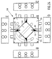
- Figure 21 shows an assembly 105 according to the invention, which comprises a square box 106, into which a number of conduits 1 open.
- Box 106 is divided into four chambers 108 by means of two partitions 107 extending transversely to each other.
- a port 40 as shown in Figure 7 is provided near each end of partitions 107.
- Aperture 41 is in communication with one of the chambers 108, depending on the position of closing device 45.
- left-hand top chamber 108 and right-hand bottom chamber 108 are used for wires carrying 220 V, whilst the bottom left and top right chambers are used for a network which operates on 12 V, for example.
- the chambers belonging to the same network are interconnected by means of conduits 109 and 110 respectively.
- Figures 22A-D show an assembly 115 according to the invention comprising a box 116 which is divided into five chambers.
- Four chambers are in communication with conduits 1, and each of said four chambers is connected to two ports 40 provided with movable closing devices 45.
- Chambers 117 bound a central chamber 118, which may for example accommodate electronics, by means of which the network operating on low voltage current and the network operating on high voltage current are coupled.
- Figures 23A-D show an assembly 120 according to the invention comprising a box 121 which is divided into five chambers.
- a central chamber 122 is in communication with ports 65 as shown in Figure 10 via conduits 123.
- passage 41 can be brought into open communication with a chamber 124 on the right of conduit 123 or with a chamber 124 on the left of conduit 123, or, via conduit 123, to chamber 122, depending on the position of closing device 45.
- Longitudinal sides 125 of chamber 122 are provided with printed circuit boards 126 comprising electronics to be connected to wires present within chambers 124. If desired it is also possible to realise a connection with wires present in chamber 122 via removable slides 127. In this way it is possible to couple an electronic module in assembly 120 to different networks.
- FIGS 24A-E show an assembly 130 according to the invention comprising a box 131 which is divided into five chambers.
- Conduits 133 extend from a central chamber 132 to conduits 1 adjoining box 131.
- a closing device 79 Positioned within each conduit 133 is a closing device 79, as described with reference to Figures 14 - 17.
- Conduit 1 is in communication with a chamber 134 on the left of conduit 133 or with a chamber 134 on the right of said conduit 133, depending on the position of,the channels 83 in closing device 79.
- Closing device 79 can be rotated in directions P4 indicated in Figure 14, for example by means of a screwdriver. It is also possible to remove closing device 79 and replace it by a tube which fits in conduit 133, as a result of which central chamber 132 comes into open communication with a conduit 1.
- FIGS 25A-E show an assembly 140 according to the invention comprising a box 141 which is divided into a number of chambers, and conduits 1 connected thereto.
- Box 141 is provided with conduits 109, 110, which interconnects mutually separated chambers.
- Conduits 109, 110 are located in a portion 142 of box 141 into which no conduits 1 open.
- FIGS 26A-E show an assembly 145 according to the invention comprising a box 146 which is divided into a number of chambers.
- Closing devices 79 can be rotatably operated from a central chamber 147, as a result of which a chamber on the left of closing device 79 or a chamber on the right of closing device 79, depending on the position of closing device 79, is brought into open communication with a conduit 1.
- Each chamber is provided near closing device 79 with a guide element 148 for correctly guiding the wires extending through the port.
- FIG. 27 shows a port 150 according to the invention, which comprises a holder 151 and closing devices 152, 153 which can be mounted within said holder.
- Holder 151 comprises two spaced-apart fastening plates 154, which are each provided on either side with flanges 155 that fit in slots.
- Two passages 156 extend between plates 154, which are separated from each other by a plate 157.
- a block-shaped element 158 in which passages 159 extending transversely to passages 156 are present, extends on an upper side of holder 151.
- Holder 151 is provided on a bottom side with a plate 160 connecting plates 154.
- Closing devices 152 and 153 can be slid into the space bounded by element 158 and plate 157 and into the space bounded by plates 157 and 160.
- Closing device 152 comprises four walls 161 extending parallel and transversely to each other, and one plate 162 disposed diagonally within closing device 152.
- Closing device 153 comprises a rectangular block 163, in which a tubular passage 164 is provided.
- a passage 156 is closed on one side and brought into open communication on the other side with a chamber on the left of port 150 or with a chamber on the right of port 150 (see Figure 28).
- a rectilinear passage through port 150 is obtained.
- Passages 159 in block 158 may be left out, if desired, as a result of which closed walls 165 are obtained.
- FIG 28 shows an application of the port 150 shown in Figure 27.
- An assembly 170 according to the invention comprises a box 171, which is divided into a number of mutually separated chambers 173 by means of a number of partitions 172. Partitions 172 are connected to outside walls 174 of box 171 via ports 150.
- a conduit 1 is in communication with a chamber on the right or on the left of port 150, or with a central chamber 175, depending on whether closing device 152 or closing device 153 is provided in port 150, and depending on the position of closing device 152. Communication between chambers 173 adjoining each other can be effected via apertures 159 in port 150.
- Each partition 172 is provided with a removable slide 176, via which each chamber 173 can be brought into open communication with central chamber 175.
- Box 171 can be closed by means of a cover 177.
- Cover 177 comprises a central auxiliary cover 178, by means of which central chamber 175 can be closed.
- Flanges 179 which are provided with electric terminals 180, extend transversely to auxiliary cover 178.
- Figure 29 shows an assembly 185 according to the invention, which is built up of two boxes 186, 187, which can be coupled together. Said boxes are identical to each other and can be attached together by means of slides 189 to be fitted in slots 188, as a result of which walls 190 of boxes 160, 187 will abut against each other.
- Figure 30 shows a room with an assembly 200 according to the invention fitted in the ceiling, to which conduits 201 and wires 202 are connected.
- Wires 202 are provided with plugs 203, which are inserted into sockets 204 provided in the box.
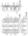
- FIGS 31A and B show a plan view and a side view respectively of an assembly 205 according to the invention, which is provided with a box 206 comprising a number of ports 150. Box 206 is furthermore provided with a number of conduits warping through the box.
- Each conduit 207 comprises two tube portions 208, 209, and a tubular portion 210 interconnecting tube portions 208, 209. Tube portions 208, 209 and tubular segment 210 extend along one and the same radius of curvature and form a through conduit.
- Tubular segment 210 is removed in dependence on the desired use, so that a wire present in tube portion 208 can be pulled into a chamber 211 of box 206, and be connected to other wires present therein. If such a connection is not desired, tubular segment 210 may continue to form part of conduit 207, as a result of which an uninterrupted passage from tube portion 208 to tube portion 209 remains ensured.
- Figures 32A-32C show a similar box 212, which is likewise provided with a curved conduit 207 comprising a tubular porti on 210 detachably accommodated therein.
- Figures 33A-33C are a plan view and side views respectively of a box 213 according to the invention, which is provided with a number of through conduits 214 positioned on a side of the box facing away from the chambers. Said through conduits are fitted with provisions for placing a closing device 152 or 153 as shown in Figure 27, depending on the desired use.
- a wire 215 may extend under the box (see 215') or be guided into a chamber 216 of box 213 (see 215''). Since it is not absolutely necessary to pass wire 215 through box 213, the drawing of the wires is relatively easy.
- Figures 34A-H show another embodiment of an assembly 220 according to the invention, which is provided with a box 221 and two tube portions 222, 223 opening into said box. Tube portions 222, 223 are in line. The ends of tube portions 222, 223 are bevelled, with the tips 224, 225 extending toward each other. Assembly 220 is furthermore provided with two tube portions 226, 227 concentrically surrounding each other, whereby the inside diameter and the outside diameter of tube portions 226 correspond with the inside diameter and the outside diameter of tube portions 222, 223, and tube portion 227 surrounds tube portion 226. The ends of tube portions 226, 227 are bevelled at the same angle as tube portions 222, 223.
- Tube portion 226 is moved into tube portion 227 in the direction indicated by arrow 228 so as to interconnect tube portions 222, 223. Then tube portions 226, 227 are jointly moved in the direction indicated by arrow 229, whereby the bevelled ends come to abut against one another (see Figure 34G). Then tube portion 227 is rotated in the direction indicated by arrow 230, as a result of which tube portion 226 is undetachably connected to tube portions 222, 223, and tube portions 222, 223, 226 form an elongated tube (see Figure 34H, 34D). If the chamber present in box 220 is not needed for fitting a sensor switch or plug socket, tube portions 226, 227 will provide a through conduit.
- tube portions 222, 223 must be removed, after which tube portions 226, 227 can be removed by rotating tube portion 227 in a direction opposed to the direction indicated by arrow 230 and subsequently moving tube portions 226, 227 in a direction opposed to the direction indicated by arrow 229. Then a wire can be provided in tube portions 222, 223 again, which wire may extend to within box 221, whilst the desired sensor or the like may be connected to said wire.
- Figures 35A-C show an assembly 231 according to the invention which is provided with two chambers 232, 233 arranged in adjoining relationship, through which conduits 234-236 extend. Said conduits are provided with closing devices 237, which, depending on the desired use, provide access to chambers 232, 233 from conduits 234-236, or which form a direct passage from conduits 234-236 through assembly 231.
- FIGS 36A-36C show closing devices 240 according to the invention, which are provided with respectively one, two or three elastically deformable, preferably plastic membranes 241.
- Closing device 240 furthermore comprises a plate 242, in which the side edges 243, 244 of membrane 241 are secured. Said side edges are in contact with each other on one side of membrane 241, whilst on the other side of the membrane, near edge 245 of plate 242, said side edges 243, 244 are spaced apart. Near edge 245 of plate 242-a membrane 241 is semi-circular, seen in side view.
- Figures 37A-D show an assembly 247 according to the invention which comprises four closing devices 240, by means of which access can be provided from conduits 248 to a chamber 249 positioned to the left or to the right of a conduit 248, depending on the position of membrane 241.
- Figures 38A-E show an assembly 250 according to the invention, which comprises two chambers 251, 252 and two aligned ports 253, 254.
- Each port 253, 254 is provided with a closing device 240, whereby said ports open into different chambers or can be brought into communication with each other, depending on the position of membrane 241 of closing device 240.
- FIGS 39A-E show an assembly 255 according to the invention, which comprises four chambers 251, 251', 252, 252' and six ports 256 opening into said chambers, which ports are arranged opposite each other in pairs.
- Each port 256 is provided with a closing device 240 comprising a membrane 241, whereby a port 256 can be brought into communication with a chamber 251, 251', 252, 252', depending on the position of membrane 241.
- the ports 256 positioned on the left-hand side and on the right-hand side of chambers 251 and 252 respectively can be interconnected via relatively small chambers 251' and 252', as is illustrated in the left-hand portion of Figure 39A.
- Figures 40A-F show various uses of the boxes shown in the preceding Figures, illustrating various lay-outs for conduits connected to the boxes.
- Figures 41A-C show an assembly 260 according to the invention, which comprises conduits 263 extending transversely to the bottom plate 261 of box 262.
- the conduits 263 opening into the box are provided with a closing device as shown in any one of the preceding Figures, whereby the closing device provides access to one of the chambers 264 from conduit 263, depending on its position.
- Figure 42 is a perspective exploded view of an assembly 265 according to the invention, wherein wires present in each chamber 266 are connected to an electronic circuit 267 associated with the respective chamber 266. Furthermore a sensor or switch 268 or the like is connected to each electronic circuit.
- Figures 43A-B are a plan view and a perspective view respectively of an assembly 270 according to the invention, which comprises a number of chambers 271, 272.
- the diametrically opposite chambers 271 are interconnected via a rectangular, duct-shaped channel 273, through which low voltage wires 274 can be passed.
- the diametrically opposite chambers 272 are interconnected by means of a number of wires 275, for example of copper, which are connected to connectors 276.
- Chambers 272 are preferably used for connecting high voltage wires, whereby it is relatively easy to interconnect the diametrically opposite chambers 272 by means of connectors 276 and copper wires 275.
- Figure 44 shows an assembly 280 according to the invention, which is provided with a cover 281, which can be clamped down in slots 283 of box 284 by means of edges 282.
- said cover 281 is provided with two slotted openings 285, into which an appropriate tool 286 can be inserted. After said tool has been rotated through 90' in the direction indicated by arrow 287, cover 281 can be pulled from box 284. In this manner it is possible to make the box practically entirely flat, so that it is possible to hide the box practically completely from view.
- FIGs 45A-E show an assembly 290 according to the invention, which comprises a port 291, in which a closing device 292 can be placed.
- closing device 292 is provided with two pivotally interconnected wall parts 293, 294, whereby closing device 292 provides access to a single chamber (see Figure 45A) or to two chambers adjoining one another (see Figure 45E), depending on the position of wall part 294.
- Such a closing device is suitable for those applications wherein use is made of two (or more) longitudinally interconnected wires 295, 296.
- closing device 292 is held in the position shown in Figure 45A. The wires 295, 296 are thus guided into one chamber 297 of assembly 290.
- closing device will then be tilted in a direction indicated by arrow 298, as is shown in Figure 45B.
- closing device 292 is provided with a rounded end 299'. After closing device 292 has been removed, wires 295, 296 are partially divided and wire 295 is guided into another chamber 299 of assembly 290.
- closing device 292 which has been removed from assembly 290, is taken hold of by means of a tool 300, whereby wall part 294 is bent over in a direction indicated by arrow 301 to the position illustrated in the right-hand part of Figure 45F.
- adapted closing device 292 is inserted into port 291 again and rotated in the direction indicated by arrow 302 (see Figure 45D) until closing device 292 occupies the position shown in Figure 45E and wires 295, 296 are present in chambers 297, 299, which are electrically separated from each other by means of closing device 292.
- Each of the above ports has specific advantages and disadvantages, whereby a particular port will be selected in dependence on its particular use.
- the differences between the ports concern for example the number of apertures to be selected, the number of conduits to be connected one above the other, the possibility to inspect the position of the closing device visually, the possibility to change the path of the wires once they have been installed, the access to the closing device after the box has been mounted in or on a wall or a ceiling, the manner in which the closing device can be changed over, the electrical insulation of the various chambers with respect to each other, the required amount of space per closing device, etc.
- the box may also be fitted in or on a wall, with the sensors and/or control buttons mounted on the box.
Landscapes
- Engineering & Computer Science (AREA)
- Architecture (AREA)
- Civil Engineering (AREA)
- Structural Engineering (AREA)
- Details Of Indoor Wiring (AREA)
- Installation Of Indoor Wiring (AREA)
- Supports For Pipes And Cables (AREA)
- Cartons (AREA)
- Valve Housings (AREA)
- Connections By Means Of Piercing Elements, Nuts, Or Screws (AREA)
- Paper (AREA)
- Light Guides In General And Applications Therefor (AREA)
Claims (20)
- Baueinheit (2, 6) zum Koppeln von Drähten, welche Baueinheit mit einem Kammern aufweisenden Gehäuse (3, 21) versehen ist, wobei das Gehäuse wenigstens drei Anschlüsse (4, 40, 50, 60) umfasst und eine Schließvorrichtung, mittels welcher die Verbindung von einem Anschluss zu wenigstens einem der anderen Anschlüsse geschlossen werden kann, dadurch gekennzeichnet, dass das Gehäuse wenigstens zwei Kammern (23-27) umfasst, welche jede wenigstens einen der Anschlüsse (4, 40, 50, 60) umfassen, wobei die Baueinheit außerdem mit einem Anschluss versehen ist, der die Schließvorrichtung (30, 45; 62, 60) umfasst, welcher Anschluss auf einer Seite mit wenigstens zwei Öffnungen (42) versehen ist, die in verschiedene Kammern im Gehäuse führen, und welcher auf einer Seite, die vom Gehäuse abgekehrt ist, mit einem einzelnen Gang (41) versehen ist, wobei die Schließvorrichtung (30, 45) wenigstens von einer ersten Position, in welcher der Gang (41) sich in die erste Kammer (103) öffnet und der Zugang zur zweiten Kammer (104) von dem Gang (41) verriegelt ist, in eine zweite Position bewegt werden kann, in welcher der Gang (41) sich in die zweite Kammer (104) öffnet und der Zugag zur ersten Kammer (103) von dem Gang (41) verriegelt ist, und umgekehrt.
- Baueinheit nach Anspruch 1, dadurch gekennzeichnet, dass die Drähte sich beim Gebrauch durch die Schließvorrichtung (30, 45, 52, 60) erstrecken, wobei die Schließvorrichtung nur von einer Position in die andere bewegt werden kann, nachdem die Drähte, welche sich durch die Schließvorrichtung erstrecken, entfernt wurden.
- Baueinheit nach Anspruch 1 oder 2, dadurch gekennzeichnet, dass das Gehäuse mit Trennwänden versehen ist, die sich auerverlaufend zu einem Bodenabschnitt erstrecken.
- Baueinheit nach Anspruch 1, 2 oder 3, dadurch gekennzeichnet, dass die Schließvorrichtung einen Führungsblock umfasst, welcher in dem Anschluss ausbaubar untergebracht ist, welcher Führungsblock mit einem Schlitz versehen ist, welcher in offener Kommunikation mit dem Gang und mit einer der Öffnungen steht.
- Baueinheit nach Anspruch 1, 2 oder 3, dadurch gekennzeichnet, dass die Schließvorrichtung wenigstens eine Platte umfasst, welche mit Anschluss zwischen zwei Öffnungen, die nebeneinander liegen, drehbar verbunden ist und welche sich zu einer Kante des Gangs erstreckt.
- Baueinheit nach Anspruch 1, 2 oder 3, dadurch gekennzeichnet, dass die Schließvorrichtung mit einer elastisch verformbaren Platte versehen ist, welche einen Halbkreisquerschnitt in der Nähe des Gangs aufweist und welche mit dem Anschluss zwischen zwei Öffnungen, die in benachbarten Verhältnis angeordnet sind, drehbar verbunden ist.
- Baueinheit nach Anspruch 1, 2 oder 3, dadurch gekennzeichnet, dass die Schließvorrichtung ein Rohr umfasst, welches zu einer Kippbewegung innerhalb des Anschlusses fähig ist, welches Rohr in offener Kommunikation mit dem Gang mit einem ersten Ende steht und welche in verschiedene Positionen gekippt werden kann, in welchen das zweite Ende des Rohres in Kommunikation mit einer der Öffnungen steht.
- Baueinheit nach Anspruch 1, 2 oder 3, dadurch gekennzeichnet, dass die Schließvorrichtung eine Drehscheibe umfasst, welche versehen ist mit einer Aussparung, die in Kommunikation mit dem Gang ist, und mit einem Kanal, welcher in Kommunikation mit einer der Öffnungen ist, in Abhängigkeit von der Position der Drehscheibe, während die anderen Öffnungen durch die Scheibe geschlossen sind.
- Baueinheit nach Anspruch 1, 2 oder 3, dadurch gekennzeichnet, dass die Schließvorrichtung eine elastisch verformbare Rohrleitung umfasst, welche in verschiedene Positionen geknickt werden kann, wobei ein Ende der Rohrleitung in offener Kommunikation mit dem Gang ist und ein anderes Ende der Rohrleitung in Kommunikation mit einer der Öffnungen in jeder der Positionen steht.
- Baueinheit nach Anspruch 1, 2 oder 3, dadurch gekennzeichnet, dass die Schließvorrichtung einen Führungsblock umfasst, welcher im Gang drehbar gelagert ist und welcher mit einem Schlitz versehen ist, welcher in offener Kommunikation mit einer der Öffnungen steht.
- Baueinheit zum Koppeln von Drähten, wobei die Baueinheit mit einem wenigstens eine Kammer aufweisenden Gehäuse (3) versehen ist, wobei das Gehäuse wenigstens zwei Anschlüsse (4) und eine Schließvorrichtung umfasst, mittels welcher die Verbindung zwischen dem ersten Anschluss und dem zweiten Anschluss von der Kammer abgesperrt werden kann, dadurch gekennzeichnet, dass das Gehäuse zwei ausgerichtete Rohrabschnitte (1) umfasst, welche die Anschlüsse bilden, wobei die Schließvorrichtung ein Rohrsegment (10) umfasst, welches zwischen den beiden Rohrabschnitten (1) ausbaubar eingepasst werden kann.
- Baueinheit nach Anspruch 11, dadurch gekennzeichnet, dass die Rohrabschnitte wenigstens teilweise miteinander verbunden sind.
- Baueinheit nach Anspruch 11 oder 12, dadurch gekennzeichnet, dass die Rohrabschnitte gekrümmt sind, wobei die Rohrabschnitte und das Rohrsegment sich entlang ein und demselben Krümmungsradius erstrecken.
- Baueinheit nach einem der vorhergehenden Ansprüche 11 bis 13, dadurch gekennzeichnet, dass die Enden der Rohrabschnitte, die zueinander gekehrt sind, abgeschrägt sind, wobei die Spitzen sich zueinander erstrecken, während das Rohrsegment zwei koaxiale Teile umfasst, die mit abgeschrägten Enden versehen sind, wobei der innere Abschnitt zwischen den abgeschrägten Enden der Rohrabschnitte angeordnet werden kann, wonach das zweite Teil um das erste Teil gedreht werden kann, um das erste Teil gegen die Rohrabschnitte zu versperren.
- Baueinheit nach einem der vorhergehenden Ansprüche 11 bis 13, dadurch gekennzeichnet, dass die Schließvorrichtung mit wenigstens einem Führungsblock versehen ist, welcher zwischen den Anschlüssen ausbaubar untergebracht ist, dass der Führungsblock mit einem Schlitz versehen ist, welcher entweder in offener Kommunikation mit beiden Anschlüssen oder mit einem Anschluss steht, und einem Raum, der innerhalb des Gehäuses vorhanden ist.
- Baueinheit nach einem der vorhergehenden Ansprüche, dadurch gekennzeichnet, dass das Gehäuse einen Raum umfasst, welcher zentral zwischen den Kammern angeordnet ist.
- Baueinheit nach einem der vorhergehenden Ansprüche, dadurch gekennzeichnet, dass Kammern, die durch eine anders Kammer voneinander getrennt sind, über eine Kopplungsleitung in offener Kommunikation miteinander stehen.
- Baueinheit nach einem der vorhergehenden Ansprüche, dadurch gekennzeichnet, dass der Anschluss mit dem Gehäuse lösbar verbunden ist.
- Baueinheit nach einem der vorhergehenden Ansprüche, dadurch gekennzeichnet, dass das Gehäuse ein schließbares Zusatzgehäuse umfasst.
- Anschluss, der geeignet ist, in einer Baueinheit gemäß einem der vorhergehenden Ansprüche verwendet zu werden.
Applications Claiming Priority (3)
| Application Number | Priority Date | Filing Date | Title |
|---|---|---|---|
| NL1004003A NL1004003C2 (nl) | 1996-09-11 | 1996-09-11 | Samenstel voor het koppelen van bekabeling, alsmede poort voor een dergelijk samenstel. |
| NL1004003 | 1996-09-11 | ||
| PCT/NL1997/000517 WO1998011638A1 (en) | 1996-09-11 | 1997-09-11 | Assemblies for coupling wires, as well as a port for such an assembly |
Publications (2)
| Publication Number | Publication Date |
|---|---|
| EP1012939A1 EP1012939A1 (de) | 2000-06-28 |
| EP1012939B1 true EP1012939B1 (de) | 2002-12-04 |
Family
ID=19763492
Family Applications (1)
| Application Number | Title | Priority Date | Filing Date |
|---|---|---|---|
| EP97940476A Expired - Lifetime EP1012939B1 (de) | 1996-09-11 | 1997-09-11 | Anordnung zum verbinden von kabel sowie ein tor für so eine anordnung |
Country Status (7)
| Country | Link |
|---|---|
| EP (1) | EP1012939B1 (de) |
| AT (1) | ATE229240T1 (de) |
| AU (1) | AU4224297A (de) |
| DE (1) | DE69717682T2 (de) |
| ES (1) | ES2191194T3 (de) |
| NL (1) | NL1004003C2 (de) |
| WO (1) | WO1998011638A1 (de) |
Cited By (1)
| Publication number | Priority date | Publication date | Assignee | Title |
|---|---|---|---|---|
| EP3782234A4 (de) * | 2018-04-18 | 2022-01-05 | Tadpole Products, LLC | System für einen elektronischen türrahmen |
Families Citing this family (1)
| Publication number | Priority date | Publication date | Assignee | Title |
|---|---|---|---|---|
| NL1033064C2 (nl) * | 2006-12-15 | 2008-06-17 | Attema Kunststoffenind | Doos voor geleiders van te scheiden stroomketens. |
Family Cites Families (3)
| Publication number | Priority date | Publication date | Assignee | Title |
|---|---|---|---|---|
| US3110753A (en) * | 1960-09-01 | 1963-11-12 | William W Witort | Conduit raceway system and components therefor |
| US4455449A (en) * | 1982-03-15 | 1984-06-19 | Emerson Electric Co. | Universal high/low voltage kit for junction wiring box |
| US5362922A (en) * | 1992-09-30 | 1994-11-08 | Thomas & Betts Corporation | Electrical floor box divider |
-
1996
- 1996-09-11 NL NL1004003A patent/NL1004003C2/nl not_active IP Right Cessation
-
1997
- 1997-09-11 ES ES97940476T patent/ES2191194T3/es not_active Expired - Lifetime
- 1997-09-11 EP EP97940476A patent/EP1012939B1/de not_active Expired - Lifetime
- 1997-09-11 WO PCT/NL1997/000517 patent/WO1998011638A1/en not_active Ceased
- 1997-09-11 DE DE69717682T patent/DE69717682T2/de not_active Expired - Fee Related
- 1997-09-11 AU AU42242/97A patent/AU4224297A/en not_active Abandoned
- 1997-09-11 AT AT97940476T patent/ATE229240T1/de not_active IP Right Cessation
Cited By (1)
| Publication number | Priority date | Publication date | Assignee | Title |
|---|---|---|---|---|
| EP3782234A4 (de) * | 2018-04-18 | 2022-01-05 | Tadpole Products, LLC | System für einen elektronischen türrahmen |
Also Published As
| Publication number | Publication date |
|---|---|
| AU4224297A (en) | 1998-04-02 |
| NL1004003C2 (nl) | 1998-03-12 |
| DE69717682T2 (de) | 2003-10-16 |
| DE69717682D1 (de) | 2003-01-16 |
| EP1012939A1 (de) | 2000-06-28 |
| ATE229240T1 (de) | 2002-12-15 |
| WO1998011638A1 (en) | 1998-03-19 |
| ES2191194T3 (es) | 2003-09-01 |
Similar Documents
| Publication | Publication Date | Title |
|---|---|---|
| US4875871A (en) | Modular electrical conductor system | |
| US5397929A (en) | Integrated outlet for communications and electrical power | |
| US5445539A (en) | Electrical wiring device for power control with low voltage input | |
| US6777611B2 (en) | Switch/power drop unit for modular wiring system | |
| US20030236011A1 (en) | Electrical distribution terminal guard | |
| US10368458B2 (en) | Rail-mounted control system with improved mounting | |
| US5659151A (en) | Wire management knockout closure for electrical boxes | |
| EP0717425B1 (de) | Differenzielles Schutzmodul mit multipolarem Schaltblock mit Sicherheitskupplung zur Ankupplung an den multipolaren Schaltblock | |
| EP4498541A1 (de) | Anschlussdose für schaltanlage und schaltanlage | |
| HK1005761A1 (en) | Mounting element for installation channel | |
| HK1005761B (en) | Mounting element for installation channel | |
| EP1012939B1 (de) | Anordnung zum verbinden von kabel sowie ein tor für so eine anordnung | |
| US8383937B2 (en) | Auxiliary support case for at least one piece of electrical equipment | |
| US8017881B2 (en) | Side entry circuit breaker | |
| US5557498A (en) | Switching apparatus including a displaceable disconnecting device and an auxiliary circuit | |
| US9692213B2 (en) | Doorless modular panelboard | |
| JPS58126686A (ja) | 接続可能なアダプタを備えた集電レ−ル | |
| EP0757367B1 (de) | Schaltsystem mit Anschlussklemmenmodulen | |
| US7238882B2 (en) | Low voltage door switch | |
| HU225923B1 (en) | Electrical connection device for two electrical apparatus such as an electrical protection device combined with a controlled switch, and electrical apparatus adapted to such device. | |
| JPH11260507A (ja) | 電気接続器 | |
| JPH05304712A (ja) | 配線装置 | |
| JPH07111717A (ja) | 屋内配線器具 | |
| EP1386379B1 (de) | Verbesserte elektrische verteilerdose | |
| US20060043796A1 (en) | AC wall receptacle with integral DC power supply |
Legal Events
| Date | Code | Title | Description |
|---|---|---|---|
| PUAI | Public reference made under article 153(3) epc to a published international application that has entered the european phase |
Free format text: ORIGINAL CODE: 0009012 |
|
| 17P | Request for examination filed |
Effective date: 19990202 |
|
| AK | Designated contracting states |
Kind code of ref document: A1 Designated state(s): AT BE CH DE DK ES FI FR GB GR IE IT LI LU MC NL PT SE |
|
| AX | Request for extension of the european patent |
Free format text: AL PAYMENT 19990202;LT PAYMENT 19990202;LV PAYMENT 19990202;RO PAYMENT 19990202;SI PAYMENT 19990202 |
|
| 17Q | First examination report despatched |
Effective date: 20010307 |
|
| GRAG | Despatch of communication of intention to grant |
Free format text: ORIGINAL CODE: EPIDOS AGRA |
|
| GRAG | Despatch of communication of intention to grant |
Free format text: ORIGINAL CODE: EPIDOS AGRA |
|
| GRAH | Despatch of communication of intention to grant a patent |
Free format text: ORIGINAL CODE: EPIDOS IGRA |
|
| GRAH | Despatch of communication of intention to grant a patent |
Free format text: ORIGINAL CODE: EPIDOS IGRA |
|
| GRAA | (expected) grant |
Free format text: ORIGINAL CODE: 0009210 |
|
| AK | Designated contracting states |
Kind code of ref document: B1 Designated state(s): AT BE CH DE DK ES FI FR GB GR IE IT LI LU MC NL PT SE |
|
| AX | Request for extension of the european patent |
Free format text: AL PAYMENT 19990202;LT PAYMENT 19990202;LV PAYMENT 19990202;RO PAYMENT 19990202;SI PAYMENT 19990202 |
|
| PG25 | Lapsed in a contracting state [announced via postgrant information from national office to epo] |
Ref country code: LI Free format text: LAPSE BECAUSE OF FAILURE TO SUBMIT A TRANSLATION OF THE DESCRIPTION OR TO PAY THE FEE WITHIN THE PRESCRIBED TIME-LIMIT Effective date: 20021204 Ref country code: GR Free format text: LAPSE BECAUSE OF FAILURE TO SUBMIT A TRANSLATION OF THE DESCRIPTION OR TO PAY THE FEE WITHIN THE PRESCRIBED TIME-LIMIT Effective date: 20021204 Ref country code: FI Free format text: LAPSE BECAUSE OF FAILURE TO SUBMIT A TRANSLATION OF THE DESCRIPTION OR TO PAY THE FEE WITHIN THE PRESCRIBED TIME-LIMIT Effective date: 20021204 Ref country code: CH Free format text: LAPSE BECAUSE OF FAILURE TO SUBMIT A TRANSLATION OF THE DESCRIPTION OR TO PAY THE FEE WITHIN THE PRESCRIBED TIME-LIMIT Effective date: 20021204 Ref country code: AT Free format text: LAPSE BECAUSE OF FAILURE TO SUBMIT A TRANSLATION OF THE DESCRIPTION OR TO PAY THE FEE WITHIN THE PRESCRIBED TIME-LIMIT Effective date: 20021204 |
|
| REF | Corresponds to: |
Ref document number: 229240 Country of ref document: AT Date of ref document: 20021215 Kind code of ref document: T |
|
| REG | Reference to a national code |
Ref country code: GB Ref legal event code: FG4D |
|
| REG | Reference to a national code |
Ref country code: CH Ref legal event code: EP |
|
| REG | Reference to a national code |
Ref country code: IE Ref legal event code: FG4D |
|
| REF | Corresponds to: |
Ref document number: 69717682 Country of ref document: DE Date of ref document: 20030116 |
|
| PG25 | Lapsed in a contracting state [announced via postgrant information from national office to epo] |
Ref country code: SE Free format text: LAPSE BECAUSE OF FAILURE TO SUBMIT A TRANSLATION OF THE DESCRIPTION OR TO PAY THE FEE WITHIN THE PRESCRIBED TIME-LIMIT Effective date: 20030304 Ref country code: DK Free format text: LAPSE BECAUSE OF FAILURE TO SUBMIT A TRANSLATION OF THE DESCRIPTION OR TO PAY THE FEE WITHIN THE PRESCRIBED TIME-LIMIT Effective date: 20030304 |
|
| PG25 | Lapsed in a contracting state [announced via postgrant information from national office to epo] |
Ref country code: PT Free format text: LAPSE BECAUSE OF FAILURE TO SUBMIT A TRANSLATION OF THE DESCRIPTION OR TO PAY THE FEE WITHIN THE PRESCRIBED TIME-LIMIT Effective date: 20030305 |
|
| LTIE | Lt: invalidation of european patent or patent extension |
Effective date: 20021204 |
|
| REG | Reference to a national code |
Ref country code: CH Ref legal event code: PL |
|
| ET | Fr: translation filed | ||
| REG | Reference to a national code |
Ref country code: ES Ref legal event code: FG2A Ref document number: 2191194 Country of ref document: ES Kind code of ref document: T3 |
|
| PG25 | Lapsed in a contracting state [announced via postgrant information from national office to epo] |
Ref country code: LU Free format text: LAPSE BECAUSE OF NON-PAYMENT OF DUE FEES Effective date: 20030911 Ref country code: IE Free format text: LAPSE BECAUSE OF NON-PAYMENT OF DUE FEES Effective date: 20030911 |
|
| PG25 | Lapsed in a contracting state [announced via postgrant information from national office to epo] |
Ref country code: MC Free format text: LAPSE BECAUSE OF NON-PAYMENT OF DUE FEES Effective date: 20030930 |
|
| PLBE | No opposition filed within time limit |
Free format text: ORIGINAL CODE: 0009261 |
|
| STAA | Information on the status of an ep patent application or granted ep patent |
Free format text: STATUS: NO OPPOSITION FILED WITHIN TIME LIMIT |
|
| 26N | No opposition filed |
Effective date: 20030905 |
|
| REG | Reference to a national code |
Ref country code: IE Ref legal event code: MM4A |
|
| PGFP | Annual fee paid to national office [announced via postgrant information from national office to epo] |
Ref country code: GB Payment date: 20050613 Year of fee payment: 9 |
|
| PGFP | Annual fee paid to national office [announced via postgrant information from national office to epo] |
Ref country code: FR Payment date: 20050720 Year of fee payment: 9 |
|
| PGFP | Annual fee paid to national office [announced via postgrant information from national office to epo] |
Ref country code: ES Payment date: 20050922 Year of fee payment: 9 |
|
| NLS | Nl: assignments of ep-patents |
Owner name: WARBELL HOLDING B.V. Effective date: 20050829 |
|
| PGFP | Annual fee paid to national office [announced via postgrant information from national office to epo] |
Ref country code: IT Payment date: 20060930 Year of fee payment: 10 |
|
| GBPC | Gb: european patent ceased through non-payment of renewal fee |
Effective date: 20060911 |
|
| REG | Reference to a national code |
Ref country code: FR Ref legal event code: ST Effective date: 20070531 |
|
| PG25 | Lapsed in a contracting state [announced via postgrant information from national office to epo] |
Ref country code: GB Free format text: LAPSE BECAUSE OF NON-PAYMENT OF DUE FEES Effective date: 20060911 |
|
| REG | Reference to a national code |
Ref country code: ES Ref legal event code: FD2A Effective date: 20060912 |
|
| PG25 | Lapsed in a contracting state [announced via postgrant information from national office to epo] |
Ref country code: ES Free format text: LAPSE BECAUSE OF NON-PAYMENT OF DUE FEES Effective date: 20060912 |
|
| PGFP | Annual fee paid to national office [announced via postgrant information from national office to epo] |
Ref country code: DE Payment date: 20071025 Year of fee payment: 11 Ref country code: BE Payment date: 20070905 Year of fee payment: 11 |
|
| PG25 | Lapsed in a contracting state [announced via postgrant information from national office to epo] |
Ref country code: FR Free format text: LAPSE BECAUSE OF NON-PAYMENT OF DUE FEES Effective date: 20061002 |
|
| BERE | Be: lapsed |
Owner name: *WATERS BEHEER B.V. Effective date: 20080930 |
|
| PG25 | Lapsed in a contracting state [announced via postgrant information from national office to epo] |
Ref country code: BE Free format text: LAPSE BECAUSE OF NON-PAYMENT OF DUE FEES Effective date: 20080930 |
|
| PG25 | Lapsed in a contracting state [announced via postgrant information from national office to epo] |
Ref country code: IT Free format text: LAPSE BECAUSE OF NON-PAYMENT OF DUE FEES Effective date: 20070911 Ref country code: DE Free format text: LAPSE BECAUSE OF NON-PAYMENT OF DUE FEES Effective date: 20090401 |
|
| PGFP | Annual fee paid to national office [announced via postgrant information from national office to epo] |
Ref country code: NL Payment date: 20110929 Year of fee payment: 15 |
|
| REG | Reference to a national code |
Ref country code: NL Ref legal event code: V1 Effective date: 20130401 |
|
| PG25 | Lapsed in a contracting state [announced via postgrant information from national office to epo] |
Ref country code: NL Free format text: LAPSE BECAUSE OF NON-PAYMENT OF DUE FEES Effective date: 20130401 |