EP1012002B1 - Covering element for a vehicle loading compartment - Google Patents
Covering element for a vehicle loading compartment Download PDFInfo
- Publication number
- EP1012002B1 EP1012002B1 EP98952602A EP98952602A EP1012002B1 EP 1012002 B1 EP1012002 B1 EP 1012002B1 EP 98952602 A EP98952602 A EP 98952602A EP 98952602 A EP98952602 A EP 98952602A EP 1012002 B1 EP1012002 B1 EP 1012002B1
- Authority
- EP
- European Patent Office
- Prior art keywords
- suitcase
- cover according
- lid
- vehicle
- cover
- Prior art date
- Legal status (The legal status is an assumption and is not a legal conclusion. Google has not performed a legal analysis and makes no representation as to the accuracy of the status listed.)
- Expired - Lifetime
Links
- 235000013361 beverage Nutrition 0.000 claims description 4
- 238000005192 partition Methods 0.000 claims description 3
- 230000000717 retained effect Effects 0.000 claims 1
- 230000006835 compression Effects 0.000 description 4
- 238000007906 compression Methods 0.000 description 4
- 238000010276 construction Methods 0.000 description 4
- 230000008901 benefit Effects 0.000 description 3
- 230000004308 accommodation Effects 0.000 description 2
- 238000009434 installation Methods 0.000 description 2
- 240000008415 Lactuca sativa Species 0.000 description 1
- 230000000295 complement effect Effects 0.000 description 1
- 230000005611 electricity Effects 0.000 description 1
- 238000010438 heat treatment Methods 0.000 description 1
- 239000007788 liquid Substances 0.000 description 1
- 230000007246 mechanism Effects 0.000 description 1
- 239000002245 particle Substances 0.000 description 1
- 235000021178 picnic Nutrition 0.000 description 1
- 238000009420 retrofitting Methods 0.000 description 1
- 235000012045 salad Nutrition 0.000 description 1
Images


Classifications
-
- B—PERFORMING OPERATIONS; TRANSPORTING
- B60—VEHICLES IN GENERAL
- B60R—VEHICLES, VEHICLE FITTINGS, OR VEHICLE PARTS, NOT OTHERWISE PROVIDED FOR
- B60R5/00—Compartments within vehicle body primarily intended or sufficiently spacious for trunks, suit-cases, or the like
- B60R5/04—Compartments within vehicle body primarily intended or sufficiently spacious for trunks, suit-cases, or the like arranged at rear of vehicle
- B60R5/044—Compartments within vehicle body primarily intended or sufficiently spacious for trunks, suit-cases, or the like arranged at rear of vehicle luggage covering means, e.g. parcel shelves
- B60R5/045—Compartments within vehicle body primarily intended or sufficiently spacious for trunks, suit-cases, or the like arranged at rear of vehicle luggage covering means, e.g. parcel shelves collapsible or transformable
Definitions
- the invention relates to a cover for a vehicle hold according to the Preamble of claim 1.
- Such covers are known for example from DE-3734774-A1 (B60R 7/04).
- the cover is as Rear parcel shelf, which offers good storage options in the vehicle Accessibility added.
- the cover is designed as a parcel shelf that extends between the rear seats and the rear window of a motor vehicle.
- a shelf In the a shelf is used as the interior shelf element, which can be closed by a lid.
- the lid is more uniform Part of the parcel shelf trim.
- the parcel shelf itself is designed as a support part and only covers the storage tray with a small proportion of its surface.
- DE-4442042-A1 and EP-0556100-B1 (both B60R 7/02) each show one as Accumulator running container that is in an area in the front upper Section of the trunk of a vehicle is attached.
- the Huboder style The swiveling drawer is accessible when the trunk lid is open and can be used to store a wide variety of objects.
- the one shown there Container arrangement limits the height of the storage space, even if the disadvantage is due to a Storage space height adjustment can be eliminated at least temporarily.
- DE 29508382-U1 (B 60 R 7/00) shows a stationary under as a transport container a vehicle roof hanging storage box, which after its removal from the Mounting position can be used as a portable transport box and can be carried like a suitcase is trained.
- a transport container Motorhomes, caravans, campers in general, coaches and also Airplanes considered, overall very large vehicles.
- DE 3407299-A1 (B 60 R 11/02) shows a rear shelf that acts as a carrier part for a vehicle-specific loudspeaker box can be used.
- WO 97/22495 shows a cover for a vehicle hold Rear seats and tailgate reciprocating roller blind construction. This in different locking positions lockable end piece of the blind arrangement is as Storage tray executed from the vehicle interior or with the tailgate open can also be filled by a person standing behind the vehicle. It will thus an additional storage space created in such roller blind constructions is not actually present in the vehicle. The usable storage volume is however very low.
- the invention has for its object generic covers while preserving improve their benefits.
- the invention according to claim 1 provides at least one position changeable Transport handle in front of which the removal of the cover from the vehicle and also facilitates reinstallation after use outside the vehicle, the transport handle when moving from its rest position into a use position at the same time Case bottom and the case lid locked together.
- the transport handle can be considered largely design-resistant molded part or in the manner of a strip tape.
- covers according to claim 14 of Advantage By at least partially resetting and / or tilting the The bottom of the case can be compared to conventional covers the distance to the loading sill the vehicle is enlarged and thus its loadability can be improved without noteworthy storage options are taken from the cover itself. That in this Trap reduced storage volume in the cover is still sufficient for that Storage of small parts (e.g. tools etc.) or flat objects (e.g. cards etc.).
- This variant can advantageously be combined with the solution according to claim 1.
- the development of the invention according to claim 16 is for retrofitting, handling and Accurate or rattle-free accommodation in the vehicle is of particular importance.
- the detachable insert by means of trunnions is designed so that in the installed position Case lid alone between at least one open position and one closed position can be operated or the case lid together with the case bottom from the installed position can be moved out. This ensures that the accessibility of the transport container both with the cover arranged inside the vehicle and with cover removed from the vehicle is guaranteed. So that can also one and the same cover on the one hand as separable from the vehicle Transport case and other than by hand or from the tailgate Drawstring hinged luggage compartment cover can be used. With this
- the case lid can also be configured as an interior trim part and / or vehicle accessory part be carried out.
- the case bottom acts as a Hold bulkhead.
- the case lid is therefore an essential variation feature, due to the essentially identical covers on the one hand Vehicle interior design can be coordinated and secondly customer-specific Desires for accessories such as speakers or the like are achievable.
- the case bottom can be used for different equipment options of a vehicle series as a standard part because it is in the normal driving of the vehicle is usually not visible.
- the concept of the invention also allows the use of already in Vehicle hat racks or luggage racks as a trunk lid.
- case bottoms are designed so that on the one hand in the Storage fixtures of the load compartment walls originally set up for the rear shelf can be used and on the other hand the existing storage elements make storage elements available to the rear shelf.
- the cover designed according to the invention in marketed in different ways.
- the Sale of a subsystem that is essentially the bottom of the case and thus the Contains bulkhead functions.
- This case bottom is on the Installation conditions of a certain vehicle series matched and can be without further inserted as a drawer or swivel flap in existing storage become. The customer can then use the existing rear shelf part with this Connect basic equipment.
- a complete system can be offered that the case bottom and Covered trunk together. The complete system itself can do the same installation are offered in different user versions.
- a cover designed as an emergency case can be provided, which is at least prepared to hold first aid kits and warning triangles and if necessary, also has on-board tools in order.
- systems can be used that cover at least parts of the cover in the manner of a Baby changing bag, a picnic basket, a camping set, a hobby case or something similar.
- vehicles that are already for First aid kits and warning triangles have suitable accommodation available, can transport containers tailored to selected target groups Tobe offered.
- the cover As a further development of the invention is usability of the cover as a sound and / or image display device equally inside and outside the vehicle intended. This is different from the solution shown in DE 3407299-A1 electronic device can not be attached to the rear shelf, but is the Rear shelf itself. Especially when the cover is designed as a camping set the electrical appliance can also be designed as a flat heating plate small stove.
- the invention makes positive contributions, in particular for Usability of the storage outside of the vehicle, without sacrificing the Use in the interior of the vehicle must be accepted.
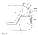
- FIG. 1 the rear end of a schematically represented and overall with 1 designated vehicle, in which between a rear seat back 2 and pivotable tailgate 3, a cargo space 4 is provided, which is down through a trunk floor 5 and is limited at the top by a cover 6.
- This Cover 6 lies on side wall panels 7, 8 and is on these Bearing pins 9, 10 in bearing mounts 11, 12 are pivotally received.
- By Movement of the tailgate 3 around a flap hinge 13 can cover the 6th as a whole or at least one lid-like part by means of drawstrings 14, 15 be raised.
- the cover 6 seals an occupant cell 16 of the vehicle 1 from the cargo space 4.
- the design of this as a case or electrical device Cover 6 is explained in more detail with reference to Figures 2 to 6.
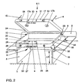
- Figure 2 shows an overall designated 6.1, the essential Elements here are a case lid 17 and a case bottom 18.
- the Bearing pins 9, 10 are integrally formed and can be inserted into the bearing receptacles 11, 12. Further supporting functions are carried out by flange flanges 19 and 20 on the edge can be placed on counter profile edges 21, 22.
- the case bottom 18 is thus clear fixed in position and also opposite the side parts 7, 8 in front of the seat 2 pivotable.
- On the case lid 17 bearing rings 23, 24 are provided are rotatably connected to the bearing pins 9, 10. The width of the bearing rings 23, 24 is dimensioned such that after using the entire cover 6.1 in between Parts 7 and 8 of the case lid 17 is pivotable independently of the case bottom 18.
- the lock can be designed so that, for example Lifting the tailgate 3 either only the case lid 17 alone or the Case lid 17 with the case bottom 18 passed together into a swivel position.
- Locking the case lid 17 and case bottom 18 takes place by means of a transport handle 27, which is in the in the drawing shown rest position is within the contour of the cover 6.1. In this In the rest position, the lock on the case lid 17 is released. By pulling it out According to arrow A, locking hooks 28, 29 can be inserted into locking profiles 30, 31 of the case lid 17 engage and lock the two case parts 17, 18 automatically for transport together.
- the user of the cover 6.1 must be concerned about the security of loss in it So do not actively take care of the stored goods, but get this through the actuation of the transport handle 27, which is necessary for the transport anyway provided automatically. For more details of this latching, see the description refer to Figures 4a and 4b.
- a reset 32 through which the cover 6.1 to the loading edge 33 a allows increased loading height LH.
- a recess 34 is more Seat back 2 assigned.
- the reset 32 may also be limited to a partial area of the case bottom 18, which is in terms of its extent in the vehicle transverse direction on the dimensions more commercially available beverage crates oriented.
- FIG. 3 shows a conceived as a retrofit kit Cover 6.2.
- 117 there is an existing case lid in the vehicle anyway Luggage rack called, on which journals 109 and 110 are integrally formed.
- a storage recess 118 is provided here for the bottom of the case, which extends over bearing shells 123, 124 can be detachably coupled to the luggage rack 117.
- Assembly can be jointly in the bearing receptacles 11, 12 (see also figure 2) can be used.
- As an essential additional feature and independent Solution are assigned to the storage recess 118 power sockets, one of which Low-voltage connection with 35 and an AC mains connection with 36 is designated.
- connection socket 36 is particularly interesting for those applications in which the entire cover 6.2 from the vehicle is removed and, for example, at a campsite or inside a garage a conventional AC network is to be connected.
- a so-called power supply unit or a transformer can also be used in the cover 6.2 (200 - 250V AC / 3-24V DC) can be integrated.
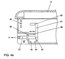
- Transport handle 27 is shown in Figure 4a is a sectional drawing.
- the one in there Transport handle 27 in the rest position is located within a base-side Trough 37 and is by the cooperation of a compression spring 38 and one Stop ring 39 held in this position.
- locking arms 41 are attached, which are formed with a Locking hook 42 can be moved into a recess 43 which is in turn assigned to the case lid 17.
- This locking position is reached if when removing the entire cover 6.1, the transport handle 27 in Direction of arrow A is pulled out against the action of compression spring 38.
- the End position for the transport handle 27 is reached when a clip hook 44 on Locking arm 41 snaps into a clip button 45.
- the one described above Clip connection is designed so that on the one hand the restoring forces from the Compression spring 38 can withstand, but on the other hand relatively light by hand can be suppressed.
- This construction ensures that after the parking from the vehicle 1 storage of the case lid 17 is not from Case bottom 18 can loosen if the entire cover is previously placed upright has been. It is expressly pointed out here that those shown in Figure 4a Connections are purely schematic in nature. The constructive implementation can Individual cases can be carried out very differently.
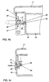
- FIG. 4b An alternative locking concept is shown, for example, in FIG. 4b.
- the Transport handle 27 Rotatably and is by a in the direction of the arrow B
- Prestressed torsion spring 38 'fixed in a rest position, as shown in the drawing can be seen.
- This rest position there is a latch between the case lid 17 and Case bottom 18 only via a clip assembly 46, which is relatively easily solved by hand can be.
- This clip assembly 46 can cover the entire circumference of Case lid 17 and case bottom 18 be distributed and is dimensioned such that, for example even if the cover 6.1 is inclined there is no cargo can cause unwanted opening.
- lock locks can also be provided, as already shown in FIG paragraphs 25 and 26 have been roughly indicated.
- Locking by means of a locking lever 50, which with a in a receiving sleeve 51 guided push button 52 can be actuated against the action of a compression spring 53.
- the Locking lever 50 engages around a locking hook 54, which in turn on Case lid 17 is mounted.
- This drawing is also of a purely schematic nature. It can be used here conventional lock constructions, as they for example from travel suitcases, briefcases or tool cases.
- FIG. 5 shows as a preferred embodiment for a cover 6.3 as Case bottom, a module box 218, which is formed here by partitions 55, 56 in standardized compartments 57 to 59 is divided.
- this Receiving compartments are adapted as on-board equipment items, for example one Recording box 60 for a warning triangle, a first aid kit 61 and a Tool kit 62. Gripping recesses 63 in the partitions 55 and 56 allow a simplified storage and removal of the above Equipment.
- the module box 218 does not necessarily have to be a Emergency case can be designed, but can also be used for other applications become. Insert parts in the form of liquid containers or are conceivable Sorting boxes for a wide variety of applications. As typical transport goods in A wide variety of sports equipment, beverage containers, Flashlights or on-board lamps, hygiene articles (especially for small children), wraps, Children's toys, stationery, magazines or the like.
- such Module box 218 can also be prepared as a standard fastening for audio devices.
- the module box 218 with power connections (see FIG. 2, positions 35 and 36). If necessary, there are also connections for headphones or loudspeaker sockets.
- the module box 218 could then for example, portable cassette recorders or radios that are stored during can be used by rear passengers.
- a device is Consumer electronics even the rear shelf. Its outer contour is vehicle-specific designed so that it covers the storage space between the side parts 7 and 8 can be fitted.
- a clear position fixation can, for example Ensure bearing journals 309 and 310 which can be inserted into the bearing receptacles 11, 12 are. After removal from the vehicle 1, the journals 309, 310 are in accordance with The direction of the arrow can be moved into the contour of the cover 6.4.
- the one shown in Figure 6 Embodiment is a portable combi music device, for example a CD player, includes a cassette deck and a radio part.
- Loudspeakers 64, 65 are either integrated into the device housing or can be used as separate components with it only be loosely connected to operate outside the vehicle if necessary, to be able to be installed away from the actual core device.
- a module concept is also proposed for cover 6.4 in such a way that standardized loudspeaker and music playback devices in vehicle-specific designed basic carrier can be fitted.
- the invention is not based on the exemplary embodiments shown in the drawing limited.
- the different concepts are only intended to indicate with which high variability the invention can be used on vehicles of all kinds can.
Landscapes
- Engineering & Computer Science (AREA)
- Mechanical Engineering (AREA)
- Vehicle Step Arrangements And Article Storage (AREA)
- Rear-View Mirror Devices That Are Mounted On The Exterior Of The Vehicle (AREA)
- Purses, Travelling Bags, Baskets, Or Suitcases (AREA)
- Diaphragms And Bellows (AREA)
- Fittings On The Vehicle Exterior For Carrying Loads, And Devices For Holding Or Mounting Articles (AREA)
Abstract
Description
Die Erfindung betrifft eine Abdeckung für einen Fahrzeugladeraum gemäß dem Oberbegriff des Patentanspruchs 1.The invention relates to a cover for a vehicle hold according to the Preamble of claim 1.
Derartige Abdeckungen sind beispielsweise bekannt aus
der DE-3734774-A1 (B60R 7/04). Die Abdeckung ist als
Hutablage ausgeführt, die das Angebot von Ablagemöglichkeiten im Fahrzeug bei guter
Zugänglichkeit ergänzt.Such covers are known for example from
DE-3734774-A1 (
In der DE 3243802-A1 (B60R 7/04) ist die Abdeckung als eine Hutablage ausgeführt, die sich zwischen den Fondsitzen und der Heckscheibe eines Kraftfahrzeugs erstreckt. In die als Innenverkleidungselement ausgeführte Hutablage ist eine Ablageschale eingesetzt, die durch einen Deckel verschließbar ist. Der Deckel ist dabei materialeinheitlicher Bestandteil der Hutablagenverkleidung. Die Hutablage selbst ist als Auflageteil ausgeführt und deckt die Ablageschale nur mit einem geringen Anteil ihrer Oberfläche ab.In DE 3243802-A1 (B60R 7/04) the cover is designed as a parcel shelf that extends between the rear seats and the rear window of a motor vehicle. In the a shelf is used as the interior shelf element, which can be closed by a lid. The lid is more uniform Part of the parcel shelf trim. The parcel shelf itself is designed as a support part and only covers the storage tray with a small proportion of its surface.
Die DE-4442042-A1 und EP-0556100-B1 (beide B60R 7/02) zeigen jeweils einen als
Stauvorrichtung ausgeführten Behälter, der in einem Bereich im vorderen oberen
Abschnitt des Kofferraums eines Fahrzeuges angebracht ist. Der nach Art einer Huboder
Schwenklade ausgeführte Behälter ist bei geöffneter Kofferraumhaube zugänglich
und kann zur Ablage unterschiedlichster Gegenstände genutzt werden. Die dort gezeigte
Behälteranordnung schränkt die Stauraumhöhe ein, auch wenn der Nachteil durch eine
Stauraumhöheneinstellung zumindest zeitweise eingeschränkt beseitigt werden kann.DE-4442042-A1 and EP-0556100-B1 (both
Die DE 29508382-U1 (B 60 R 7/00) zeigt als Transportbehälter einen stationär unter
einem Fahrzeugdach hängenden Staukasten, der nach seiner Entfernung aus der
Befestigungslage als bewegliche Transportbox nutzbar und wie ein Koffer tragbar
ausgebildet ist. Als bevorzugter Anwendungsbereich dieses Transportbehälters werden
Reisemobile, Caravans, Campingfahrzeuge im allgemeinen, Reisebusse und auch
Flugzeuge betrachtet, insgesamt also sehr großvolumige Fahrzeuge. DE 29508382-U1 (B 60
Die DE 3407299-A1 (B 60 R 11/02) zeigt eine Heckablage, die als Trägerteil für eine fahrzeugindividuell ausgestaltete Lautsprecherbox nutzbar ist.DE 3407299-A1 (B 60 R 11/02) shows a rear shelf that acts as a carrier part for a vehicle-specific loudspeaker box can be used.
Die WO 97/22495 zeigt als Abdeckung für einen Fahrzeugladeraum eine zwischen Fondsitzen und Heckklappe hin- und herbewegbare Rollokonstruktion. Das in unterschiedlichen Raststellungen arretierbare Endstück der Rolloanordnung ist als Ablageschale ausgeführt, die vom Fahrzeuginnenraum oder bei geöffneter Heckklappe auch von einer hinter dem Fahrzeug stehenden Person befüllt werden kann. Es wird damit eine zusätzliche Ablagemöglichkeit geschaffen, die bei derartigen Rollokonstruktionen an sich im Fahrzeug nicht vorhanden ist. Das nutzbare Ablagevolumen ist jedoch sehr gering.WO 97/22495 shows a cover for a vehicle hold Rear seats and tailgate reciprocating roller blind construction. This in different locking positions lockable end piece of the blind arrangement is as Storage tray executed from the vehicle interior or with the tailgate open can also be filled by a person standing behind the vehicle. It will thus an additional storage space created in such roller blind constructions is not actually present in the vehicle. The usable storage volume is however very low.
Der Erfindung liegt die Aufgabe zugrunde, gattungsgemäße Abdeckungen unter Wahrung ihrer Vorteile zu verbessern.The invention has for its object generic covers while preserving improve their benefits.
Diese Aufgabe wird gelöst mit dem Abdeckung gemäß den Merkmalen des Patentanspruchs 1. Die Unteransprüche betreffen besonders zweckmäßige Weiterbildungen der Erfindung.This object is achieved with the cover according to the features of the patent claim 1. The Subclaims relate to particularly expedient further training of the Invention.
Die Erfindung gemäß Patentanspruch 1 sieht wenigstens einen lagever-änderbaren Transportgriff vor, der die Entnahme der Abdeckung aus dem Fahrzeug und auch das Wiedereinsetzen nach Gebrauch außerhalb des Fahrzeugs erleichtert, wobei der Transportgriff bei Bewegung aus seiner Ruhestellung in eine Gebrauchsstellung gleichzeitig den Kofferboden und den Kofferdeckel miteinander verriegelt. Im Falle der Verwendung der erfindungsgemäßen Abdeckung als Koffer wird damit sichergestellt, daß insbesondere bei einem hohen Befüllungsgrad keine versehentliche Öffnung des Koffers und damit ein Herausfallen des Kofferinhaltes eintreten kann. Der Transportgriff kann als weitgehend gestaltfestes Formteil oder auch nach Art eines Streifenbandes ausgeführt sein.The invention according to claim 1 provides at least one position changeable Transport handle in front of which the removal of the cover from the vehicle and also facilitates reinstallation after use outside the vehicle, the transport handle when moving from its rest position into a use position at the same time Case bottom and the case lid locked together. In case of using the Cover according to the invention as a case thus ensures that in particular a high degree of filling no accidental opening of the case and thus one Falling out of the case contents can occur. The transport handle can be considered largely design-resistant molded part or in the manner of a strip tape.
Insbesondere bei Kompaktfahrzeugen sind Abdeckungen gemäß Patentanspruch 14 von
Vorteil. Durch eine zumindest teilweise Rücksetzung und/oder Schräganstellung des
Kofferbodens kann gegenüber herkömmlichen Abdeckungen der Abstand zur Ladekante
des Fahrzeugs vergrößert und damit dessen Beladbarkeit verbessert werden, ohne daß
der Abdeckung selbst nennenswert Staumöglichkeiten genommen werden. Das in diesem
Falle reduzierte Stauvolumen in der Abdeckung ist immer noch ausreichend für die
Unterbringung von Kleinteilen (beispielsweise Werkzeug etc.) oder flachen Gegenständen
(beispielsweise Karten etc.). Diese Variante ist vorteilhaft kombinierbar mit der Lösung
gemäß Anspruch 1.In the case of compact vehicles in particular, covers according to
Die Erfindungsweiterbildung gemäß Anspruch 16 ist für die Nachrüstbarkeit, Handhabung und
paßgenaue bzw. klapperfreie Unterbringung im Fahrzeug von besonderer Bedeutung.
Der lösbare Einsatz mittels Lagerzapfen ist so ausgeführt, daß in Einbaulage der
Kofferdeckel allein zwischen wenigstens einer Öffnungsstellung und einer Schließstellung
betätigbar ist oder der Kofferdeckel gemeinsam mit dem Kofferboden aus der Einbaulage
herausbewegbar ist. Hierdurch wird sichergestellt, daß die Zugänglichkeit des Transportbehälters
sowohl bei innerhalb des Fahrzeugs angeordneter Abdeckung als auch bei
aus dem Fahrzeug herausgenommener Abdeckung gewährleistet ist. Damit kann
außerdem ein und dieselbe Abdeckung zum einen als vom Fahrzeug separierbarer
Transportkoffer und zum anderen als durch eine von Hand oder von der Heckklappe über
Zugbänder verschwenkbare Gepäckraumabdeckung genutzt werden. Mit dieser
Konfiguration kann der Kofferdeckel auch als Innenverkleidungsteil und/oder Fahrzeugzubehörteil
ausgeführt werden. Demgegenüber nimmt der Kofferboden die Funktion einer
Laderaumschottwand. Der Kofferdeckel ist somit ein wesentliches Variationsmerkmal,
durch das im wesentlichen baugleich ausgeführte Abdeckungen zum einen auf das
Fahrzeuginnenraumdesign abgestimmt werden können und zum anderen kundenspezifische
Wünsche nach Zubehörteilen wie Lautsprecherboxen oder dergleichen
erfüllbar sind. Außerdem kann beispielsweise der Kofferboden für verschiedene Ausstattungsvarianten
einer Fahrzeugbaureihe als Standardteil ausgeführt sein, weil er im
normalen Fahrbetrieb des Fahrzeuges in der Regel nicht sichtbar ist.The development of the invention according to
Die erfindungsgemäße Konzeption erlaubt auch die Verwendung von ohnehin schon in Fahrzeugen befindlichen Hutablagen bzw. Gepäckablagen als Kofferdeckel. Zu diesem Zweck sind beispielsweise Kofferböden so ausgeführt, daß diese einerseits in den ursprünglich für die Heckablage eingerichteten Lageraufnahmen der Laderaumwandungen einsetzbar sind und andererseits den bereits vorhandenen Lagerungselementen der Heckablage ihrerseits Lagerelemente zur Verfügung stellen.The concept of the invention also allows the use of already in Vehicle hat racks or luggage racks as a trunk lid. To this Purpose, for example, case bottoms are designed so that on the one hand in the Storage fixtures of the load compartment walls originally set up for the rear shelf can be used and on the other hand the existing storage elements make storage elements available to the rear shelf.
In vorteilhafter Weise kann die erfindungsgemäß ausgeführte Abdeckung in unterschiedlicher Weise vermarktet werden. Vorstellbar ist in einer ersten Variante der Verkauf eines Teilsystems, das im wesentlichen die zum Kofferboden und damit zur Laderaumschottwand gehörenden Funktionen umfaßt. Dieser Kofferboden ist auf die Einbaugegebenheiten einer bestimmten Fahrzeugreihe abgestimmt und kann ohne weiteres als Schublade oder Schwenkklappe in bereits vorhandene Lagerungen eingelegt werden. Der Kunde kann dann das bei ihm vorhandene Heckablagenteil mit dieser Grundausstattung verbinden. Alternativ kann vom Fahrzeughersteller oder Zubehörlieferanten auch ein Komplettsystem angeboten werden, das den Kofferboden und den Kofferdeckel gemeinsam umfaßt. Das Komplettsystem selbst kann bei gleichen Einbaumaßnahmen in unterschiedlichen Nutzversionen angeboten werden. Als Grundversion kann beispielsweise eine als Notfallkoffer ausgeführte Abdeckung bereitgestellt werden, die zumindest zur Aufnahme von Verbandskästen und Warndreiecken hergerichtet ist und gegebenenfalls darüber hinaus auch Bordwerkzeug geordnet bereithält. Ergänzend oder altemativ sind Systeme einsetzbar, die zumindest Teile der Abdeckung nach Art einer Babywickeltasche, eines Picknickkorbes, eines Campingsets, eines Hobbygerätekoffers oder ähnliches mehr ermöglichen. Insbesondere bei Fahrzeugen, die bereits für Verbandskästen und Warndreiecke eine geeignete Unterbringungsmöglichkeit bereithalten, können hier auf ausgesuchte Zielgruppen zugeschnittene Transportbehälter angeboten werden.Advantageously, the cover designed according to the invention in marketed in different ways. In a first variant, the Sale of a subsystem that is essentially the bottom of the case and thus the Contains bulkhead functions. This case bottom is on the Installation conditions of a certain vehicle series matched and can be without further inserted as a drawer or swivel flap in existing storage become. The customer can then use the existing rear shelf part with this Connect basic equipment. Alternatively, from the vehicle manufacturer or accessories supplier also a complete system can be offered that the case bottom and Covered trunk together. The complete system itself can do the same installation are offered in different user versions. As a basic version For example, a cover designed as an emergency case can be provided, which is at least prepared to hold first aid kits and warning triangles and if necessary, also has on-board tools in order. Complementary or Alternatively, systems can be used that cover at least parts of the cover in the manner of a Baby changing bag, a picnic basket, a camping set, a hobby case or something similar. Especially for vehicles that are already for First aid kits and warning triangles have suitable accommodation available, can transport containers tailored to selected target groups Tobe offered.
Von herausgehobener Bedeutung ist auch die Erfindungsweiterbildung gemäß Anspruch 22.
Zur Vermeidung
eines sogenannten Kabelsalates im Laderaum und/oder in der Insassenzelle sind -
vorzugsweise genormte und/oder standardisierte - Anschlußmöglichkeiten für elektrischen
Strom dem Kofferdeckel und/oder dem Kofferboden zugeordnet.The further development of the invention according to
Als Weiterbildung der Erfindung ist gemäß Anspruch 23 eine Nutzbarkeit der Abdeckung als Ton- und/oder Bildwiedergabegerät gleichermaßen innerhalb und außerhalb des Fahrzeugs vorgesehen. Abweichend von der in der DE 3407299-A1 gezeigten Lösung ist das elektronische Gerät also nicht auf der Heckablage befestigbar, sondern ist die Heckablage selbst. Insbesondere bei einer Ausführung der Abdeckung als Campingset kann das Elektrogerät auch als ein flach bauender Heizplatten-Kleinherd ausgeführt sein.As a further development of the invention is usability of the cover as a sound and / or image display device equally inside and outside the vehicle intended. This is different from the solution shown in DE 3407299-A1 electronic device can not be attached to the rear shelf, but is the Rear shelf itself. Especially when the cover is designed as a camping set the electrical appliance can also be designed as a flat heating plate small stove.
Die Erfindung liefert positive Beiträge insbesondere für die Nutzbarkeit der Ablage auch außerhalb des Fahrzeugs, ohne das Einbußen für die Verwendung im Innenraum des Fahrzeugs hingenommen werden müssen.The invention makes positive contributions, in particular for Usability of the storage outside of the vehicle, without sacrificing the Use in the interior of the vehicle must be accepted.
Weitere Vorteile der Erfindung ergeben sich aus den Merkmalen der jeweiligen Unteransprüche.Further advantages of the invention result from the features of respective subclaims.
Vorteilhafte Ausführungsbeispiele der Erfindung sind in der Zeichnung dargestellt. Es zeigt
- Figur 1:
- das bevorzugte Anwendungsgebiet für die erfindungsgemäße Abdeckung,
- Figur 2:
- in einer perspektivischen Darstellung ein erstes Ausführungsbeispiel,
- Figur 3:
- in einer vergleichbaren Ansicht ein zweites Ausführungsbeispiel,
- Figur 4a:
- eine erste Variante für eine Kombination aus Transportgriff und Transportsicherung,
- Figur 4b:
- eine zweite Variante für eine Kombination aus Transportgriff und Transportsicherung,
- Figur 4c:
- schematisch ein ergänzender Verschluß zur Arretierung des Kofferdeckels an dem Kofferboden,
- Figur 5:
- eine als Musikgerät ausgeführte Abdeckung,
- Figur 6:
- einen Kofferboden für eine als Notfallkoffer ausgebildete Abdeckung.
- Figure 1:
- the preferred field of application for the cover according to the invention,
- Figure 2:
- a perspective view of a first embodiment,
- Figure 3:
- a second embodiment in a comparable view,
- Figure 4a:
- a first variant for a combination of transport handle and transport lock,
- Figure 4b:
- a second variant for a combination of transport handle and transport lock,
- Figure 4c:
- schematically a supplementary closure for locking the case lid on the case bottom,
- Figure 5:
- a cover designed as a music device,
- Figure 6:
- a case bottom for a cover designed as an emergency case.
Man erkennt in Figur 1 die Heckpartie eines schematisch dargestellten und insgesamt mit
1 bezeichneten Fahrzeuges, bei dem zwischen einer Fondsitzlehne 2 und einer
verschwenkbaren Heckklappe 3 ein Laderaum 4 vorgesehen ist, der nach unten durch
einen Kofferrraumboden 5 und nach oben durch eine Abdeckung 6 begrenzt ist. Diese
Abdeckung 6 liegt auf Seitenwandverkleidungen 7, 8 auf und ist an diesen über
Lagerzapfen 9, 10 in Lageraufnahmen 11, 12 schwenkbeweglich aufgenommen. Durch
Bewegung der Heckklappe 3 um ein Klappenscharnier 13 kann die Addeckung 6
insgesamt oder wenigstens ein deckelartig ausgeführtes Teil durch Zugbänder 14, 15
angehoben werden. Die Abdeckung 6 schottet eine Insassenzelle 16 des Fahrzeugs 1
von dem Laderaum 4 ab. Die Gestaltung dieser als Koffer oder Elektrogerät ausgeführten
Abdeckung 6 wird im Detail anhand der Figuren 2 bis 6 näher erläutert.One can see in Figure 1 the rear end of a schematically represented and overall with
1 designated vehicle, in which between a rear seat back 2 and
Figur 2 zeigt eine insgesamt mit 6.1 bezeichnete Abdeckung, deren wesentliche
Elemente hier ein Kofferdeckel 17 und ein Kofferboden 18 sind. An letzterem sind die
Lagerzapfen 9, 10 integral angeformt und in die Lageraufnahmen 11, 12 einsetzbar.
Weitere Tragfunktionen übernehmen randseitig abgestellte Anlageflansche 19 und 20, die
auf Gegenprofilkanten 21, 22 auflegbar sind. Damit ist der Kofferboden 18 eindeutig
lagefixiert und darüber hinaus auch gegenüber den Seitenteilen 7, 8 vor der Sitzbank 2
verschwenkbar. Am Kofferdeckel 17 sind Lagerringe 23, 24 vorgesehen, die
drehbeweglich mit den Lagerzapfen 9, 10 verbunden sind. Die Breite der Lagerringe 23,
24 ist so bemessen, daß nach Einsatz der gesamten Abdeckung 6.1 zwischen dieser in
Teile 7 und 8 der Kofferdeckel 17 unabhängig vom Kofferboden 18 schwenkbeweglich ist.
Durch unterschiedliche Arretiermechanismen kann dafür gesorgt werden, daß der
Kofferdeckel 17 und der Kofferboden 18 lösbar miteinander verbunden sind. Je nach
Kundenwunsch kann die Arretierung dabei so ausgelegt sein, daß beispielsweise beim
Anheben der Heckklappe 3 entweder nur der Kofferdeckel 17 allein oder aber der
Kofferdeckel 17 mit dem Kofferboden 18 zusammen in eine Schwenkstellung übergebt.Figure 2 shows an overall designated 6.1, the essential
Elements here are a
Die Arretierung von Kofferdeckel 17 und Kofferboden 18
erfolgt mittels eines Transportgriffes 27, der sich bei der in der Zeichnung
dargestellten Ruhestellung innerhalb der Kontur der Abdeckung 6.1 befindet. In dieser
Ruhestellung ist die Arretierung zum Kofferdeckel 17 aufgehoben. Durch Herausziehen
gemäß Pfeil A können Rasthaken 28, 29 in Rastprofile 30, 31 des Kofferdeckels 17
eingreifen und verriegeln so die beiden Kofferteile 17, 18 für den Transport selbsttätig
miteinander. Der Nutzer der Abdeckung 6.1 muß sich um die Verliersicherheit des darin
untergebrachten Transportgutes also nicht aktiv kümmern, sondern bekommt dies durch
die für den Transport ohnehin notwendige Betätigung des Transportgriffes 27 gleichsam
selbsttätig bereitgestellt. Zu näheren Details dieser Verrastung wird auf die Beschreibung
zu den Figuren 4a und 4b verwiesen.Locking the
Von besonderer Bedeutung bei dem in der Figur 2 dargestellten Ausführungsbeispiel ist
auch eine Rücksetzung 32, durch die die Abdeckung 6.1 zur Ladekante 33 eine
vergrößerte Ladehöhe LH zuläßt. Demgegenüber ist eine Vertiefung 34 mehr der
Sitzlehne 2 zugeordnet. Für die Beladung von sperrigen Ladegütern (beispielsweise
Getränkekisten) ist dieser Bereich weniger relevant. Gegebenenfalls kann die Rücksetzung
32 auch auf einen Teilbereich des Kofferbodens 18 beschränkt sein, der sich
hinsichtlich seiner Erstreckung in Fahrzeugquerrichtung an den Abmessungen handelsüblicher
getränkekisten orientiert. Oberhalb der vertiefung 34 sind hier noch Klemmschelien
17a, 17b am Kofferdeckel 17 angeformt oder befestigt, um beispielsweise einen
hier nicht gezeigten Regenschirm lagefixiert unterbringen zu können.Of particular importance in the embodiment shown in Figure 2
also a
Das in Figur 3 dargestellte Ausführungsbeispiel zeigt eine als Nachrüstsatz konzipierte
Abdeckung 6.2. Mit 117 ist als Kofferdeckel eine ohnehin im Fahrzeug vorhandene
Gepäckablage bezeichnet, an der Lagerzapfen 109 und 110 angeformt sind. Als
Kofferboden ist hier eine Ablagemulde 118 vorgesehen, die über Lagerschalen 123, 124
lösbar mit der Gepäckablage 117 gekoppelt werden kann. Der auf diese Weise erzeugte
Zusammenbau kann gemeinsam in die Lageraufnahmen 11, 12 (siehe hierzu auch Figur
2) eingesetzt werden. Als wesentliches Zusatzausstattungsmerkmal und eigenständige
Lösung sind der Ablagemulde 118 Stromanschlußbuchsen zugeordnet, von denen ein
Niedervoltanschluß mit 35 und ein Wechselstrom-Netzanschluß mit 36 bezeichnet ist.
Diese Buchsen sind über hier nicht weiter dargestellte Leitungssysteme mit dem Bordnetz
des Fahrzeugs verbindbar. Insbesondere die Anschlußbuchse 36 ist interessant für
solche Anwendungsfälle, bei denen die gesamte Abdeckung 6.2 aus dem Fahrzeug
entfernt wird und beispielsweise auf einem Campingplatz oder innerhalb einer Garage an
ein konventionelles Wechselspannungsnetz angeschlossen werden soll. Zu diesem
Zweck kann in die Abdeckung 6.2 auch ein sogenanntes Netzteil bzw. ein Transformator
(200 - 250V Wechselstrom / 3-24V Gleichstrom) integriert sein.The embodiment shown in Figure 3 shows a conceived as a retrofit kit
Cover 6.2. At 117, there is an existing case lid in the vehicle anyway
Luggage rack called, on which
Zur näheren Erläuterung der Verriegelungsfunktion des in Figur 2 dargestellten
Transportgriffes 27 ist in Figur 4a eine Schnittzeichnung dargestellt. Der dort in der
Ruhestellung befindliche Transportgriff 27 befindet sich innerhalb einer bodenseitigen
Mulde 37 und wird durch das Zusammenwirken einer Druckfeder 38 und eines
Anschlagringes 39 in dieser Position gehalten. An den innenraumseitigen Enden 40 des
Transportgriffes 27 sind Verriegelungsarme 41 befestigt, die mit einem angeformten
Verriegelungshaken 42 in eine Rastausnehmung 43 hineinbewegt werden können, die
ihrerseits dem Kofferdeckel 17 zugeordnet ist. Diese Verrastungsstellung wird erreicht,
wenn beim Herausnehmen der gesamten Abdeckung 6.1 der Transportgriff 27 in
Pfeilrichtung A gegen die Wirkung der Druckfeder 38 herausgezogen wird. Die
Endposition für den Transportgriff 27 ist dann erreicht, wenn ein Clipshaken 44 am
Verriegelungsarm 41 in einen Clipsknopf 45 einrastet. Die vorstehend beschriebene
Clipsverbindung ist so ausgelegt, daß sie einerseits den Rückstellkräften aus der
Druckfeder 38 standhalten kann, andererseits aber von Handkraft relativ leicht
überdrückbar ist. Mit dieser Konstruktion ist gewährleistet, daß nach dem Abstellen der
aus dem Fahrzeug 1 entnommenen Ablage der Kofferdeckel 17 sich nicht vom
Kofferboden 18 lösen kann, wenn die gesamte Abdeckung zuvor hochkant abgelegt
wurde. Es wird hier ausdrücklich darauf verwiesen, daß die in Figur 4a gezeigten
Zusammenhänge rein schematischer Natur sind. Die konstruktive Umsetzung kann im
Einzelfall höchst unterschiedlich ausgeführt sein.For a more detailed explanation of the locking function of the shown in Figure 2
Transport handle 27 is shown in Figure 4a is a sectional drawing. The one in there
Transport handle 27 in the rest position is located within a base-
Ein alternatives Verriegelungskonzept zeigt beispielsweise Figur 4b. Dort ist der
Transportgriff 27' drehgelagert und wird durch eine in Richtung des Drehpfeiles B
vorgespannte Drehfeder 38' in einer Ruhestellung fixiert, wie sie aus der Zeichnung
ersichtlich ist. In dieser Ruhestellung folgt eine Verrastung zwischen Kofferdeckel 17 und
Kofferboden 18 lediglich über eine Clipsanordnung 46, die von Hand relativ leicht gelöst
werden kann. Diese Clipsanordnung 46 kann auf dem gesamten Umfang von
Kofferdeckel 17 und Kofferboden 18 verteilt sein und ist so bemessen, daß beispielsweise
auch bei schrägstehender Abdeckung 6.1 darin untergebrachtes Ladegut keine
ungewolite Öffnung herbeiführen kann. Um aber bei einem Gebrauch der Abdeckung 6.1
als tragbaren Koffer eine eindeutige Verriegelung sicherstellen zu können, ist hier an dem
Transportgriff 27' ein Verriegelungshebel 42' angeformt, der bei einer gegen die
Rückstellkraft der Drehfeder 38' erfolgenden Verschwenkung gemäß Pfeilrichtung C auf
einer an dem Kofferdeckel 17 angeformten Haltenasen 47 zur Anlage gebracht wird. Die
Geometrie eines Hebelendes 48 ist so ausgeführt, daß für die mit Strichlinien
angedeutete Verrastungsposition in einer Rastmulde 49 ebenfalls eine von Handkraft
leicht überdrückbare Verrastung sichergestellt ist, die aber der von der Drehfeder 38'
ausgeübten Rückstellkraft standhält.An alternative locking concept is shown, for example, in FIG. 4b. There is the
Transport handle 27 'rotatably and is by a in the direction of the arrow B
Prestressed torsion spring 38 'fixed in a rest position, as shown in the drawing
can be seen. In this rest position there is a latch between the
Ergänzend zu den vorstehend beschriebenen Transportgriffarretierungen
können auch Schloßverriegelungen vorgesehen werden, wie sie bereits in der Figur 2 mit
den Ziffern 25 und 26 grob angedeutet worden sind. Vorstellbar ist beispielsweise eine
Arretierung (siehe Figur 4c) mittels eines Verriegelungshebels 50, der mit einem in einer Aufnahmehülse
51 geführten Druckknopf 52 gegen die Wirkung einer Druckfeder 53 betätigbar ist. Der
Verriegelungshebel 50 umgreift einen Verriegelungshaken 54, der seinerseits am
Kofferdeckel 17 gelagert ist. Auch diese Zeichnung ist rein schematischer Natur. Es
können hier konventionelle Schloßkonstruktionen eingesetzt werden, wie sie
beispielsweise von Reisekoffern, Aktenkoffern oder Werkzeugkoffern bekannt sind.In addition to the transport handle locks described above
lock locks can also be provided, as already shown in
Figur 5 zeigt als bevorzugtes Ausführungsbeispiel für eine Abdeckung 6.3 als
Kofferboden eine Modulkiste 218, die durch hier eingeformte Trennwände 55, 56 in
standardisierte Aufnahmefächer 57 bis 59 unterteilt ist. An die Konturen diese
Aufnahmefächer angepaßt sind als Bordausrüstungsgegenstände beispielsweise eine
Aufnahmebox 60 für ein Warndreieck, ein Verbandskasten 61 sowie ein
Bordwerkzeugsatz 62. Greifaussparungen 63 in den Trennwänden 55 und 56
ermöglichen eine vereinfachte Ablage und Entnahme der vorstehend beschriebenen
Ausrüstungsgegenstände. Die Modulkiste 218 muß aber nicht zwangsläufig nur als
Notfallkoffer konzipiert sein, sondern kann auch für andere Anwendungen genutzt
werden. Vorstellbar sind Einsatzteile nach Art von Flüssigkeitsbehältern oder
Sortierkästen für unterschiedlichste Anwendungsfälle. Als typische Transportgüter in
Betracht gezogen werden können unterschiedlichste Sportgeräte, Getränkebehältnisse,
Taschen- bzw. Bordlampen, Hygieneartikel (insbesondere für Kleinkinder), Wickeltücher,
Kinderspielzeug, Schreibwaren, Zeitschriften oder dergleichen mehr.Figure 5 shows as a preferred embodiment for a cover 6.3 as
Case bottom, a
Gemäß einer besonders vorteilhaften Weiterbildung der Erfindung kann eine solche
Modulkiste 218 auch als Standardbefestigung für Audiogeräte hergerichtet sein. Zu
diesem Zweck ist die Modulkiste 218 mit Stromanschlüssen (siehe Figur 2, Positionen 35
und 36) herzurichten. Gegebenenfalls sind ergänzend auch Anschlüsse für Kopfhörer
oder Lautsprecherbuchsen vorzusehen. In eine solche Modulkiste 218 könnten dann
beispielsweise tragbare Cassettenrecorder oder Radios abgelegt werden, die während
der Fahrt von Fondinsassen benutzbar sind.According to a particularly advantageous development of the invention,
Bei einer anderen Erfindungsweiterbildung ist - wie in Figur 6 dargestellt - ein Gerät der
Unterhaltungselektronik selbst die Heckablage. Dessen Außenkontur ist fahrzeugindividueli
so gestaltet, daß es zur Stauraumabdeckung zwischen die Seitenteile 7 und 8
eingepaßt werden kann. Eine eindeutige Lagefixierung können beispielsweise
Lagerzapfen 309 und 310 sicherstellen, die in die Lageraufnahmen 11, 12 einsteckbar
sind. Nach Entfernung aus dem Fahrzeug 1 sind die Lagerzapfen 309, 310 gemäß
Pfeilrichtung in die Kontur der Abdeckung 6.4 hineinverlegbar. Das in Figur 6 gezeigte
Ausführungsbeispiel ist ein tragbares Kombi-Musikgerät, das beispielsweise einen CD-Player,
ein Cassetten-Deck und ein Radioteil umfaßt. Lautsprecherboxen 64, 65 sind
entweder in das Gerätegehäuse integriert oder können als separate Bauteile mit diesem
nur lose verbunden sein, um dann für einen Betrieb außerhalb des Fahrzeugs
gegebenenfalls auch vom eigentlichen Kemgerät entfernt aufgestellt werden zu können.
Auch für die Abdeckung 6.4 wird ein Modulkonzept dergestalt vorgeschlagen, daß
standardisierte Lautsprecher- und Musikwiedergabegeräte in fahrzeugindividuell
gestaltete Grundträger eingepaßt werden.In another development of the invention, as shown in FIG. 6, a device is
Consumer electronics even the rear shelf. Its outer contour is vehicle-specific
designed so that it covers the storage space between the
Die Erfindung ist nicht auf die in der Zeichnung dargestellten Ausführungsbeispiele beschränkt. Die unterschiedlichen Konzepte sollen hier lediglich andeuten, mit welch hoher Variabilität die Erfindung an Fahrzeugen unterschiedlichster Art verwendet werden kann.The invention is not based on the exemplary embodiments shown in the drawing limited. The different concepts are only intended to indicate with which high variability the invention can be used on vehicles of all kinds can.
Claims (28)
- Cover (6.1-6.4), designed as a suitcase-like hollow body, for a motor vehicle luggage compartment (4), comprising at least one transport container which is an integral part of the hollow body and is designed to receive luggage between at least one suitcase lid (17) and a suitcase bottom (18), characterized in that at least one carrying handle (27, 27'), the position of which can be varied, is provided on the at least one suitcase lid (17) and/or on the suitcase bottom (18) and in that the handle is so configured that, by moving the carrying handle (27, 27'), the suitcase lid (17) can be locked relative to the suitcase bottom (18).
- Cover according to Claim 1, characterized in that the at least one carrying handle (27, 27') is retained in a position of rest by at least one spring element (38, 38') and is adjustable, against the restoring force of the spring element (38, 38'), into a position of use which makes it possible for the cover (6.1-6.4) to be handled in the manner of a suitcase.
- Cover according to Claim 1 or 2, characterized in that, in the position of rest, the suitcase lid (17) can be pivoted relative to the suitcase bottom (18) and in that, by moving the carrying handle (27, 27') into the position of use, the suitcase lid (17) is locked relative to the suitcase bottom (18).
- Cover according to at least one of Claims 1 to 3, characterized in that the carrying handle (27, 27') is locked in the position of use in a latching device (44 and 45; 48 and 49) which resists the restoring force of the at least one spring element (38, 38') but can be forced over manually.
- Cover according to at least one of Claims 1 to 4, characterized in that the suitcase lid (17) or the suitcase bottom (18) possesses at least one storage compartment or a storage compartment is formed jointly by the suitcase lid (17) and the suitcase bottom (18).
- Cover according to Claim 5, characterized in that the storage compartment is designed to receive a warning triangle or a first-aid chest or a tool kit or a tool kit container or a reserve petrol can or an umbrella or sporting equipment or a drinks container or a stationery container or a sorting box or a pocket torch or flashlight or an audio appliance or sanitary articles, especially for small children, or a changing kit for babies or a child's toy or at least one battery or at least one accumulator or a power pack/transformer.
- Cover according to at least one of Claims 1 to 6, characterized in that the suitcase lid (17) is formed as the top of the cover (6.1-6.3) in the manner of an internal lining and/or internal trim part.
- Cover according to at least one of Claims 1 to 7, characterized in that the suitcase bottom (18) is formed as an underside in the manner of a luggage space partition.
- Cover according to at least one of Claims 1 to 8, characterized in that it is formed in the manner of a rear shelf or parcel shelf.
- Cover according to at least one of Claims 1 to 9, characterized in that the suitcase lid (17) is formed by a rear shelf (117) which is in any case present in the vehicle and is designed to be jointly accommodated in the vehicle (1) together with a suitcase bottom (118) adapted thereto.
- Cover according to at least one of Claims 1 to 10, characterized in that the detachable use of the suitcase lid (17) and/or of the suitcase bottom (18) is additionally ensured by an edge section.
- Cover according to at least one of Claims 1 to 11, characterized in that the suitcase lid (17) can be locked relative to the suitcase bottom (18) by means of at least one lock arrangement (25, 26).
- Cover according to at least one of Claims 1 to 12, characterized in that the suitcase bottom (18) is configured as a standard component into which at least one storage compartment or a set of storage compartments can be introduced, this storage compartment or set of storage compartments being formed with at least one standard connection configuration adapted to the standard component.
- Cover according to one of Claims 1 to 13, characterized in that the suitcase bottom (18) comprises, in the bottom region, a recessed portion (32) permitting relatively large luggage to be accommodated in the vehicle luggage compartment (4).
- Cover according to Claim 14, characterized in that the recess portion (32) is designed, in terms of its extent in the transverse direction of the vehicle, to match commercially available beverage crates.
- Cover according to one of Claims 1 to 15, characterized in that detachable use in the vehicle (1) is ensured by bearing pins (9, 10).
- Cover according to Claim 16, characterized in that it can be adjusted by means of the bearing pins (109, 110 or 309, 310) between a bearing position and a position of rest.
- Cover according to Claim 16 or 17, characterized in that the bearing pins are designed to be mounted on the vehicle on one end and to be mounted between the suitcase lid (17) and suitcase bottom (18) at the other end.
- Cover according to Claim 16, characterized in that retaining means are provided on the suitcase lid (17) and/or on the suitcase bottom (18) and are designed to be connected to tensioning means (14, 15) which are or can be fixed to a vehicle tail gate (3).
- Cover according to Claim 16, characterized in that the suitcase lid (17) can be locked in various pivoting positions relative to the suitcase bottom (18).
- Cover according to at least one of Claims 16 to 20, characterized in that, in the installed position, either the suitcase lid (17) alone can be moved into an open or closed position or the suitcase lid (17) can be moved out of the installed position jointly with the suitcase bottom (18).
- Cover according to one of Claims 1 to 16, characterized in that the suitcase lid (17) and/or the suitcase bottom (18) comprises at least one connection for electrical current.
- Cover according to one of Claims 1 to 22, characterized in that the hollow body forms at least part of the housing for an electrical appliance.
- Cover according to Claim 22 or 23, characterized in that the connection is configured as a low-voltage socket.
- Cover according to Claim 22 or 23, characterized in that the connection is configured as a 200-250 volt alternating current connection.
- Cover according to at least one of Claims 22 to 25, characterized in that the electrical appliance is in the form of a portable sound and/or vision playback appliance.
- Cover according to at least one of Claims 22 to 26, characterized in that the sound and/or vision playback appliance is disposed between two loudspeaker boxes.
- Cover according to at least one of Claims 22 to 27, characterized in that an arrangement of loudspeaker boxes and storage compartment is provided, in a manner such that the loudspeaker boxes enclose the at least one storage compartment between them.
Priority Applications (1)
| Application Number | Priority Date | Filing Date | Title |
|---|---|---|---|
| EP02018052A EP1258396B1 (en) | 1997-09-20 | 1998-09-18 | Covering for a vehicle load compartment |
Applications Claiming Priority (3)
| Application Number | Priority Date | Filing Date | Title |
|---|---|---|---|
| DE19741628 | 1997-09-20 | ||
| DE19741628A DE19741628A1 (en) | 1997-09-20 | 1997-09-20 | Cover for vehicle baggage space e.g. cars, caravans, aircraft |
| PCT/EP1998/005967 WO1999015361A1 (en) | 1997-09-20 | 1998-09-18 | Covering element for a vehicle loading compartment |
Related Child Applications (1)
| Application Number | Title | Priority Date | Filing Date |
|---|---|---|---|
| EP02018052.7 Division-Into | 2002-08-13 |
Publications (2)
| Publication Number | Publication Date |
|---|---|
| EP1012002A1 EP1012002A1 (en) | 2000-06-28 |
| EP1012002B1 true EP1012002B1 (en) | 2003-03-26 |
Family
ID=7843119
Family Applications (2)
| Application Number | Title | Priority Date | Filing Date |
|---|---|---|---|
| EP02018052A Expired - Lifetime EP1258396B1 (en) | 1997-09-20 | 1998-09-18 | Covering for a vehicle load compartment |
| EP98952602A Expired - Lifetime EP1012002B1 (en) | 1997-09-20 | 1998-09-18 | Covering element for a vehicle loading compartment |
Family Applications Before (1)
| Application Number | Title | Priority Date | Filing Date |
|---|---|---|---|
| EP02018052A Expired - Lifetime EP1258396B1 (en) | 1997-09-20 | 1998-09-18 | Covering for a vehicle load compartment |
Country Status (4)
| Country | Link |
|---|---|
| EP (2) | EP1258396B1 (en) |
| AT (2) | ATE283778T1 (en) |
| DE (3) | DE19741628A1 (en) |
| WO (1) | WO1999015361A1 (en) |
Cited By (2)
| Publication number | Priority date | Publication date | Assignee | Title |
|---|---|---|---|---|
| DE102010004549A1 (en) | 2010-01-14 | 2011-07-21 | Dr. Ing. h.c. F. Porsche Aktiengesellschaft, 70435 | Battery system and motor vehicle |
| DE102017210120A1 (en) | 2017-06-16 | 2018-12-20 | Ford Global Technologies, Llc | Load compartment cover and motor vehicle |
Families Citing this family (20)
| Publication number | Priority date | Publication date | Assignee | Title |
|---|---|---|---|---|
| DE10030657A1 (en) * | 2000-06-23 | 2002-01-03 | Volkswagen Ag | Cladding element for boot (trunk) and boot lid or tailgate is fitted with devices to receive small objects |
| CA2441558C (en) * | 2001-03-26 | 2010-02-02 | Magna International Inc. | Mid structural module |
| DE10244768B4 (en) * | 2002-09-26 | 2013-11-07 | Volkswagen Ag | Device for holding objects in a motor vehicle trunk |
| DE10321837B4 (en) * | 2003-05-15 | 2014-03-27 | Volkswagen Ag | Center console for a vehicle |
| DE10341851A1 (en) * | 2003-09-09 | 2005-03-31 | Opel Eisenach Gmbh | Container to be used for accommodation of wound-up cover for loading area of estate version of car |
| DE102004020930B4 (en) * | 2004-04-28 | 2007-05-24 | Adam Opel Ag | Tray in the interior of a motor vehicle |
| EP1717104A1 (en) * | 2005-04-28 | 2006-11-02 | Grupo Antolin Ingenieria, S.A. | Package tray for vehicles |
| DE102007002409B3 (en) * | 2007-01-17 | 2008-06-26 | Ford Global Technologies, LLC, Dearborn | Console e.g. center console, mounting unit for e.g. car, has compartment with fixing units provided in area of upper edge, where fixing units hold electronic devices e.g. personal digital assistant, in position in compartment |
| DE102009058437B4 (en) | 2009-12-16 | 2011-11-10 | Airbus Operations Gmbh | Storage system for an emergency equipment |
| US9381798B2 (en) | 2010-01-14 | 2016-07-05 | Dr. Ing. H.C.F. Porsche Aktiengesellschaft | Battery system and motor vehicle |
| DE102010050452B4 (en) * | 2010-10-26 | 2012-10-18 | Bos Gmbh & Co. Kg | Cargo space for a motor vehicle and storage container |
| DE102012012038A1 (en) | 2012-06-19 | 2013-12-19 | Volkswagen Aktiengesellschaft | Storage device for luggage compartment of vehicle, and for use with case, has receiving container that is a case, which is removable from supporting element, where inner space of case is to be closed completely by case walls |
| DE102013106676A1 (en) * | 2013-06-26 | 2014-12-31 | Dr. Ing. H.C. F. Porsche Ag | Motor vehicle, in particular electric vehicle |
| US9440590B1 (en) * | 2015-04-09 | 2016-09-13 | Ford Global Technologies, Llc | Cargo shade storage pocket with hidden storage |
| DE102015206947A1 (en) | 2015-04-17 | 2016-10-20 | Ford Global Technologies, Llc | Cover for a vehicle boot and vehicle |
| DE102016203807B4 (en) | 2015-04-17 | 2025-12-31 | Ford Global Technologies, Llc | Cover for a rear vehicle cargo area and vehicle |
| FR3080592B1 (en) * | 2018-04-27 | 2020-09-18 | Psa Automobiles Sa | REMOVABLE STORAGE DEVICE FIXED ON THE GUIDE TUBES OF THE SEAT HEADREST OF THE VEHICLE AND CORRESPONDING VEHICLE. |
| US12409784B2 (en) | 2023-04-06 | 2025-09-09 | Ford Global Technologies, Llc | Vehicle having load floor holder |
| WO2025125693A1 (en) * | 2023-12-14 | 2025-06-19 | Brose Fahrzeugteile Se & Co. Kommanditgesellschaft, Bamberg | Modular assembly for a storage space of a motor vehicle, and mounting method |
| DE102024202328A1 (en) * | 2024-03-12 | 2025-09-18 | Volkswagen Aktiengesellschaft | Loudspeaker system for sounding the interior of a vehicle |
Family Cites Families (16)
| Publication number | Priority date | Publication date | Assignee | Title |
|---|---|---|---|---|
| US4501013A (en) * | 1979-09-18 | 1985-02-19 | Olympus Optical Co., Ltd. | Car stereo set |
| DE3243802C2 (en) | 1982-11-26 | 1986-06-05 | Daimler-Benz Ag, 7000 Stuttgart | Storage tray with lid, in particular for holding bandages |
| DE3407299A1 (en) | 1984-02-29 | 1985-08-29 | SK Elektronik GmbH, 3500 Kassel | Loudspeaker box for passenger cars with rear parcel shelf |
| DE3734774A1 (en) | 1987-10-14 | 1988-05-26 | Borgwardt Renate | Additional boot space (car safe) for estate cars or similar motor vehicles instead of the so-called rear window shelf |
| ES2017342A6 (en) * | 1989-11-13 | 1991-01-16 | Gonzalez Miruri Alberto | Device for concealing objects in automobiles. |
| FR2687104B1 (en) * | 1992-02-11 | 1994-03-25 | Renault Regie Nale Usines | IMPROVEMENT IN LUGGAGE COMPARTMENTS OF MOTOR VEHICLES. |
| DE9210854U1 (en) * | 1992-08-13 | 1992-10-29 | Schroll, Stefan, Dipl.-Ing. (FH), 8221 Nußdorf | Holding device on the parcel shelf in passenger cars |
| US5324089A (en) * | 1992-08-31 | 1994-06-28 | Schlachter Bradley S | Convertible security enclosure for open deck vehicle |
| JPH07251684A (en) * | 1994-03-14 | 1995-10-03 | Alpine Electron Inc | Removable electronic equipment |
| JPH07251685A (en) * | 1994-03-14 | 1995-10-03 | Alpine Electron Inc | Removable electronic equipment |
| US5564768A (en) * | 1994-07-20 | 1996-10-15 | Saffold; David J. | Portable security trunk for utility vehicles and trucks |
| DE4442042A1 (en) * | 1994-11-25 | 1996-05-30 | Naeher Georg Gmbh | Trunk stowing device |
| DE29508382U1 (en) | 1995-05-19 | 1996-09-19 | Zeppelin Mobile Systeme GmbH, 77656 Offenburg | Storage box for storing and transporting objects |
| DE29514388U1 (en) | 1995-09-07 | 1997-01-09 | Buchhalter, Thomas, 53859 Niederkassel | Storage compartment |
| US5685592A (en) | 1995-12-21 | 1997-11-11 | United Technologies Automotive, Inc. | Cargo compartment cover and item support assembly |
| FR2743035B1 (en) * | 1995-12-29 | 1998-01-23 | Renault | ARRANGEMENT OF AN AUXILIARY TRUNK IN A MOTOR VEHICLE |
-
1997
- 1997-09-20 DE DE19741628A patent/DE19741628A1/en not_active Withdrawn
-
1998
- 1998-09-18 WO PCT/EP1998/005967 patent/WO1999015361A1/en not_active Ceased
- 1998-09-18 EP EP02018052A patent/EP1258396B1/en not_active Expired - Lifetime
- 1998-09-18 EP EP98952602A patent/EP1012002B1/en not_active Expired - Lifetime
- 1998-09-18 DE DE59807668T patent/DE59807668D1/en not_active Expired - Fee Related
- 1998-09-18 DE DE59812341T patent/DE59812341D1/en not_active Expired - Lifetime
- 1998-09-18 AT AT02018052T patent/ATE283778T1/en not_active IP Right Cessation
- 1998-09-18 AT AT98952602T patent/ATE235387T1/en not_active IP Right Cessation
Cited By (5)
| Publication number | Priority date | Publication date | Assignee | Title |
|---|---|---|---|---|
| DE102010004549A1 (en) | 2010-01-14 | 2011-07-21 | Dr. Ing. h.c. F. Porsche Aktiengesellschaft, 70435 | Battery system and motor vehicle |
| DE102010004549B4 (en) | 2010-01-14 | 2020-06-18 | Dr. Ing. H.C. F. Porsche Aktiengesellschaft | Motor vehicle |
| DE102017210120A1 (en) | 2017-06-16 | 2018-12-20 | Ford Global Technologies, Llc | Load compartment cover and motor vehicle |
| US10703182B2 (en) | 2017-06-16 | 2020-07-07 | Ford Global Technologies, Llc | Loading space cover and motor vehicle |
| DE102017210120B4 (en) | 2017-06-16 | 2023-06-07 | Ford Global Technologies, Llc | tonneau cover and motor vehicle |
Also Published As
| Publication number | Publication date |
|---|---|
| EP1258396A3 (en) | 2003-01-22 |
| DE59807668D1 (en) | 2003-04-30 |
| WO1999015361A1 (en) | 1999-04-01 |
| EP1258396B1 (en) | 2004-12-01 |
| DE19741628A1 (en) | 1999-03-25 |
| ATE235387T1 (en) | 2003-04-15 |
| EP1012002A1 (en) | 2000-06-28 |
| DE59812341D1 (en) | 2005-01-05 |
| ATE283778T1 (en) | 2004-12-15 |
| EP1258396A2 (en) | 2002-11-20 |
Similar Documents
| Publication | Publication Date | Title |
|---|---|---|
| EP1012002B1 (en) | Covering element for a vehicle loading compartment | |
| EP1296855B1 (en) | Loading compartment for a motor vehicle | |
| US4789195A (en) | Truck tool box | |
| US5626380A (en) | Storage device for vehicle luggage compartment | |
| EP1153795B1 (en) | Luggage holding apparatus for vehicle | |
| US4635992A (en) | Moveable vehicular storage box | |
| EP1086000B1 (en) | Device for transporting objects in a motor vehicle | |
| US8573671B2 (en) | Toolbox system for vehicles having flared fenders | |
| DE102015104589B4 (en) | Rotatable and stowable parcel shelf assembly for a motor vehicle | |
| US20080309108A1 (en) | Vehicle side article transporter device | |
| US6027155A (en) | Vehicle storage system | |
| DE19721877A1 (en) | Storage device for vehicles | |
| EP0713805A1 (en) | Luggage compartment stowing device | |
| DE10057450A1 (en) | Seat element especially for private motor vehicle has horizontally folding seat back with rear side formed as flat plate and with at least one swivelling or withdrawable surface element for creating of additional storage function | |
| DE102012018219A1 (en) | Rear-side transportation device for motor car, has loading and unloading containers movably mounted between transport position and rear-side of motor vehicle, where containers are detachably receiving and fixing folding wheel | |
| EP1861286B1 (en) | Vehicle with an additional cargo carrier located in the rear area | |
| DE102007006895B4 (en) | Sidewall in the interior of a motor vehicle | |
| DE102016203807A1 (en) | Cover for a vehicle boot and vehicle | |
| EP2468574B1 (en) | Vehicle, particularly cabriolet vehicle, with a luggage space | |
| DE102009052693A1 (en) | Cuboid box for use in motor vehicle for storing e.g. cooling unit, has upper-sided cover for functioning as armrest in closed condition of box, where bottom side of box is adapted to retainer between two seats of motor vehicle | |
| DE102011100007A1 (en) | Motor vehicle with a bicycle carrier | |
| DE102012013013A1 (en) | Stacking device for luggage compartment of motor vehicle, has container walls that are pivoted to each other about folding axis between use position and non-use position | |
| EP0743227A1 (en) | Case for storing and transporting items | |
| DE10250819A1 (en) | Holdall especially for use in boot of motor vehicle has at least one outer surface connectable to other surfaces by length-adjustable wall sections which in functional position define additional stowage compartment | |
| DE102012004283A1 (en) | Loading device for loading space of motor vehicle, has body-sided side wall and wall unit, which has a wheel arch receptacle, in which wheel arch is accommodated so that wheel arch is encased in direction of loading space |
Legal Events
| Date | Code | Title | Description |
|---|---|---|---|
| PUAI | Public reference made under article 153(3) epc to a published international application that has entered the european phase |
Free format text: ORIGINAL CODE: 0009012 |
|
| 17P | Request for examination filed |
Effective date: 20000420 |
|
| AK | Designated contracting states |
Kind code of ref document: A1 Designated state(s): AT DE ES FR GB IT PT SE |
|
| RIN1 | Information on inventor provided before grant (corrected) |
Inventor name: WIESNER, UWE Inventor name: ANDRONIS, ODYSSEUS Inventor name: HOFMANN, GUSTAV |
|
| 17Q | First examination report despatched |
Effective date: 20010423 |
|
| GRAG | Despatch of communication of intention to grant |
Free format text: ORIGINAL CODE: EPIDOS AGRA |
|
| GRAG | Despatch of communication of intention to grant |
Free format text: ORIGINAL CODE: EPIDOS AGRA |
|
| GRAH | Despatch of communication of intention to grant a patent |
Free format text: ORIGINAL CODE: EPIDOS IGRA |
|
| GRAH | Despatch of communication of intention to grant a patent |
Free format text: ORIGINAL CODE: EPIDOS IGRA |
|
| GRAA | (expected) grant |
Free format text: ORIGINAL CODE: 0009210 |
|
| AK | Designated contracting states |
Designated state(s): AT DE ES FR GB IT PT SE |
|
| PG25 | Lapsed in a contracting state [announced via postgrant information from national office to epo] |
Ref country code: IT Free format text: LAPSE BECAUSE OF FAILURE TO SUBMIT A TRANSLATION OF THE DESCRIPTION OR TO PAY THE FEE WITHIN THE PRE;WARNING: LAPSES OF ITALIAN PATENTS WITH EFFECTIVE DATE BEFORE 2007 MAY HAVE OCCURRED AT ANY TIME BEFORE 2007. THE CORRECT EFFECTIVE DATE MAY BE DIFFERENT FROM THE ONE RECORDED.SCRIBED TIME-LIMIT Effective date: 20030326 Ref country code: GB Free format text: LAPSE BECAUSE OF FAILURE TO SUBMIT A TRANSLATION OF THE DESCRIPTION OR TO PAY THE FEE WITHIN THE PRESCRIBED TIME-LIMIT Effective date: 20030326 Ref country code: FR Free format text: LAPSE BECAUSE OF FAILURE TO SUBMIT A TRANSLATION OF THE DESCRIPTION OR TO PAY THE FEE WITHIN THE PRESCRIBED TIME-LIMIT Effective date: 20030326 |
|
| REG | Reference to a national code |
Ref country code: GB Ref legal event code: FG4D Free format text: NOT ENGLISH |
|
| REF | Corresponds to: |
Ref document number: 59807668 Country of ref document: DE Date of ref document: 20030430 Kind code of ref document: P |
|
| PG25 | Lapsed in a contracting state [announced via postgrant information from national office to epo] |
Ref country code: SE Free format text: LAPSE BECAUSE OF FAILURE TO SUBMIT A TRANSLATION OF THE DESCRIPTION OR TO PAY THE FEE WITHIN THE PRESCRIBED TIME-LIMIT Effective date: 20030626 Ref country code: PT Free format text: LAPSE BECAUSE OF FAILURE TO SUBMIT A TRANSLATION OF THE DESCRIPTION OR TO PAY THE FEE WITHIN THE PRESCRIBED TIME-LIMIT Effective date: 20030626 |
|
| PG25 | Lapsed in a contracting state [announced via postgrant information from national office to epo] |
Ref country code: AT Free format text: LAPSE BECAUSE OF NON-PAYMENT OF DUE FEES Effective date: 20030918 |
|
| GBV | Gb: ep patent (uk) treated as always having been void in accordance with gb section 77(7)/1977 [no translation filed] |
Effective date: 20030326 |
|
| PG25 | Lapsed in a contracting state [announced via postgrant information from national office to epo] |
Ref country code: ES Free format text: LAPSE BECAUSE OF FAILURE TO SUBMIT A TRANSLATION OF THE DESCRIPTION OR TO PAY THE FEE WITHIN THE PRESCRIBED TIME-LIMIT Effective date: 20030930 |
|
| PLBE | No opposition filed within time limit |
Free format text: ORIGINAL CODE: 0009261 |
|
| STAA | Information on the status of an ep patent application or granted ep patent |
Free format text: STATUS: NO OPPOSITION FILED WITHIN TIME LIMIT |
|
| EN | Fr: translation not filed | ||
| 26N | No opposition filed |
Effective date: 20031230 |
|
| PGFP | Annual fee paid to national office [announced via postgrant information from national office to epo] |
Ref country code: DE Payment date: 20070930 Year of fee payment: 10 |
|
| PG25 | Lapsed in a contracting state [announced via postgrant information from national office to epo] |
Ref country code: DE Free format text: LAPSE BECAUSE OF NON-PAYMENT OF DUE FEES Effective date: 20090401 |