EP1011980B1 - Tintenbehälter für unter druck stehende tinte mit tintenpegelführer - Google Patents
Tintenbehälter für unter druck stehende tinte mit tintenpegelführer Download PDFInfo
- Publication number
- EP1011980B1 EP1011980B1 EP98925213A EP98925213A EP1011980B1 EP 1011980 B1 EP1011980 B1 EP 1011980B1 EP 98925213 A EP98925213 A EP 98925213A EP 98925213 A EP98925213 A EP 98925213A EP 1011980 B1 EP1011980 B1 EP 1011980B1
- Authority
- EP
- European Patent Office
- Prior art keywords
- ink
- container
- reservoir
- electrical
- pressure vessel
- Prior art date
- Legal status (The legal status is an assumption and is not a legal conclusion. Google has not performed a legal analysis and makes no representation as to the accuracy of the status listed.)
- Expired - Lifetime
Links
Images


Classifications
-
- B—PERFORMING OPERATIONS; TRANSPORTING
- B41—PRINTING; LINING MACHINES; TYPEWRITERS; STAMPS
- B41J—TYPEWRITERS; SELECTIVE PRINTING MECHANISMS, i.e. MECHANISMS PRINTING OTHERWISE THAN FROM A FORME; CORRECTION OF TYPOGRAPHICAL ERRORS
- B41J2/00—Typewriters or selective printing mechanisms characterised by the printing or marking process for which they are designed
- B41J2/005—Typewriters or selective printing mechanisms characterised by the printing or marking process for which they are designed characterised by bringing liquid or particles selectively into contact with a printing material
- B41J2/01—Ink jet
- B41J2/17—Ink jet characterised by ink handling
- B41J2/175—Ink supply systems ; Circuit parts therefor
- B41J2/17503—Ink cartridges
- B41J2/17556—Means for regulating the pressure in the cartridge
-
- B—PERFORMING OPERATIONS; TRANSPORTING
- B41—PRINTING; LINING MACHINES; TYPEWRITERS; STAMPS
- B41J—TYPEWRITERS; SELECTIVE PRINTING MECHANISMS, i.e. MECHANISMS PRINTING OTHERWISE THAN FROM A FORME; CORRECTION OF TYPOGRAPHICAL ERRORS
- B41J2/00—Typewriters or selective printing mechanisms characterised by the printing or marking process for which they are designed
- B41J2/005—Typewriters or selective printing mechanisms characterised by the printing or marking process for which they are designed characterised by bringing liquid or particles selectively into contact with a printing material
- B41J2/01—Ink jet
- B41J2/17—Ink jet characterised by ink handling
- B41J2/175—Ink supply systems ; Circuit parts therefor
- B41J2/17503—Ink cartridges
- B41J2/17506—Refilling of the cartridge
- B41J2/17509—Whilst mounted in the printer
-
- B—PERFORMING OPERATIONS; TRANSPORTING
- B41—PRINTING; LINING MACHINES; TYPEWRITERS; STAMPS
- B41J—TYPEWRITERS; SELECTIVE PRINTING MECHANISMS, i.e. MECHANISMS PRINTING OTHERWISE THAN FROM A FORME; CORRECTION OF TYPOGRAPHICAL ERRORS
- B41J2/00—Typewriters or selective printing mechanisms characterised by the printing or marking process for which they are designed
- B41J2/005—Typewriters or selective printing mechanisms characterised by the printing or marking process for which they are designed characterised by bringing liquid or particles selectively into contact with a printing material
- B41J2/01—Ink jet
- B41J2/17—Ink jet characterised by ink handling
- B41J2/175—Ink supply systems ; Circuit parts therefor
- B41J2/17503—Ink cartridges
- B41J2/17513—Inner structure
-
- B—PERFORMING OPERATIONS; TRANSPORTING
- B41—PRINTING; LINING MACHINES; TYPEWRITERS; STAMPS
- B41J—TYPEWRITERS; SELECTIVE PRINTING MECHANISMS, i.e. MECHANISMS PRINTING OTHERWISE THAN FROM A FORME; CORRECTION OF TYPOGRAPHICAL ERRORS
- B41J2/00—Typewriters or selective printing mechanisms characterised by the printing or marking process for which they are designed
- B41J2/005—Typewriters or selective printing mechanisms characterised by the printing or marking process for which they are designed characterised by bringing liquid or particles selectively into contact with a printing material
- B41J2/01—Ink jet
- B41J2/17—Ink jet characterised by ink handling
- B41J2/175—Ink supply systems ; Circuit parts therefor
- B41J2/17503—Ink cartridges
- B41J2/1752—Mounting within the printer
-
- B—PERFORMING OPERATIONS; TRANSPORTING
- B41—PRINTING; LINING MACHINES; TYPEWRITERS; STAMPS
- B41J—TYPEWRITERS; SELECTIVE PRINTING MECHANISMS, i.e. MECHANISMS PRINTING OTHERWISE THAN FROM A FORME; CORRECTION OF TYPOGRAPHICAL ERRORS
- B41J2/00—Typewriters or selective printing mechanisms characterised by the printing or marking process for which they are designed
- B41J2/005—Typewriters or selective printing mechanisms characterised by the printing or marking process for which they are designed characterised by bringing liquid or particles selectively into contact with a printing material
- B41J2/01—Ink jet
- B41J2/17—Ink jet characterised by ink handling
- B41J2/175—Ink supply systems ; Circuit parts therefor
- B41J2/17503—Ink cartridges
- B41J2/17543—Cartridge presence detection or type identification
- B41J2/17546—Cartridge presence detection or type identification electronically
-
- B—PERFORMING OPERATIONS; TRANSPORTING
- B41—PRINTING; LINING MACHINES; TYPEWRITERS; STAMPS
- B41J—TYPEWRITERS; SELECTIVE PRINTING MECHANISMS, i.e. MECHANISMS PRINTING OTHERWISE THAN FROM A FORME; CORRECTION OF TYPOGRAPHICAL ERRORS
- B41J2/00—Typewriters or selective printing mechanisms characterised by the printing or marking process for which they are designed
- B41J2/005—Typewriters or selective printing mechanisms characterised by the printing or marking process for which they are designed characterised by bringing liquid or particles selectively into contact with a printing material
- B41J2/01—Ink jet
- B41J2/17—Ink jet characterised by ink handling
- B41J2/175—Ink supply systems ; Circuit parts therefor
- B41J2/17503—Ink cartridges
- B41J2/17553—Outer structure
-
- B—PERFORMING OPERATIONS; TRANSPORTING
- B41—PRINTING; LINING MACHINES; TYPEWRITERS; STAMPS
- B41J—TYPEWRITERS; SELECTIVE PRINTING MECHANISMS, i.e. MECHANISMS PRINTING OTHERWISE THAN FROM A FORME; CORRECTION OF TYPOGRAPHICAL ERRORS
- B41J2/00—Typewriters or selective printing mechanisms characterised by the printing or marking process for which they are designed
- B41J2/005—Typewriters or selective printing mechanisms characterised by the printing or marking process for which they are designed characterised by bringing liquid or particles selectively into contact with a printing material
- B41J2/01—Ink jet
- B41J2/17—Ink jet characterised by ink handling
- B41J2/175—Ink supply systems ; Circuit parts therefor
- B41J2/17566—Ink level or ink residue control
-
- B—PERFORMING OPERATIONS; TRANSPORTING
- B41—PRINTING; LINING MACHINES; TYPEWRITERS; STAMPS
- B41J—TYPEWRITERS; SELECTIVE PRINTING MECHANISMS, i.e. MECHANISMS PRINTING OTHERWISE THAN FROM A FORME; CORRECTION OF TYPOGRAPHICAL ERRORS
- B41J2/00—Typewriters or selective printing mechanisms characterised by the printing or marking process for which they are designed
- B41J2/005—Typewriters or selective printing mechanisms characterised by the printing or marking process for which they are designed characterised by bringing liquid or particles selectively into contact with a printing material
- B41J2/01—Ink jet
- B41J2/17—Ink jet characterised by ink handling
- B41J2/175—Ink supply systems ; Circuit parts therefor
- B41J2/17503—Ink cartridges
- B41J2/17513—Inner structure
- B41J2002/17516—Inner structure comprising a collapsible ink holder, e.g. a flexible bag
Definitions
- the present invention concerns replaceable ink supply containers for providing ink to a high flow rate ink delivery system.
- High throughput printing systems such as those used in high speed printers and color copiers, or large format devices put heavy demand on an ink delivery system.
- the printhead must operate at a very high frequency. At the same time, print quality expectations keep rising. In order to maintain high print quality, the printhead must be able to rapidly eject ink without causing large fluctuations in the printhead pressure level.
- the regulator receives ink at a first pressure and delivers ink to the printhead at a controlled second pressure.
- the first pressure must always be greater than the second pressure. Because of dynamic pressure drops, very high pixel rate printing requires that the first pressure be at a positive gauge pressure.
- Example of ink cartridge that can be pressurized are described in U.S. Patent 4,568,954 and 4,551,734.
- Other references include U.S. Patent Nos. 4,558,326; 4,604,633; 4,714,937; 4,977,413; Saito 4,422,084; and 4,342,041.
- US Patent 4,568,954 employs electrodes that measure a resistance path through the ink. A problem with this approach is that it is dependent upon electrical properties of the ink.
- US Patent 4,551,734 discloses an ink cartridge that includes an ink level sensor having a probe supporting structure, which projects into a collapsible ink container from an ink container support.
- First and second electrical probes are embedded within the structure, with tip portions of the probes being exposed to provide an electrically conductive path through the ink between the probes.
- Flat closure surfaces are provided between the exposed portions of the probes against which the container collapses. When the ink container collapses these surfaces, the resistance between the probes increases, which indicates that the volume of ink within the cartridge is low.
- Tapered necks projecting into the ink container from the ink container support the platform. The probes extend through these necks and into apertures provided through platform thereby exposing the probe tips to ink within the ink container.
- What is needed is a way of sensing the volume of the ink in a collapsible bag reservoir that is surrounded by a pressure vessel. Further, what is needed is a way of accessing the sensing signal without negatively impacting the integrity of the construction.
- an ink container for holding a pressurized supply of ink comprising:
- a method of assembling an ink container to be installed in an inkjet printing system comprising the steps of:
- FIG. 1 shows an overall block diagram of a printer/plotter system 50 embodying the invention.
- a scanning carriage 52 holds a plurality of high performance print cartridges 60-66 that are fluidically coupled to an ink supply station 100.
- the supply station provides pressurized ink to the print cartridges.
- Each cartridge has a regulator valve that opens and closes to maintain a slight negative gauge pressure in the cartridge that is optimal for printhead performance.
- the ink being received is pressurized to eliminate effects of dynamic pressure drops.
- the ink supply station 100 contains receptacles or bays for slidable mounting ink containers 110-116.
- Each ink container has a collapsible ink reservoir, such as reservoir 110A that is surrounded by an air pressure chamber 110B.
- An air pressure source or pump 70 is in communication with the air pressure chamber for pressurizing the collapsible reservoir. Pressurized ink is then delivered to the print cartridge, e.g. cartridge 66, by an ink flow path.
- One air pump supplies pressurized air for all ink containers in the system.
- the pump supplies a positive pressure of 2 psi, in order to meet ink flow rates on the order of 25 cc/min.
- a lower pressure will suffice, and some cases with low throughput rates will require no positive air pressure at all.
- FIG. 2 is a simplified diagrammatic view illustrating the pressure source 70, the cartridge 66, and the reservoir 110A and pressure chamber 110B.
- the region between the reservoir bag and the pressure vessel is allowed to de-pressurize.
- the supply is not pressurized.
- the scanning carriage 52 and print cartridges 60-66 are controlled by the printer controller 80, which includes the printer firmware and microprocessor.
- the controller 80 thus controls the scanning carriage drive system and the print heads on the print cartridge to selectively energize the print heads, to cause ink droplets to be ejected in a controlled fashion onto the print medium 40.
- the system 50 typically receives printing jobs and commands from a computer work station or personal computer 82, which includes a CPU 82A and a printer driver 82B for interfacing to the printing system 50.
- the work station further includes a monitor 84.
- FIG. 3 shows in isometric view an exemplary form of a large scale format printer/plotter system 50, wherein four off-carriage ink containers 110, 112, 114, 116 are shown in place in the ink supply station.
- the system includes a housing 54, a front control panel 56 which provides user control switches, and a media output slot 58 through which the media is output from the system after the printing operation.
- This exemplary system is fed from a media roll; alternatively sheet fed systems can also be used.
- One aspect of this invention concerns an ink container employed at the ink supply station 100, having a pressure vessel 1102 surrounding a collapsible reservoir 114 containing a supply of ink and a sensor circuit 1170 that can provides a signal indicative of the volume of the ink in the collapsible reservoir.
- Leads 1142, 1144 for connecting to the sensor circuitry are electrically accessible at contacts (indicated generally as 1138 in FIG. 4) on the outside of the container. To achieve this, the leads are routed from the contacts on the outside and to the sensor circuitry on the inside of the pressure vessel.
- the leads pass through a sealing zone 20 separating an outside atmosphere from the pressurized region between the pressure vessel and the collapsible reservoir.
- Advantages of the system include directly sensing the bag position, which is more accurate than other methods such as measuring ink resistivity, that depends on ink properties. Moreover, the sensor is out of contact with the ink; thus, it will not be corroded by ink.
- the sealing zone is provided by a resilient member under compression and acting as a gasket. This preferred embodiment has manufacturing and reliability advantages.
- a second aspect of the invention involves a chassis 1120 that offers functional and manufacturing advantages for the ink container.
- Ink container 110 has leading and trailing ends relative to a direction of installation of ink container 110 into supply station 100.
- the chassis includes a tower shaped air inlet 1108 for receiving pressurized air from a printing system and a tower shaped ink outlet 1110 for delivering pressurized ink to the system.
- the air inlet and ink outlet, accessible on the leading edge of the container 110 extend approximately equal distances beyond an exterior surface of the ink container 110.
- the ink outlet is in fluid communication with collapsible reservoir 114.
- the chassis includes an attach surface 1122 to be received in an opening 114A of the collapsible reservoir.
- This attach surface allows a volumetrically efficient pleated bag construction to be used for collapsible reservoir 114, by providing a surface whose normal is substantially parallel to the long axis of the bag.
- the chassis in combination with a separate housing 1102, provides a pressure vessel that surrounds the collapsible reservoir 114.
- the housing 1102 is a bottle shaped structure with an opening for receiving a peripheral surface of the chassis.
- the chassis provides a surface for container electrical contacts associated with the printing system.
- the chassis provides a surface for routing an electrical pathway such as pathways 1156, 1158 between the sensor and some of the container electrical contacts 1138.
- the chassis provides all of this functionality with a single integral part. Using an integral part improves manufacturability and relative locational accuracy of the parts included in the chassis.
- a third aspect of the invention concerns at least one separately attached cap that provides mechanical functions.
- two caps 1104, 1106 are separately attached to the pressure vessel 1102.
- the mechanical functions include, for a trailing end cap, (i) latch features 1232 for securing the ink container 110 into supply station 100, and (ii) an oversized end 1106A that prevents backwards insertion of the ink container into the supply station.
- the mechanical functions include (i) a boss 1258 for protecting the container interconnects, (ii) keying features to assure that the ink container 110 is installed in the proper ink supply station location, and (iii) aligning features to assure proper positioning of the ink container into the supply station.
- the container is an assembly of a pressure vessel defining a pressure chamber, a collapsible ink reservoir including a flaccid bag, an ink level sensing (ILS) circuit, a multi-function chassis element to which the bag is sealed, the chassis providing an ink pathway from an outlet port to the reservoir and an air inlet port and pathway leading to a region of the pressure chamber outside the reservoir, and leading end and trailing end caps.
- ILS ink level sensing
- the pressure vessel 1102 is a bottle-shaped structure having a neck region through which an opening extends to the interior of the vessel.
- One suitable method for fabricating the vessel at low cost is a combined blow-molding and injection molding process, wherein relatively higher tolerances are obtained for interior peripheral surfaces at the neck region of the vessel, and relatively low tolerances for the remainder of the vessel.
- An exemplary material suitable for the vessel in high-volume applications is polyethylene, injection-blow-molding grade; a typical thickness of the material for the vessel is 2 mm.
- the pressure vessel 1102 is shown in the broken side view of FIG. 8, with the air tower 1108 and ink tower 1110 which are defined by a chassis member, secured in place by a crimp ring 1280, as will be discussed below.
- the neck region 1102A of the vessel appears, defining an inner peripheral neck surface of the pressure vessel.
- the exterior of the neck region includes physical features for securing the internal ink container within the pressure vessel, and for securing a leading end cap. These features include a plurality of flanges (1252A-1252C) formed in the external surface of the neck region.
- the volume of the interior pressure chamber of the vessel will be dependent on the desired ink capacity of the ink container.
- Products of different ink capacity can be provided by use of pressure vessels having a similar cross-sectional configuration, but with different vessel lengths in a direction along the longitudinal axis of the container, and with corresponding differences in the size of the ink reservoir bag.
- the vessel profile is 50 mm by 100 mm, with the vessel length a function of the container supply capacity.
- Exemplary ink capacities for different products are 350 cc and 750 cc.
- Inks of different colors and ink types can be stored in the ink containers, for use in the color printing systems as shown in FIG. 1.
- the vessel structure need not change to accommodate different ink colors or types. During manufacture, inventory and mold costs are managed by employing the same pressure vessel for the various ink types and colors.
- pressure vessel 1102 illustrated in the drawings has a rectangular cross-section, it is to be understood that other vessel configurations can also be employed, such as cylindrical.
- the ink reservoir for the ink container in this embodiment is provided by a flaccid bag, which in an ink-filled state substantially occupies the open volume within the pressure vessel.
- FIG. 10 illustrates the collapsible liquid ink reservoir 114 surrounded by the pressure vessel 1102.
- an elongated sheet of the bag material is folded such that opposed lateral edges of the sheet overlap or are brought together, forming an elongated cylinder. These lateral edges are sealed together.
- Pleats are formed in this resulting structure, and the bottom of the reservoir bag is formed by heat sealing the pleated cylinder along a seam transverse to the seal of the lateral edges.
- the top of the reservoir bag is formed in a similar fashion, while leaving an opening for the bag to be sealed to the chassis member.
- the bag material is a multilayered sheet, fabricated of polyethylene, metalized polyester and nylon.
- Rigid bag stiffener elements 1134, 1136 are attached respectively to the outside of the flexible bag of the reservoir, i.e. on opposite wall side portions 1114, 1116 of the reservoir. The stiffeners improve the repeatability of collapse geometry of the sides of the bag so that the ink level sensing signal provided by the ink level sensor has improved repeatability.
- the ink level sensing circuit includes inductive coils 1130 and 1132 formed on flexible circuit substrate portions disposed on the opposing side wall portions of the reservoir bag. An AC signal is passed through one coil, inducing a voltage in the other coil whose magnitude varies as the wall separation distance varies. As ink is used, the opposing side wall portions 1114, 1116 collapse together, changing the electrical or electromagnetic coupling, e.g. mutual inductance, of the coil pair. This change in coupling is sensed by the printing system, which thereby infers an ink level.
- the coils 1130, 1132 are connected to contact pads 1138, 1140 that are accessible on the outside of the sealed container (FIGS. 6 and 9).
- Flexible circuit leads 1142, 1144 respectively connect these ink level sensing pads to the coils 1130, 1132; these leads run through a seal zone that separates an outside atmosphere from the pressure chamber.
- each pair of pads 1138A, 1138B and 1140A, 1140B provides an independent pair of connections for each of the two opposing coils. This allows an excitation signal to be applied to one coil, and the corresponding voltage resulting from the electrical coupling to be sensed by the printing system.
- the voltage sensed by the ILS circuit is readily related to a corresponding ink level, e.g. by values stored in lookup tables in the system memory.
- FIGS. 13 and 16A show the unitary flexible circuit 1170 carrying the ILS leads and ILS coils.
- Each pair of ILS pads 1138A/B, 1140A/B (on either side of the memory element contacts 1172A, 1172B, when assembled to the chassis) provides contact for one coil.
- a jumper connects the center of each coil to its one of the leads in order to complete the circuit.
- FIG. 13 wherein coil 1130 has a jumper 1174 connecting from lead 1176 to the coil center terminal 1178.
- a layer of insulator 1180 is required to insulate the jumper 1174 from the underlying conductor to prevent shorting the coil.
- the leads 1176 and 1182 and coil 1130 are formed on a flexible dielectric substrate 1182.
- a unitary substrate can be used for supporting the coils and leads for both sides of the bag, as shown in FIG. 16A.
- the leads and substrate can be folded adjacent the right angles to bring the coils into position for attachment to the bag sides.
- the ILS is described more fully in the above referenced applications, US-A-6164743, INK CONTAINER WITH AN INDUCTIVE INK LEVEL SENSE, and US-A-6151039, INK LEVEL ESTIMATION USING DROP COUNT AND INK LEVEL SENSE.
- An aspect of the invention is a multi-functional chassis member 1120 that enables an ink container having a high degree of functionality while having an efficient assembly process. This part supports the air inlet, fluid outlet, the collapsible ink reservoir, the ink level sensing (ILS) circuitry, ILS trace-routing, and provides the surface that seals the pressure vessel from the outside atmosphere.
- ILS ink level sensing
- the chassis member 1120 is a unitary element, fabricated of polyethylene by injection molding.
- the material is chosen to be one which is relatively low cost, chemically inert to the liquid ink, and similar to the layer of the bag material which is heat sealed to the chassis.
- Another desirable characteristic of the chassis material is that the material is heat stakable at relatively low temperatures.
- the chassis is injection molded to allow high complexity at a low cost.
- the pressure vessel 1102 surrounds the collapsible ink reservoir 1112.
- the reservoir plastic film is folded and heat sealed along edges and sealed to stake or attach surfaces 1122 and 1124 on the chassis 1120, to form the flexible walls 1114 and 1116.
- the chassis 1120 further provides air inlet and fluid outlet septum towers 1108, 1110, respectively.
- the air inlet tower 1108 defines a passageway 1200 through the chassis that is in fluid communication with a region of the pressure chamber which is outside the reservoir 1112 (FIGS. 11 and 14).
- the fluid outlet tower 1110 defines a passageway 1202 through the chassis member that is in fluid communication with the internal collapsible reservoir 1112. The towers extend in a direction generally parallel to the longitudinal axis of the container, in this exemplary embodiment.
- the towers 1108 and 1110 protrude above the opening end of the pressure vessel. With their extension above the surface 1204 of the chassis, and above the neck of the pressure vessel, the towers are accessible for connection with an ink path connection and an air supply connection when the ink container is installed in its bay at the ink supply station of the printing system.
- the connection of the ink path and air supply is described more fully in the above referenced application, WO-A-98 55 324, entitled REPLACEABLE INK CONTAINER ADAPTED TO FORM RELIABLE FLUID, AIR AND ELECTRICAL CONNECTION TO A PRINTING SYSTEM.
- the chassis 1120 also provides a flat surface 1204 for supporting a memory element chip package 1206 (FIG. 9) and the two pairs of leads connecting to the inductive coils for sensing ink level described in additional detail below.
- the memory chip has its own small circuit panel with four electrical contacts, and is connected to the system controller when the ink container is installed at the supply station.
- the circuit for the memory chip is attached to the surface 1204 by pressure sensitive adhesive.
- the controller can write data into the memory, e.g., to identify the current ink volume remaining. Thus, even if a container is removed from the supply station prior to being emptied of ink, and subsequently placed in use, the printing system controller can ascertain the amount of ink already used from the container.
- the chassis 1120 provides an upstanding member 1208 (FIG. 14) that engages surfaces on a mating electrical connector (which is located at the ink supply station bay) to provide alignment between both sides of the electrical connection.
- This connector makes simultaneous face-type connection with all 8 pads, i.e. 4 pads for the memory element and two pairs of pads for the inductive coils.
- the chassis member 1120 includes a keel portion 1292, which provides the sealing or attach surfaces 1122, 1124 for connection to the collapsible reservoir (FIG. 11).
- the bag membranes can be sealed to the sealing surfaces in a variety of ways, e.g. by heat staking, adhesives or ultrasonic welding. In an exemplary embodiment, the bag membranes are attached by heat staking.
- the lower surface 1294 of the keel has a compound curvature to prevent concentration of stress should the ink container be dropped.
- protruding tab features 1296 around the inlet to the ink flow path serve to prevent the bag collapse from sealing off the inlet before all ink is remove from the reservoir. Due to the elongation of the keel, the sealing surfaces extend generally parallel, with a small angular offset, relative to the longitudinal axis of the ink container.
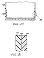
- the chassis sealing surfaces have protruding ribs extending therefrom to improve the quality of the seal.
- These ribs e.g. ribs 1282, 1284, 1286 (FIG. 15) extend generally transverse to the longitudinal axis of the reservoir.
- the ribs concentrate the heat staker force during the heat staking operation to attach the bag films to improve the heat stake attachment.
- the spaces between the ribs also provide space for molten chassis material to flow during the heat stake. Multiple ribs are provided to provide redundant attach features and strength.
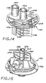
- FIG. 14 shows the chassis prior to attachment of the septa 1214 and 1216.
- septa 1214 and 1216 are secured at the respective ends of the towers 1108 and 1110 by crimp caps 1218, 1220.
- a spring 1222 presses a sealing ball 1224 against the septum 1216. This is because the ink seal is critical; if the septum 1216 takes on a compression set, it is important that the fluid outlet not leak. In contrast, the air inlet can take on a set without an issue, and so in this exemplary embodiment, no additional sealing structure is employed.
- FIGS. 9, 10, 14 and 15 The routing of ILS leads or traces 1148, 1150 from the contact pads 1138A, 1138B, and 1140B and 1140B toward the ILS coils 1130, 1132 is illustrated in FIGS. 9, 10, 14 and 15.
- the chassis 1120 supports the flexible circuit portions 1148 and 1150; an o-ring seal 1152 provides a seal between the chassis periphery and the neck 1154 of the bottle-shaped pressure vessel 1104.
- respective routing surfaces 1156, 1158 are provided in the chassis 1120 for routing the ILS flexible circuit traces 1148, 1150 between the o-ring 1152 and the chassis.
- FIG. 10 shows the flat zones 1160, 1162 formed on the interior surface of the neck 1154 of the pressure vessel to match the flat portions of the routing surface 1156, 1158.
- the chassis 1120 defines a circumferential channel 1226 (FIGS. 11, 14, 15) that supports the o-ring 1228 providing a seal between the chassis and the pressure vessel.
- the chassis 1120 also provides flexible circuit routing surfaces 1156, 1158 for the flexible circuit 1170 to pass from the flat outside surface 1204 of the chassis, between the o-ring and the flex routing surface, and into the pressure vessel.
- the pressure vessel has an inside surface whose shape matches an outside surface on the chassis. Portions of the chassis are flat, for routing the flexible circuit traces; the vessel has flat portions or zones 1160, 1162 to match the flat portions of the chassis.
- the o-ring material is a relatively stiff material such as EPDM, silicon rubber, or neoprene, having a 70 shore-A hardness. Enhancement of the seal in the area of the ILS lead pathways, i.e. where the o-ring passes over the flexible circuit, is obtained using such a stiff material because it works in combination with a pressure sensitive adhesive used to attach the ILS leads. The firm o-ring material is believed to squeeze the adhesive out around the edges of the ILS leads, and fill small discontinuity cavities adjacent to these edges.
- the underside of the flexible circuit 1170 has a coating of pressure-sensitive adhesive underlying specific areas of the flexible circuit. Adhesive underlies the coils and areas which will come into contact with the chassis member.
- FIG. 16B is an isometric view of the collapsible reservoir 114, attached to the chassis 1120, with the ILS flexible circuit attached to the reservoir and to the chassis.
- the reservoir assembly is inserted into the pressure chamber through the vessel opening.
- the o-ring provides a seal fit against the interior surface 1162 of the pressure vessel.
- An aluminum crimp ring 1280 (FIG. 10) is installed to secure the chassis 1120 and reservoir structure in place.
- the chassis 1120 is an integrally molded thermoplastic part, providing an o-ring support and sealing surface 1226, routing surfaces 1156, 1158 for ILS traces, two septum towers 1108, 1110 and their respective communicating conduits 1200, 1202, a surface 1204 for supporting electrical interconnection, the upstanding member 1208, and support and sealing surfaces 1210, 1212 for the collapsible bag.
- the chassis 1120 is an integrally molded thermoplastic part, providing an o-ring support and sealing surface 1226, routing surfaces 1156, 1158 for ILS traces, two septum towers 1108, 1110 and their respective communicating conduits 1200, 1202, a surface 1204 for supporting electrical interconnection, the upstanding member 1208, and support and sealing surfaces 1210, 1212 for the collapsible bag.
- Another advantage of an integrally molded chassis is dimensional accuracy. When ink container 110 is installed into a printing system, the electrical, air and fluidic connectors must engage corresponding connectors associated with the printing system at the ink supply station 100.
- the end cap 1104 provides several functions. These include keying functions for preventing insertion of an ink container of the wrong type, e.g the wrong ink type or color, or ink reservoir size, into a particular supply station bay.
- the cap also serves aligning functions in ensuring proper alignment of an ink container with the supply station bay structural components.
- the cap also includes protective structure which protects the ink and air towers of the chassis from physical damage.
- leading end cap 1104 is an injection-molded part, fabricated from polypropylene.
- the leading end cap 1104 is secured onto the neck of the pressure vessel by engagement of locking features on the cap and the neck region of the pressure vessel.
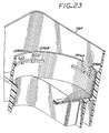
- the cap 1104 includes a cylindrical engagement structure 1244 (FIGS. 19, 23) with two pairs 1246A, 1246B of inwardly protruding engagement surfaces for engaging corresponding a flange 1252B of the neck of the pressure vessel to secure the cap 1104 into registered position on the pressure vessel.
- the surfaces 1246A, 1246B are spaced around the periphery of the engagement structure 1244.
- Each engagement surface 1246A, 1246B includes a ramp surface 1248A, 1246B for riding over the flange 1252B as the cap is pressed onto the neck of the pressure vessel.
- the transverse end (in relation to the longitudinal axis of the container) of the cap 1104 further includes a flat surface 1256 into which openings 1254 is formed.
- a key-shaped boss or wall structure 1258 Surrounding the opening 1254 is a key-shaped boss or wall structure 1258.
- the wall structure 1258 provides a protective wall around the towers 1108 and 1110 and electrical interconnect contacts after installation of the cap, thereby protecting these components from physical damage.
- the underside of the flat surface 1256 provides a stop surface against which the rim of the pressure vessel registers as the cap 1104 is pressed on. Once the surfaces 1246 have engaged the vessel rim 1250, the cap is securely locked into position on the pressure vessel, and cannot be removed without breaking the locking features.
- respective keying and aligning features 1240 and 1242 are provided at opposite sides of the leading cap 1104. These features prevent major ink incompatibilities. By their asymmetry, they prevent backwards insertion (180 degree) installation in the ink supply station relative to a direction of installation.
- feature set 1240 is a variable feature for defining the color of the ink disposed in the container reservoir. This is achieved by the geometry of the feature 1240.
- FIG. 24 illustrates six possible cap/feature configurations.
- cap 1104-1 employs color identifying feature 1240A, which specifies the color yellow in this case.
- cap 1104-2 employs feature 1240B (magenta)
- cap 1104-3 employs feature 1240C (cyan)
- cap 1104-4 employs feature 1240D (black)
- cap 1104-5 employs feature 1104-5 (first other color)
- cap 1104-6 employs feature 1240F.
- Each ink supply station bay has provided therein corresponding features which permit only an ink container with the proper color feature set to be docked at the bay. The interaction of the corresponding features on the cap and the supply station bay further provide aligning functions to properly align the cap and container with the bay. This increases the reliability of the ink, pressurized air system and electrical connections made between the ink supply station bay and the ink container.
- the second keying features 1242 are also employed to provide keying and identifying functions.
- the features 1242 comprise a set of thin fins protruding from the side of the cap.
- the number of fins and spacing between the fins represent a code identifying product type, which can include type of ink, reservoir capacity, and the like.
- each ink supply station bay has provided therein corresponding features which permit only an ink container with the proper product type feature set to be fully inserted into a bay for mating connection to the ink system. This will prevent contamination of the system with improper ink types, for example.
- the features 1242 provide aligning functions, in the same manner as described above with respect to features 1240.
- FIG. 25 represents several different possible configurations of the feature set 1242, showing feature sets 1242A-1242F for different configurations of caps 1104-7 to 1104-12.
- the ink supply station bay is provided with keying features which correspond to the feature 1242, preventing insertion of an ink container which does not have the corresponding key feature, preventing docking of an ink container of the wrong product type in a given supply station bay.
- a set of caps can have identical features 1242, representing a particular product type, while having different features 1240, representing different ink colors for containers of the same product type.
- the trailing end cap 1106 provides a plurality of mechanical functions.
- the trailing cap 1106 provides an enlarged head to prevent backward insertion in the ink supply station 100.
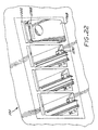
- the trailing cap provides latch surfaces 1230 and 1232 (FIG. 6) which engage corresponding features at the ink supply station when the container is docked to secure the container in a latched position, as is described more fully in the above referenced co-pending application entitled METHOD AND APPARATUS FOR SECURING AN INK CONTAINER, WO-A- 98 55 320.
- These supply station features are generally illustrated in FIG. 22 as features 1270.
- the trailing cap is attached to the pressure vessel in this exemplary embodiment by adhesive. This is illustrated in FIGS. 20 and 21.
- the trailing end of the pressure vessel is reduced in width dimension, and the cap 1106 is appropriately sized to fit over the reduced size end of the vessel (FIG. 21).
- the cap 1106 is secured in place by a layer 1290 of adhesive, in this exemplary embodiment.
- the trailing cap includes all of the user-viewable surfaces of the container when it is inserted into the ink supply station bay. For this exemplary embodiment, only surface 1106B (FIG. 22) is visible when the container is inserted into the bay.
- the advantage of this feature is that stringent cosmetic requirements for a consumer product such as the ink container are limited to a single part (i.e. the cap 1106) of limited surface area.
- Another advantage is that the trailing cap 1106 is added at the end of the assembly process, so that it will not be marred or scratched during preceding steps of the assembly.
- a visible color indicia swatch or element 1288 is a visual indication of the color of the ink disposed within the container, and matches a corresponding swatch 1002 disposed on the housing for the supply station bay, as shown in FIG. 22.
- the swatches 1288 and 1002 can be labels adhesively attached, in one exemplary embodiment. Alternatively the elements 1288, 1002 can be text describing the color.
- the ink container can be assembled in a highly efficient manner, as a result of the multiple functions provided by the chassis member. With efficient assembly, the cost can be minimized, and the reliability of the finished product is improved.
- FIG. 26 is a flow chart showing illustrative steps in the assembly of an ink container in accordance with the invention.
- a chassis element 1120 and reservoir bag having an open end are provided (step 1502).
- the open end of the bag is then sealed to the keel of the chassis member by a heat staking process (step 1504), and the bag/chassis assembly is tested for leaks (step 1508).
- the ILS flexible circuit is now attached to the flat chassis surface 1204, using the pressure sensitive adhesive applied to the corresponding surface region of the circuit substrate (step 1510).
- the ILS flexible circuit After attachment of the ILS circuit at the surface 1204, the ILS flexible circuit is bent to follow the electrical pathways 1156, 1158 provided by the chassis member 1120, and the coils and stiffeners are attached to the side walls of the bag, again with pressure sensitive adhesive (step 1512).
- the o-ring 1152 is stretched over the front of the chassis member, and placed in its channel provided by the chassis member (step 1514).
- FIG. 27 indicates the insertion of the chassis/bag/ILS sub-assembly into the opening of the pressure vessel 1102.
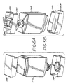
- FIG. 28 shows the assembled pressure vessel and ink container, in exploded view with the caps 1104, 1106.
- the leading and trailing caps are attached to the pressure vessel (step 1526) in the manner described above.
- the reservoir is filled with ink through the ink tower passageway (step 1528) to complete the assembly process.
- the ink container supports high ink flow rates, e.g. for large format printing and plotting applications, high speed color copiers, line printer, etc.
- the risk of a severe ink leak is greatly reduced because the flaccid bag ink reservoir is contained within the air tight pressure vessel.
- the number of hermetic seals is reduced, due to the multi-function chassis member.
- the ink level within the container can be sensed through the use of the inductive coils and ink level sensing circuits. Top down assembly of the container is achieved.
- the reliability of the ink container is very high. Water vapor loss through diffusion from an external environment into the ink reservoir is reduced because the region between the flaccid bag and the pressure vessel becomes humidified.
- Ink can be withdrawn from the reservoir with the container in any orientation.
- the containers do not need to have an integral air or ink pump, and so an array of throughput needs can be met by the ink container. Stresses due to pressurization on the flaccid bag are reduced since forces are balanced across the bag area when compared to pressurization systems that press on the bag film, such as spring bag systems. Pressure drops through the system are relatively low.
- the ink reservoir can be filled with ink through the same ink port used to connect to the system, and so an extra fill port is not needed.
Claims (18)
- Ein Tintenbehälter zum Halten eines mit Druck beaufschlagten Tintenvorrats, der folgende Merkmale aufweist:ein Druckgefäß (1102) zum Definieren einer mit Druck beaufschlagten inneren Kammer;ein zusammenfallfähiges Tintenreservoir (114) zum Halten eines Vorrats an flüssiger Tinte, wobei das Reservoir in der mit Druck beaufschlagten Kammer angeordnet ist;eine elektrische Schaltungsanordnung (1170), die an dem zusammenfallfähigen Tintenreservoir befestigt ist, zum Liefern von elektrischen Signalen, die eine Tintenmenge in dem Reservoir angeben;ein erstes Gehäusebauglied (1120), das folgende Merkmale aufweist:einen Tintenauslaß (1110) zum Bereitstellen eines Tintenweges (1202) von außerhalb des Druckgefäßes zu dem Tintenreservoir; undeine Mehrzahl von Behälterkontakten (1138A, 1138B, 1140A, 1140B), die auf der Außenoberfläche des ersten Gehäusebauglieds angeordnet ist, wobei die Mehrzahl von Behälterkontakten (1138A, 1138B, 1140A, 1140B) durch eine Mehrzahl von leitfähigen Anschlußleitungen (1142, 1144), die von der Kammer durch eine Gefäßöffnung zur Verbindung mit den Behälterkontakten verläuft, mit der elektrischen Schaltungsanordnung (1170) gekoppelt ist, wobei das erste Gehäusebauglied ausgelegt ist, um eine Dichtung um die leitfähigen Anschlußleitungen (1142, 1144) und den Tintenweg (1202) bereitzustellen, um dadurch einen Luftdruck, der höher ist als ein Umgebungsdruck, in der Druckkammer aufrechtzuerhalten, und wobei die Mehrzahl von Behälterkontakten (1138A, 1138B, 1140A, 1140B) ausgelegt ist, um die elektrischen Signale, die eine Tintenmenge in dem Tintenreservoir (114) angeben, an eine Sensorsteuerung zu übermitteln.
- Der Behälter gemäß Anspruch 1, bei dem das erste Gehäusebauglied ferner eine Vorrichtung (1108) zum Bereitstellen eines Lufteinlaßweges (1200) durch das Gefäß und zum Kommunizieren mit der mit Druck beaufschlagten Kammer zum Zweck einer Verbindung mit einem Vorrat (70) an mit Druck beaufschlagtem Gas, um den Luftdruck der mit Druck beaufschlagten Kammer aufrechtzuerhalten, aufweist.
- Der Behälter gemäß Anspruch 2, bei dem sich der Lufteinlaßweg (1200) durch die Druckgefäßöffnung erstreckt.
- Der Behälter gemäß einem der vorhergehenden Ansprüche, bei dem das Druckgefäß (1102) ein unitäres Einfassungsbauglied ist und die Öffnung die einzige in dem Einfassungsbauglied definierte Öffnung ist.
- Der Behälter gemäß einem der vorhergehenden Ansprüche, der ferner einen in dem zusammenfallfähigen Tintenreservoir (114) angeordneten Vorrat an flüssiger Tinte aufweist.
- Der Behälter gemäß einem der vorhergehenden Ansprüche, bei dem das erste Gehäusebauglied ein komprimierbares Bauglied (1152) umfaßt.
- Der Behälter gemäß Anspruch 6, bei dem das komprimierbare Bauglied (1152) einen aus einem elastischen Material hergestellten O-Ring umfaßt.
- Der Behälter gemäß einem der vorhergehenden Ansprüche, bei dem das zusammenfallfähige Tintenreservoir (114) einen ersten flexiblen Wandabschnitt (1114) und einen zweiten flexiblen Wandabschnitt (1116) umfaßt, wobei die Wandabschnitte zueinander zusammenfallen, wenn Tinte aus dem Reservoir entnommen wird, und bei dem die elektrische Schaltungsanordnung (1170) eine erste leitfähige Spule (1130), die an einer Außenseite des ersten Wandabschnitts befestigt ist, eine zweite leitfähige Spule (1132), die an einer Außenseite des zweiten Wandabschnitts befestigt ist, einen ersten Satz von elektrischen Anschlußleitungen (1142), die an der ersten Spule befestigt sind und durch die Gefäßöffnung zu einem ersten Satz von elektrischen Kontakten (1138A, 1138B) verlaufen, und einen zweiten Satz von elektrischen Anschlußleitungen (1144), die an der zweiten Spule befestigt sind und durch die Gefäßöffnung zu einem zweiten Satz von elektrischen Kontakten (1140A, 1140B) verlaufen, umfaßt, wobei der erste Satz von elektrischen Kontakten und der zweite Satz von elektrischen Kontakten außerhalb der mit Druck beaufschlagten Kammer angeordnet sind.
- Ein Tintenbehälter gemäß einem der Ansprüche 1 bis 7, der ferner einen elektrischen Übertragungsweg aufweist, der die elektrische Schaltungsanordnung mit den Behälterkontakten (1138A, 1138B, 1140A, 1140B) koppelt, wobei der elektrische Übertragungsweg eine Dichtungszone (20) durchquert, die die mit Druck beaufschlagte Region von der Außenatmosphäre trennt.
- Ein Tintenbehälter gemäß Anspruch 9, wobei der Tintenbehälter in einer ersten Richtung installiert ist, der elektrische Übertragungsweg ein mit der Schaltungsanordnung verbundenes erstes Segment aufweist, wobei das erste Segment im wesentlichen mit der ersten Richtung ausgerichtet ist.
- Ein Tintenbehälter gemäß Anspruch 10, bei dem der elektrische Übertragungsweg ein zweites Segment aufweist, das mit dem ersten Segment verbunden ist, wobei das zweite Segment eine rechtwinklige Biegung aufweist, um es dem Übertragungsweg zu ermöglichen, mit den Behälterkontakten verbunden zu werden.
- Ein Tintenbehälter gemäß einem der Ansprüche 9, 10 oder 11, bei dem der elektrische Übertragungsweg durch eine flexible Schaltung bereitgestellt ist.
- Ein Tintenbehälter gemäß einem der vorhergehenden Ansprüche, bei dem die Öffnung einen flachen Abschnitt (1162) umfaßt, der eine flache Oberfläche liefert, über die der elektrische Übertragungsweg geroutet werden kann.
- Ein Tintenbehälter gemäß einem der vorhergehenden Ansprüche, bei dem das elektrische Signal den Grad des Zusammenfallens des Reservoirs angibt.
- Ein Tintenbehälter gemäß einem der vorhergehenden Ansprüche, wobei der Behälter für ein Tintenstrahldrucksystem gedacht ist, wobei das Drucksystem einen Druckkopf zum Ausstoßen von Tinte auf ein Medium aufweist.
- Ein Tintenbehälter gemäß einem der vorhergehenden Ansprüche, bei dem das Druckgefäß eine Halsregion aufweist, die sich von dem Druckgefäß nach außen hin zu einem distalen Ende erstreckt, und bei dem die Öffnung an dem distalen Ende angeordnet ist.
- Ein Verfahren zum Zusammenbauen eines Tintenbehälters, der in einem Tintenstrahldrucksystem installiert werden soll, wobei das Tintenstrahldrucksystem einen Druckkopf zum Ausstoßen von Tinte auf ein Medium aufweist, wobei das Verfahren folgende Schritte aufweist:(a) Bereitstellen (1502) eines ersten Gehäusebauglieds (1120), das mit einem Fluidauslaß einen Fluiddurchgang (1202) zum Liefern von Tinte an den Druckkopf umfaßt;(b) fluidisches Koppeln (1504) eines zusammenfallfähigen Reservoirs (114) mit dem Fluidauslaß;(c) Befestigen (1510) einer Mehrzahl von Behälterkontakten an einer Außenoberfläche des ersten Gehäusebauglieds;(d) Befestigen (1512) einer Tintenpegelerfassungsschaltung (1170) an dem zusammenfallfähigen Reservoir;(e) Routen (1512) einer Mehrzahl von elektrischen Wegen (1142, 1144), die die Erfassungsschaltung mit den Behälterkontakten koppeln;(f) Befestigen eines zweiten Gehäusebauglieds (1102) an dem ersten Gehäusebauglied, wobei das zweite Gehäusebauglied entlang einer Dichtungszone an das erste Gehäusebauglied anstößt, wobei das erste und das zweite Gehäusebauglied ein Druckgefäß bilden, das das zusammenfallfähige Reservoir umgibt, wobei das Druckgefäß und das zusammenfallfähige Reservoir zwischen denselben eine mit Druck beaufschlagte Region definieren und wobei die Mehrzahl von elektrischen Wegen durch die Dichtung von der mit Druck beaufschlagten Region zu der Außenatmosphäre verläuft.
- Das Verfahren gemäß Anspruch 17, bei dem das zweite Gehäusebauglied (1102) ein flaschenförmiges Bauglied ist, das an einem Ende eine Öffnung aufweist, und bei dem das zusammenfallfähige Reservoir (114) durch die Öffnung aufgenommen wird, wenn das erste Gehäusebauglied an dem zweiten Gehäusebauglied befestigt wird.
Priority Applications (1)
| Application Number | Priority Date | Filing Date | Title |
|---|---|---|---|
| EP03075278A EP1310372B1 (de) | 1997-06-04 | 1998-06-03 | Tintenbehälter für unter Druck stehende Tinte mit Tintenpegelführer |
Applications Claiming Priority (3)
| Application Number | Priority Date | Filing Date | Title |
|---|---|---|---|
| US868773 | 1997-06-04 | ||
| US08/868,773 US6585359B1 (en) | 1997-06-04 | 1997-06-04 | Ink container providing pressurized ink with ink level sensor |
| PCT/US1998/011417 WO1998055322A1 (en) | 1997-06-04 | 1998-06-03 | Ink container providing pressurized ink with ink level sensor |
Related Child Applications (1)
| Application Number | Title | Priority Date | Filing Date |
|---|---|---|---|
| EP03075278A Division EP1310372B1 (de) | 1997-06-04 | 1998-06-03 | Tintenbehälter für unter Druck stehende Tinte mit Tintenpegelführer |
Publications (2)
| Publication Number | Publication Date |
|---|---|
| EP1011980A1 EP1011980A1 (de) | 2000-06-28 |
| EP1011980B1 true EP1011980B1 (de) | 2003-03-12 |
Family
ID=25352288
Family Applications (2)
| Application Number | Title | Priority Date | Filing Date |
|---|---|---|---|
| EP03075278A Expired - Lifetime EP1310372B1 (de) | 1997-06-04 | 1998-06-03 | Tintenbehälter für unter Druck stehende Tinte mit Tintenpegelführer |
| EP98925213A Expired - Lifetime EP1011980B1 (de) | 1997-06-04 | 1998-06-03 | Tintenbehälter für unter druck stehende tinte mit tintenpegelführer |
Family Applications Before (1)
| Application Number | Title | Priority Date | Filing Date |
|---|---|---|---|
| EP03075278A Expired - Lifetime EP1310372B1 (de) | 1997-06-04 | 1998-06-03 | Tintenbehälter für unter Druck stehende Tinte mit Tintenpegelführer |
Country Status (8)
| Country | Link |
|---|---|
| US (1) | US6585359B1 (de) |
| EP (2) | EP1310372B1 (de) |
| JP (1) | JP4493734B2 (de) |
| KR (1) | KR100519139B1 (de) |
| CN (1) | CN1116175C (de) |
| DE (2) | DE69832642T2 (de) |
| ES (2) | ES2194322T3 (de) |
| WO (1) | WO1998055322A1 (de) |
Families Citing this family (46)
| Publication number | Priority date | Publication date | Assignee | Title |
|---|---|---|---|---|
| US6116723A (en) * | 1998-03-09 | 2000-09-12 | Hewlett-Packard | Low cost pressurizable ink container |
| US6183072B1 (en) | 1998-04-29 | 2001-02-06 | Hewlett-Packard Company | Seal using gasket compressed normal to assembly axis of two parts |
| CN1880084B (zh) | 1998-05-18 | 2013-02-13 | 精工爱普生株式会社 | 喷墨打印设备及其墨盒 |
| CN1173830C (zh) | 1999-10-12 | 2004-11-03 | 精工爱普生株式会社 | 用于喷墨打印设备的墨盒 |
| DE60119597T2 (de) * | 2000-01-21 | 2007-04-26 | Seiko Epson Corp. | Tintenpatrone und Tintenstrahldruckvorrichtung mit einer derartigen Tintenpatrone |
| ES2382127T3 (es) | 2000-01-21 | 2012-06-05 | Seiko Epson Corporation | Cartucho de tinta para uso con aparato de registro y aparato de registro de inyección de tinta |
| US7048348B2 (en) | 2000-10-17 | 2006-05-23 | Seiko Epson Corporation | Ink bag recording apparatus incorporating the same |
| JP3697213B2 (ja) * | 2001-02-09 | 2005-09-21 | キヤノン株式会社 | 液体収納容器、および液体の撹拌方法 |
| US7086722B2 (en) | 2001-11-12 | 2006-08-08 | Seiko Epson Corporation | Ink cartridge |
| US6760556B2 (en) | 2002-07-16 | 2004-07-06 | Cf Technologies | Sealing member and toner container provided with such a sealing member |
| US9508046B2 (en) * | 2003-07-22 | 2016-11-29 | Hewlett-Packard Development Company, L.P. | Methods and systems for providing web content to a printing device |
| US7384133B2 (en) | 2003-08-08 | 2008-06-10 | Seiko Epson Corporation | Liquid container capable of maintaining airtightness |
| JP4509525B2 (ja) * | 2003-10-10 | 2010-07-21 | 理想科学工業株式会社 | インク容器 |
| US20050219281A1 (en) * | 2004-03-24 | 2005-10-06 | Takeo Seino | Attachment and liquid supplying |
| US20060095483A1 (en) * | 2004-04-23 | 2006-05-04 | Waratek Pty Limited | Modified computer architecture with finalization of objects |
| US7844665B2 (en) | 2004-04-23 | 2010-11-30 | Waratek Pty Ltd. | Modified computer architecture having coordinated deletion of corresponding replicated memory locations among plural computers |
| WO2006110937A1 (en) | 2005-04-21 | 2006-10-26 | Waratek Pty Limited | Modified computer architecture with coordinated objects |
| US7429101B2 (en) * | 2005-04-22 | 2008-09-30 | Hewlett-Packard Development Company, L.P. | Ink supply with ink/air separator assembly that is isolated from ink until time of use |
| JP4277850B2 (ja) | 2005-11-30 | 2009-06-10 | ブラザー工業株式会社 | リフィルユニット |
| US7284848B2 (en) | 2005-11-28 | 2007-10-23 | Brother Kogyo Kabushiki Kaisha | Ink cartridges |
| DE202006020420U1 (de) * | 2005-11-28 | 2008-06-19 | Brother Kogyo K.K., Nagoya | Tintenpatrone, Hauptkörper und Nachfülleinheit |
| JP4144637B2 (ja) | 2005-12-26 | 2008-09-03 | セイコーエプソン株式会社 | 印刷材収容体、基板、印刷装置および印刷材収容体を準備する方法 |
| JP2007253468A (ja) * | 2006-03-23 | 2007-10-04 | Canon Inc | インクジェット記録ヘッドカートリッジ |
| JP4806616B2 (ja) * | 2006-09-29 | 2011-11-02 | 富士フイルム株式会社 | インクカートリッジ及びインクジェット記録装置 |
| US20080122904A1 (en) * | 2006-11-28 | 2008-05-29 | Benq Corporation | Printing apparatus having inkjet cartridge |
| US8322835B2 (en) * | 2007-02-19 | 2012-12-04 | Seiko Epson Corporation | Sealing structure of fluid container, and method of manufacturing and reusing fluid container |
| JP2008230214A (ja) * | 2007-02-19 | 2008-10-02 | Seiko Epson Corp | 流体導出部のシール構造体及びシール方法並びに流体収容容器、再充填流体収容容器及びその再充填方法 |
| WO2008109535A2 (en) * | 2007-03-02 | 2008-09-12 | Marvell International Ltd. | Ink supply for a hand-held ink jet printer |
| US7874660B2 (en) * | 2007-10-10 | 2011-01-25 | Hewlett-Packard Development Company, L.P. | Closure and connector for a supply container |
| GB0720139D0 (en) * | 2007-10-12 | 2007-11-28 | Videojet Technologies Inc | Ink jet printing |
| US9067425B2 (en) * | 2007-10-12 | 2015-06-30 | Videojet Technologies Inc. | Fluid cartridge for an inkjet printer |
| GB0720289D0 (en) * | 2007-10-12 | 2007-11-28 | Videojet Technologies Inc | Ink jet printer |
| GB0720288D0 (en) * | 2007-10-12 | 2007-11-28 | Videojet Technologies Inc | Container and method for liquid storage and dispensing |
| GB0720290D0 (en) * | 2007-10-12 | 2007-11-28 | Videojet Technologies Inc | Ink jet printer |
| JP2011173398A (ja) * | 2010-02-25 | 2011-09-08 | Sii Printek Inc | 圧力緩衝装置、液体噴射ヘッド、液体噴射装置、及び圧力緩衝方法 |
| JP5506452B2 (ja) * | 2010-02-25 | 2014-05-28 | エスアイアイ・プリンテック株式会社 | 圧力緩衝器、液体噴射ヘッド及び液体噴射装置 |
| US10647123B2 (en) | 2012-07-23 | 2020-05-12 | Seiko Epson Corporation | Refilled cartridge and method for manufacturing refilled cartridge |
| US8608299B1 (en) * | 2012-12-21 | 2013-12-17 | Jetbest Corporation | Ink cartridge with replaceable ink bag |
| JP6299068B2 (ja) * | 2013-03-05 | 2018-03-28 | セイコーエプソン株式会社 | 液体収容容器 |
| JP6137943B2 (ja) * | 2013-06-03 | 2017-05-31 | 株式会社リコー | 液体収容容器 |
| JP6144210B2 (ja) * | 2014-01-16 | 2017-06-07 | 株式会社キーエンス | インクジェット記録装置、インクジェット記録装置のカートリッジ及びボトル |
| EP3102416B1 (de) * | 2014-02-04 | 2021-04-14 | Hewlett-Packard Development Company, L.P. | Sensoranordnungen und verfahren zur identifizierung des tintenstandes |
| CN108290415B (zh) | 2016-02-05 | 2020-03-20 | 惠普发展公司,有限责任合伙企业 | 打印头 |
| US11040545B2 (en) | 2016-07-14 | 2021-06-22 | Hewlett-Packard Development Company, L.P. | Fluid level sensing dependent on write command |
| WO2018013125A1 (en) | 2016-07-14 | 2018-01-18 | Hewlett-Packard Development Company, L.P. | Fluid level sensing independent of write command |
| EP3962753A4 (de) * | 2019-08-02 | 2022-11-30 | Hewlett-Packard Development Company, L.P. | Zwischenbehälter für kontinuierliche fluidabgabe |
Family Cites Families (27)
| Publication number | Priority date | Publication date | Assignee | Title |
|---|---|---|---|---|
| US3371350A (en) | 1966-09-09 | 1968-02-27 | Hewlett Packard Co | Ink supply system with pressure regulating diaphragm |
| US3950761A (en) | 1973-01-04 | 1976-04-13 | Casio Computer Co., Ltd. | Ink pressurizing apparatus for an ink jet recorder |
| US4183031A (en) | 1976-06-07 | 1980-01-08 | Silonics, Inc. | Ink supply system |
| GB2053486B (en) * | 1979-06-11 | 1983-08-10 | Rescon Ab | Device for determining the level of a melt |
| JPS5627353A (en) | 1979-08-15 | 1981-03-17 | Canon Inc | Ink jet recording device |
| GB2063175B (en) | 1979-11-06 | 1984-02-15 | Shinshu Seiki Kk | Ink jet printer |
| US4414886A (en) | 1979-11-26 | 1983-11-15 | Gonzales Louis P | Fruit squeezer |
| JPS5734990A (en) * | 1980-08-12 | 1982-02-25 | Canon Inc | Apparatus for detecting ink residual amount |
| DE3043810A1 (de) | 1980-11-20 | 1982-06-24 | Siemens AG, 1000 Berlin und 8000 München | Vorrichtung zur ueberwachung des tintenvorrats in tintenschreibeinrichtungen |
| US4432005A (en) | 1982-05-10 | 1984-02-14 | Advanced Color Technology, Inc. | Ink control system for ink jet printer |
| US4558326A (en) | 1982-09-07 | 1985-12-10 | Konishiroku Photo Industry Co., Ltd. | Purging system for ink jet recording apparatus |
| US4604633A (en) | 1982-12-08 | 1986-08-05 | Konishiroku Photo Industry Co., Ltd | Ink-jet recording apparatus |
| DE3344447A1 (de) * | 1982-12-08 | 1984-06-14 | Konishiroku Photo Ind | Ink-jet-aufzeichnungsvorrichtung |
| JPS59204566A (ja) * | 1983-05-09 | 1984-11-19 | Ricoh Co Ltd | オンデマンド型インクジエツトプリンタ−におけるインクカ−トリツジのインク袋 |
| DE3422504A1 (de) * | 1984-06-16 | 1986-01-02 | Olympia Werke Ag, 2940 Wilhelmshaven | Endanzeigevorrichtung des tintenvorrats in einem tintenbehaelter mit einem flexiblen tintensack |
| US4568954A (en) | 1984-12-06 | 1986-02-04 | Tektronix, Inc. | Ink cartridge manufacturing method and apparatus |
| US4551734A (en) | 1984-12-06 | 1985-11-05 | Tektronix, Inc. | Ink cartridge with ink level sensor |
| DE3524250A1 (de) | 1985-07-06 | 1987-01-08 | Philips Patentverwaltung | Anordnung zur kontrolle des fuellstandes eines tintenbehaelters |
| US4714937A (en) | 1986-10-02 | 1987-12-22 | Hewlett-Packard Company | Ink delivery system |
| JPS63207652A (ja) * | 1987-02-25 | 1988-08-29 | Seiko Epson Corp | インク残量検出装置 |
| EP0660092B1 (de) | 1987-04-15 | 2003-07-30 | Canon Kabushiki Kaisha | Ein Flüssigkeitsrestmengendetektor und ein Flüssigkeitseinspritzregistriergerät mit diesem Detektor |
| JPS6418087A (en) | 1987-07-14 | 1989-01-20 | Toshiba Corp | Electromagnetic induction detector |
| US5051921A (en) * | 1989-11-30 | 1991-09-24 | David Sarnoff Research Center, Inc. | Method and apparatus for detecting liquid composition and actual liquid level |
| US5745137A (en) | 1992-08-12 | 1998-04-28 | Hewlett-Packard Company | Continuous refill of spring bag reservoir in an ink-jet swath printer/plotter |
| US5583545A (en) | 1994-10-31 | 1996-12-10 | Hewlett-Packard Company | Ink level detection in a pressure regulated pen |
| US5635962A (en) * | 1995-07-24 | 1997-06-03 | Hewlett-Packard Company | Capacitive ink level detection sensor |
| DE19642899A1 (de) | 1996-04-17 | 1997-10-23 | Hewlett Packard Co | Induktive Tintenpegelerfassungsvorrichtung für Tintenvorräte |
-
1997
- 1997-06-04 US US08/868,773 patent/US6585359B1/en not_active Expired - Lifetime
-
1998
- 1998-06-03 DE DE69832642T patent/DE69832642T2/de not_active Expired - Lifetime
- 1998-06-03 ES ES98925213T patent/ES2194322T3/es not_active Expired - Lifetime
- 1998-06-03 CN CN98805767A patent/CN1116175C/zh not_active Expired - Fee Related
- 1998-06-03 JP JP50281199A patent/JP4493734B2/ja not_active Expired - Fee Related
- 1998-06-03 ES ES03075278T patent/ES2249676T3/es not_active Expired - Lifetime
- 1998-06-03 DE DE69812125T patent/DE69812125T2/de not_active Expired - Lifetime
- 1998-06-03 WO PCT/US1998/011417 patent/WO1998055322A1/en active IP Right Grant
- 1998-06-03 EP EP03075278A patent/EP1310372B1/de not_active Expired - Lifetime
- 1998-06-03 EP EP98925213A patent/EP1011980B1/de not_active Expired - Lifetime
- 1998-06-03 KR KR10-1999-7011313A patent/KR100519139B1/ko not_active IP Right Cessation
Also Published As
| Publication number | Publication date |
|---|---|
| CN1259088A (zh) | 2000-07-05 |
| WO1998055322A1 (en) | 1998-12-10 |
| DE69832642D1 (de) | 2006-01-05 |
| EP1310372B1 (de) | 2005-11-30 |
| EP1011980A1 (de) | 2000-06-28 |
| US6585359B1 (en) | 2003-07-01 |
| ES2249676T3 (es) | 2006-04-01 |
| KR100519139B1 (ko) | 2005-10-06 |
| ES2194322T3 (es) | 2003-11-16 |
| JP2002510253A (ja) | 2002-04-02 |
| WO1998055322A9 (en) | 1999-07-01 |
| CN1116175C (zh) | 2003-07-30 |
| DE69812125T2 (de) | 2003-12-04 |
| EP1310372A2 (de) | 2003-05-14 |
| EP1310372A3 (de) | 2003-07-16 |
| DE69812125D1 (de) | 2003-04-17 |
| JP4493734B2 (ja) | 2010-06-30 |
| DE69832642T2 (de) | 2006-08-24 |
| KR20010013318A (ko) | 2001-02-26 |
Similar Documents
| Publication | Publication Date | Title |
|---|---|---|
| EP1011980B1 (de) | Tintenbehälter für unter druck stehende tinte mit tintenpegelführer | |
| US6010210A (en) | Ink container having a multiple function chassis | |
| US6017118A (en) | High performance ink container with efficient construction | |
| US6164743A (en) | Ink container with an inductive ink level sense | |
| EP0882595B1 (de) | Tintenfüllstandsschätzung mittels Tropfenzählung und Tintenfüllstandsbestimmung | |
| EP1413443A1 (de) | Vor Erschütterungen geschützter Drucksensor in Flüssigkeitsbehältnis | |
| US10434784B2 (en) | Cartridge and connector | |
| EP0839660B1 (de) | Verbindungselement für eine Patrone in einem Tintenstrahldrucker | |
| KR20010013265A (ko) | 교환가능한 잉크 용기 및 오프-축형 프린팅 시스템과오프-축형 프린팅 시스템내로 잉크 용기를 삽입하는 방법 | |
| EP1457340B1 (de) | Tintensack und Vorrichtung zur Tintenerfassung |
Legal Events
| Date | Code | Title | Description |
|---|---|---|---|
| PUAI | Public reference made under article 153(3) epc to a published international application that has entered the european phase |
Free format text: ORIGINAL CODE: 0009012 |
|
| 17P | Request for examination filed |
Effective date: 19991209 |
|
| AK | Designated contracting states |
Kind code of ref document: A1 Designated state(s): DE ES FR GB IT |
|
| RIN1 | Information on inventor provided before grant (corrected) |
Inventor name: KRALL, THOMAS, J. Inventor name: KAMP, DAVID, C. Inventor name: HOUPT, DENNIS, W. Inventor name: WILSON, RHONDA, L. Inventor name: PAWLOWSKI, NORMAN, E., JR. Inventor name: MERRILL, DAVID, O. Inventor name: HMELAR, SUSAN, M. Inventor name: GASVODA, ERIC, L. |
|
| RAP1 | Party data changed (applicant data changed or rights of an application transferred) |
Owner name: HEWLETT-PACKARD COMPANY, A DELAWARE CORPORATION |
|
| 17Q | First examination report despatched |
Effective date: 20010508 |
|
| GRAG | Despatch of communication of intention to grant |
Free format text: ORIGINAL CODE: EPIDOS AGRA |
|
| GRAG | Despatch of communication of intention to grant |
Free format text: ORIGINAL CODE: EPIDOS AGRA |
|
| GRAH | Despatch of communication of intention to grant a patent |
Free format text: ORIGINAL CODE: EPIDOS IGRA |
|
| GRAH | Despatch of communication of intention to grant a patent |
Free format text: ORIGINAL CODE: EPIDOS IGRA |
|
| GRAA | (expected) grant |
Free format text: ORIGINAL CODE: 0009210 |
|
| AK | Designated contracting states |
Designated state(s): DE ES FR GB IT |
|
| REG | Reference to a national code |
Ref country code: GB Ref legal event code: FG4D |
|
| REF | Corresponds to: |
Ref document number: 69812125 Country of ref document: DE Date of ref document: 20030417 Kind code of ref document: P |
|
| REG | Reference to a national code |
Ref country code: ES Ref legal event code: FG2A Ref document number: 2194322 Country of ref document: ES Kind code of ref document: T3 |
|
| ET | Fr: translation filed | ||
| PLBE | No opposition filed within time limit |
Free format text: ORIGINAL CODE: 0009261 |
|
| STAA | Information on the status of an ep patent application or granted ep patent |
Free format text: STATUS: NO OPPOSITION FILED WITHIN TIME LIMIT |
|
| 26N | No opposition filed |
Effective date: 20031215 |
|
| REG | Reference to a national code |
Ref country code: GB Ref legal event code: 732E Free format text: REGISTERED BETWEEN 20120329 AND 20120404 |
|
| REG | Reference to a national code |
Ref country code: ES Ref legal event code: PC2A Owner name: HEWLETT-PACKARD DEVELOPMENT COMPANY, L.P. Effective date: 20120911 |
|
| REG | Reference to a national code |
Ref country code: FR Ref legal event code: PLFP Year of fee payment: 18 |
|
| PGFP | Annual fee paid to national office [announced via postgrant information from national office to epo] |
Ref country code: GB Payment date: 20150527 Year of fee payment: 18 Ref country code: ES Payment date: 20150603 Year of fee payment: 18 Ref country code: DE Payment date: 20150521 Year of fee payment: 18 |
|
| PGFP | Annual fee paid to national office [announced via postgrant information from national office to epo] |
Ref country code: IT Payment date: 20150529 Year of fee payment: 18 Ref country code: FR Payment date: 20150526 Year of fee payment: 18 |
|
| REG | Reference to a national code |
Ref country code: DE Ref legal event code: R119 Ref document number: 69812125 Country of ref document: DE |
|
| GBPC | Gb: european patent ceased through non-payment of renewal fee |
Effective date: 20160603 |
|
| REG | Reference to a national code |
Ref country code: FR Ref legal event code: ST Effective date: 20170228 |
|
| PG25 | Lapsed in a contracting state [announced via postgrant information from national office to epo] |
Ref country code: FR Free format text: LAPSE BECAUSE OF NON-PAYMENT OF DUE FEES Effective date: 20160630 Ref country code: DE Free format text: LAPSE BECAUSE OF NON-PAYMENT OF DUE FEES Effective date: 20170103 |
|
| PG25 | Lapsed in a contracting state [announced via postgrant information from national office to epo] |
Ref country code: GB Free format text: LAPSE BECAUSE OF NON-PAYMENT OF DUE FEES Effective date: 20160603 |
|
| PG25 | Lapsed in a contracting state [announced via postgrant information from national office to epo] |
Ref country code: IT Free format text: LAPSE BECAUSE OF NON-PAYMENT OF DUE FEES Effective date: 20160603 |
|
| REG | Reference to a national code |
Ref country code: ES Ref legal event code: FD2A Effective date: 20180507 |
|
| PG25 | Lapsed in a contracting state [announced via postgrant information from national office to epo] |
Ref country code: ES Free format text: LAPSE BECAUSE OF NON-PAYMENT OF DUE FEES Effective date: 20160604 |