EP1011944B1 - Method and device for processing tires - Google Patents
Method and device for processing tires Download PDFInfo
- Publication number
- EP1011944B1 EP1011944B1 EP19980945077 EP98945077A EP1011944B1 EP 1011944 B1 EP1011944 B1 EP 1011944B1 EP 19980945077 EP19980945077 EP 19980945077 EP 98945077 A EP98945077 A EP 98945077A EP 1011944 B1 EP1011944 B1 EP 1011944B1
- Authority
- EP
- European Patent Office
- Prior art keywords
- mats
- rings
- tires
- bodies
- ring
- Prior art date
- Legal status (The legal status is an assumption and is not a legal conclusion. Google has not performed a legal analysis and makes no representation as to the accuracy of the status listed.)
- Expired - Lifetime
Links
Images


Classifications
-
- B—PERFORMING OPERATIONS; TRANSPORTING
- B29—WORKING OF PLASTICS; WORKING OF SUBSTANCES IN A PLASTIC STATE IN GENERAL
- B29B—PREPARATION OR PRETREATMENT OF THE MATERIAL TO BE SHAPED; MAKING GRANULES OR PREFORMS; RECOVERY OF PLASTICS OR OTHER CONSTITUENTS OF WASTE MATERIAL CONTAINING PLASTICS
- B29B17/00—Recovery of plastics or other constituents of waste material containing plastics
-
- B—PERFORMING OPERATIONS; TRANSPORTING
- B26—HAND CUTTING TOOLS; CUTTING; SEVERING
- B26D—CUTTING; DETAILS COMMON TO MACHINES FOR PERFORATING, PUNCHING, CUTTING-OUT, STAMPING-OUT OR SEVERING
- B26D3/00—Cutting work characterised by the nature of the cut made; Apparatus therefor
- B26D3/003—Cutting work characterised by the nature of the cut made; Apparatus therefor specially adapted for cutting rubber
- B26D3/005—Cutting work characterised by the nature of the cut made; Apparatus therefor specially adapted for cutting rubber for cutting used tyres
-
- B—PERFORMING OPERATIONS; TRANSPORTING
- B29—WORKING OF PLASTICS; WORKING OF SUBSTANCES IN A PLASTIC STATE IN GENERAL
- B29B—PREPARATION OR PRETREATMENT OF THE MATERIAL TO BE SHAPED; MAKING GRANULES OR PREFORMS; RECOVERY OF PLASTICS OR OTHER CONSTITUENTS OF WASTE MATERIAL CONTAINING PLASTICS
- B29B17/00—Recovery of plastics or other constituents of waste material containing plastics
- B29B17/04—Disintegrating plastics, e.g. by milling
- B29B17/0412—Disintegrating plastics, e.g. by milling to large particles, e.g. beads, granules, flakes, slices
-
- B—PERFORMING OPERATIONS; TRANSPORTING
- B29—WORKING OF PLASTICS; WORKING OF SUBSTANCES IN A PLASTIC STATE IN GENERAL
- B29B—PREPARATION OR PRETREATMENT OF THE MATERIAL TO BE SHAPED; MAKING GRANULES OR PREFORMS; RECOVERY OF PLASTICS OR OTHER CONSTITUENTS OF WASTE MATERIAL CONTAINING PLASTICS
- B29B17/00—Recovery of plastics or other constituents of waste material containing plastics
- B29B17/04—Disintegrating plastics, e.g. by milling
- B29B2017/0424—Specific disintegrating techniques; devices therefor
- B29B2017/044—Knives
-
- B—PERFORMING OPERATIONS; TRANSPORTING
- B29—WORKING OF PLASTICS; WORKING OF SUBSTANCES IN A PLASTIC STATE IN GENERAL
- B29B—PREPARATION OR PRETREATMENT OF THE MATERIAL TO BE SHAPED; MAKING GRANULES OR PREFORMS; RECOVERY OF PLASTICS OR OTHER CONSTITUENTS OF WASTE MATERIAL CONTAINING PLASTICS
- B29B17/00—Recovery of plastics or other constituents of waste material containing plastics
- B29B17/04—Disintegrating plastics, e.g. by milling
- B29B2017/0424—Specific disintegrating techniques; devices therefor
- B29B2017/0448—Cutting discs
-
- B—PERFORMING OPERATIONS; TRANSPORTING
- B29—WORKING OF PLASTICS; WORKING OF SUBSTANCES IN A PLASTIC STATE IN GENERAL
- B29K—INDEXING SCHEME ASSOCIATED WITH SUBCLASSES B29B, B29C OR B29D, RELATING TO MOULDING MATERIALS OR TO MATERIALS FOR MOULDS, REINFORCEMENTS, FILLERS OR PREFORMED PARTS, e.g. INSERTS
- B29K2021/00—Use of unspecified rubbers as moulding material
-
- B—PERFORMING OPERATIONS; TRANSPORTING
- B29—WORKING OF PLASTICS; WORKING OF SUBSTANCES IN A PLASTIC STATE IN GENERAL
- B29L—INDEXING SCHEME ASSOCIATED WITH SUBCLASS B29C, RELATING TO PARTICULAR ARTICLES
- B29L2030/00—Pneumatic or solid tyres or parts thereof
-
- Y—GENERAL TAGGING OF NEW TECHNOLOGICAL DEVELOPMENTS; GENERAL TAGGING OF CROSS-SECTIONAL TECHNOLOGIES SPANNING OVER SEVERAL SECTIONS OF THE IPC; TECHNICAL SUBJECTS COVERED BY FORMER USPC CROSS-REFERENCE ART COLLECTIONS [XRACs] AND DIGESTS
- Y02—TECHNOLOGIES OR APPLICATIONS FOR MITIGATION OR ADAPTATION AGAINST CLIMATE CHANGE
- Y02W—CLIMATE CHANGE MITIGATION TECHNOLOGIES RELATED TO WASTEWATER TREATMENT OR WASTE MANAGEMENT
- Y02W30/00—Technologies for solid waste management
- Y02W30/50—Reuse, recycling or recovery technologies
- Y02W30/52—Mechanical processing of waste for the recovery of materials, e.g. crushing, shredding, separation or disassembly
-
- Y—GENERAL TAGGING OF NEW TECHNOLOGICAL DEVELOPMENTS; GENERAL TAGGING OF CROSS-SECTIONAL TECHNOLOGIES SPANNING OVER SEVERAL SECTIONS OF THE IPC; TECHNICAL SUBJECTS COVERED BY FORMER USPC CROSS-REFERENCE ART COLLECTIONS [XRACs] AND DIGESTS
- Y02—TECHNOLOGIES OR APPLICATIONS FOR MITIGATION OR ADAPTATION AGAINST CLIMATE CHANGE
- Y02W—CLIMATE CHANGE MITIGATION TECHNOLOGIES RELATED TO WASTEWATER TREATMENT OR WASTE MANAGEMENT
- Y02W30/00—Technologies for solid waste management
- Y02W30/50—Reuse, recycling or recovery technologies
- Y02W30/62—Plastics recycling; Rubber recycling
-
- Y—GENERAL TAGGING OF NEW TECHNOLOGICAL DEVELOPMENTS; GENERAL TAGGING OF CROSS-SECTIONAL TECHNOLOGIES SPANNING OVER SEVERAL SECTIONS OF THE IPC; TECHNICAL SUBJECTS COVERED BY FORMER USPC CROSS-REFERENCE ART COLLECTIONS [XRACs] AND DIGESTS
- Y10—TECHNICAL SUBJECTS COVERED BY FORMER USPC
- Y10T—TECHNICAL SUBJECTS COVERED BY FORMER US CLASSIFICATION
- Y10T428/00—Stock material or miscellaneous articles
- Y10T428/13—Hollow or container type article [e.g., tube, vase, etc.]
- Y10T428/1352—Polymer or resin containing [i.e., natural or synthetic]
- Y10T428/1362—Textile, fabric, cloth, or pile containing [e.g., web, net, woven, knitted, mesh, nonwoven, matted, etc.]
- Y10T428/1366—Textile, fabric, cloth, or pile is sandwiched between two distinct layers of material unlike the textile, fabric, cloth, or pile layer
-
- Y—GENERAL TAGGING OF NEW TECHNOLOGICAL DEVELOPMENTS; GENERAL TAGGING OF CROSS-SECTIONAL TECHNOLOGIES SPANNING OVER SEVERAL SECTIONS OF THE IPC; TECHNICAL SUBJECTS COVERED BY FORMER USPC CROSS-REFERENCE ART COLLECTIONS [XRACs] AND DIGESTS
- Y10—TECHNICAL SUBJECTS COVERED BY FORMER USPC
- Y10T—TECHNICAL SUBJECTS COVERED BY FORMER US CLASSIFICATION
- Y10T428/00—Stock material or miscellaneous articles
- Y10T428/13—Hollow or container type article [e.g., tube, vase, etc.]
- Y10T428/1352—Polymer or resin containing [i.e., natural or synthetic]
- Y10T428/1386—Natural or synthetic rubber or rubber-like compound containing
-
- Y—GENERAL TAGGING OF NEW TECHNOLOGICAL DEVELOPMENTS; GENERAL TAGGING OF CROSS-SECTIONAL TECHNOLOGIES SPANNING OVER SEVERAL SECTIONS OF THE IPC; TECHNICAL SUBJECTS COVERED BY FORMER USPC CROSS-REFERENCE ART COLLECTIONS [XRACs] AND DIGESTS
- Y10—TECHNICAL SUBJECTS COVERED BY FORMER USPC
- Y10T—TECHNICAL SUBJECTS COVERED BY FORMER US CLASSIFICATION
- Y10T83/00—Cutting
- Y10T83/384—By tool inside hollow work
Definitions
- the invention relates to a method for processing of tires and for the production of from the Tire material existing products in the form of Sheets or bodies, for example blocks, Hollow bodies, mats or strands, which from the cut tires are made.
- DE 33 086 51 A1 describes a network described tire-shaped bodies, in which the Tires undivided or in rings or strips are arranged cut.
- DE 42 009 49 A1 describes one method and one Device for dismantling old tires described, with which a fixed, rotating driven Tires from outside thanks to movably arranged knives is cut, causing the tire tread, two Steiten walls and two bead rings are incurred.
- the invention is therefore based on the object To create procedures with which an effective Refurbishment of a wide variety of tires is made possible and about inexpensive to produce with simple means Intermediate products in the form of cut rings new End products with high usage value are created without using additional connecting elements.
- a particular advantage of the invention is that the transformation of the tires into the intermediate rings a completely environmentally friendly production method where there is no waste and no pollutants be released by the tires through a succession of cuts are cut so that the two side parts are separated from the tread and those from the side parts and / or the tread emerging rings to new products with each other get connected. Even the rubber-coated metal ring, which ensures a tight fit on the rim can be further used.
- Another advantage of the invention is that the elasticity of the rings is retained proportionately with the advantages of the tire.
- the resulting ring shape reduces the area and volume of the transport mass to material volume or material weight.
- the tire is to be transported in the new form, ie as a ring, in such a way that it no longer reaches the previous volume of an entire tire.
- the resulting rings are to be made in two and three dimensions in any shape that the resulting ring allows.
- the rings can be stacked and transported in a suitable form. If the tires are transported to a stationary cutting system or another recycling system, it is advantageous to save transport space that the tires are cut once along the center of the tread such that two U-shaped tire parts are formed which can be stacked one inside the other.
- a tire becomes like this cut that a tread ring 1 and two Side rings 2 arise.
- the tread ring 1 and the Side rings 2 are shown in Fig. 2.
- the tread ring 1 can by further cuts in narrower rings are disassembled, as are the side rings Second
- Figure 3A shows the formation of a ring chain, at which the individual rings are knotted together.
- Figure 3B shows the formation of a braid.
- Figure 3C is the construction of a basic element as Four-element and in Figure 3E as a three-element shown.
- Figure 3E shows the emergence of a Network of basic elements according to Figure 3C.
- Figure 3F shows the structure of a mat
- the figure 3D shows a cuboid body
- the Figure 3H shows the formation of an arched body.
- Figure 3K is a section of a braided Mat shown.
- Figure 31 shows one braided sack, which is the inclusion of for example bulk goods can serve.
- FIG. 3M is a braided tubular hollow body shown, which with a domed bottom is closed.
- FIG. 3N shows a section from a second braided mat and the figure 30 a section of a third braided mat.
- 3P-3U further braiding variants are available Realization of building blocks for e.g. strands, Mats and body shown.
- dams which filled inside Have hollow body 13 or braided body 25.
- the braided body 25 or the Arrangement of mats 9 is stabilized Dam construction, so that the dams are much higher Withstand loads as simply from Earth 15 heaped up dams.
- FIG. 18 shows the use of the mats 9 for Protection against the onset of ice.
- the mats 9 are attached to floats 22 which below the Water surface are arranged. Now freezes that Waters with an ice surface 23 is located below the ice surface 23, the protective structure of mats 9 and Floats 22. Now breaks a person through Ice surface 23, so it is through the mats 9 in front saved from sinking or drowning.
- FIG. 20 is an application of the mats 9 in rivers 24 shown, the mats 9 arranged on the river bottom are and line them. Through the lining a soil erosion and a sediment application prevented.
- FIG 34 shows the use of mats 9 for the realization of dams and storage basins.
- the mat 9 is placed in a trench and stabilizes the dam of the reservoir. Instead of Realization of storage tanks can be done by means of Mats 9 stabilized dams also for the realization of Salt extraction basin serve.
- Figure 35 shows the Use of mats 9 or braids 25 as Avalanche protection.
- the mats 9 or the braided bodies 25 are arranged on slope 33 and serve to intercept Avalanches.
- Figure 36 shows the use of mats 9 or braided bodies 25 in foundations.
- FIG. 37 shows the arrangement of mats 9 shown as a road surface.
- the mats 9 are placed under street 34. Instead of Streets 34 are of course paths and Places, especially sports fields, in their underground stabilized by the mats 9.
- Figure 38 shows the Use of mats 9 as a pipe or cable duct.
- the Tubes 35 and the cables 36 are through the mats 9 embedded and possibly covered overlapping.
- FIG. 39 shows the use of the mats 9 and Braiding body 25 as protective elements during blasting shown. So the mats 9 bomb protection mats realize or for use to blow up Find ammunition can be arranged.
- the arrangement serves to prevent stone chips of mats 9, as shown in Figure 40.
- the Use of mats 9 or braids 25 for Realization of protective structures, for example in Earthquake areas is shown in Figure 41.
- the mats 9 and the braided body 25 can Shelters, or as shown in Figure 42, bunker structures 38 can be realized.
- the outer surfaces are insulated by mats 9.
- the mats 9 and the braided body 25th Storage facilities can be realized in the mountains, which also offer lightning protection. This results from the fact that the metal components in the wattle a Faraday cage is realized.
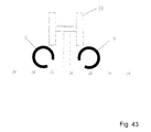
- Fig. 43 shows the use of mats 9 in connection with crash barriers 39.
- the mats 9 are like this arranged that they are a possibility for collecting from the Form vehicles that have strayed from the street. Through the Elasticity of the mats 9 will damage the Vehicles minimized.
- Fig. 44 shows the use of Braids 25 or 9 as mats Traffic control elements and as impact protection in the Road traffic. The elements are next to street 34, primarily in the area of curves.
- Fig. 45 is the use of mats 9 as drainage next to the Street 34 shown. The mats 9 are in present embodiment rolled up and thereby fulfill the drainage function.
- Fig. 46 the mats 9 are used as a fence and serve the Delimitation of areas against humans and animals.
- Fig. 47 shows one Application variant as load-distributing elements.
- the mats 9 come into play when placing loads a load distribution and thereby a reduction the ground pressure.
- they are in 48 shows applications of the mats 9 suitable.
- the trees 41 can pass through on the one hand Mats 9 are sheathed on the trunk, on the other hand can the root area of the tree 41 is covered with mats 9 become.
- Mats 9 as shown in Fig. 49, suitable.
- the Contents of the silo system 42 is covered with mats 9, see above that on the one hand a cover, on the other hand a Weighting results.
- the use of the mats 9 as Landfill limitation is shown in Fig. 50. Either are below and above the landfill body 43 Mats 9 arranged, which the one hand Cover landfill body 43, on the other hand the Landfill body 43 with respect to the surrounding earth delimit. To realize increasing entrances the arrangement of mats according to FIG. 51 is suitable. ever after how the landfill body 43 increased, mats are staggered one above the other.
- a use of the mats 9 as fire mats is in Fig. 52 shown. The mats are laid out and lit to create a backfire. hereby will spread fire, for example at Forest fires, effectively prevented.
- the creation of for example rice fields 44 is used to arrange the 54 mats.
- the use of mats in Desert areas is shown in Fig.
- mats 9 are introduced into the streets or path 34. If there are roadway overpasses, use Metal detector the original course of street 34 can be located by placing the metal detector on the in the Mat metal parts appeals.
- the mats 9 and braid 25 can with the help of Carrier units, for example gas-filled balloon, Helicopter or airship, transported or be stationed. A transport is as in Fig. 56 visible, both in horizontal and in vertical position possible.
- the use of mats 9 and Braided bodies 25 in space are indicated in Fig. 57, where through the mats 9 and braids 25 a Security cage is realized in which Space technology 45 can be arranged.
Abstract
Description
Die Erfindung betrifft ein Verfahren zum Verarbeiten von Reifen und zur Herstellung von aus dem Reifenmaterial bestehenden Produkten in Form von Flächengebilden oder Körpern, beispielsweise Blöcke, Hohlkörper, Matten oder Stränge, welche aus den geschnittenen Reifen hergestellt sind.The invention relates to a method for processing of tires and for the production of from the Tire material existing products in the form of Sheets or bodies, for example blocks, Hollow bodies, mats or strands, which from the cut tires are made.
Die Erfindung ist anwendbar insbesondere zur Umformung von nicht mehr verkehrstechnisch verwertbaren PKW-, LKW- oder Flugzeugreifen in einen neuen Grundbaustein, der als Ausgangsmaterial für die Herstellung von Produkten in vielfältigen Bereichen der Wirtschaft eingesetzt werden kann. Zwischenprodukt für die Herstellung neuer Endprodukte sind aus den Reifen geschnittene Ringe.The invention is applicable in particular for forming of cars that can no longer be used for transport purposes, Truck or airplane tires in a new building block, which as a raw material for the production of Products in diverse areas of the economy can be used. Intermediate for the Manufacturing new end products are out of tires cut rings.
Es ist bekannt, nicht mehr zugelassene Reifen zu zerkleinern, beispielsweise durch Schreddern, und die entstehenden Fragmente als Zuschlagmaterial, beispielsweise zur Zementherstellung oder als Füllstoff im Straβenunterbau, zu verwenden. Weitere Verwendungsmöglichkeiten von Altreifen sind die Verbrennung und damit die Erzeugung von Wärmeenergie, die chemische Auflösung zu Rohprodukten oder die Lagerung auf Deponien.It is known to shred tires that are no longer approved, for example by shredding, and the resulting Fragments as aggregate, for example for cement production or as a filler in the road base, to use. Other uses of used tires are the combustion and thus the Generation of thermal energy, the chemical dissolution too Raw products or storage in landfills.
Nachteilig an den bekannten Verwendungsmöglichkeiten ist, daß diese eine Wiederverwendung nur mit Wert-, Rohstoff- oder Eigenschaftsverlust zulassen. Eine Zentralisierung der Verwendung geht nur über das Transportieren der Reifen mit vollem Volumenumfang.A disadvantage of the known uses is that this reuse only with value, Allow loss of raw material or property. Centralization use is only about transportation the full volume tire.
Die DE 39 33 729 A1 beschreibt ein Verfahren zur Verwertung von Altreifen, wobei die Reifen zerschnitten und zu Endlosbändern zusammengeführt werden. Die Anwendungsgebiete derartiger Endlosbänder sind relativ beschränkt.DE 39 33 729 A1 describes a method for Recycling of old tires, the tires being cut up and be merged into endless belts. The Areas of application of such endless belts are relative limited.
In der DE 33 086 51 A1 wird ein Netzwerk aus reifenförmigen Körpern beschrieben, in welchem die Reifen unzerteilt oder in Ringe oder Streifen geschnitten angeordnet sind.DE 33 086 51 A1 describes a network described tire-shaped bodies, in which the Tires undivided or in rings or strips are arranged cut.
Für die Verbindung von aus Reifen hergestellten Ringen sind zusätzliche Verbindungselemente wie Nieten, Klammern oder Nadeln notwendig .For the Connection of rings made from tires additional connecting elements such as rivets, clamps or needles.
Mit der DE 42 009 49 A1 wird ein Verfahren und eine Vorrichtung zur Zerlegung von Altreifen beschrieben, mit welcher ein fixierter, rotierend angetriebener Reifen durch beweglich angeordnete Messer von außen zerschnitten wird, wodurch die Reifenlauffläche, zwei Steitenwände und zwei Wulstringe anfallen. DE 42 009 49 A1 describes one method and one Device for dismantling old tires described, with which a fixed, rotating driven Tires from outside thanks to movably arranged knives is cut, causing the tire tread, two Steiten walls and two bead rings are incurred.
Der Erfindung liegt daher die Aufgabe zugrunde, ein Verfahren zu schaffen, mit welchem eine effektive Aufarbeitung von verschiedensten Reifen ermöglicht wird und über mit einfachen Mitteln preiswert herstellbare Zwischenprodukte in Form geschnittener Ringe neue Endprodukte mit hohem Verwendungswert geschaffen werden ohne Verwendung zusätzlicher Verbindungselemente.The invention is therefore based on the object To create procedures with which an effective Refurbishment of a wide variety of tires is made possible and about inexpensive to produce with simple means Intermediate products in the form of cut rings new End products with high usage value are created without using additional connecting elements.
Es ist weiterhin Aufgabe der Erfindung, neuartige Anwendungsgebiete und Verwendungen der Endprodukte aufzuzeigen.It is a further object of the invention to create novel ones Areas of application and uses of the end products show.
Diese Aufgabe wird erfindungsgemäß gelöst durch die
Merkmale der Ansprüche 1, 9,10 und
14.
Zweckmäßige Ausgestaltungen der Erfindung sind in den
Unteransprüchen enthalten.This object is achieved according to the invention by the features of
Appropriate embodiments of the invention are contained in the subclaims.
Ein besonderer Vorteil der Erfindung besteht darin, daß die Umformung der Reifen in das Zwischenprodukt Ringe eine vollständig umweltfreundliche Produktionsmethode ist, bei der kein Abfall entsteht und keine Schadstoffe freigesetzt werden, indem die Reifen durch eine Aufeinanderfolge von Schnitten zerlegt werden derart, daß die zwei Seitenteile von der Lauffläche abgetrennt werden und die aus den Seitenteilen und/oder der Lauffläche entstehenden Ringe zu neuen Produkten miteinander verbunden werden. Auch der gummiummantelte Metallring, der den festen Sitz auf der Felge gewährleistet, kann weiterverwertet werden.A particular advantage of the invention is that the transformation of the tires into the intermediate rings a completely environmentally friendly production method where there is no waste and no pollutants be released by the tires through a succession of cuts are cut so that the two side parts are separated from the tread and those from the side parts and / or the tread emerging rings to new products with each other get connected. Even the rubber-coated metal ring, which ensures a tight fit on the rim can be further used.
Alle Reifen, die nicht runderneuert werden können, nicht deformiert sind und nicht in Querrrichtung geteilt worden sind, können für das erfindungsgemäße Verfahren verwendet werden. Das Verfahren ermöglicht für die Reifen eine Umformung am Anfallort.All tires that cannot be retreaded are not deformed and are not divided in the transverse direction have been used for the inventive method be used. The procedure enables for the tires are formed at the point of accumulation.
Ein weiterer Vorteil der Erfindung besteht darin, daß
die Elastizität der Ringe mit den Vorzügen des Reifens
anteilsmäßig erhalten bleibt.
Durch die entstandene Ringform reduzieren sich Fläche
und Volumen der Transportmasse auf Materialvolumen bzw.
Materialwichte. Der Reifen ist in der neuen Form, also
als Ring, so zu transportieren, daß er das vorherige
Volumen eines ganzen Reifens nicht mehr erreicht. Die
entstandenen Ringe sind zwei- und dreidimensional in
jede beliebige Form zu bringen, die der entstandene
Ring zuläßt.
Die Ringe sind in geeigneter Form stapelbar und
transportabel. Werden die Reifen zu einer stationären
Schneidanlage oder auch einer anderen Verwertungsanlage
transportiert, so ist es zur Transportraumeinsparung
vorteilhaft, daß die Reifen einmal entlang der Mitte
der Lauffläche durchschnitten werden derart, daß zwei
U-förmig ausgebildete Reifenteile entstehen, welche
ineinander stapelbar sind.Another advantage of the invention is that the elasticity of the rings is retained proportionately with the advantages of the tire.
The resulting ring shape reduces the area and volume of the transport mass to material volume or material weight. The tire is to be transported in the new form, ie as a ring, in such a way that it no longer reaches the previous volume of an entire tire. The resulting rings are to be made in two and three dimensions in any shape that the resulting ring allows.
The rings can be stacked and transported in a suitable form. If the tires are transported to a stationary cutting system or another recycling system, it is advantageous to save transport space that the tires are cut once along the center of the tread such that two U-shaped tire parts are formed which can be stacked one inside the other.
Die Erfindung soll nachstehend anhand von zumindest teilweise in den Figuren dargestellten Ausführungsbeispielen näher erläutert werden. Es zeigen:
- Fig. 1
- eine stilisierte Darstellung der Schnittführung an einem zur Hälfte dargestellten Reifen,
- Fig. 2
- die Produkte aus der Schnittführung gemäß Fig. 1,
- Fig. 3A
- die Entstehung einer Ringkette,
- Fig. 3B
- die Entstehung eines Geflechtes,
- Fig. 3C
- der Aufbau eines Grundelementes (Viererelement),
- Fig. 3D
- der Aufbau eines Grundelementes (Dreierelement),
- Fig. 3E
- die Entstehung eines Netzes aus Grundelementen gemäß Fig. 3C,
- Fig. 3F
- die Entstehung einer Matte aus Grundelementen gemäß Fig. 3C,
- Fig. 3G
- die Entstehung eines Körpers aus Grundelementen gemäß Fig. 3C,
- Fig. 3H
- die Entstehung eines gewölbten Körpers aus Grundelementen gemäß Fig. 3C,
- Fig. 3K
- einen Ausschnitt aus einer ersten geflochtenen Matte,
- Fig. 3L
- einen geflochtenen Sack,
- Fig. 3M
- einen geflochtenen röhrenförmigen Hohlkörper mit Boden,
- Fig. 3N
- einen Ausschnitt aus einer zweiten geflochtenen Matte,
- Fig. 30
- einen Ausschnitt aus einer dritten geflochtenen Matte,
- Fig. 3P bis Fig. 3U
- weitere Flechtvarianten zur Realisierung von Bausteinen für beispielsweise Stränge, Matten und Körper,
- Fig. 5
- die Anordnung von Körpern zur Realisierung von Matten als Uferschutzmaßnahme
- Fig. 6
- die Anordnung von Matten auf dem Gewässergrund,
- Fig. 7
- die Anordnung von mit Schüttgut gefüllten Hohlkörpern zur Realisierung künstlicher Dämme,
- Fig. 8
- die Anordnung von Körpern zur Realisierung von mit Wasser gefüllten Hohlkörpern zur Realisierung künstlicher Dämme,
- Fig. 9
- eine Dammauskleidung aus geflochtenen Matten,
- Fig. 10
- eine Uferbefestigung aus geflochtenen Matten,
- Fig. 11
- die Realisierung von Faschinen zum Uferschutz,
- Fig. 12
- den Ausgleich von Unebenheiten am Gewässergrund durch Überdecken mit einer Matte,
- Fig. 13
- den Ausgleich von Unebenheiten am Gewässergrund durch Ausfüllen mit Matten,
- Fig. 14
- das Abdecken von Unterwasserriffen mit Matten,
- Fig. 15
- aus Matten realisierte abgegrenzte Räume zur Fischaufzucht,
- Fig. 16
- die Anordnung von Matten zum Schutz von Korallenbänken,
- Fig. 17
- die Anordnung von Matten zum Schutz in Schleusenbecken,
- Fig. 18
- die Anordnung von Matten zum Schutz vor Eiseinbruch,
- Fig. 19
- die Anordnung von Matten in Teichen,
- Fig. 20
- die Anordnung von Matten in Flüssen,
- Fig. 21
- die Anordnung von Matten als Wellenabsorber,
- Fig. 22
- die Anordnung von Flechtkörpern als Wellenbrecher,
- Fig. 23
- die Anordnung von Flechtkörpern als Unterwasserwellenabsorber,
- Fig. 24
- die Anordnung von Flechtkörpern zum Schutz von Kaianlagen,
- Fig. 25
- die Anordnung von Flechtkörpern zum Schutz von Bauwerken,
- Fig. 26
- die Anordnung von Flechtkörpern oder Matten zum Schutz von Brückenpfeilern,
- Fig. 27
- die Anordnung von Flechtkörpern oder Matten zum Schutz von Brückenpfeilern und ähnlichen Bauwerken,
- Fig. 28
- die Anordnung von Flechtkörpern zum Schutz gegen Eisgang,
- Fig. 29
- den Einsatz von Matten oder Flechtkörpern als Filter,
- Fig. 30
- den Einsatz von Matten oder Flechtkörpern als Absturzschutz,
- Fig. 31
- den Einsatz von Matten oder Flechtkörpern als Schutz der Schiffsaußenhaut,
- Fig. 32
- den Einsatz von Matten zur Erdbefestigung,
- Fig. 33
- den Einsatz von Matten als Pflanzenschutz,
- Fig. 34
- den Einsatz von Matten zur Realisierung von Dämmen für Speicherbecken,
- Fig. 35
- den Einsatz von Matten oder Körpern als Lawinenschutz,
- Fig. 36
- den Einsatz von Matten oder Körpern in Fundamenten,
- Fig. 37
- den Einsatz von Matten zur Realisierung von Dämmen für Speicherbecken oder Körpern als Straßenuntergrund,
- Fig. 38
- den Einsatz von Matten als Rohr- bzw. Kabelschacht,
- Fig. 39
- den Einsatz von Matten oder Körpern als Schutzelemente bei Sprengungen,
- Fig. 40
- den Einsatz von Matten zur Verhinderung von Steinschlag,
- Fig. 41
- den Einsatz von Matten oder Körpern zur Realisierung von Schutzbauten in Erdbebengebieten,
- Fig. 42
- den Einsatz von Matten zum Schutz von Bunkerbauwerken,
- Fig. 43
- den Einsatz von Matten in Verbindung mit Leitplanken,
- Fig. 44
- den Einsatz von Matten als Verkehrrsleitelement und Aufprallschutz im Straßenverkehr,
- Fig. 45
- den Einsatz von Matten als Drainage,
- Fig. 46
- den Einsatz von Matten als Zaun,
- Fig. 47
- den Einsatz von Matten als Lastverteilerelement,
- Fig. 48
- den Einsatz von Matten als Baumschutz,
- Fig. 49
- den Einsatz von Matten als Silageabdeckung,
- Fig. 50
- den Einsatz von Matten als Deponiebegrenzung,
- Fig. 51
- den Einsatz von Matten zur Realisierung sich erhöhender Einfahrten,
- Fig. 52
- den Einsatz von Matten als Brandmatte für Gegenfeuer,
- Fig. 53
- den Einsatz von Matten zur Realisierung von Blitzschutz und Unterstellmöglichkeiten,
- Fig. 54
- den Einsatz von Matten zum Anlegen von Reisfeldern,
- Fig. 55
- den Einsatz von Matten zur Fahrbahnmarkierung,
- Fig. 56
- Transportmöglichkeiten für die Matten bzw. Körper,
- Fig. 57
- den Einsatz von Matten zur Realisierung von Sicherheitskäfigen im Weltraum.
- Fig. 1
- a stylized representation of the cut on a half shown tire,
- Fig. 2
- the products from the cut according to FIG. 1,
- Figure 3A
- the creation of a ring chain,
- Figure 3B
- the formation of a network,
- Figure 3C
- the construction of a basic element (four element),
- Fig. 3D
- the construction of a basic element (triple element),
- Figure 3E
- the creation of a network of basic elements according to FIG. 3C,
- Figure 3F
- the formation of a mat from basic elements according to FIG. 3C,
- Fig. 3G
- the formation of a body from basic elements according to FIG. 3C,
- Figure 3H
- the formation of a curved body from basic elements according to FIG. 3C,
- Figure 3K
- a section of a first braided mat,
- Figure 3L
- a braided sack,
- Figure 3M
- a braided tubular hollow body with bottom,
- Figure 3N
- a section of a second braided mat,
- Fig. 30
- a section of a third braided mat,
- 3P to 3U
- further braiding variants for the realization of building blocks for e.g. strands, mats and bodies,
- Fig. 5
- the arrangement of bodies for the realization of mats as a bank protection measure
- Fig. 6
- the arrangement of mats on the water bottom,
- Fig. 7
- the arrangement of hollow bodies filled with bulk material for the realization of artificial dams,
- Fig. 8
- the arrangement of bodies for the realization of hollow bodies filled with water for the realization of artificial dams,
- Fig. 9
- a dam lining made of braided mats,
- Fig. 10
- a bank reinforcement made of braided mats,
- Fig. 11
- the realization of machinery for bank protection,
- Fig. 12
- the compensation of unevenness on the water bottom by covering it with a mat,
- Fig. 13
- the compensation of unevenness on the water floor by filling with mats,
- Fig. 14
- covering underwater reefs with mats,
- Fig. 15
- demarcated spaces for fish farming realized from mats,
- Fig. 16
- the arrangement of mats to protect coral banks,
- Fig. 17
- the arrangement of mats for protection in lock basins,
- Fig. 18
- the arrangement of mats to protect against ice break-in,
- Fig. 19
- the arrangement of mats in ponds,
- Fig. 20
- the arrangement of mats in rivers,
- Fig. 21
- the arrangement of mats as wave absorbers,
- Fig. 22
- the arrangement of braided bodies as a breakwater,
- Fig. 23
- the arrangement of braided bodies as underwater wave absorbers,
- Fig. 24
- the arrangement of braided bodies to protect quay systems,
- Fig. 25
- the arrangement of braided bodies to protect buildings,
- Fig. 26
- the arrangement of braided bodies or mats to protect bridge piers,
- Fig. 27
- the arrangement of braided bodies or mats to protect bridge pillars and similar structures,
- Fig. 28
- the arrangement of braided bodies to protect against ice,
- Fig. 29
- the use of mats or braids as a filter,
- Fig. 30
- the use of mats or wicker as fall protection,
- Fig. 31
- the use of mats or braids to protect the ship's outer skin,
- Fig. 32
- the use of mats for ground fastening,
- Fig. 33
- the use of mats as crop protection,
- Fig. 34
- the use of mats to create dams for storage pools,
- Fig. 35
- the use of mats or bodies as avalanche protection,
- Fig. 36
- the use of mats or bodies in foundations,
- Fig. 37
- the use of mats to create dams for storage basins or bodies as a road surface,
- Fig. 38
- the use of mats as pipe or cable duct,
- Fig. 39
- the use of mats or bodies as protective elements for blasting,
- Fig. 40
- the use of mats to prevent stone chips,
- Fig. 41
- the use of mats or bodies to implement protective structures in earthquake areas,
- Fig. 42
- the use of mats to protect bunker structures,
- Fig. 43
- the use of mats in combination with guardrails,
- Fig. 44
- the use of mats as a traffic control element and impact protection in road traffic,
- Fig. 45
- the use of mats as drainage,
- Fig. 46
- the use of mats as a fence,
- Fig. 47
- the use of mats as a load distribution element,
- Fig. 48
- the use of mats as tree protection,
- Fig. 49
- the use of mats as a silage cover,
- Fig. 50
- the use of mats as landfill limits,
- Fig. 51
- the use of mats to realize increasing entrances,
- Fig. 52
- the use of mats as fire mats for counter-fire,
- Fig. 53
- the use of mats to implement lightning protection and storage facilities,
- Fig. 54
- the use of mats to create rice fields,
- Fig. 55
- the use of mats for lane marking,
- Fig. 56
- Transport options for the mats or body,
- Fig. 57
- the use of mats to create security cages in space.
Wie in Fig. 1 dargestellt, wird ein Reifen derart
geschnitten, daß ein Laufflächenring 1 und zwei
Seitenringe 2 entstehen. Der Laufflächenring 1 und die
Seitenringe 2 sind in Fig. 2 dargestellt.As shown in Fig. 1, a tire becomes like this
cut that a
Der Laufflächenring 1 kann durch weitere Schnitte in
schmalere Ringe zerlegt werden, ebenso die Seitenringe
2.The
Die Herstellung von Flächengebilden bzw. Körpern
erfolgt durch Zusammenführung von Ringen per Hand oder
mittels Handhabungsmanipulatoren oder Griffelementen.
Das Verbindung der Ringe von Hand erfolgt derart, daß
man einen Ring ergreift und diesen so zusammendrückt,
daß links und rechts gleichgroße Schlaufen bzw.
Öffnungen entstehen.
Das Durchführen eines weiteren Ringes durch die beiden
Schlaufen oder Öffnungen im zusammengefalteten Zustand
ermöglicht das Ergreifen der Schlaufen des zweiten
Ringes. Durch Arretieren des Anfangsringes ist ein
Öffnen zu verhindern, so daß durch die entstandenen
Schlaufen ein neuer Ring eingeführt werden kann.
Unterstützt wird dieses Flechten durch Vorrichtungen,
die das entstandene Geflecht von der Anlage so
ableiten, daß ein kontinuierlicher Produktionsprozeß in
der Flechtanlage stattfinden kann.
In Fig. 3A bis 3H sind einige Ausführungsformen von
durch Flechten entstandenen Flächengebilden und Körpern
gezeigt. Sehr effektiv gefertigte Flächengebilde sind
Matten, welche beispielsweise zur Verstärkung von
Deichen gegen Hochwassereinflüsse anwendbar sind.The production of flat structures or bodies takes place by bringing rings together by hand or by means of handling manipulators or grip elements. The rings are connected by hand in such a way that a ring is gripped and pressed together in such a way that loops and openings of the same size are formed on the left and right.
Passing a further ring through the two loops or openings in the folded state enables the loops of the second ring to be gripped. Locking the start ring prevents opening so that a new ring can be inserted through the loops created. This braiding is supported by devices that derive the resulting braid from the system so that a continuous production process can take place in the braiding system.
3A to 3H show some embodiments of sheets and bodies formed by braiding. Mats that are very effectively manufactured are mats, which can be used, for example, to reinforce dikes against flooding.
Die Figur 3A zeigt die Entstehung einer Ringkette, bei welcher die einzelnen Ringe ineinander verknotet sind. Figur 3B zeigt die Entstehung eines Geflechtes. In der Figur 3C ist der Aufbau eines Grundelementes als Viererelement und in der Figur 3E als Dreierelement dargestellt. Die Figur 3E zeigt die Entstehung eines Netzes aus Grundelementen gemäß der Figur 3C. In der Figur 3F ist der Aufbau einer Matte gezeigt, die Figur 3D zeigt einen als Quader ausgebildeten Körper und die Figur 3H die Entstehung eines gewölbten Körpers. In der Figur 3K ist ein Ausschnitt aus einer geflochtenen Matte dargestellt. Die Figur 31 zeigt einen geflochtenen Sack, welcher der Aufnahme von beispielsweise Schüttgut dienen kann. In der Figur 3M ist ein geflochtener röhrenförmiger Hohlkörper dargestellt, welcher mit einem gewölbten Boden verschlossen ist. Die Figur 3N zeigt einen Ausschnitt aus einer zweiten geflochtenen Matte und die Figur 30 einen Ausschnitt aus einer dritten geflochtenen Matte. In den Figuren 3P-3U sind weitere Flechtvarianten zur Realisierung von Bausteinen für beispielsweise Stränge, Matten und Körper gezeigt.Figure 3A shows the formation of a ring chain, at which the individual rings are knotted together. Figure 3B shows the formation of a braid. In the Figure 3C is the construction of a basic element as Four-element and in Figure 3E as a three-element shown. Figure 3E shows the emergence of a Network of basic elements according to Figure 3C. In the Figure 3F shows the structure of a mat, the figure 3D shows a cuboid body and the Figure 3H shows the formation of an arched body. In the Figure 3K is a section of a braided Mat shown. Figure 31 shows one braided sack, which is the inclusion of for example bulk goods can serve. In the figure 3M is a braided tubular hollow body shown, which with a domed bottom is closed. FIG. 3N shows a section from a second braided mat and the figure 30 a section of a third braided mat. In the figures 3P-3U further braiding variants are available Realization of building blocks for e.g. strands, Mats and body shown.
Nachfolgend sollen verschiedenste Anwendungsgebiete von
durch Flechten von geschlossenen Ringen hergestellten
neuen Produkten beschrieben werden. Eine Anwendung ist den
Aufbau von Dämmen, welche in ihrem Inneren gefüllte
Hohlkörper 13 oder Flechtkörper 25 aufweisen. Durch die
Hohlkörper 13, die Flechtkörper 25 oder auch die
Anordnung von Matten 9 erfolgt eine Stabilisierung der
Dammkonstruktion, so daß die Dämme wesentlich höheren
Belastungen standhalten als lediglich aus Erde 15
aufgeschüttete Dämme.Various areas of application of
made by braiding closed rings
new products are described. One application is that
Construction of dams, which filled inside
Have
Figur 5 zeigt die Anordnung von Matten als
Uferschutzmaßnahme, wobei im vorliegenden
Ausführungsbeispiel zwei Matten 9 übereinander
angeordnet sind. Die Matten 9 sind im Ufer 10
eingelassen, und der durch das Wasser 11 erzeugte Druck
verteilt sich über die Matten 9 und schützt das Ufer 10
auch gegen Anschwämmung und Abtragung. Diese
Schutzmaßnahme ist sowohl an Kanälen als auch an
natürlichen Ufern anwendbar.Figure 5 shows the arrangement of mats as
Bank protection measure, whereby in the present
Embodiment two
Die Figur 6 zeigt die Anordnung von Matten 9 auf dem
Gewässergrund 12, wobei durch diese Anordnung ein
Abtragen von beispielsweise Sand und damit die
Entstehung von Ausspühlungen verhindert wird. In der
Figur 7 sind mit Schüttgut, beispielsweise Sand,
gefüllte Hohlkörper 13 dargestellt, welche als
künstliche Dämme im Wasser 11 in beliebiger Länge, Höhe
und Breite aufgestellt werden können. Eine weitere
Realisierungsform von Hohlkörpern 13 ist in Figur 8
dargestellt, wobei hier die Hohlkörper 13 mit Wasser 11
gefüllt sind. Damit das Wasser nicht durch die
Zwischenräume im Flechtwerk ablaufen kann, sind die
Hohlkörper 13 innen mit einer Folie 14 ausgekleidet.Figure 6 shows the arrangement of
In Figur 9 ist eine Dammauskleidung aus geflochtenen
Matten 9 dargestellt, wobei die Dammauskleidung mit
Erde 15 bedeckt ist und der Damm einen Konterschacht
16, welcher ebenfalls durch die Matten 9 ausgekleidet
ist, aufweist. In der Figur 10 ist eine einfache Form
einer Uferbefestigung aus geflochtenen Matten 9
dargestellt, wobei die Matten 9 hier teilweise in das
Wasser 11 sowie die am Ufer 10 befindliche Erde 15
hineinreicht. Figur 11 zeigt die Realisierung von
Faschinen zum Uferschutz, wobei hier die Ringe 1 mit
Pfählen 17 zusammenwirken. In den Figuren 12 und 13 ist
der Ausgleich von Unebenheiten am Gewässergrund
dargestellt. Gemäß dem Ausführungsbeispiel in Figur 12
wird die Unebenheit 18 durch eine Matte 9 abgedeckt, im
Ausführungsbeispiel gemäß Figur 13 wird die Unebenheit
durch Matten 9 ausgefüllt. In der Figur 14 ist das
Abdecken von Unterwasserriffen 19 mit Matten 9
dargestellt. Diese Maßnahme dient dem Schutz von
Wasserfahrzeugen gegen Kollision.In Figure 9 is a dam lining made of braided
Figur 15 zeigt die Realisierung abgegrenzter Räume zur
Fischaufzucht, wobei die Abgrenzung der Räume durch
Matten 9 erfolgt. Im Inneren der durch die Matten 9
begrenzten Räume können Fische effektiv aufgezogen
werden. Figur 16 zeigt die Anordnung von Matten 9 zum
Schutz von Korallenbänken.Figure 15 shows the realization of delimited rooms
Fish farming, the demarcation of the rooms by
In Figur 17 ist ein Anwendungsbeispiel dargestellt, bei
welchem der Innenraum von Schleusenbecken 21 mit Matten
9 ausgekleidet ist. Die Matte 9 kann dazu dienen, um
Schiffe, beispielsweise Sportboote, zu bergen und zu
sichern. In Figur 18 ist die Anwendung der Matten 9 zum
Schutz vor Eiseinbruch dargestellt. Die Matten 9 sind
an Schwimmkörpern 22 befestigt, welche unterhalb der
Wasseroberfläche angeordnet sind. Überfriert nun das
Gewässer mit einer Eisfläche 23, so befindet sich unter
der Eisfläche 23 das Schutzgebilde aus Matten 9 und
Schwimmkörpern 22. Bricht nun eine Person durch die
Eisfläche 23 ein, so wird sie durch die Matten 9 vor
dem Untergehen bzw. dem Ertrinken bewahrt.An application example is shown in FIG
which the interior of
Die Anordnung der Matten 9 gemäß Figur 19 dient der
Entfernung von Unrat in Teichen, beispielsweise in
Feuerwehrteichen, indem die Matten 9 gehoben werden. In
Figur 20 ist eine Anwendung der Matten 9 in Flüssen 24
dargestellt, wobei die Matten 9 am Flußboden angeordnet
sind und diesen auskleiden. Durch die Auskleidung wird
einem Bodenabtrag und einem Sedimentauftrag vorgebeugt. The arrangement of the
Die Figuren 21 bis 23 zeigen die Anordnung von Matten 9
bzw. von Flechtkörpern 25 als Wellenabsorber bzw.
Wellenbrecher. Die Matten 9 bzw. die Flechtkörper 25
sind ganz oder teilweise unter Wasser angeordnet. In
Figur 24 ist ein Ausführungsbeispiel dargestellt, bei
welchem Flechtkörper 25 zum Schutz von Kaianlagen 27
angeordnet sind. Die Flechtkörper 25 können mit
Schwimmkörpern 22 zusammenwirken, auf dem Gewässergrund
12 verankert oder im Gewässergrund 12 eingebunden sein.
In Figur 25 ist allgemein der Schutz von Bauwerken
durch Flechtkörper 25 dargestellt. Anstelle der
Flechtkörper 25 können auch Matten 9 verwendet werden.
Ausgewählte Bauwerke im vorliegenden
Ausführungsbeispiel sind Häuser, welche gegen Berührung
mit einem Bagger geschützt werden oder wasserbauliche
Anlagen, wie Häfen oder Brücken. Der Schutz speziell
von Brückenpfeilern 28 ist in Figur 26 dargestellt,
wobei hier die Brückenpfeiler 28 durch Matten 9
ummantelt sind. Ein weiteres Ausführungsbeispiel zum
Schutz von Brückenpfeilern 28, Stegen und Dämmen vor
Beschädigung ist in Figur 27 dargestellt. Zur Anwendung
gelangen entweder Matten 9, welche mit Schwimmkörpern
zusammenwirken, oder Flechtkörper 25. Die Flechtkörper
25 bzw. die Matten 9 sind vor den Brückenpfeilern 28
angeordnet. Figur 28 zeigt die Anordnung von
Flechtkörpern 25 im Wasser zum Schutz vor Eisgang auf
Flüssen, Seen und Meeren. Durch die Flechtkörper 25
werden die Eismassen abgefangen, so daß Schäden
verhindert werden können. In Figur 29 ist der Einsatz
von Matten 9 oder Flechtkörpern 25 als Filter
dargestellt. So können beispielsweise die Matten 9 von
einem Schiff 31 durch das Wasser 11 gezogen werden, um
Verunreinigungen durch die Netzstruktur der Matten 9
abzufischen. Ebenso ist es möglich in Kläranlagen 29
Matten 9 einzubringen, welche Verunreinigungen
herausfischen. Eine weitere Anwendungsmöglichkeit der
Matten 9 besteht darin, diese vor dem Einlauf von
Sammelbecken anzuordnen, so daß Verunreinigungen
herausgefiltert werden. In Figur 30 ist die Anordnung
von Matten 9 bzw. von Flechtkörpern 25 als aktiver
Personen- und Tierschutz dargestellt. Die Matten 9 bzw.
die Flechtkörper 25 beugen möglichen Abstürzen vor. Die
Anordnung von Matten 9 an der Außenhaut eines Schiffes
31 schützt die Schiffsaußenwand vor mechanischen
Beschädigungen. Der Einsatz von Matten 9 für
Erdbefestigungen ist in Figur 32 dargestellt. Ein
spezielles Anwendungsgebiet ist die Abhangbefestigung,
wobei hier sowohl eine einzelne Matte 9 oder mehrere
übereinander angeordnete Matten 9 eingesetzt werden
können. In Figur 33 ist die Anwendung von Matten 9 als
Pflanzenschutz dargestellt. Die Erdfläche 15 ist mit
Matten 9 belegt, und in die durch das Flechtwerk
gebildeten Zwischenräume werden Pflanzen 32
angepflanzt. Figur 34 zeigt den Einsatz von Matten 9
zur Realisierung von Dämmen und Speicherbecken. Ein
spezielles Anwendungsgebiet ist der Bau von
Auffangbecken für Wasser aus Hochwasser führenden
Flüssen. Die Matte 9 ist in einen Graben eingelegt und
stabilisiert den Damm des Speicherbeckens. Anstelle der
Realisierung von Speicherbecken können die mittels der
Matten 9 stabilisierten Dämme auch zur Realisierung von
Salzgewinnungsbecken dienen. Die Figur 35 zeigt die
Anwendung von Matten 9 oder Flechtkörpern 25 als
Lawinenschutz. Die Matten 9 bzw. die Flechtkörpern 25
sind am Hang 33 angeordnet und dienen dem Abfangen von
Lawinen. Figur 36 zeigt die Verwendung von Matten 9
oder Flechtkörpern 25 in Fundamenten. Es ist möglich,
durch die Matten 9 bzw. die Flechtkörper 25 sowohl
Streifenfundamente als auch vollflächige Fundamente zu
stabilisieren. In Figur 37 ist die Anordnung von Matten
9 als Straßenuntergrund dargestellt. Die Matten 9
werden unter der Straße 34 angeordnet. Anstelle von
Straßen 34 sind selbstverständlich auch Wege und
Plätze, insbesondere Sportplätze, in ihrem Untergrund
durch die Matten 9 stabilisierbar. Figur 38 zeigt die
Anwendung von Matten 9 als Rohr- bzw. Kabelschacht. Die
Rohre 35 bzw. die Kabel 36 werden durch die Matten 9
eingebettet und gegebenenfalls überlappend abgedeckt.
In der Figur 39 ist die Anwendung der Matten 9 bzw. der
Flechtkörper 25 als Schutzelemente bei Sprengungen
dargestellt. So können die Matten 9 Bombenschutzmatten
realisieren oder für den Einsatz zur Sprengung von
Fundmunition angeordnet werden. Weiterhin ist es
möglich, Flechtkörper 25, versetzt angeordnet, als
Schutzelemente bei Spengarbeiten einzusetzen. Um den
Evakuierungsradius beim Bergen von Bomben einzugrenzen
bzw. die Splitterwirkung bei Sprengungen zu minimieren,
können Bomben oder sonstige Fundmunition durch Matten 9
und/oder Flechtkörper 25 abgedeckt werden.FIGS. 21 to 23 show the arrangement of
Der Verhinderung von Steinschlag dient die Anordnung
von Matten 9, wie in Figur 40 dargestellt. Die
Verwendung von Matten 9 oder Flechtkörpern 25 zur
Realisierung von Schutzbauten, beispielsweise in
Erdbebengebieten, ist in Figur 41 dargestellt. Durch
die Matten 9 bzw. die Flechtkörper 25 können
Unterstände, oder wie in Figur 42 gezeigt, Bunkerbauten
38 realisiert werden. Bei den Bunkerbauten 38 können
die Außenflächen durch Matten 9 gedämmt werden. Ebenso
können durch die Matten 9 bzw. die Flechtkörper 25
Unterstellmöglichkeiten im Gebirge realisiert werden,
welche auch einen Blitzschutz bieten. Dies resultiert
daraus, daß durch die Metallbestandteile im Flechtwerk
ein faradayscher Käfig realisiert wird.The arrangement serves to prevent stone chips
of
Fig. 43 zeigt den Einsatz von Matten 9 in Verbindung
mit Leitplanken 39. Hier sind die Matten 9 derart
angeordnet, daß sie eine Auffangmöglichkeit für von der
Straße abgekommene Fahrzeuge bilden. Durch die
Elastizität der Matten 9 werden Beschädigungen an den
Fahrzeugen minimiert. Fig. 44 zeigt den Einsatz von
Flechtkörpern 25 bzw. von Matten 9 als
Verkehrsleitelemente und als Aufprallschutz im
Straßenverkehr. Die Elemente sind neben der Straße 34,
vorrangig im Bereich von Kurven, angeordnet. In Fig. 45
ist die Verwendung von Matten 9 als Drainage neben der
Straße 34 dargestellt. Die Matten 9 sind im
vorliegenden Ausführungsbeispiel eingerollt und
erfüllen hierdurch die Drainagefunktion. In Fig. 46
sind die Matten 9 als Zaun eingesetzt und dienen der
Abgrenzung von Gebieten gegen Mensch und Tier. Auch
gegen Schneeverwehungen oder andersartige Verwehungen,
beispielsweise in der Nähe von Mülldeponien, sind
derartige Zäune anwendbar. Fig. 47 zeigt eine
Anwendungsvariante als lastverteilende Elemente. Durch
die Matten 9 kommt es beim Aufsetzen von Lasten zu
einer Lastverteilung und dadurch zu einer Verminderung
des Bodendruckes. Zum Schutz von Bäumen sind die in
Fig. 48 dargestellten Anwendungsfälle der Matten 9
geeignet. So können die Bäume 41 einerseits durch
Matten 9 am Stamm ummantelt werden, andererseits kann
der Wurzelbereich des Baumes 41 mit Matten 9 belegt
werden. Zur Abdeckung von Silage ist die Anwendung der
Matten 9, wie in Fig. 49 dargestellt, geeignet. Der
Inhalt der Siloanlage 42 wird mit Matten 9 belegt, so
daß einerseits eine Abdeckung, andererseits eine
Beschwerung resultiert. Der Einsatz der Matten 9 als
Deponiebegrenzung ist in Fig. 50 dargestellt. Sowohl
unterhalb als auch oberhalb des Deponiekörpers 43 sind
Matten 9 angeordnet, welche einerseits den
Deponiekörper 43 abdecken, andererseits den
Deponiekörper 43 gegenüber dem umgebenden Erdreich
abgrenzen. Zur Realisierung sich erhöhender Einfahrten
ist die Anordnung von Matten gemäß Fig. 51 geeignet. Je
nachdem, wie sich beispielsweise der Deponiekörper 43
erhöht, werden Matten versetzt übereinander angeordnet.
Eine Verwendung der Matten 9 als Brandmatten ist in
Fig. 52 dargestellt. Die Matten werden ausgelegt und
angezündet, um ein Gegenfeuer zu erzeugen. Hierdurch
wird das übergreifen von Feuer, beispielsweise bei
Waldbränden, wirksam verhindert. Dem Anlegen von
beispielsweise Reisfeldern 44 dient die Anordnung der
Matten 9 gemäß Fig. 54. Die Verwendung von Matten in
Wüstengebieten ist in Fig. 55 dargestellt, wo Matten 9
in den Straßen bzw. Wegeverlauf 34 eingebracht sind.
Kommt es zur Fahrbahnüberwehungen so kann mittels
Metalldetektor der ursprüngliche Verlauf der Straße 34
geortet werden, indem der Metalldetektor auf die in den
Matten befindlichen Metallteile anspricht. Die Matten 9
und Flechtkörper 25 können mit Hilfe von
Trägereinheiten beispielsweise gasgefüllter Ballon,
Hubschrauber oder Luftschiff, transportiert bzw.
stationiert werden. Ein Transport ist, wie aus Fig. 56
ersichtlich, sowohl in waagerechter als auch in
senkrechter Lage möglich. Der Einsatz von Matten 9 und
Flechtkörpern 25 im Weltraum ist in Fig. 57 angedeutet,
wo durch die Matten 9 bzw. Flechtkörper 25 ein
Sicherheitskäfig realisiert wird, in welchem
Weltraumtechnik 45 anordenbar ist. 43 shows the use of
Die Erfindung ist nicht beschränkt auf die hier dargestellten Ausführungsbeispiele. Vielmehr ist es möglich, durch Kombination und Modifikation der genannten Mittel und Merkmale weitere Ausführungsvarianten zu realisieren, ohne den Rahmen der Erfindung zu verlassen. The invention is not limited to those shown here Embodiments. Rather, it is possible by combining and modifying the means mentioned and features to realize further design variants, without leaving the scope of the invention.
- 11
- Laufflächetread
- 22
- Seitenringeside rings
- 33
- Reifentires
- 99
- Mattemat
- 1010
- Ufershore
- 1111
- Wasserwater
- 1212
- Gewässergrundbody of water
- 1313
- Hohlkörperhollow body
- 1414
- Foliefoil
- 1515
- Erdeearth
- 1616
- Konterschachtcounter shaft
- 1717
- Pfahlstake
- 1818
- Unebenheitunevenness
- 1919
- Riffreef
- 2020
- Fischefish
- 2121
- Schleusenbeckenlock basin
- 2222
- Schwimmkörperfloat
- 2323
- Eisflächeice surface
- 2424
- FlußFlow
- 2525
- Flechtkörperbraided
- 2626
- Wellenwaves
- 2727
- Kaianlagewharfage
- 2828
- Brückenpfeilerbridge abutment
- 2929
- Kläranlagesewage plant
- 3030
- Einlaufenema
- 3131
- Schiffship
- 3232
- Pflanzenplants
- 3333
- Hanghillside
- 3434
- Straßeroad
- 3535
- Rohr pipe
- 3535
- Rohrpipe
- 3636
- Kabelelectric wire
- 3737
- Erdspaltecrevice
- 3838
- Bunkerbunker
- 3939
- Leitplankebarrier
- 4040
- Lastload
- 4141
- Baumtree
- 4242
- Siloanlagesilo
- 4343
- Deponiekörperlandfill
- 4444
- ReisfelderRice fields
- 4545
- WeltraumtechnikSpace Technology
Claims (14)
- Method for processing tires and the manufacture of products composed of the tire material wherein the tires are dismembered by a sequence of cuts,
characterized in that
the two side walls are separated from the running tread and the rings arising are combined together to new products by means of a weaving process. - Method according to claim 1,
characterized in that
the new products are interwoven mesh surface structures or bodies. - Method according to claim 2,
characterized in that
the interwoven mesh surface structures are mats or aligned units and the bodies are three-dimensional blocks or hollow bodies. - Method according to claim 1,
characterized in that
narrower rings of equal diameter are generated from further cuts along the circumference of the ring produced from the running tread. - Method according to claim 1,
characterized in that
narrower rings of varying diameter are generated from further cuts along the circumference of the ring produced from the side walls. - Method according to at least one of the claims 1 to 5,
characterized in that
production of the individual rings is carried out by means of permanently installed cutting facilities or by means of mobile cutting facilities. - Method according to claim 6,
characterized in that
the tires are cut with a single cut along the middle of the running tread in such a way that two U-shaped tire parts result which can be stacked inside each other for the purpose of their transportation to the permanent cutting facilities. - Method according to claim 1,
characterized in that
the rubber is kept under tension during the process of cutting. - Block, hollow body, mat or aligned units consist of interwoven rings from cut up tires.
- Method for producing the products block, hollow body, mat or aligned units according to claim 9,
characterized in that
for the purpose of interweaving the rings, the initial ring is pressed together in such a way that approximately equal size loops are formed to the left and right and that a further ring is fed through both of these loops such that the ring fed through forms two further loops. - Method according to claim 10,
characterized in that
the external ring and/or end ring is prevented from opening by means of fixation. - Method for producing the products block, hollow body, mat or aligned units according to claim 10,
characterized in that
the interweaving is carried out manually or by a machine. - Method according to claim 12,
characterized in that
the interweaving process for blocks mats or aligned units is carried out at the place of deployment. - The use of mats, hollow bodies, blocks or aligned units produced by interweaving rings according to claim 3 for the construction of dam reinforcement and/or bank protection measures and/or treatment of the beds of bodies of water and/or artificial dams and/or protective measures on reefs and coral banks and/or fish breeding measures and/or recovery measures in sluice locks or pools and/or protective measures against breaking through ice sheets and/or wave protection measures and/or collision protective measures close to building structures and/or filtration or cleaning functions and/or earth consolidation and/or plant protective measures and/or avalanche or falling rock protective measures and/or substrate consolidation in foundations, roads and open spaces and/or cable or pipe shafts and/or explosion protective elements and/or shelters and/or traffic guidance elements and/or tree protective measures and/or drainage functions and/or demarcations and/or load redistribution elements and or silage covers and/or landfill demarcations and or fire mats and/or roadway marking and/or agricultural areas.
Priority Applications (1)
| Application Number | Priority Date | Filing Date | Title |
|---|---|---|---|
| EP20020090165 EP1238771B1 (en) | 1997-09-10 | 1998-09-10 | Device for processing tires |
Applications Claiming Priority (3)
| Application Number | Priority Date | Filing Date | Title |
|---|---|---|---|
| DE19740413A DE19740413C2 (en) | 1997-09-10 | 1997-09-10 | Method and device for processing tires |
| DE19740413 | 1997-09-10 | ||
| PCT/DE1998/002758 WO1999012717A2 (en) | 1997-09-10 | 1998-09-10 | Method and device for processing tires |
Related Child Applications (1)
| Application Number | Title | Priority Date | Filing Date |
|---|---|---|---|
| EP20020090165 Division EP1238771B1 (en) | 1997-09-10 | 1998-09-10 | Device for processing tires |
Publications (2)
| Publication Number | Publication Date |
|---|---|
| EP1011944A2 EP1011944A2 (en) | 2000-06-28 |
| EP1011944B1 true EP1011944B1 (en) | 2003-05-02 |
Family
ID=7842326
Family Applications (2)
| Application Number | Title | Priority Date | Filing Date |
|---|---|---|---|
| EP20020090165 Expired - Lifetime EP1238771B1 (en) | 1997-09-10 | 1998-09-10 | Device for processing tires |
| EP19980945077 Expired - Lifetime EP1011944B1 (en) | 1997-09-10 | 1998-09-10 | Method and device for processing tires |
Family Applications Before (1)
| Application Number | Title | Priority Date | Filing Date |
|---|---|---|---|
| EP20020090165 Expired - Lifetime EP1238771B1 (en) | 1997-09-10 | 1998-09-10 | Device for processing tires |
Country Status (24)
| Country | Link |
|---|---|
| US (2) | US6670003B1 (en) |
| EP (2) | EP1238771B1 (en) |
| JP (1) | JP2002506745A (en) |
| KR (1) | KR100575263B1 (en) |
| CN (1) | CN1195614C (en) |
| AT (1) | ATE238893T1 (en) |
| AU (1) | AU748536B2 (en) |
| BG (1) | BG64146B1 (en) |
| BR (1) | BR9815638A (en) |
| CA (1) | CA2303130C (en) |
| CZ (1) | CZ298297B6 (en) |
| DE (3) | DE19740413C2 (en) |
| DK (1) | DK1011944T3 (en) |
| EA (1) | EA001511B1 (en) |
| ES (1) | ES2201531T3 (en) |
| HU (1) | HUP0003696A3 (en) |
| IL (2) | IL134999A0 (en) |
| NO (1) | NO322692B1 (en) |
| NZ (1) | NZ503748A (en) |
| PL (2) | PL187864B1 (en) |
| PT (1) | PT1011944E (en) |
| SK (1) | SK286045B6 (en) |
| TR (2) | TR200100263T2 (en) |
| WO (1) | WO1999012717A2 (en) |
Families Citing this family (15)
| Publication number | Priority date | Publication date | Assignee | Title |
|---|---|---|---|---|
| DE59905734D1 (en) | 1998-01-19 | 2003-07-03 | Renate Streuer | ELEMENT FROM A MULTIPLE NUMBER OF STRIPES LEVELING HORIZONTALLY AND VERTICAL AND METHOD FOR PRODUCING ELEMENTS BY LINKING CLOSED RINGS |
| FR2795053A1 (en) * | 1999-06-18 | 2000-12-22 | Daniel Rambeau | An elastic fastener for use in packaging of oysters, crustaceans, etc has longitudinally cut loop in flattened chamber of used air |
| FR2798090A1 (en) * | 1999-09-08 | 2001-03-09 | Recyclage Et Technologie | Recycling procedure for large tyres uses high-pressure water jets to cut off tyre walls before removing tread |
| ATE285878T1 (en) * | 1999-09-08 | 2005-01-15 | Recyclage Et Technologie | METHOD AND DEVICE FOR REUSING TIRES |
| EP1246716A1 (en) * | 1999-12-30 | 2002-10-09 | Brian Peter Dunn | Cutting apparatus for motor vehicle tyres |
| RU2184035C2 (en) | 2000-08-31 | 2002-06-27 | Набок Александр Андреевич | Method for grinding of worn-out tires, device and compact pack for its embodiment |
| GB0111129D0 (en) * | 2001-05-05 | 2001-06-27 | Greenlees Alexander | Tyre cutter |
| CN100366512C (en) * | 2005-01-06 | 2008-02-06 | 刘润强 | Tray and its producing method |
| RU2473422C1 (en) * | 2011-07-25 | 2013-01-27 | Федеральное государственное бюджетное образовательное учреждение высшего профессионального образования "Ярославский государственный технический университет" | Method of cutting tires |
| US9144916B2 (en) * | 2012-02-10 | 2015-09-29 | Eagle International, Llc | System and method of removing beads from tires |
| GB2549129A (en) * | 2016-04-06 | 2017-10-11 | Baddeley Tim | A tyre cutting machine and a method of separating a tread of a pneumatic tyre from sidewalls of the pneumatic tyre |
| CN106113118A (en) * | 2016-07-01 | 2016-11-16 | 成都佼佼胶粘制品有限公司 | A kind of sebific duct process equipment |
| US10590616B1 (en) * | 2016-10-14 | 2020-03-17 | Jon Kodi | Protective barrier and a corresponding structure |
| WO2019051186A1 (en) * | 2017-09-08 | 2019-03-14 | Technical Rubber Company, Inc. | Tire downsizing apparatus and method |
| US11753783B2 (en) | 2020-03-24 | 2023-09-12 | Jon Kodi | Guard rail barrier from recycled tires |
Family Cites Families (39)
| Publication number | Priority date | Publication date | Assignee | Title |
|---|---|---|---|---|
| DE7205821U (en) * | 1972-06-08 | Bihr H | Device for cutting car tires lengthways | |
| US1145654A (en) * | 1914-02-02 | 1915-07-06 | David W Anderson | Method of making convexed or concaved bodies of felt or other flexible substances. |
| US1628817A (en) * | 1925-02-14 | 1927-05-17 | Goodrich Co B F | Tire-trimming machine |
| US2230302A (en) * | 1935-11-20 | 1941-02-04 | Goodrich Co B F | Apparatus for removing bead cores from tires |
| US3460419A (en) * | 1967-08-30 | 1969-08-12 | Applied Power Ind Inc | Tire cutting apparatus |
| US3701296A (en) * | 1971-02-18 | 1972-10-31 | James A Snow | Apparatus for cutting strips from vehicle tires |
| US4012973A (en) * | 1975-09-22 | 1977-03-22 | Tiregon, Inc. | Tire cutting apparatus |
| US4096772A (en) * | 1975-09-26 | 1978-06-27 | Walter Dennis Hall | Tire slitting apparatus |
| DE2546430C2 (en) * | 1975-10-16 | 1977-12-01 | Döring, Erich, 8052 Moosburg | Embankment protection from old car tires |
| US4126171A (en) * | 1976-09-20 | 1978-11-21 | Bandag Incorporated | Tire shoulder trimming device |
| US4072072A (en) * | 1977-03-15 | 1978-02-07 | Harb Mitchell A | Dual tire cutting machine |
| JPS55233A (en) * | 1978-06-19 | 1980-01-05 | Kimura Jidosha Kogyo Kk | Disposal of old tire |
| US4450738A (en) * | 1981-09-08 | 1984-05-29 | Tupper Myron D | Tire splitting apparatus |
| JPS5863433A (en) * | 1981-10-13 | 1983-04-15 | Takehiko Sakamoto | Device for cutting rubber tyre or other toroidal substance in round slices |
| DE3308651A1 (en) * | 1983-03-11 | 1984-09-13 | Bauer, Gotthart, 7022 Leinfelden-Echterdingen | Network consisting of tyre-shaped bodies |
| US4946308A (en) * | 1986-09-22 | 1990-08-07 | Chevalier Donald M | Erosion-control matting and method for making same |
| US4682522A (en) * | 1986-10-29 | 1987-07-28 | Barclay Randel L | Shearing method and machine for segmenting scrap tires |
| US4801217A (en) * | 1986-11-24 | 1989-01-31 | Jerry Goldberg | Construction mat formed from discarded tire beads and method for its use |
| US4770077A (en) * | 1987-07-24 | 1988-09-13 | Garmater Robert A | Tire debeader |
| DE3829615A1 (en) * | 1987-10-12 | 1990-03-15 | Juergen Dipl Ing Unterlaender | Plant half-shell mats comprising old tyres |
| US4873759A (en) * | 1988-05-25 | 1989-10-17 | Nu-Tech Systems, Inc. | Tire debeading machine |
| JP2662981B2 (en) * | 1988-06-06 | 1997-10-15 | リンテック株式会社 | Slitter device |
| US5054351A (en) * | 1989-04-27 | 1991-10-08 | Mrp Recycling Technologies Inc. | Tire splitter |
| DE3933729A1 (en) * | 1989-10-09 | 1991-04-18 | Hessenberger Herbert | Methods of re-utilising scrap tyres - by mounting tyre on its beads, rotating it, applying one or more cutters to turn off corresp. strips and joining these end to end |
| US5044057A (en) * | 1990-08-06 | 1991-09-03 | Robert Meagher | Apparatus for making blasting mats |
| ATE170443T1 (en) * | 1991-06-13 | 1998-09-15 | Southern Rubber Pty Ltd | METHOD FOR RECOVERING RUBBER FROM WASTE TIRES |
| DE4200949C2 (en) * | 1992-01-16 | 1994-09-01 | Kurt Seume Spezialmaschinenbau | Device for dismantling used motor vehicle tires |
| US5235888A (en) * | 1992-05-12 | 1993-08-17 | Dom Thomas G | Tire sidewall cutting machine |
| US5590838A (en) * | 1992-07-06 | 1997-01-07 | Garb Oil & Power Corporation | Apparatus and method for reducing vehicle tires to particles |
| JP2990399B2 (en) * | 1992-09-01 | 1999-12-13 | 保 五十嵐 | Manufacturing method of tire mat |
| JPH09503965A (en) * | 1993-10-25 | 1997-04-22 | レーダーバウアー ヴォルフガング | Device for producing tire sectors connected from each other in the area of the tread from the tire |
| US5601004A (en) * | 1994-09-23 | 1997-02-11 | Queen; David A. | Tire cutting apparatus |
| US5443567A (en) * | 1994-10-20 | 1995-08-22 | Pruett; Kearney L. | Tire carcass shredding method and apparatus |
| US5981217A (en) * | 1995-12-11 | 1999-11-09 | Mayo Foundation For Medical Education And Research | DNA encoding TGF-β inducible early factor-1 (TIEF-1), a gene expressed by osteoblasts |
| NO302079B1 (en) * | 1995-12-14 | 1998-01-19 | Ragnar Lotsberg | Mat of used car tires, especially for road surfaces |
| AU4381096A (en) * | 1996-01-18 | 1997-08-11 | Ilia Stoilkov Haralampiev | Process for mechanical breaking of used tyre casings and process equipment |
| US5709049A (en) * | 1996-04-22 | 1998-01-20 | Baird; Donald L. | Ground cover and method of making |
| US5783035A (en) * | 1997-01-21 | 1998-07-21 | Pederson; Les H. | Tire debeading machine |
| US5894997A (en) * | 1997-10-21 | 1999-04-20 | Chen; Ping Lu | Machine for shredding a discarded tire |
-
1997
- 1997-09-10 DE DE19740413A patent/DE19740413C2/en not_active Expired - Fee Related
-
1998
- 1998-09-10 TR TR200100263T patent/TR200100263T2/en unknown
- 1998-09-10 PT PT98945077T patent/PT1011944E/en unknown
- 1998-09-10 HU HU0003696A patent/HUP0003696A3/en unknown
- 1998-09-10 EP EP20020090165 patent/EP1238771B1/en not_active Expired - Lifetime
- 1998-09-10 AT AT98945077T patent/ATE238893T1/en not_active IP Right Cessation
- 1998-09-10 CZ CZ20000816A patent/CZ298297B6/en not_active IP Right Cessation
- 1998-09-10 DE DE59812399T patent/DE59812399D1/en not_active Expired - Fee Related
- 1998-09-10 DK DK98945077T patent/DK1011944T3/en active
- 1998-09-10 JP JP2000510584A patent/JP2002506745A/en active Pending
- 1998-09-10 CA CA 2303130 patent/CA2303130C/en not_active Expired - Fee Related
- 1998-09-10 PL PL36110498A patent/PL187864B1/en not_active IP Right Cessation
- 1998-09-10 PL PL98339434A patent/PL186997B1/en not_active IP Right Cessation
- 1998-09-10 US US09/508,317 patent/US6670003B1/en not_active Expired - Fee Related
- 1998-09-10 WO PCT/DE1998/002758 patent/WO1999012717A2/en active IP Right Grant
- 1998-09-10 KR KR20007002547A patent/KR100575263B1/en not_active IP Right Cessation
- 1998-09-10 IL IL13499998A patent/IL134999A0/en not_active IP Right Cessation
- 1998-09-10 AU AU92536/98A patent/AU748536B2/en not_active Ceased
- 1998-09-10 BR BR9815638A patent/BR9815638A/en not_active IP Right Cessation
- 1998-09-10 NZ NZ50374898A patent/NZ503748A/en unknown
- 1998-09-10 DE DE59808187T patent/DE59808187D1/en not_active Expired - Fee Related
- 1998-09-10 SK SK342-2000A patent/SK286045B6/en not_active IP Right Cessation
- 1998-09-10 EA EA200000296A patent/EA001511B1/en not_active IP Right Cessation
- 1998-09-10 EP EP19980945077 patent/EP1011944B1/en not_active Expired - Lifetime
- 1998-09-10 CN CNB988098563A patent/CN1195614C/en not_active Expired - Fee Related
- 1998-09-10 TR TR200000704T patent/TR200000704T2/en unknown
- 1998-09-10 ES ES98945077T patent/ES2201531T3/en not_active Expired - Lifetime
-
2000
- 2000-03-09 NO NO20001233A patent/NO322692B1/en not_active IP Right Cessation
- 2000-04-06 BG BG104304A patent/BG64146B1/en unknown
-
2003
- 2003-07-21 IL IL157034A patent/IL157034A/en not_active IP Right Cessation
- 2003-10-21 US US10/690,191 patent/US20040107811A1/en not_active Abandoned
Also Published As
Similar Documents
| Publication | Publication Date | Title |
|---|---|---|
| EP1011944B1 (en) | Method and device for processing tires | |
| EP1009883B1 (en) | Dike module | |
| RU2651591C1 (en) | Volumetric gabion structure | |
| EP1012402B1 (en) | Method for securing, stabilising and recovering areas of land and subsoil above and below water | |
| EP3380678A1 (en) | Protective device | |
| AT352639B (en) | SHORE SHORING | |
| EP0952259B1 (en) | Device for preventing flood and erosion damage | |
| DE102013105416B3 (en) | Mobile in its form flexible protective device for explosive ordnance disposal as well as methods for the controlled detonation of an explosive device | |
| DE7604627U1 (en) | OIL LOCK | |
| EP1911885B1 (en) | Erosion protection mattress | |
| DE19510702A1 (en) | Embankment and other large body construction manufacturing method | |
| DE3308651A1 (en) | Network consisting of tyre-shaped bodies | |
| DE10313974B4 (en) | Earth wall with grass cover, in particular dike | |
| RU178536U1 (en) | GABION DESIGN | |
| DE202006015421U1 (en) | Erosion protection mattress, has geo plastic structure provided so that invertebrates and/or invertebrate/aquatische insects penetrate, and geological substrate with chips and stones, where mattress is divided into longitudinal compartments | |
| DE10257603A1 (en) | Device especially for floodwater protection comprises a flexible tube body filled with a fluid, especially water, and/or a fluid/solid mixture | |
| DE2700400A1 (en) | Protection fence for pylons in high flood risk areas - has posts around which is wound wire which is then stretched to give preload | |
| DE19752794A1 (en) | Process for securing, consolidating and regaining soil and subsoil above and under water | |
| DE4220746A1 (en) | Protection of banks and underwater embankments to a depth of approximately 100 m - involves laying of several wire netting strips of customary width to form netting mat. | |
| DEH0015665MA (en) | ||
| DE102006047678A1 (en) | Erosion protection mattress for river bed below e.g. bridge, has upper layer with rough three dimensional structure such as wire of non-plastic filaments, where mattress is divided into longitudinal compartments |
Legal Events
| Date | Code | Title | Description |
|---|---|---|---|
| PUAI | Public reference made under article 153(3) epc to a published international application that has entered the european phase |
Free format text: ORIGINAL CODE: 0009012 |
|
| 17P | Request for examination filed |
Effective date: 20000407 |
|
| AK | Designated contracting states |
Kind code of ref document: A2 Designated state(s): AT BE CH CY DE DK ES FI FR GB GR IE IT LI LU MC NL PT SE |
|
| AX | Request for extension of the european patent |
Free format text: LV PAYMENT 20000407;RO PAYMENT 20000407 |
|
| RAX | Requested extension states of the european patent have changed |
Free format text: LT PAYMENT 20000407;LV PAYMENT 20000407;RO PAYMENT 20000407 |
|
| 17Q | First examination report despatched |
Effective date: 20000905 |
|
| GRAG | Despatch of communication of intention to grant |
Free format text: ORIGINAL CODE: EPIDOS AGRA |
|
| GRAG | Despatch of communication of intention to grant |
Free format text: ORIGINAL CODE: EPIDOS AGRA |
|
| GRAH | Despatch of communication of intention to grant a patent |
Free format text: ORIGINAL CODE: EPIDOS IGRA |
|
| GRAH | Despatch of communication of intention to grant a patent |
Free format text: ORIGINAL CODE: EPIDOS IGRA |
|
| GRAA | (expected) grant |
Free format text: ORIGINAL CODE: 0009210 |
|
| AK | Designated contracting states |
Designated state(s): AT BE CH CY DE DK ES FI FR GB GR IE IT LI LU MC NL PT SE |
|
| AX | Request for extension of the european patent |
Extension state: LT LV RO |
|
| REG | Reference to a national code |
Ref country code: GB Ref legal event code: FG4D Free format text: NOT ENGLISH |
|
| REG | Reference to a national code |
Ref country code: CH Ref legal event code: EP |
|
| REF | Corresponds to: |
Ref document number: 59808187 Country of ref document: DE Date of ref document: 20030605 Kind code of ref document: P |
|
| REG | Reference to a national code |
Ref country code: IE Ref legal event code: FG4D Free format text: GERMAN |
|
| REG | Reference to a national code |
Ref country code: DK Ref legal event code: T3 |
|
| REG | Reference to a national code |
Ref country code: SE Ref legal event code: TRGR |
|
| REG | Reference to a national code |
Ref country code: GR Ref legal event code: EP Ref document number: 20030402999 Country of ref document: GR |
|
| REG | Reference to a national code |
Ref country code: PT Ref legal event code: SC4A Free format text: AVAILABILITY OF NATIONAL TRANSLATION Effective date: 20030801 |
|
| GBT | Gb: translation of ep patent filed (gb section 77(6)(a)/1977) | ||
| PLBQ | Unpublished change to opponent data |
Free format text: ORIGINAL CODE: EPIDOS OPPO |
|
| PLBI | Opposition filed |
Free format text: ORIGINAL CODE: 0009260 |
|
| ET | Fr: translation filed | ||
| REG | Reference to a national code |
Ref country code: ES Ref legal event code: FG2A Ref document number: 2201531 Country of ref document: ES Kind code of ref document: T3 |
|
| PLAX | Notice of opposition and request to file observation + time limit sent |
Free format text: ORIGINAL CODE: EPIDOSNOBS2 |
|
| 26 | Opposition filed |
Opponent name: STREUER, RENATE Effective date: 20040202 |
|
| RAP2 | Party data changed (patent owner data changed or rights of a patent transferred) |
Owner name: SIMON ENERGIEANLAGEN GMBH & CO PROLOOPPATENTVE |
|
| RIN2 | Information on inventor provided after grant (corrected) |
Inventor name: SIMON ENERGIEANLAGEN GMBH & CO PROLOOPPATENTVE |
|
| NLR1 | Nl: opposition has been filed with the epo |
Opponent name: STREUER, RENATE |
|
| REG | Reference to a national code |
Ref country code: CH Ref legal event code: PUE Owner name: SIMON ENERGIEANLAGEN GMBH & CO PRO LOOP PATENTVER Free format text: SCHMELING, BURKHARD#AM MARIENBERG 18#15344 STRAUSBERG (DE) -TRANSFER TO- SIMON ENERGIEANLAGEN GMBH & CO PRO LOOP PATENTVERWERTUNG KG#DORFSTRASSE 7#16909 DOSSOW (DE) Ref country code: CH Ref legal event code: NV Representative=s name: PATENTANWAELTE SCHAAD, BALASS, MENZL & PARTNER AG |
|
| PLBB | Reply of patent proprietor to notice(s) of opposition received |
Free format text: ORIGINAL CODE: EPIDOSNOBS3 |
|
| PLAY | Examination report in opposition despatched + time limit |
Free format text: ORIGINAL CODE: EPIDOSNORE2 |
|
| PLBC | Reply to examination report in opposition received |
Free format text: ORIGINAL CODE: EPIDOSNORE3 |
|
| PGFP | Annual fee paid to national office [announced via postgrant information from national office to epo] |
Ref country code: MC Payment date: 20050921 Year of fee payment: 8 |
|
| PGFP | Annual fee paid to national office [announced via postgrant information from national office to epo] |
Ref country code: LU Payment date: 20050923 Year of fee payment: 8 |
|
| PLCK | Communication despatched that opposition was rejected |
Free format text: ORIGINAL CODE: EPIDOSNREJ1 |
|
| PLBN | Opposition rejected |
Free format text: ORIGINAL CODE: 0009273 |
|
| STAA | Information on the status of an ep patent application or granted ep patent |
Free format text: STATUS: OPPOSITION REJECTED |
|
| 27O | Opposition rejected |
Effective date: 20060125 |
|
| NLR2 | Nl: decision of opposition |
Effective date: 20060125 |
|
| PG25 | Lapsed in a contracting state [announced via postgrant information from national office to epo] |
Ref country code: MC Free format text: LAPSE BECAUSE OF NON-PAYMENT OF DUE FEES Effective date: 20060930 |
|
| PG25 | Lapsed in a contracting state [announced via postgrant information from national office to epo] |
Ref country code: LU Free format text: LAPSE BECAUSE OF NON-PAYMENT OF DUE FEES Effective date: 20060910 |
|
| PGFP | Annual fee paid to national office [announced via postgrant information from national office to epo] |
Ref country code: PT Payment date: 20080908 Year of fee payment: 11 Ref country code: ES Payment date: 20080922 Year of fee payment: 11 Ref country code: DK Payment date: 20080922 Year of fee payment: 11 Ref country code: CH Payment date: 20080923 Year of fee payment: 11 |
|
| PGFP | Annual fee paid to national office [announced via postgrant information from national office to epo] |
Ref country code: IT Payment date: 20080924 Year of fee payment: 11 Ref country code: IE Payment date: 20080918 Year of fee payment: 11 Ref country code: FR Payment date: 20080917 Year of fee payment: 11 Ref country code: FI Payment date: 20080923 Year of fee payment: 11 Ref country code: AT Payment date: 20080919 Year of fee payment: 11 Ref country code: NL Payment date: 20080922 Year of fee payment: 11 |
|
| PGFP | Annual fee paid to national office [announced via postgrant information from national office to epo] |
Ref country code: GB Payment date: 20080922 Year of fee payment: 11 |
|
| PGFP | Annual fee paid to national office [announced via postgrant information from national office to epo] |
Ref country code: DE Payment date: 20081127 Year of fee payment: 11 |
|
| PGFP | Annual fee paid to national office [announced via postgrant information from national office to epo] |
Ref country code: SE Payment date: 20080923 Year of fee payment: 11 Ref country code: BE Payment date: 20080924 Year of fee payment: 11 |
|
| PGFP | Annual fee paid to national office [announced via postgrant information from national office to epo] |
Ref country code: CY Payment date: 20080912 Year of fee payment: 11 |
|
| PGFP | Annual fee paid to national office [announced via postgrant information from national office to epo] |
Ref country code: GR Payment date: 20080926 Year of fee payment: 11 |
|
| REG | Reference to a national code |
Ref country code: PT Ref legal event code: MM4A Free format text: LAPSE DUE TO NON-PAYMENT OF FEES Effective date: 20100310 |
|
| BERE | Be: lapsed |
Owner name: *SCHMELING BURKHARD Effective date: 20090930 |
|
| REG | Reference to a national code |
Ref country code: NL Ref legal event code: V1 Effective date: 20100401 |
|
| PG25 | Lapsed in a contracting state [announced via postgrant information from national office to epo] |
Ref country code: PT Free format text: LAPSE BECAUSE OF NON-PAYMENT OF DUE FEES Effective date: 20100310 Ref country code: FI Free format text: LAPSE BECAUSE OF NON-PAYMENT OF DUE FEES Effective date: 20090910 |
|
| REG | Reference to a national code |
Ref country code: CH Ref legal event code: PL |
|
| EUG | Se: european patent has lapsed | ||
| REG | Reference to a national code |
Ref country code: DK Ref legal event code: EBP |
|
| GBPC | Gb: european patent ceased through non-payment of renewal fee |
Effective date: 20090910 |
|
| PG25 | Lapsed in a contracting state [announced via postgrant information from national office to epo] |
Ref country code: CY Free format text: LAPSE BECAUSE OF NON-PAYMENT OF DUE FEES Effective date: 20090910 |
|
| REG | Reference to a national code |
Ref country code: IE Ref legal event code: MM4A |
|
| REG | Reference to a national code |
Ref country code: FR Ref legal event code: ST Effective date: 20100531 |
|
| PG25 | Lapsed in a contracting state [announced via postgrant information from national office to epo] |
Ref country code: AT Free format text: LAPSE BECAUSE OF NON-PAYMENT OF DUE FEES Effective date: 20090910 |
|
| PG25 | Lapsed in a contracting state [announced via postgrant information from national office to epo] |
Ref country code: NL Free format text: LAPSE BECAUSE OF NON-PAYMENT OF DUE FEES Effective date: 20100401 Ref country code: IE Free format text: LAPSE BECAUSE OF NON-PAYMENT OF DUE FEES Effective date: 20090910 Ref country code: FR Free format text: LAPSE BECAUSE OF NON-PAYMENT OF DUE FEES Effective date: 20090930 Ref country code: DE Free format text: LAPSE BECAUSE OF NON-PAYMENT OF DUE FEES Effective date: 20100401 |
|
| PG25 | Lapsed in a contracting state [announced via postgrant information from national office to epo] |
Ref country code: BE Free format text: LAPSE BECAUSE OF NON-PAYMENT OF DUE FEES Effective date: 20090930 |
|
| PG25 | Lapsed in a contracting state [announced via postgrant information from national office to epo] |
Ref country code: LI Free format text: LAPSE BECAUSE OF NON-PAYMENT OF DUE FEES Effective date: 20090930 Ref country code: GR Free format text: LAPSE BECAUSE OF NON-PAYMENT OF DUE FEES Effective date: 20100406 Ref country code: CH Free format text: LAPSE BECAUSE OF NON-PAYMENT OF DUE FEES Effective date: 20090930 |
|
| PG25 | Lapsed in a contracting state [announced via postgrant information from national office to epo] |
Ref country code: GB Free format text: LAPSE BECAUSE OF NON-PAYMENT OF DUE FEES Effective date: 20090910 |
|
| PG25 | Lapsed in a contracting state [announced via postgrant information from national office to epo] |
Ref country code: DK Free format text: LAPSE BECAUSE OF NON-PAYMENT OF DUE FEES Effective date: 20090930 |
|
| PG25 | Lapsed in a contracting state [announced via postgrant information from national office to epo] |
Ref country code: IT Free format text: LAPSE BECAUSE OF NON-PAYMENT OF DUE FEES Effective date: 20090910 |
|
| PG25 | Lapsed in a contracting state [announced via postgrant information from national office to epo] |
Ref country code: SE Free format text: LAPSE BECAUSE OF NON-PAYMENT OF DUE FEES Effective date: 20090911 |
|
| REG | Reference to a national code |
Ref country code: ES Ref legal event code: FD2A Effective date: 20111116 |
|
| PG25 | Lapsed in a contracting state [announced via postgrant information from national office to epo] |
Ref country code: ES Free format text: LAPSE BECAUSE OF NON-PAYMENT OF DUE FEES Effective date: 20090911 |