EP1011775B1 - Aspiration system - Google Patents
Aspiration system Download PDFInfo
- Publication number
- EP1011775B1 EP1011775B1 EP98907741A EP98907741A EP1011775B1 EP 1011775 B1 EP1011775 B1 EP 1011775B1 EP 98907741 A EP98907741 A EP 98907741A EP 98907741 A EP98907741 A EP 98907741A EP 1011775 B1 EP1011775 B1 EP 1011775B1
- Authority
- EP
- European Patent Office
- Prior art keywords
- catheter
- aspiration
- lumen
- guidewire
- tubular body
- Prior art date
- Legal status (The legal status is an assumption and is not a legal conclusion. Google has not performed a legal analysis and makes no representation as to the accuracy of the status listed.)
- Expired - Lifetime
Links
- GFXKLTNJVCZLPY-UHFFFAOYSA-N CC(CCC1)C1C1C(CC2)=C2CC1 Chemical compound CC(CCC1)C1C1C(CC2)=C2CC1 GFXKLTNJVCZLPY-UHFFFAOYSA-N 0.000 description 1
Images


Classifications
-
- A—HUMAN NECESSITIES
- A61—MEDICAL OR VETERINARY SCIENCE; HYGIENE
- A61M—DEVICES FOR INTRODUCING MEDIA INTO, OR ONTO, THE BODY; DEVICES FOR TRANSDUCING BODY MEDIA OR FOR TAKING MEDIA FROM THE BODY; DEVICES FOR PRODUCING OR ENDING SLEEP OR STUPOR
- A61M25/00—Catheters; Hollow probes
- A61M25/0009—Making of catheters or other medical or surgical tubes
-
- A—HUMAN NECESSITIES
- A61—MEDICAL OR VETERINARY SCIENCE; HYGIENE
- A61B—DIAGNOSIS; SURGERY; IDENTIFICATION
- A61B17/00—Surgical instruments, devices or methods, e.g. tourniquets
- A61B17/22—Implements for squeezing-off ulcers or the like on the inside of inner organs of the body; Implements for scraping-out cavities of body organs, e.g. bones; Calculus removers; Calculus smashing apparatus; Apparatus for removing obstructions in blood vessels, not otherwise provided for
-
- A—HUMAN NECESSITIES
- A61—MEDICAL OR VETERINARY SCIENCE; HYGIENE
- A61B—DIAGNOSIS; SURGERY; IDENTIFICATION
- A61B18/00—Surgical instruments, devices or methods for transferring non-mechanical forms of energy to or from the body
- A61B18/18—Surgical instruments, devices or methods for transferring non-mechanical forms of energy to or from the body by applying electromagnetic radiation, e.g. microwaves
- A61B18/20—Surgical instruments, devices or methods for transferring non-mechanical forms of energy to or from the body by applying electromagnetic radiation, e.g. microwaves using laser
- A61B18/22—Surgical instruments, devices or methods for transferring non-mechanical forms of energy to or from the body by applying electromagnetic radiation, e.g. microwaves using laser the beam being directed along or through a flexible conduit, e.g. an optical fibre; Couplings or hand-pieces therefor
- A61B18/24—Surgical instruments, devices or methods for transferring non-mechanical forms of energy to or from the body by applying electromagnetic radiation, e.g. microwaves using laser the beam being directed along or through a flexible conduit, e.g. an optical fibre; Couplings or hand-pieces therefor with a catheter
- A61B18/245—Surgical instruments, devices or methods for transferring non-mechanical forms of energy to or from the body by applying electromagnetic radiation, e.g. microwaves using laser the beam being directed along or through a flexible conduit, e.g. an optical fibre; Couplings or hand-pieces therefor with a catheter for removing obstructions in blood vessels or calculi
-
- A—HUMAN NECESSITIES
- A61—MEDICAL OR VETERINARY SCIENCE; HYGIENE
- A61M—DEVICES FOR INTRODUCING MEDIA INTO, OR ONTO, THE BODY; DEVICES FOR TRANSDUCING BODY MEDIA OR FOR TAKING MEDIA FROM THE BODY; DEVICES FOR PRODUCING OR ENDING SLEEP OR STUPOR
- A61M25/00—Catheters; Hollow probes
- A61M25/0043—Catheters; Hollow probes characterised by structural features
- A61M25/005—Catheters; Hollow probes characterised by structural features with embedded materials for reinforcement, e.g. wires, coils, braids
- A61M25/0053—Catheters; Hollow probes characterised by structural features with embedded materials for reinforcement, e.g. wires, coils, braids having a variable stiffness along the longitudinal axis, e.g. by varying the pitch of the coil or braid
-
- A—HUMAN NECESSITIES
- A61—MEDICAL OR VETERINARY SCIENCE; HYGIENE
- A61M—DEVICES FOR INTRODUCING MEDIA INTO, OR ONTO, THE BODY; DEVICES FOR TRANSDUCING BODY MEDIA OR FOR TAKING MEDIA FROM THE BODY; DEVICES FOR PRODUCING OR ENDING SLEEP OR STUPOR
- A61M25/00—Catheters; Hollow probes
- A61M25/0043—Catheters; Hollow probes characterised by structural features
- A61M25/0054—Catheters; Hollow probes characterised by structural features with regions for increasing flexibility
-
- A—HUMAN NECESSITIES
- A61—MEDICAL OR VETERINARY SCIENCE; HYGIENE
- A61M—DEVICES FOR INTRODUCING MEDIA INTO, OR ONTO, THE BODY; DEVICES FOR TRANSDUCING BODY MEDIA OR FOR TAKING MEDIA FROM THE BODY; DEVICES FOR PRODUCING OR ENDING SLEEP OR STUPOR
- A61M25/00—Catheters; Hollow probes
- A61M25/0067—Catheters; Hollow probes characterised by the distal end, e.g. tips
- A61M25/0074—Dynamic characteristics of the catheter tip, e.g. openable, closable, expandable or deformable
- A61M25/0075—Valve means
-
- A—HUMAN NECESSITIES
- A61—MEDICAL OR VETERINARY SCIENCE; HYGIENE
- A61M—DEVICES FOR INTRODUCING MEDIA INTO, OR ONTO, THE BODY; DEVICES FOR TRANSDUCING BODY MEDIA OR FOR TAKING MEDIA FROM THE BODY; DEVICES FOR PRODUCING OR ENDING SLEEP OR STUPOR
- A61M25/00—Catheters; Hollow probes
- A61M25/01—Introducing, guiding, advancing, emplacing or holding catheters
- A61M25/09—Guide wires
- A61M25/09016—Guide wires with mandrils
- A61M25/09033—Guide wires with mandrils with fixed mandrils, e.g. mandrils fixed to tip; Tensionable wires
-
- A—HUMAN NECESSITIES
- A61—MEDICAL OR VETERINARY SCIENCE; HYGIENE
- A61M—DEVICES FOR INTRODUCING MEDIA INTO, OR ONTO, THE BODY; DEVICES FOR TRANSDUCING BODY MEDIA OR FOR TAKING MEDIA FROM THE BODY; DEVICES FOR PRODUCING OR ENDING SLEEP OR STUPOR
- A61M25/00—Catheters; Hollow probes
- A61M25/10—Balloon catheters
- A61M25/1011—Multiple balloon catheters
-
- A—HUMAN NECESSITIES
- A61—MEDICAL OR VETERINARY SCIENCE; HYGIENE
- A61M—DEVICES FOR INTRODUCING MEDIA INTO, OR ONTO, THE BODY; DEVICES FOR TRANSDUCING BODY MEDIA OR FOR TAKING MEDIA FROM THE BODY; DEVICES FOR PRODUCING OR ENDING SLEEP OR STUPOR
- A61M25/00—Catheters; Hollow probes
- A61M25/10—Balloon catheters
- A61M25/1018—Balloon inflating or inflation-control devices
- A61M25/10184—Means for controlling or monitoring inflation or deflation
-
- A—HUMAN NECESSITIES
- A61—MEDICAL OR VETERINARY SCIENCE; HYGIENE
- A61M—DEVICES FOR INTRODUCING MEDIA INTO, OR ONTO, THE BODY; DEVICES FOR TRANSDUCING BODY MEDIA OR FOR TAKING MEDIA FROM THE BODY; DEVICES FOR PRODUCING OR ENDING SLEEP OR STUPOR
- A61M25/00—Catheters; Hollow probes
- A61M25/10—Balloon catheters
- A61M25/104—Balloon catheters used for angioplasty
-
- A—HUMAN NECESSITIES
- A61—MEDICAL OR VETERINARY SCIENCE; HYGIENE
- A61B—DIAGNOSIS; SURGERY; IDENTIFICATION
- A61B17/00—Surgical instruments, devices or methods, e.g. tourniquets
- A61B17/22—Implements for squeezing-off ulcers or the like on the inside of inner organs of the body; Implements for scraping-out cavities of body organs, e.g. bones; Calculus removers; Calculus smashing apparatus; Apparatus for removing obstructions in blood vessels, not otherwise provided for
- A61B2017/22051—Implements for squeezing-off ulcers or the like on the inside of inner organs of the body; Implements for scraping-out cavities of body organs, e.g. bones; Calculus removers; Calculus smashing apparatus; Apparatus for removing obstructions in blood vessels, not otherwise provided for with an inflatable part, e.g. balloon, for positioning, blocking, or immobilisation
- A61B2017/22065—Functions of balloons
- A61B2017/22067—Blocking; Occlusion
-
- A—HUMAN NECESSITIES
- A61—MEDICAL OR VETERINARY SCIENCE; HYGIENE
- A61B—DIAGNOSIS; SURGERY; IDENTIFICATION
- A61B17/00—Surgical instruments, devices or methods, e.g. tourniquets
- A61B17/22—Implements for squeezing-off ulcers or the like on the inside of inner organs of the body; Implements for scraping-out cavities of body organs, e.g. bones; Calculus removers; Calculus smashing apparatus; Apparatus for removing obstructions in blood vessels, not otherwise provided for
- A61B2017/22082—Implements for squeezing-off ulcers or the like on the inside of inner organs of the body; Implements for scraping-out cavities of body organs, e.g. bones; Calculus removers; Calculus smashing apparatus; Apparatus for removing obstructions in blood vessels, not otherwise provided for after introduction of a substance
- A61B2017/22084—Implements for squeezing-off ulcers or the like on the inside of inner organs of the body; Implements for scraping-out cavities of body organs, e.g. bones; Calculus removers; Calculus smashing apparatus; Apparatus for removing obstructions in blood vessels, not otherwise provided for after introduction of a substance stone- or thrombus-dissolving
-
- A—HUMAN NECESSITIES
- A61—MEDICAL OR VETERINARY SCIENCE; HYGIENE
- A61B—DIAGNOSIS; SURGERY; IDENTIFICATION
- A61B17/00—Surgical instruments, devices or methods, e.g. tourniquets
- A61B17/32—Surgical cutting instruments
- A61B17/3205—Excision instruments
- A61B17/3207—Atherectomy devices working by cutting or abrading; Similar devices specially adapted for non-vascular obstructions
- A61B2017/320716—Atherectomy devices working by cutting or abrading; Similar devices specially adapted for non-vascular obstructions comprising means for preventing embolism by dislodged material
-
- A—HUMAN NECESSITIES
- A61—MEDICAL OR VETERINARY SCIENCE; HYGIENE
- A61B—DIAGNOSIS; SURGERY; IDENTIFICATION
- A61B2217/00—General characteristics of surgical instruments
- A61B2217/002—Auxiliary appliance
- A61B2217/005—Auxiliary appliance with suction drainage system
-
- A—HUMAN NECESSITIES
- A61—MEDICAL OR VETERINARY SCIENCE; HYGIENE
- A61M—DEVICES FOR INTRODUCING MEDIA INTO, OR ONTO, THE BODY; DEVICES FOR TRANSDUCING BODY MEDIA OR FOR TAKING MEDIA FROM THE BODY; DEVICES FOR PRODUCING OR ENDING SLEEP OR STUPOR
- A61M25/00—Catheters; Hollow probes
- A61M2025/0018—Catheters; Hollow probes having a plug, e.g. an inflatable plug for closing catheter lumens
-
- A—HUMAN NECESSITIES
- A61—MEDICAL OR VETERINARY SCIENCE; HYGIENE
- A61M—DEVICES FOR INTRODUCING MEDIA INTO, OR ONTO, THE BODY; DEVICES FOR TRANSDUCING BODY MEDIA OR FOR TAKING MEDIA FROM THE BODY; DEVICES FOR PRODUCING OR ENDING SLEEP OR STUPOR
- A61M25/00—Catheters; Hollow probes
- A61M25/0021—Catheters; Hollow probes characterised by the form of the tubing
- A61M25/0023—Catheters; Hollow probes characterised by the form of the tubing by the form of the lumen, e.g. cross-section, variable diameter
- A61M25/0026—Multi-lumen catheters with stationary elements
- A61M2025/0034—Multi-lumen catheters with stationary elements characterized by elements which are assembled, connected or fused, e.g. splittable tubes, outer sheaths creating lumina or separate cores
-
- A—HUMAN NECESSITIES
- A61—MEDICAL OR VETERINARY SCIENCE; HYGIENE
- A61M—DEVICES FOR INTRODUCING MEDIA INTO, OR ONTO, THE BODY; DEVICES FOR TRANSDUCING BODY MEDIA OR FOR TAKING MEDIA FROM THE BODY; DEVICES FOR PRODUCING OR ENDING SLEEP OR STUPOR
- A61M25/00—Catheters; Hollow probes
- A61M25/0021—Catheters; Hollow probes characterised by the form of the tubing
- A61M25/0023—Catheters; Hollow probes characterised by the form of the tubing by the form of the lumen, e.g. cross-section, variable diameter
- A61M25/0026—Multi-lumen catheters with stationary elements
- A61M2025/0037—Multi-lumen catheters with stationary elements characterized by lumina being arranged side-by-side
-
- A—HUMAN NECESSITIES
- A61—MEDICAL OR VETERINARY SCIENCE; HYGIENE
- A61M—DEVICES FOR INTRODUCING MEDIA INTO, OR ONTO, THE BODY; DEVICES FOR TRANSDUCING BODY MEDIA OR FOR TAKING MEDIA FROM THE BODY; DEVICES FOR PRODUCING OR ENDING SLEEP OR STUPOR
- A61M25/00—Catheters; Hollow probes
- A61M25/01—Introducing, guiding, advancing, emplacing or holding catheters
- A61M2025/0183—Rapid exchange or monorail catheters
-
- A—HUMAN NECESSITIES
- A61—MEDICAL OR VETERINARY SCIENCE; HYGIENE
- A61M—DEVICES FOR INTRODUCING MEDIA INTO, OR ONTO, THE BODY; DEVICES FOR TRANSDUCING BODY MEDIA OR FOR TAKING MEDIA FROM THE BODY; DEVICES FOR PRODUCING OR ENDING SLEEP OR STUPOR
- A61M25/00—Catheters; Hollow probes
- A61M25/01—Introducing, guiding, advancing, emplacing or holding catheters
- A61M25/09—Guide wires
- A61M2025/09008—Guide wires having a balloon
-
- A—HUMAN NECESSITIES
- A61—MEDICAL OR VETERINARY SCIENCE; HYGIENE
- A61M—DEVICES FOR INTRODUCING MEDIA INTO, OR ONTO, THE BODY; DEVICES FOR TRANSDUCING BODY MEDIA OR FOR TAKING MEDIA FROM THE BODY; DEVICES FOR PRODUCING OR ENDING SLEEP OR STUPOR
- A61M25/00—Catheters; Hollow probes
- A61M25/01—Introducing, guiding, advancing, emplacing or holding catheters
- A61M25/09—Guide wires
- A61M2025/09175—Guide wires having specific characteristics at the distal tip
- A61M2025/09183—Guide wires having specific characteristics at the distal tip having tools at the distal tip
-
- A—HUMAN NECESSITIES
- A61—MEDICAL OR VETERINARY SCIENCE; HYGIENE
- A61M—DEVICES FOR INTRODUCING MEDIA INTO, OR ONTO, THE BODY; DEVICES FOR TRANSDUCING BODY MEDIA OR FOR TAKING MEDIA FROM THE BODY; DEVICES FOR PRODUCING OR ENDING SLEEP OR STUPOR
- A61M25/00—Catheters; Hollow probes
- A61M25/10—Balloon catheters
- A61M25/1011—Multiple balloon catheters
- A61M2025/1015—Multiple balloon catheters having two or more independently movable balloons where the distance between the balloons can be adjusted, e.g. two balloon catheters concentric to each other forming an adjustable multiple balloon catheter system
-
- A—HUMAN NECESSITIES
- A61—MEDICAL OR VETERINARY SCIENCE; HYGIENE
- A61M—DEVICES FOR INTRODUCING MEDIA INTO, OR ONTO, THE BODY; DEVICES FOR TRANSDUCING BODY MEDIA OR FOR TAKING MEDIA FROM THE BODY; DEVICES FOR PRODUCING OR ENDING SLEEP OR STUPOR
- A61M25/00—Catheters; Hollow probes
- A61M25/10—Balloon catheters
- A61M2025/1043—Balloon catheters with special features or adapted for special applications
- A61M2025/1052—Balloon catheters with special features or adapted for special applications for temporarily occluding a vessel for isolating a sector
-
- A—HUMAN NECESSITIES
- A61—MEDICAL OR VETERINARY SCIENCE; HYGIENE
- A61M—DEVICES FOR INTRODUCING MEDIA INTO, OR ONTO, THE BODY; DEVICES FOR TRANSDUCING BODY MEDIA OR FOR TAKING MEDIA FROM THE BODY; DEVICES FOR PRODUCING OR ENDING SLEEP OR STUPOR
- A61M25/00—Catheters; Hollow probes
- A61M25/10—Balloon catheters
- A61M2025/1043—Balloon catheters with special features or adapted for special applications
- A61M2025/1079—Balloon catheters with special features or adapted for special applications having radio-opaque markers in the region of the balloon
-
- A—HUMAN NECESSITIES
- A61—MEDICAL OR VETERINARY SCIENCE; HYGIENE
- A61M—DEVICES FOR INTRODUCING MEDIA INTO, OR ONTO, THE BODY; DEVICES FOR TRANSDUCING BODY MEDIA OR FOR TAKING MEDIA FROM THE BODY; DEVICES FOR PRODUCING OR ENDING SLEEP OR STUPOR
- A61M25/00—Catheters; Hollow probes
- A61M25/10—Balloon catheters
- A61M2025/1043—Balloon catheters with special features or adapted for special applications
- A61M2025/109—Balloon catheters with special features or adapted for special applications having balloons for removing solid matters, e.g. by grasping or scraping plaque, thrombus or other matters that obstruct the flow
-
- A—HUMAN NECESSITIES
- A61—MEDICAL OR VETERINARY SCIENCE; HYGIENE
- A61M—DEVICES FOR INTRODUCING MEDIA INTO, OR ONTO, THE BODY; DEVICES FOR TRANSDUCING BODY MEDIA OR FOR TAKING MEDIA FROM THE BODY; DEVICES FOR PRODUCING OR ENDING SLEEP OR STUPOR
- A61M25/00—Catheters; Hollow probes
- A61M25/10—Balloon catheters
- A61M2025/1043—Balloon catheters with special features or adapted for special applications
- A61M2025/1093—Balloon catheters with special features or adapted for special applications having particular tip characteristics
-
- A—HUMAN NECESSITIES
- A61—MEDICAL OR VETERINARY SCIENCE; HYGIENE
- A61M—DEVICES FOR INTRODUCING MEDIA INTO, OR ONTO, THE BODY; DEVICES FOR TRANSDUCING BODY MEDIA OR FOR TAKING MEDIA FROM THE BODY; DEVICES FOR PRODUCING OR ENDING SLEEP OR STUPOR
- A61M25/00—Catheters; Hollow probes
- A61M25/0021—Catheters; Hollow probes characterised by the form of the tubing
- A61M25/0023—Catheters; Hollow probes characterised by the form of the tubing by the form of the lumen, e.g. cross-section, variable diameter
- A61M25/0026—Multi-lumen catheters with stationary elements
- A61M25/0029—Multi-lumen catheters with stationary elements characterized by features relating to least one lumen located at the middle part of the catheter, e.g. slots, flaps, valves, cuffs, apertures, notches, grooves or rapid exchange ports
-
- A—HUMAN NECESSITIES
- A61—MEDICAL OR VETERINARY SCIENCE; HYGIENE
- A61M—DEVICES FOR INTRODUCING MEDIA INTO, OR ONTO, THE BODY; DEVICES FOR TRANSDUCING BODY MEDIA OR FOR TAKING MEDIA FROM THE BODY; DEVICES FOR PRODUCING OR ENDING SLEEP OR STUPOR
- A61M25/00—Catheters; Hollow probes
- A61M25/0043—Catheters; Hollow probes characterised by structural features
- A61M25/005—Catheters; Hollow probes characterised by structural features with embedded materials for reinforcement, e.g. wires, coils, braids
-
- A—HUMAN NECESSITIES
- A61—MEDICAL OR VETERINARY SCIENCE; HYGIENE
- A61M—DEVICES FOR INTRODUCING MEDIA INTO, OR ONTO, THE BODY; DEVICES FOR TRANSDUCING BODY MEDIA OR FOR TAKING MEDIA FROM THE BODY; DEVICES FOR PRODUCING OR ENDING SLEEP OR STUPOR
- A61M25/00—Catheters; Hollow probes
- A61M25/10—Balloon catheters
Definitions
- the present invention relates to aspiration catheters for aspirating emboli, thrombi, and other types of particles from the vasculature of a patient, the apparatus being particularly well suited for aspiration within saphenous vein grafts, coronary arteries, and similar vessels.
- Coronary heart disease is an extremely common disorder in developed countries, and is the leading cause of death in the U.S. Damage to or malfunction of the heart is caused by narrowing or blockage of the coronary arteries (atherosclerosis) that supply blood to the heart.
- the coronary arteries are first narrowed and may eventually be completely blocked by plaque, and may further be complicated by the formation of thrombi (blood clots) on the roughened surfaces of the plaques.
- thrombi blood clots
- Myocardial infarction can result from atherosclerosis, especially from an occlusive or near occlusive thrombi overlying or adjacent to the atherosclerotic plaque, leading to death of portions of the heart muscle.
- Thrombi and emboli also often result from myocardial infarction, and these clots can block the coronary arteries, or can migrate further downstream, causing additional complications.
- Various types of intervention techniques have been developed which facilitate the reduction or removal of the blockage in the blood vessel, allowing increased blood flow through the vessel.
- One technique for treating stenosis or occlusion of a blood vessel is balloon angioplasty. A balloon catheter is inserted into the narrowed or blocked area, and the balloon is inflated to expand the constricted area. In many cases, near normal blood flow is restored. It can be difficult, however, to treat plaque deposits and thrombi in the coronary arteries, because the coronary arteries are small, which makes accessing them with commonly used catheters difficult.
- a section of a vein is used to form a connection between the aorta and the coronary artery distal to the obstruction.
- the saphenous vein graft may itself become diseased, stenosed, or occluded, similar to the bypassed vessel.
- Atherosclerotic plaque in saphenous vein grafts tends to be more friable and less fibrocalcific than its counterpart in native coronary arteries.
- old diffusely diseased saphenous vein grafts have been considered contraindications for angioplasty and atherectomy, severely limiting the options for minimally invasive treatment.
- some diffusely diseased or occluded saphenous vein grafts may be associated with acute ischemic syndromes, necessitating some form of intervention.
- An aspiration catheter according to the preamble of claim 1 is disclosed in EP-A-0 693 295.
- the present invention provides an aspiration catheter, comprising:
- the catheters of the present invention are provided in single operator form.
- the catheters are sized so as to be used in very small blood vessels.
- Radiopaque markers are preferably incorporated into the distal ends of the catheters to facilitate their positioning within the body; similarly, a marker may be placed on the proximal end of the catheter to aid ia the insertion of the catheter in to the patient.
- the catheters may be provided with varying flexibility along the length of the shaft, such that they are soft and flexible enough to be navigated through the vasculature of a patient without causing damage, but are stiff enough to sustain the axial push required to position the catheter properly and to sustain the aspiration pressures.
- a support mandrel may be Incorporated into the catheter to provide additional strength.
- a support sheath is preferably included to prevent crushing of the aspiration lumen when the catheter is used in conjunction with valves, adaptors or other fittings.
- the catheters are preferably sized so as to allow the slidable insertion of a therapy catheter through the main aspiration lumen of the aspiration catheter.
- the therapy catheter can be built over the aspiration catheter. In either case, the aspiration and therapy catheters can be delivered simultaneously, saving valuable time during the procedure.
- One embodiment of the aspiration catheter of the present invention therefore comprises an elongate flexible tubular body having a proximal end and a distal end.
- the catheter body or shaft incorporates a reinforcement such as a metallic braid or coli or a polymer coil to provide strength and flexibility to the device.
- a main lumen extends the length of the tubular body, and an aspiration port at the proximal end of the catheter body is in fluid communication with the main lumen, such that aspiration pressure can be provided through the port and main lumen.
- the distal tip on the catheter is formed of a more flexible material than that used to form the rest of the catheter shaft. Markers are preferably incorporated in to both the distal and proximal ends of the catheter to assist in positioning the catheter in the patient.
- the reinforcement can be formed from a variety of materials, including polymers, stainless steel, silver or gold plated stainless steel, ELGILOY, platinum, nitinol, or a combination thereof.
- the distal end of the catheter body is preferably more flexible than the proximal end, and this can be achieved by providing a braid or coil density at the distal end which is greater than the braid or coil density at the proximal end.
- At least one support mandrel may be used to provide the catheter with additional strength.
- the catheter's main lumen is preferably sized to receive at least one separate catheter, such as a therapy catheter, which is slidably disposed therein.
- the inner diameter of the main lumen is preferably about .045" (0.1143 cm).
- the aspiration catheter of the present invention includes a second lumen adjacent the main lumen which is adapted to receive a guidewire therethrough.
- the second lumen extends less than 40 cm or less than 20 cm in a proximal direction from the distal end of the body.
- the second lumen can contain a slit through a side wall to allow insertion and removal of the guidewire therethrough.
- the second lumen has an inner diameter of approximately .020" (0.0508 cm) to receive a .014" (0.03556 cm) diameter guidewire.
- the distal tip of the catheter can have at least one side port to facilitate aspiration.
- the distal tip can be tapered, blunt, or angled to create an oblique opening.
- the catheter preferably also comprises a valve in fluid communication with the main lumen, to control the application of aspiration pressure at the distal end of the device.
- the aspiration catheter of the present invention can also incorporate various coatings, such as hydrophilic or hydrophobic coatings, antithrombogenic coatings, or a combination thereof.
- the aspiration catheter further comprises a therapeutic device attached to the distal end of the tubular body.
- the therapeutic device can be an inflatable balloon and the catheter can include a separate inflation lumen for the balloon adjacent the main lumen.
- the aspiration catheter may be part of an aspiration system which comprises the aspiration catheter, an extension line having a valve or stopcock to control the delivery of the aspiration pressure, and a source of negative pressure such as a syringe.
- the catheters of the present invention provide for very fast and efficient aspiration of the working area surrounding the occlusion in a blood vessel.
- the catheters can be utilized in a wide range of vessel diameters, including extremely small ones, are easy to use and can quickly and efficiently evacuate occlusions and debris, allowing the physician to restore normal blood flow in these vessels in a very short period of time.
- the present invention provides novel aspiration catheters for aspirating emboli, plaque, thrombi or other occlusions from a blood vessel.
- the present invention is adapted for use in the treatment and removal of an occlusion in a blood vessel in which the occlusion has a length and a width or thickness which at least partially occludes the vessel's lumen.
- the catheters of the present invention are effective in treating both partial and complete occlusions of the blood vessels.
- "occlusion” includes both partial and complete occlusions, stenoses, emboli, thrombi, plaque and any other substance which at least partially occludes the vessel's lumen,
- the catheter of the present invention can be used to provide aspiration with or without the need for a separate irrigation catheter and irrigation fluid.
- an isolated "chamber" surrounding the occlusion be created prior to attempting treatment, and that separate irrigation fluid be provided through an irrigation catheter to the chamber. It has been discovered that isolation of the occlusion is not required in some cases, and that the occlusion can be successfully removed through therapy and/or aspirating of the resulting debris without the need for delivery of a separate irrigation catheter and irrigation fluid in those vessels where certain pressure and fluid flow conditions exist, such as saphenous vein grafts, coronary arteries, carotid arteries and similar vessels.
- proximal refers to the portion of the apparatus closest to the end which remains outside the patient's body
- distal refers to the portion closest to the end inserted into the patient's body.
- the apparatus of the present invention can be used in any vessel of the body where the pressure is at least 0.2 psi (1.38 kPa), and preferably, is about 1.2 psi (8.27 kPa), with a flow rate of at least 10 cc per minute.
- the apparatus is particularly suited for use in removal of occlusions from saphenous vein grafts, coronary and carotid arteries, and in other non-branching vessels having similar pressures and flow where a suitable working area can be created.
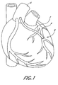
- a saphenous vein graft is depicted in FIGURE 1.
- the graft 2 is used to bypass one of the occluded coronary arteries 4, and connects the aorta 6 to the coronary artery at a location distal the occlusion 8.
- the present invention will be described in connection with a saphenous vein graft, it should be understood that this application is merely exemplary, and the invention can be used in other blood vessels as well.
- a guide catheter having a single lumen is first introduced into the patient's vasculature through an incision made in the femoral artery in the groin and used to guide the insertion of other catheters and devices to the desired site.
- a second catheter is inserted through the guide catheter and past the site of the occlusion.
- the catheter has an occlusive device, such as an inflatable balloon, filter or other mechanical occlusive device, attached at its distal end.
- the occlusive device should be capable of preventing the migration of particles and debris from the working area, either through total or partial occlusion of the vessel. Note that the occlusion of the vessel need not be complete. Substantial occlusion of the vessel can be sufficient for purposes of the present invention.
- the catheter should be sized so as to be slidable with respect to the therapy and aspiration catheters inserted over the catheter.
- the catheter is preferably made of metal such as stainless steel or nitinol, plastics, or composites.
- a guidewire having an occlusive device on its distal end is also suitable for use in the present method.
- the present invention can be effectively used using a number of guidewires or catheters that perform the function of occluding the vessel and allowing for the slidable insertion of various other catheters and devices.
- the term "catheter” as used herein is therefore intended to include both guidewires and catheters with these desired characteristics.
- the catheter apparatus 110 is generally comprised of four communicating members including an elongated tubular member 114, an inflatable balloon member 116, a core-wire member 120 and a coil member 122.
- the catheter apparatus 110 is preferably provided with an outer coating of a lubricous material, such as Teflon.
- the body member 114 of the catheter apparatus 110 is in the form of hypotubing and is provided with proximal and distal ends 114A and 114B as well as an inner lumen 115 extending along the tubular member 114.
- the balloon member 116 is coaxially mounted near the distal end 114B of the tubular member 114 by suitable adhesives 119 at a proximal end 116A and a distal end 116B of the balloon member 116 as shown in FIGURE 11.
- Proximal and distal tapered portions 123A and 123B on either side of the balloon 116 preferably include adhesives.
- Proximal and distal adhesive stops 125 and 126 contact the adhesives 119 to define the working length of the balloon 116.
- a radiopaque marker 127 is preferably located within the proximal tapered portion 123A.
- a notch 128 in the tubular member 114 permits fluid communication between the lumen 115 and the balloon 116.
- a core-wire member 120 of the catheter 110 may be comprised of a flexible wire.
- the flexible wire 120 is preferably secured to the tubular member 114 within the lumen 115 by a combination of adhesives and crimps 129 (FIGURE 11).
- the proximal end 120A of the flexible wire 120 can have a transverse cross sectional area substantially less than the smallest transverse cross-sectional area of the inner lumen 115 of the tubular member 114.
- the flexible wire 120 can also taper towards the distal end 120B to smaller diameters to provide greater flexibility to the flexible wire 120.
- the flexible wire 120 may be in the form of a solid rod, ribbon or a helical coil or wire or combinations thereof.
- the distal end 1208 of the flexible wire 120 is secured to a rounded plug 118 of solder or braze at the distal end 122B of the coil member 122.
- the coil member 122 of the catheter 110 may be comprised of a helical coil.
- the coil member 122 is coaxially disposed about the flexible wire 120, and is secured to the flexible wire 120 by soldering or brazing.
- the balloon member 116 is preferably a compliant balloon formed of a suitable elastic material such as a latex or the like.
- the flexible coil 122 is preferably formed of a wire of platinum or gold based alloys.
- the flexible core-wire 120 and the tubular member 114 are preferably formed of a superelastic nickel-titanium alloy.
- the occlusive device at the distal end of the catheter is actuated to occlude the vessel distal to the existing occlusion to create a working area.
- a therapy catheter then is delivered to the site of the occlusion.
- the term "therapy catheter” is meant to include any of a number of known devices used to treat an occluded vessel.
- a catheter carrying an inflatable balloon for use in balloon angioplasty can be delivered to dilate the occlusion.
- Thermal balloon angioplasty includes the use of heat to "mold" the vessel to the size and shape of the angioplasty balloon. Similarly.
- an intravascular stent can be delivered via a balloon catheter and deployed at the site of the occlusion to keep the vessel open.
- Cutting, shaving, scraping or pulverizing devices can be delivered to excise the occlusion in a procedure known as atherectomy.
- a laser or ultrasound device can also be delivered and used to ablate plaque in the vessel.
- Various thrombolytic or other types of drugs can be delivered locally in high concentrations to the site of the occlusion. It is also possible to deliver various chemical substances or enzymes via a catheter to the site of the stenosis to dissolve the obstruction.
- the term "therapy catheter" encompasses these and similar devices.
- the working area is aspirated to remove fluid and debris.
- Aspiration pressure can be provided through the guide catheter if desired.
- a source of negative pressure is attached at the proximal end of the guide catheter to create reverse flow, and fluid and debris are aspirated through the guide catheter's main lumen.
- an aspiration catheter or similar debris removing device is delivered to the working area to remove particles and any other debris.
- the term "aspiration catheter” includes any device which creates an area of fluid turbulence and uses negative pressure and reverse flow to aspirate fluid and debris, and includes those devices which create a venturi effect within the vessel. It should be noted that any particles which break free during therapy and aspiration procedures will be kept at the site of the procedure within the working area by the occlusive device occluding the distal portion of the vessel in combination with the blood pressure coming from the proximal portion of the vessel. The debris is prevented from migrating elsewhere, and remains localized for removal by aspiration.
- the catheter 10 includes an adaptor 14, preferably a female luer adaptor, and a seal 16 at its proximal end.
- the catheter 10 further includes an aspiration port 18 to which a source of negative pressure is attached.
- the aspiration catheter further comprises a long tubular body 20 having a distal end 22.
- the distal tip 22 can include a radiopaque marker to aid in locating the tip 22 during insertion into the patient, and is preferably soft to prevent damage to the patient's vasculature.
- the aspiration catheter is preferably about 145 cm in length, although this length can be varied as desired.
- the aspiration catheter illustrated in FIGURE 2 Is an over-the-wire catheter.
- the catheter body 20 is hollow, with an internal diameter ranging from about .030" 1.0762 cm) to about .070" (.1778 cm).
- the inner diameter is about .045" (.1143 cm).
- the proximal end of a guidewire 26 is inserted into the distal end of the aspiration catheter 22. and the aspiration catheter 10 is slidably advanced over the guidewire 26, which is positioned Inside the hollow lumen 24 of the aspiration catheter 10.
- the position of the guidewire 26 relative to the body 20 of the aspiration catheter 10 is illustrated in FIGURE 4, but of course can vary.
- a very long guidewire 26, generally around 300 cm in length is used to facilitate the insertion of the aspiration catheter 10 over the guidewire 26.
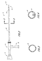
- the aspiration catheter 30 of the present invention is of a single operator design, as illustrated in FIGURES 5-7.
- the catheter 30 has an adaptor 32 and an aspiration port 34 at its proximal end.
- the single operator aspiration catheter 30 further comprises a long tubular body 36 having a distal end 38.
- the distal tip 38 can include a radiopaque marker to aid in locating the tip 38 during insertion into the patient, and is preferably soft to prevent damage to the patient's vasculature.
- a guidewire lumen 40 is attached at the distal end of the shaft 38. This lumen 40 provides a separate lumen, apart from the main aspiration lumen 42 of the catheter 30, for the insertion of the guidewire 26.
- the inner diameter of the guidewire lumen ranges from about .016" (.04064 cm) to about .020" (.0508 cm) for use with a .014" (.03556 cm) guidewire system. In a preferred embodiment, the inner diameter of the lumen is about .019" (.04826 cm).
- This guidewire lumen can be less than 10 cm in length, but can extend 30 cm or longer in a proximal direction. As illustrated in FIGURE 7, during delivery of the aspiration catheter 30, the proximal end of the guidewire 26 is inserted into the distal end of the guidewire lumen 40, and the guidewire lumen 40 is slidably advanced over the guidewire 26.
- the aspiration lumen 42 is advantageously left completely unobstructed to provide more efficient aspiration.
- the guidewire lumen 40 can also include a slit 41 along the entire length in the outside wall of the lumen as shown in FIGURE 7B to facilitate faster and easier insertion and removal of the guidewire 26 through the side wall of the lumen.
- the elongate catheter shaft must have sufficient structural integrity, or "stiffness,” to permit the catheter to be pushed through the vasculature to distal arterial locations without buckling or undesirable bending of the body. It Is also desirable, however, for the body to be fairly flexible near its distal end, so that the tubular body may be navigated through tortuous blood vessel networks.
- the tubular body of the aspiration catheter is formed from a polymer such as polyethylene or PEBAX (Atochem, France) made to have variable stiffness along its length, with the proximal portion of the tubular body being less flexible than the distal portion of the body.
- a tubular body of this construction enables a user to more easily insert the tubular body into vascular networks difficult to access using conventional catheters of uniform stiffness. This is because the stiffer proximal portion provides the requisite structural integrity needed to advance the catheter without buckling, while the more flexible distal region is more easily advanced into and through tortuous blood vessel passageways.
- variable stiffness along the length of the catheter shaft is achieved by forming a polymeric tubular body which incorporates a reinforcement along its length.
- the tubular body may be provided with a reinforcing braid or coil incorporated into its wall structure.
- the reinforcement can be formed of metal or of various polymers.
- the distal region of the catheter is provided with a braid or coil having a higher braid or coil density than that present In the braid or coil of the proximal region. The lower braid density in the proximal region makes it less flexible, or "stiffer", than the distal region of the catheter.
- the precise density of the braiding or coiling provided to the proximal, distal and transition regions can be varied considerably at the time of manufacture, such that catheters having a variety of different flexibility profiles may be created.
- the braid or coil density may be varied within the catheter regions as well, by providing a braid or coil which has a braid or coil density gradient along its length.
- the most proximal part of the proximal region may be provided with a metallic braid having a braid density of about 50-90 picks per inch (about 20-35 picks per cm), with the braid density increasing at a rate of about 2-5 picks per inch (about 1-2 picks per cm) as the braid extends in the distal direction.
- This reinforced construction of the catheter provides adequate proximal stiffness for axial push, while preventing collapse of the distal tip during aspiration.
- the braid is formed of stainless steel, and has a braid density which varies from 50-70 picks per inch (about 20-27 picks per cm) at the most proximal part of the proximal region of the catheter, to 80-100 picks per inch (about 31 to 39 picks per cm) at the most distal part of the distal region of the catheter.
- Reinforcing braids or coils may be introduced into the structure of the catheter body through conventional catheter forming techniques.
- the tubular body may be formed by inserting a 72D PEBAX tube into a variable braid density stainless steel sleeve, and then inserting the sleeved tube into a 72D PEBAX outer tube of the same length, so that the braided sleeve is sandwiched between the two tubes.
- a shaping mandrel may be inserted within the inner PEBAX tube, and shaping container over the outer PEBAX tube, and the entire apparatus may then be placed in a hot box kept at a temperature slightly greater than the melting temperature of the PEBAX tubes.
- the PEBAX tubes will melt and fuse together, and once cooled, will form a tubular body incorporating the braid. This same technique can be used to form a tubular body incorporating a coil.
- variable stiffness of the tubular body may be achieved by forming the proximal and distal regions of the tubular body out of polymeric materials having differing degrees of stiffness. For example, one half of an inner tube of 72D PEBAX may be inserted into an outer tube of 400 PEBAX, and the other half of the inner tube may be inserted into a 72D PEBAX outer tube. The combination may then be heat fused, as described above. The 40D/72D PEBAX combination forms a more flexible tubular body than the region of the 72D/72D PEBAX combination. More or less flexible materials may be used as desired to alter the flexibility of the resulting tubular body. Furthermore, the flexibility of the various regions of a tubular body formed in this manner may be varied further by incorporating a braid or coil having either a uniform braid density or coil pitch, or a varying density or coil, into the tubular body, as described above.
- the body may be formed out of polymers such as polyethylene, PEBAX, polyimide, polyether etherketone, and the like. Different materials might also be combined to select for desirable flexibility properties.
- catheter body has been described in the context of having two regions of differing flexibility, it will be readily appreciated by those of skill in the art that three or more regions of differing flexibility may easily be provided, by adapting the teachings contained herein.
- a further embodiment of the aspiration catheter includes at least one support mandrel incorporated in to the catheter body to further strengthen the catheter.
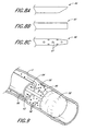
- One such catheter having two support mandrels is illustrated in FIGURE 13.
- This over-the-wire aspiration catheter 110 is approximately 135-140 cm. in length, and includes two lumens, an aspiration lumen 112 and a separate guidewire lumen 114. Both lumens 112, 114 extend from the proximal end of the catheter 118 to the distal end 120.
- the catheter 110 preferably includes an adaptor 111 at its proximal end 118.
- the adaptor 111 connects to a source of negative pressure to provide aspiration through the aspiration lumen 112.
- the catheter 110 is slidably advanced over a guidewire positioned within the guidewire lumen 114, as described above.
- the aspiration and guidewire lumens 112, 114 of the present invention are adjacent one another.
- Two support mandrels 116a, 116b are positioned alongside the lumens 112, 114 to provide added stiffness to the length of the catheter body 110.
- the mandrels 116a, 116b are preferably formed of stainless steel, but could be made of any material which would provide additional strength to the catheter body.
- the outer diameter of the mandrel is preferably no more the 0.010" (0.0254 cm), to maintain the low profile of the catheter body 110.
- the mandrals 116a, 116b extend from the proximal end of the catheter body 118, ending approximately 35 cm from the distal end of the catheter 120.
- the mandrels 116a, 116b are positioned adjacent the dual lumen tubing 112, 114 of the catheter body 110.
- a shrink tube 122 formed of polyethylene terephthalate (PET) or other suitable material surrounds the dual-lumen tubing 112, 114 and the mandrels 116a, 116b.
- PET polyethylene terephthalate
- the shrink tube 122 tightens around the dual lumen tubing 112, 114 and the mandrels 116a, 116b, maintaining the position of the mandrels 116a, 116b adjacent the lumens 112, 114 for the length of the catheter body 110.
- the shrink tube 122 extends approximately 10 cm past the end of the mandrels 116a, 116b at the proximal end of the catheter 118, to secure the shrink tube 122 around the catheter body 110 and prevent the mandrels 116a, 116b from moving.
- the shrink tube 122 therefore extends from the proximal end of the catheter 118 to a position approximately 25 cm from the distal tip 120 of the aspiration catheter 110.
- the distal tip of the aspiration catheter is preferably formed from 25D to 40D PEBAX with a radiopaque filler such as BaS04.
- the distal end of the catheter can also be provided with a soft distal tip which is not pre-formed with the tubular body, but is instead attached to the body as a post manufacturing step.
- the distal tip is preferably soft enough and flexible enough so as to minimize trauma to body vessels as the catheter is advanced and to facilitate navigation of the catheter in tortuous vessels, but must also be strong enough to avoid collapse during aspiration.
- the distal tip is formed as a 0.5 cm sleeve of 25-350 PEBAX and is bonded to the tubular body by use of an adhesive.
- the distal tip may be attached to the tubular body by heat bonding, as is known to those of skill in the art.
- the entire distal end of the aspiration catheter can also be attached as a separate post manufacturing step.
- a tubing made of polyethylene (PE), PEBAX, or polyimide can be fused to the distal end of the main body section of the catheter. This tubing can be from about 5 to about 60 em in length, but is preferably around 30 cm.
- the distal end of the aspiration catheter can also be provided with a radiopaque material.
- radiopaque material serves as a marker 124 to help the user position the catheter inside the patient's body as shown in Figure 13.
- Various well-known radiopaque materials may be used in the distal end to form the marker, such as platinum or gold.
- BaS04 can be incorporated into the polymer resin itself.
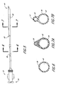
- FIGURES 8A, 8B, and 8C illustrate various embodiments of the distal end of the aspiration catheter of the present invention.
- FIGURE 8A shows the preferred tip 44, wherein the end has been angled and is oblique to provide effective retrieval of particles. The angle can be from about 5 degrees to about 90 degrees; an angle of about 25 degrees is preferred. This angled tip 44 is also shown in FIGURE 5. This angled tip 44 maximizes the area of aspiration.
- the distal tip of the aspiration catheter can also be blunt 45, as shown in FIGURE 8B, or can be tapered 46. Side ports 47 can be drilled along the distal tip of the catheter to enhance the aspiration rate, as illustrated in FIGURES 8C and 2.
- the aspiration catheter can be configured such that the therapy catheter can be inserted through the lumen of the aspiration catheter.
- the lumen is made large enough to accommodate the desired therapy catheter. This allows the aspiration catheter and the therapy catheter to be delivered into the patient at the same time. When therapy is complete, the therapy catheter is removed while the aspiration catheter remains in place. This eliminates the need to separately deliver the aspiration catheter after removal of the therapy catheter, saving valuable time.
- the shaft of the therapy catheter is sufficiently small to allow aspiration around the catheter, the therapy catheter can remain in place during aspiration. This too saves valuable time by eliminating the need to remove the therapy catheter prior to aspirating.
- the size of the guide catheter used during this type of procedure be sized from at least 8 to about 10 French to accommodate the size of the "over ⁇ the ⁇ therapy ⁇ catheter" aspiration catheter.
- the therapy catheter can be built over the aspiration catheter.
- a dual or triple lumen catheter having a dilatation balloon at its distal end can be used.
- One lumen is used to inflate the dilatation balloon to be used for angioplasty, while the second lumen is used for aspiration.
- the third lumen is used as a guidewire lumen.
- the aspiration catheter can be designed to deploy a stent within the occluded artery, or could include an atherectomy device on its distal end. These designs allow a single combined aspiration catheter and therapy catheter to be delivered into the patient. When therapy is complete, aspiration is carried out without the need to first remove the therapy catheter or separately deliver an aspiration catheter.
- the distal end of the aspiration catheter 260 may incorporate an occlusive device 262, such as an inflatable balloon.
- the balloon 262 is mounted on the distal end of the catheter 260, end an inflation lumen extends the length of the catheter body, from the balloon 262 to the proximal end of the catheter Inot shown).
- the aspiration catheter may be used not only for aspiration, but also to occlude the vessel, where desired.
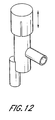
- the proximal end of the aspiration catheter can be fitted with a valve 165, as illustrated in FIGURE 12.
- the valve 165 allows the user to regulate the aspiration pressure.
- a syringe can be connected to the valve 165 and aspiration port at the proximal end of the catheter. With the valve 165 closed, the syringe piston can be retracted completely to provide a vacuum. The valve 165 is then opened to provide aspiration at the distal end of the aspiration catheter. Aspiration pressure can be provided in short bursts (pulsed) or continuously as the user desires by opening and closing the valve 165 at the proximal end of the catheter. This valve 165 therefore provides control over the aspiration within the vessel.
- a preferred valve is available from Burron OEM, a division of B. Braun Medical Inc., under the name TRAC VALVE.
- the aspiration catheters of the present invention can also include a coating on the outer surface.
- Suitable coatings include hydrophilic, hydrophobic, and antithrombogenic coatings, or a combination thereof.
- suitable coatings include heparin, silicone, polyurethane and PVP.
- the proximal end of the aspiration catheter may also include a marker which indicates to the physician the approximate catheter length which can safely and rapidly be inserted into the patient.
- This femoral marker is illustrated as part of the aspiration catheter 130 in FIGURE 15.
- This marker 132 is placed on the aspiration catheter 130 approximately 95 cm from the distal tip 134 of the catheter. This length is approximately equal to the distance from the incision site in the femoral artery to the ostium of the coronary artery in the average human being.
- the physician rapidly advances the catheter 130 into the patient's vasculature, until the femoral marker 132 near the proximal end of the catheter 136 is just outside the patient's body.
- the marker 132 is an indication to the physician to slow the insertion of the catheter 130, and to turn on the fluoroscopy to carefully deliver the distal tip of the catheter 134 to the desired position. This therefore reduces the patient's exposure to x-rays during the procedure.
- the femoral marker 132 may be made of any biocompatible material, including plastics and metals, however, any visible marker 132 on the outer surface of the catheter 130 may be used.
- FIGURE 15 illustrates another embodiment of aspiration catheter 130, which incorporates both the femoral marker 132 described above, and a support sheath 140.
- the support sheath 140 is located on the proximal end of the catheter 136.
- the proximal end of the aspiration catheter 136 may include adaptors 142 and valves.
- commonly used adaptors and valves include a Touhy-Borst or hemostasis valve (not shown), which are positioned at the proximal end of the aspiration catheter 136.
- the hemostasis valve surrounds the outer surface of the aspiration catheter 130, and tightens down around the aspiration catheter 130 to prevent the patient's blood from flowing out around the aspiration catheter 130. As the valve is tightened, there is some risk that the aspiration catheter 130 may be crushed. Accordingly, a support sheath 140 may be added to the proximal end of the catheter 136 to prevent collapse or crushing of the catheter 136.
- the support sheath 140 allows the aspiration catheter 130 to move within the hemostasis valve.
- the physician may wish to move the distal tip of the aspiration catheter 130 in a proximal direction during aspiration, to ensure complete aspiration of debris. If the hemostasis valve is tightened directly onto the aspiration catheter 130, the catheter 130 is not free to slide back and forth. If the valve is tightened on the support sheath 140, however, there is a sufficient gap between the support sheath 140 and the body of the aspiration catheter 130 to allow for slidable movement of the aspiration catheter 130.
- the support sheath 140 is preferably about 3-9 cm in length, and more preferably is about 6 cm in length. It is positioned near the proximal end of the catheter 136, just distal to the proximal adaptor 142.
- the support sheath 140 is preferably formed of polyimide.
- the sheath 140 surrounds the outer surface of the aspiration catheter 130, as shown in FIGURE 16, giving that portion of the aspiration catheter 130 greater strength and preventing the valve from crushing the aspiration lumen 144.
- the aspiration catheter of the present invention may be used as part of an aspiration system, as illustrated in FIGURE 17.
- FIGURE 17 illustrates a single operator type aspiration catheter 150.
- the aspiration catheter 150 is connected at its proximal end 152 to an extension line 154, through use of an adaptor 153.
- Aspiration pressure is provided through the extension line 154 to the aspiration catheter 150.
- the extension line 154 in turn is fitted with a valve, or stopcock 158, at its proximal end 156.
- This stopcock 158 controls the delivery of the aspiration pressure through the extension line 154.
- no aspiration pressure is delivered to the aspiration catheter 160.
- any suitable valve may be used to control the delivery of aspiration pressure to the aspiration catheter.
- use of a valve 158 provides the user with increased control over delivery of the aspiration pressure.
- a preferred extension line and stopcock assembly is available from Mallinkrodt Medical Inc., Irvine, CA, catalog no. 140083.
- a source of aspiration pressure such as the syringe 160 illustrated in FIGURE 17, is connected to the stopcock 158. If desired, the extension line 154 may be eliminated, and the source of aspiration pressure and the valve 158 may be connected directly to the aspiration catheter 150.
- the components of the aspiration system 150, 154, 158 and 160 are assembled as described above.
- the stopcock 158 or valve is closed, and negative pressure is applied.
- the plunger on the syringe 160 is retracted to provide negative pressure.
- the stopcock 158 is opened, which supplies negative pressure through the extension line 154 and down to the distal end of the aspiration catheter 150.
- the stopcock 158 is closed.
- the stopcock 158 may be opened and closed repeatedly to deliver the aspiration pressure in a pulsed manner if desired.
- a guide catheter (not shown) is introduced into the patient's vasculature through an incision in the femoral artery in the groin of the patient.
- the guide catheter has a single large lumen, and is used to guide the insertion of other catheters and devices.
- the guide catheter is advanced until it reaches the aorta and the ostium of the vein graft, where it will remain in place throughout the procedure.
- Fluoroscopy is typically used to guide the guide catheter and other devices to the desired location within the patient.
- the devices are frequently marked with radiopaque markers to facilitate visualization of the insertion and positioning of the devices within the patient's vasculature.
- a catheter or guidewire 50 having an occlusive device at its distal end is delivered through the guide catheter into the saphenous vein graft 5 and past the site of the occlusion 56.
- the occlusive device is an inflatable balloon 52.
- the balloon 52 is inflated to occlude the vein graft 5 at a site distal to the occlusion 56.
- the blood coming from the aorta enters the saphenous vein graft 5 and keeps any particles 58 dislodged during the procedure from flowing proximally.
- the blood pressure and flow coming from the aorta provides the irrigation necessary for aspiration.
- the blood pressure in the vessel is preferably at least about 0.2 psi (1.38 kPa), and the proximal flow rate is at least about 10 cc per minute.
- a therapy catheter (not shown) is then delivered, if desired.
- the therapy catheter can be any of a number of devices, including a balloon catheter used to perform angioplasty, a catheter which delivers a stent, a catheter for delivering enzymes, chemicals, or drugs to dissolve and treat the occlusion, an atherectomy device, a rheolitic device, or a laser or ultrasound device used to ablate the occlusion.
- the therapy catheter can be eliminated and use of the guide catheter or a separate aspiration catheter alone can be used to aspirate the occlusion. This method is especially useful to remove amboli from the coronary arteries following acute myocardial infarction, because the aspiration catheter can be made small enough to enter the coronary arteries.
- the therapy catheter is withdrawn from the patient's body and an aspiration catheter 60 is delivered over the guidewire 50 and through the guiding catheter.
- an aspiration catheter 60 is delivered over the guidewire 50 and through the guiding catheter.
- a single operator type aspiration catheter can be used, in which only a portion of the aspiration catheter rides over the guidewire, which is inserted into a separate guidewire lumen.
- the distal tip of the aspiration catheter 64 is initially positioned close to the occlusive balloon 52 and aspiration is begun. The operator then slides the aspiration catheter in a proximal direction, increasing the distance between the distal tip 64 and the balloon 52. Aspiration can therefore occur anywhere between about 0 to 20 cm proximal to the occlusive device. If desired, the distal tip of the aspiration catheter 64 can be slidably advanced in the distal direction more than once to ensure complete aspiration of all debris. As explained above, aspiration pressure can be pulsed if desired.
- the present catheter system and method which uses a separate aspiration catheter that can be moved back and forth and positioned anywhere within the blood vessels, allows the physician the flexibility to aspirate under a wide variety of conditions and to provide aspiration in a wide variety of locations within the body.
- the blood pressure supplied by the aorta will move any particles 58 from a position proximal to the distal tip of the aspiration catheter 64, thus allowing them to be aspirated. If a particle, however, is too far distal to the tip of the aspiration catheter 64, the blood pressure will keep it there and not allow it to aspirate from the vessel 5. Once aspiration has begun, additional blood will flow into the area, creating turbulence and allowing for successful removal of debris.
- a preferred source of negative pressure is any container containing a fixed vacuum, such as a syringe, attached to the proximal end of the aspiration catheter at the aspiration port 34 (see FIGURES 5 and 17).
- a mechanical pump or bulb or any other appropriate source of negative pressure can also be used.
- Other aspiration methods including those which utilize a venturi effect, can also be used.
- the difference between the existing pressure within the vessel and the aspiration pressure within the vessel should not exceed 60 psi (41.4 MPa), and more preferably, should not exceed about 30 psi (20.7 MPa). If too much aspiration pressure is applied, the change in pressure in the vessel will be too great and damage may occur to the vessel itself.
- the aspiration catheter 60 is removed.
- the balloon 52 is deflated and the guidewire 50 and guiding catheter are removed.
- the aspiration catheter can be sized such that it can receive the therapy catheter within its lumen, or the therapy catheter can be built over the aspiration catheter.
- an angioplasty balloon can be attached to the distal end of the aspiration catheter.
- the aspiration catheter can be designed to deploy a stent within the occluded artery, or could include an atherectomy device on its distal end.
- the aspiration catheter and the therapy catheter are delivered over the guidewire and into the vein graft together. When therapy is complete, the therapy catheter is removed while the aspiration catheter remains in place. Alternatively, the therapy catheter remains in place during aspiration, eliminating the need to remove the therapy catheter prior to aspiration, which saves precious time.
- the aspiration catheter, therapy catheter, guidewire and guiding catheter are removed from the patient's body. Delivering the aspiration catheter and therapy catheter together saves time, which is critical during these types of procedures.
- the guide catheter can be used to provide aspiration through its main lumen.
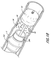
- FIGURE 18 An alternative method of use of the present invention will now be described in connection with FIGURE 18. Again, although use of the method in a saphenous vein graft is described, it should be noted that this application is merely exetnplary, and that the present invention can be used in other blood vessels and to remove other types of occlusions as well.
- a guide catheter (not shown) is first introduced into the patient's vasculature through an incision in the femoral artery in the groin of the patient.
- the guide catheter has a single large lumen, and is used to guide the insertion of other catheters and devices.
- the guide catheter is advanced until it reaches the aorta and the ostium of the vein graft, where it will remain in place throughout the procedure.
- Fluoroscopy is typically used to guide the guide catheter and other devices to the desired location within the patient.
- the devices are frequently marked with radiopaque markers to facilitate visualization of the insertion and positioning of the devices within the patient's vasculature.
- a guidewire 50 having an occlusive device on its distal end 52 and a catheter having an occlusive device on its distal end, such as the aspiration catheter 260 illustrated in FIGURE 18, are delivered to a position just proximal to the occlusion 56.
- the guidewire 50 and catheter 260 can be delivered together to save time, or can be delivered separately. If delivered together, the guidewire 50 is inserted into the main lumen or guidewire lumen of the catheter 260, and the two are delivered simultaneously. Once the guidewire 50 and catheter 260 are in position proximal to the occlusion 56, the occlusion balloon 262 on the end of the catheter 260 is inflated, occluding the vessel 5.
- the guidewire 50 is then advanced across the occlusion 56, until the occlusion balloon 52 is distal to the occlusion 56.
- the occlusion balloon 52 on the guidewire 50 is then inflated. This method is particularly useful in saphenous vein grafts 5 where the occlusion 56 tends to be friable, and there is a greater risk of dislodging particles 58 which could then travel downstream.
- the occlusion balloon 262 proximal to the occlusion is then deflated.
- the aspiration catheter 260 is then used to aspirate any loose particles 58 from the area proximal to the occlusion balloon 52 positioned distal to the occlusion 56.
- an aspiration catheter is not used to occlude the vessel, the catheter bearing the proximal occlusive device is removed following deactivation of the occlusive device, and a separate aspiration catheter is delivered and used to aspirate the area proximal to the distal occlusion balloon 52.
- the aspiration catheter 260 is then removed.
- the occlusion balloon 52 on the guidewire 50 remains inflated, occluding the vessel 5 at a site distal to the occlusion 56.
- therapy is then performed on the occlusion, the area is aspirated, the distal occlusion balloon 52 is deflated, and the guidewire 50 and guiding catheter are removed.
Landscapes
- Health & Medical Sciences (AREA)
- Life Sciences & Earth Sciences (AREA)
- Heart & Thoracic Surgery (AREA)
- Animal Behavior & Ethology (AREA)
- Engineering & Computer Science (AREA)
- Biomedical Technology (AREA)
- General Health & Medical Sciences (AREA)
- Public Health (AREA)
- Veterinary Medicine (AREA)
- Anesthesiology (AREA)
- Pulmonology (AREA)
- Hematology (AREA)
- Biophysics (AREA)
- Surgery (AREA)
- Vascular Medicine (AREA)
- Child & Adolescent Psychology (AREA)
- Nuclear Medicine, Radiotherapy & Molecular Imaging (AREA)
- Medical Informatics (AREA)
- Molecular Biology (AREA)
- Physics & Mathematics (AREA)
- Electromagnetism (AREA)
- Optics & Photonics (AREA)
- Otolaryngology (AREA)
- Orthopedic Medicine & Surgery (AREA)
- Media Introduction/Drainage Providing Device (AREA)
- Saccharide Compounds (AREA)
- Medicines Containing Plant Substances (AREA)
- External Artificial Organs (AREA)
- Polysaccharides And Polysaccharide Derivatives (AREA)
Abstract
Description
- The present invention relates to aspiration catheters for aspirating emboli, thrombi, and other types of particles from the vasculature of a patient, the apparatus being particularly well suited for aspiration within saphenous vein grafts, coronary arteries, and similar vessels.
- Human blood vessels often become occluded or completely blocked by plaque, thrombi, other deposits, emboli or other substances, which reduce the blood carrying capacity of the vessel. Should the blockage occur at a critical place in the circulatory system, serious and permanent injury, or even death, can occur. To prevent this, some form of medical intervention is usually performed when significant occlusion is detected.
- Coronary heart disease is an extremely common disorder in developed countries, and is the leading cause of death in the U.S. Damage to or malfunction of the heart is caused by narrowing or blockage of the coronary arteries (atherosclerosis) that supply blood to the heart. The coronary arteries are first narrowed and may eventually be completely blocked by plaque, and may further be complicated by the formation of thrombi (blood clots) on the roughened surfaces of the plaques. Myocardial infarction can result from atherosclerosis, especially from an occlusive or near occlusive thrombi overlying or adjacent to the atherosclerotic plaque, leading to death of portions of the heart muscle. Thrombi and emboli also often result from myocardial infarction, and these clots can block the coronary arteries, or can migrate further downstream, causing additional complications.
- Various types of intervention techniques have been developed which facilitate the reduction or removal of the blockage in the blood vessel, allowing increased blood flow through the vessel. One technique for treating stenosis or occlusion of a blood vessel is balloon angioplasty. A balloon catheter is inserted into the narrowed or blocked area, and the balloon is inflated to expand the constricted area. In many cases, near normal blood flow is restored. It can be difficult, however, to treat plaque deposits and thrombi in the coronary arteries, because the coronary arteries are small, which makes accessing them with commonly used catheters difficult.
- Other types of intervention include atherectomy, deployment of stents, introduction of specific medication by infusion, and bypass surgery. Each of these methods are not without the risk of embolism caused by the dislodgement of the blocking material which then moves downstream. In addition, the size of the blocked vessel may limit percutaneous access to the vessel.
- In coronary bypass surgery, a more costly and invasive form of intervention, a section of a vein, usually the saphenous vein taken from the leg, is used to form a connection between the aorta and the coronary artery distal to the obstruction. Over time, however, the saphenous vein graft may itself become diseased, stenosed, or occluded, similar to the bypassed vessel. Atherosclerotic plaque in saphenous vein grafts tends to be more friable and less fibrocalcific than its counterpart in native coronary arteries.
- Diffusely diseased old saphenous vein grafts with friable atherosclerotic lesions and thrombi have therefore been associated with iatrogenic distal embolic debris. Balloon dilatation of saphenous vein grafts is more likely to produce symptomatic embolization than dilatation of the coronary arteries, not only because of the difference in the plaque but also because vein grafts and their atheromatous plaques are generally larger than the coronary arteries to which they are anastamosed. Once the plaque and thrombi are dislodged from the vein they can move downstream, completely blocking another portion of the coronary artery and causing myocardial infarction. In fact, coronary embolization as a complication of balloon angioplasty of saphenous vein grafts is higher than that in balloon angioplasty of native coronary arteries. Therefore, balloon angioplasty of vein grafts is performed with the realization that involvement by friable atherosclerosis is likely and that atheroembolization represents a significant risk.
- Because of these complications and high recurrence rates, old diffusely diseased saphenous vein grafts have been considered contraindications for angioplasty and atherectomy, severely limiting the options for minimally invasive treatment. However, some diffusely diseased or occluded saphenous vein grafts may be associated with acute ischemic syndromes, necessitating some form of intervention.
- There is therefore a need for improved methods of treatment for occluded vessels such as saphenous vein grafts and the smaller coronary arteries which decrease the risks to the patient.
- An aspiration catheter according to the preamble of claim 1 is disclosed in EP-A-0 693 295.
- The present invention provides an aspiration catheter, comprising:
- an elongate tubular body having a proximal end and a distal end and an aspiration lumen extending between the proximal and distal ends; an aspiration port at the proximal end of the tubular body, the aspiration port being in fluid communication with the aspiration lumen; an aspiration opening at the distal end of the tubular body, the aspiration opening being in fluid communication with the aspiration lumen; and a source of negative pressure capable of establishing fluid communication with the aspiration lumen; characterised by a guidewire lumen separate from and adjacent the aspiration lumen; and extending less than 40 cm in a proximal direction from the distal end of the elongate tubular body; and wherein the cross section of the distal and proximal ends of the aspiration lumen is circular. The present invention advantageously satisfies the need in the prior art by providing a catheter adapted to be compactly utilized in even the smaller size blood vessels. It can also be easily adapted to provide efficient and speedy evacuation in larger size vessels. This system is compatible with more common therapy devices in widespread use today, and is designed for rapid evacuation and ease of use.
- The catheters of the present invention are provided in single operator form. The catheters are sized so as to be used in very small blood vessels. Radiopaque markers are preferably incorporated into the distal ends of the catheters to facilitate their positioning within the body; similarly, a marker may be placed on the proximal end of the catheter to aid ia the insertion of the catheter in to the patient. The catheters may be provided with varying flexibility along the length of the shaft, such that they are soft and flexible enough to be navigated through the vasculature of a patient without causing damage, but are stiff enough to sustain the axial push required to position the catheter properly and to sustain the aspiration pressures. A support mandrel may be Incorporated into the catheter to provide additional strength. A support sheath is preferably included to prevent crushing of the aspiration lumen when the catheter is used in conjunction with valves, adaptors or other fittings.
- The catheters are preferably sized so as to allow the slidable insertion of a therapy catheter through the main aspiration lumen of the aspiration catheter. Alternatively, the therapy catheter can be built over the aspiration catheter. In either case, the aspiration and therapy catheters can be delivered simultaneously, saving valuable time during the procedure.
- One embodiment of the aspiration catheter of the present invention therefore comprises an elongate flexible tubular body having a proximal end and a distal end. The catheter body or shaft incorporates a reinforcement such as a metallic braid or coli or a polymer coil to provide strength and flexibility to the device. A main lumen extends the length of the tubular body, and an aspiration port at the proximal end of the catheter body is in fluid communication with the main lumen, such that aspiration pressure can be provided through the port and main lumen. The distal tip on the catheter is formed of a more flexible material than that used to form the rest of the catheter shaft. Markers are preferably incorporated in to both the distal and proximal ends of the catheter to assist in positioning the catheter in the patient.
- The reinforcement can be formed from a variety of materials, including polymers, stainless steel, silver or gold plated stainless steel, ELGILOY, platinum, nitinol, or a combination thereof. The distal end of the catheter body is preferably more flexible than the proximal end, and this can be achieved by providing a braid or coil density at the distal end which is greater than the braid or coil density at the proximal end. At least one support mandrel may be used to provide the catheter with additional strength.
- The catheter's main lumen is preferably sized to receive at least one separate catheter, such as a therapy catheter, which is slidably disposed therein. The inner diameter of the main lumen is preferably about .045" (0.1143 cm).
- The aspiration catheter of the present invention includes a second lumen adjacent the main lumen which is adapted to receive a guidewire therethrough. The second lumen extends less than 40 cm or less than 20 cm in a proximal direction from the distal end of the body. The second lumen can contain a slit through a side wall to allow insertion and removal of the guidewire therethrough. In a preferred embodiment, the second lumen has an inner diameter of approximately .020" (0.0508 cm) to receive a .014" (0.03556 cm) diameter guidewire.
- The distal tip of the catheter can have at least one side port to facilitate aspiration. The distal tip can be tapered, blunt, or angled to create an oblique opening. The catheter preferably also comprises a valve in fluid communication with the main lumen, to control the application of aspiration pressure at the distal end of the device. The aspiration catheter of the present invention can also incorporate various coatings, such as hydrophilic or hydrophobic coatings, antithrombogenic coatings, or a combination thereof.
- In yet another embodiment of the present invention, the aspiration catheter further comprises a therapeutic device attached to the distal end of the tubular body. The therapeutic device can be an inflatable balloon and the catheter can include a separate inflation lumen for the balloon adjacent the main lumen.
- The aspiration catheter may be part of an aspiration system which comprises the aspiration catheter, an extension line having a valve or stopcock to control the delivery of the aspiration pressure, and a source of negative pressure such as a syringe.
- Accordingly, the catheters of the present invention provide for very fast and efficient aspiration of the working area surrounding the occlusion in a blood vessel. The catheters can be utilized in a wide range of vessel diameters, including extremely small ones, are easy to use and can quickly and efficiently evacuate occlusions and debris, allowing the physician to restore normal blood flow in these vessels in a very short period of time.
-
- FIGURE 1 is a perspective view of a human heart showing a saphenous vein graft used to bypass a portion of the coronary arteries.
- FIGURE 2 is a side view of an over-the-wire aspiration catheter which does not fall within the scope of the present invention, but is shown by way of background only.
- FIGURE 3 is a cross section of the aspiration catheter of FIGURE 2, taken along line 3-3 in Figure 2.
- FIGURE 4 is a cross section of the aspiration catheter of FIGURE 2 showing a guide wire over which the aspiration catheter rides.
- FIGURE 5 is a side view of a single operator type aspiration catheter in accordance with the present invention.
- FIGURE 6 is a cross section of the proximal end of the aspiration catheter of FIGURE 5, taken along line 6-6 of FIGURE 5.
- FIGURE 7A is a cross section of one embodiment of the distal end of the aspiration catheter of FIGURE 5, taken along line 7-7 of FIGURE 5.
- FIGURE 7B is a cross section of another embodiment of the distal end of the aspiration catheter of FIGURE 5, also taken along line 7-7 of FIGURE 5, showing a slit in the outer wall of the guidewire lumen through which the guidewire can be Inserted and removed.
- FIGURES 8A-C are side views of the various embodiments of the distal end of the aspiration catheter of the present invention.
- FIGURE 9 is a perspective view of an over-the-wire aspiration catheter such as that of FIGURE 2, and guidewire inserted into a saphenous vein graft, with the vein graft shown partially cut away.
- FIGURE 10 is a schematic view of an occlusion catheter apparatus for use in the method of the present invention;
- FIGURE 11 is a schematic cross-sectional view of a distal portion of the catheter apparatus shown in FIGURE 10.
- FIGURE 12 is a perspective view of a valve which can be positioned at the proximal end of the catheter of the present invention to control aspiration.
- FIGURE 13 is a side view of another over-the-wire aspiration catheter such as that of Figure 2.
- FIGURE 14 is a cross-sectional view of the aspiration catheter of FIGURE 13, taken along line 14-14 in FIGURE 13.
- FIGURE 15 is a side view of another embodiment of a single operator type aspiration catheter according to the invention.
- FIGURE 16 is a cross-sectional view of the aspiration catheter of FIGURE 15, taken along line 16-16 in FIGURE 15.
- FIGURE 17 is a side view of an aspiration system, which includes an aspiration catheter, an extension line having a stopcock, and a source of aspiration pressure.
- FIGURE 18 is a perspective view of an over-the-wire aspiration catheter such as in FIGURE 2, but having an occlusive balloon on its distal end and guidewire inserted into a saphenous vein graft, with the vein graft shown partially cut away.
- The present invention provides novel aspiration catheters for aspirating emboli, plaque, thrombi or other occlusions from a blood vessel. The present invention is adapted for use in the treatment and removal of an occlusion in a blood vessel in which the occlusion has a length and a width or thickness which at least partially occludes the vessel's lumen. Thus, the catheters of the present invention are effective in treating both partial and complete occlusions of the blood vessels. As used herein, "occlusion" includes both partial and complete occlusions, stenoses, emboli, thrombi, plaque and any other substance which at least partially occludes the vessel's lumen,
- The catheter of the present invention can be used to provide aspiration with or without the need for a separate irrigation catheter and irrigation fluid. In the context of removing plaque, thrombi or other blockages from blood vessels, it has heretofore been proposed that an isolated "chamber" surrounding the occlusion be created prior to attempting treatment, and that separate irrigation fluid be provided through an irrigation catheter to the chamber. It has been discovered that isolation of the occlusion is not required in some cases, and that the occlusion can be successfully removed through therapy and/or aspirating of the resulting debris without the need for delivery of a separate irrigation catheter and irrigation fluid in those vessels where certain pressure and fluid flow conditions exist, such as saphenous vein grafts, coronary arteries, carotid arteries and similar vessels.
- In non-bifurcated areas of the blood vessels, it has been discovered that fluid from the proximal portion of the same vessel acts as an infusion source. One can therefore occlude only the distal portion of the vessel to create a working area surrounding the occlusion and allow blood to flow from the proximal portion of the vessel into the working area. The working area surrounding the occlusion is aspirated through the guiding catheter or aspiration catheter. It should be noted that, as used herein, "proximal" refers to the portion of the apparatus closest to the end which remains outside the patient's body, and "distal" refers to the portion closest to the end inserted into the patient's body.
- The apparatus of the present invention can be used in any vessel of the body where the pressure is at least 0.2 psi (1.38 kPa), and preferably, is about 1.2 psi (8.27 kPa), with a flow rate of at least 10 cc per minute. The apparatus is particularly suited for use in removal of occlusions from saphenous vein grafts, coronary and carotid arteries, and in other non-branching vessels having similar pressures and flow where a suitable working area can be created. A saphenous vein graft is depicted in FIGURE 1. The
graft 2 is used to bypass one of the occluded coronary arteries 4, and connects theaorta 6 to the coronary artery at a location distal theocclusion 8. Although the present invention will be described in connection with a saphenous vein graft, it should be understood that this application is merely exemplary, and the invention can be used in other blood vessels as well. - A guide catheter having a single lumen is first introduced into the patient's vasculature through an incision made in the femoral artery in the groin and used to guide the insertion of other catheters and devices to the desired site. Following insertion of the guide catheter, a second catheter is inserted through the guide catheter and past the site of the occlusion. The catheter has an occlusive device, such as an inflatable balloon, filter or other mechanical occlusive device, attached at its distal end. The occlusive device should be capable of preventing the migration of particles and debris from the working area, either through total or partial occlusion of the vessel. Note that the occlusion of the vessel need not be complete. Substantial occlusion of the vessel can be sufficient for purposes of the present invention. The catheter should be sized so as to be slidable with respect to the therapy and aspiration catheters inserted over the catheter. The catheter is preferably made of metal such as stainless steel or nitinol, plastics, or composites. A guidewire having an occlusive device on its distal end is also suitable for use in the present method. The present invention can be effectively used using a number of guidewires or catheters that perform the function of occluding the vessel and allowing for the slidable insertion of various other catheters and devices. The term "catheter" as used herein is therefore intended to include both guidewires and catheters with these desired characteristics.
- A catheter suitable for use in the method described above is illustrated in FIGURES 10 and 11. The catheter apparatus 110 is generally comprised of four communicating members including an
elongated tubular member 114, aninflatable balloon member 116, a core-wire member 120 and acoil member 122. The catheter apparatus 110 is preferably provided with an outer coating of a lubricous material, such as Teflon. - The
body member 114 of the catheter apparatus 110 is in the form of hypotubing and is provided with proximal anddistal ends inner lumen 115 extending along thetubular member 114. Theballoon member 116 is coaxially mounted near thedistal end 114B of thetubular member 114 bysuitable adhesives 119 at aproximal end 116A and adistal end 116B of theballoon member 116 as shown in FIGURE 11. Proximal and distaltapered portions 123A and 123B on either side of theballoon 116 preferably include adhesives. Proximal and distal adhesive stops 125 and 126 contact theadhesives 119 to define the working length of theballoon 116. Aradiopaque marker 127 is preferably located within the proximaltapered portion 123A. Anotch 128 in thetubular member 114 permits fluid communication between thelumen 115 and theballoon 116. - A core-
wire member 120 of the catheter 110 may be comprised of a flexible wire. Theflexible wire 120 is preferably secured to thetubular member 114 within thelumen 115 by a combination of adhesives and crimps 129 (FIGURE 11). Theproximal end 120A of theflexible wire 120 can have a transverse cross sectional area substantially less than the smallest transverse cross-sectional area of theinner lumen 115 of thetubular member 114. Theflexible wire 120 can also taper towards thedistal end 120B to smaller diameters to provide greater flexibility to theflexible wire 120. However, theflexible wire 120 may be in the form of a solid rod, ribbon or a helical coil or wire or combinations thereof. As shown in FIGURE 11, the distal end 1208 of theflexible wire 120 is secured to arounded plug 118 of solder or braze at thedistal end 122B of thecoil member 122. Thecoil member 122 of the catheter 110 may be comprised of a helical coil. Thecoil member 122 is coaxially disposed about theflexible wire 120, and is secured to theflexible wire 120 by soldering or brazing. - The
balloon member 116 is preferably a compliant balloon formed of a suitable elastic material such as a latex or the like. Theflexible coil 122 is preferably formed of a wire of platinum or gold based alloys. The flexible core-wire 120 and thetubular member 114 are preferably formed of a superelastic nickel-titanium alloy. - Once the guiding catheter and second catheter have been properly positioned inside the vessel, the occlusive device at the distal end of the catheter is actuated to occlude the vessel distal to the existing occlusion to create a working area. A therapy catheter then is delivered to the site of the occlusion. The term "therapy catheter" is meant to include any of a number of known devices used to treat an occluded vessel. For example, a catheter carrying an inflatable balloon for use in balloon angioplasty can be delivered to dilate the occlusion. Thermal balloon angioplasty includes the use of heat to "mold" the vessel to the size and shape of the angioplasty balloon. Similarly. an intravascular stent can be delivered via a balloon catheter and deployed at the site of the occlusion to keep the vessel open. Cutting, shaving, scraping or pulverizing devices can be delivered to excise the occlusion in a procedure known as atherectomy. A laser or ultrasound device can also be delivered and used to ablate plaque in the vessel. Various thrombolytic or other types of drugs can be delivered locally in high concentrations to the site of the occlusion. It is also possible to deliver various chemical substances or enzymes via a catheter to the site of the stenosis to dissolve the obstruction. The term "therapy catheter" encompasses these and similar devices.
- After the therapy has been performed and the stenosis has been removed or reduced using any of the methods and apparatus described above, the working area is aspirated to remove fluid and debris. Aspiration pressure can be provided through the guide catheter if desired. A source of negative pressure is attached at the proximal end of the guide catheter to create reverse flow, and fluid and debris are aspirated through the guide catheter's main lumen.
- Alternatively, an aspiration catheter or similar debris removing device is delivered to the working area to remove particles and any other debris. The term "aspiration catheter" includes any device which creates an area of fluid turbulence and uses negative pressure and reverse flow to aspirate fluid and debris, and includes those devices which create a venturi effect within the vessel. It should be noted that any particles which break free during therapy and aspiration procedures will be kept at the site of the procedure within the working area by the occlusive device occluding the distal portion of the vessel in combination with the blood pressure coming from the proximal portion of the vessel. The debris is prevented from migrating elsewhere, and remains localized for removal by aspiration.
- An aspiration catheter particularly suited for use in the treatment and removal of occlusions in blood vessels is illustrated in FIGURE 2, by way of background only. The
catheter 10 includes anadaptor 14, preferably a female luer adaptor, and aseal 16 at its proximal end. Thecatheter 10 further includes anaspiration port 18 to which a source of negative pressure is attached. The aspiration catheter further comprises a longtubular body 20 having adistal end 22. Thedistal tip 22 can include a radiopaque marker to aid in locating thetip 22 during insertion into the patient, and is preferably soft to prevent damage to the patient's vasculature. The aspiration catheter is preferably about 145 cm in length, although this length can be varied as desired. - The aspiration catheter illustrated in FIGURE 2 Is an over-the-wire catheter. As seen in FIGURE 3, the
catheter body 20 is hollow, with an internal diameter ranging from about .030" 1.0762 cm) to about .070" (.1778 cm). Preferably, the inner diameter is about .045" (.1143 cm). During insertion of theaspiration catheter 10, the proximal end of aguidewire 26 is inserted into the distal end of theaspiration catheter 22. and theaspiration catheter 10 is slidably advanced over theguidewire 26, which is positioned Inside the hollow lumen 24 of theaspiration catheter 10. The position of theguidewire 26 relative to thebody 20 of theaspiration catheter 10 is illustrated in FIGURE 4, but of course can vary. For this type ofaspiration catheter 10, a verylong guidewire 26, generally around 300 cm in length, is used to facilitate the insertion of theaspiration catheter 10 over theguidewire 26. - The aspiration catheter 30 of the present invention is of a single operator design, as illustrated in FIGURES 5-7. The catheter 30 has an
adaptor 32 and anaspiration port 34 at its proximal end. Like the over-the-wire aspiration catheter 10, the single operator aspiration catheter 30 further comprises a longtubular body 36 having adistal end 38. Thedistal tip 38 can include a radiopaque marker to aid in locating thetip 38 during insertion into the patient, and is preferably soft to prevent damage to the patient's vasculature. At the distal end of theshaft 38, aguidewire lumen 40 is attached. Thislumen 40 provides a separate lumen, apart from themain aspiration lumen 42 of the catheter 30, for the insertion of theguidewire 26. The inner diameter of the guidewire lumen ranges from about .016" (.04064 cm) to about .020" (.0508 cm) for use with a .014" (.03556 cm) guidewire system. In a preferred embodiment, the inner diameter of the lumen is about .019" (.04826 cm). This guidewire lumen can be less than 10 cm in length, but can extend 30 cm or longer in a proximal direction. As illustrated in FIGURE 7, during delivery of the aspiration catheter 30, the proximal end of theguidewire 26 is inserted into the distal end of theguidewire lumen 40, and theguidewire lumen 40 is slidably advanced over theguidewire 26. Unlike the over-the-wire catheter 10 described above, only a short segment of the single operator aspiration catheter 30 rides over the guidewire 28, and theguidewire 26 remains in theguidewire lumen 40 and does not enter theaspiration lumen 42 of the aspiration catheter 30. With the single operator system 30, thelong guidewire 26 used with the over-the-wire catheter 10, and the extra operator needed to handle it, are not required. - The
aspiration lumen 42 is advantageously left completely unobstructed to provide more efficient aspiration. Theguidewire lumen 40 can also include aslit 41 along the entire length in the outside wall of the lumen as shown in FIGURE 7B to facilitate faster and easier insertion and removal of theguidewire 26 through the side wall of the lumen. By inserting and removing the guidewire through the side wall of the aspiration catheter, the need to remove adapters and attachments from the proximal end prior to slidably advancing or removing the aspiration catheter over the guidewire is eliminated. - The elongate catheter shaft must have sufficient structural integrity, or "stiffness," to permit the catheter to be pushed through the vasculature to distal arterial locations without buckling or undesirable bending of the body. It Is also desirable, however, for the body to be fairly flexible near its distal end, so that the tubular body may be navigated through tortuous blood vessel networks. Thus, in one preferred embodiment, the tubular body of the aspiration catheter is formed from a polymer such as polyethylene or PEBAX (Atochem, France) made to have variable stiffness along its length, with the proximal portion of the tubular body being less flexible than the distal portion of the body. Advantageously, a tubular body of this construction enables a user to more easily insert the tubular body into vascular networks difficult to access using conventional catheters of uniform stiffness. This is because the stiffer proximal portion provides the requisite structural integrity needed to advance the catheter without buckling, while the more flexible distal region is more easily advanced into and through tortuous blood vessel passageways.
- In one preferred embodiment, variable stiffness along the length of the catheter shaft is achieved by forming a polymeric tubular body which incorporates a reinforcement along its length. For example, the tubular body may be provided with a reinforcing braid or coil incorporated into its wall structure. The reinforcement can be formed of metal or of various polymers. To achieve variable stiffness, the distal region of the catheter is provided with a braid or coil having a higher braid or coil density than that present In the braid or coil of the proximal region. The lower braid density in the proximal region makes it less flexible, or "stiffer", than the distal region of the catheter.
- The precise density of the braiding or coiling provided to the proximal, distal and transition regions can be varied considerably at the time of manufacture, such that catheters having a variety of different flexibility profiles may be created. Moreover, the braid or coil density may be varied within the catheter regions as well, by providing a braid or coil which has a braid or coil density gradient along its length. For example, the most proximal part of the proximal region may be provided with a metallic braid having a braid density of about 50-90 picks per inch (about 20-35 picks per cm), with the braid density increasing at a rate of about 2-5 picks per inch (about 1-2 picks per cm) as the braid extends in the distal direction. This reinforced construction of the catheter provides adequate proximal stiffness for axial push, while preventing collapse of the distal tip during aspiration.
- A variety of different materials, known to be ductile and shapeable into fine wires, may be used to form the reinforcement. For example, various polymers, stainless steel, silver or gold plated stainless steel, platinum, nitinol, or a combination thereof are suitable. In one preferred embodiment, the braid is formed of stainless steel, and has a braid density which varies from 50-70 picks per inch (about 20-27 picks per cm) at the most proximal part of the proximal region of the catheter, to 80-100 picks per inch (about 31 to 39 picks per cm) at the most distal part of the distal region of the catheter.
- Reinforcing braids or coils may be introduced into the structure of the catheter body through conventional catheter forming techniques. For example, the tubular body may be formed by inserting a 72D PEBAX tube into a variable braid density stainless steel sleeve, and then inserting the sleeved tube into a 72D PEBAX outer tube of the same length, so that the braided sleeve is sandwiched between the two tubes. A shaping mandrel may be inserted within the inner PEBAX tube, and shaping container over the outer PEBAX tube, and the entire apparatus may then be placed in a hot box kept at a temperature slightly greater than the melting temperature of the PEBAX tubes. The PEBAX tubes will melt and fuse together, and once cooled, will form a tubular body incorporating the braid. This same technique can be used to form a tubular body incorporating a coil.
- In another embodiment, variable stiffness of the tubular body may be achieved by forming the proximal and distal regions of the tubular body out of polymeric materials having differing degrees of stiffness. For example, one half of an inner tube of 72D PEBAX may be inserted into an outer tube of 400 PEBAX, and the other half of the inner tube may be inserted into a 72D PEBAX outer tube. The combination may then be heat fused, as described above. The 40D/72D PEBAX combination forms a more flexible tubular body than the region of the 72D/72D PEBAX combination. More or less flexible materials may be used as desired to alter the flexibility of the resulting tubular body. Furthermore, the flexibility of the various regions of a tubular body formed in this manner may be varied further by incorporating a braid or coil having either a uniform braid density or coil pitch, or a varying density or coil, into the tubular body, as described above.
- Moreover, any of a variety of different polymeric materials known by those of skill in the art to be suitable for catheter body manufacture may be used to form the catheter body. For example, the body may be formed out of polymers such as polyethylene, PEBAX, polyimide, polyether etherketone, and the like. Different materials might also be combined to select for desirable flexibility properties.
- Also, although the catheter body has been described in the context of having two regions of differing flexibility, it will be readily appreciated by those of skill in the art that three or more regions of differing flexibility may easily be provided, by adapting the teachings contained herein.
- A further embodiment of the aspiration catheter includes at least one support mandrel incorporated in to the catheter body to further strengthen the catheter. One such catheter having two support mandrels is illustrated in FIGURE 13. This over-the-wire aspiration catheter 110 is approximately 135-140 cm. in length, and includes two lumens, an
aspiration lumen 112 and aseparate guidewire lumen 114. Bothlumens catheter 118 to thedistal end 120. As explained above, the catheter 110 preferably includes an adaptor 111 at itsproximal end 118. The adaptor 111 connects to a source of negative pressure to provide aspiration through theaspiration lumen 112. During insertion of the aspiration catheter 110, the catheter 110 is slidably advanced over a guidewire positioned within theguidewire lumen 114, as described above. - As illustrated in FIGURE 14, the aspiration and
guidewire lumens support mandrels 116a, 116b are positioned alongside thelumens - The
mandrels 116a, 116b are preferably formed of stainless steel, but could be made of any material which would provide additional strength to the catheter body. The outer diameter of the mandrel is preferably no more the 0.010" (0.0254 cm), to maintain the low profile of the catheter body 110. The mandrals 116a, 116b extend from the proximal end of thecatheter body 118, ending approximately 35 cm from the distal end of thecatheter 120. - The
mandrels 116a, 116b are positioned adjacent thedual lumen tubing shrink tube 122, formed of polyethylene terephthalate (PET) or other suitable material surrounds the dual-lumen tubing mandrels 116a, 116b. During manufacture of the catheter 110, theshrink tube 122 tightens around thedual lumen tubing mandrels 116a, 116b, maintaining the position of themandrels 116a, 116b adjacent thelumens shrink tube 122 extends approximately 10 cm past the end of themandrels 116a, 116b at the proximal end of thecatheter 118, to secure theshrink tube 122 around the catheter body 110 and prevent themandrels 116a, 116b from moving. Theshrink tube 122 therefore extends from the proximal end of thecatheter 118 to a position approximately 25 cm from thedistal tip 120 of the aspiration catheter 110. - The distal tip of the aspiration catheter is preferably formed from 25D to 40D PEBAX with a radiopaque filler such as BaS04. Alternatively, the distal end of the catheter can also be provided with a soft distal tip which is not pre-formed with the tubular body, but is instead attached to the body as a post manufacturing step. The distal tip is preferably soft enough and flexible enough so as to minimize trauma to body vessels as the catheter is advanced and to facilitate navigation of the catheter in tortuous vessels, but must also be strong enough to avoid collapse during aspiration. In one preferred embodiment, the distal tip is formed as a 0.5 cm sleeve of 25-350 PEBAX and is bonded to the tubular body by use of an adhesive. Alternately, the distal tip may be attached to the tubular body by heat bonding, as is known to those of skill in the art.
- The entire distal end of the aspiration catheter can also be attached as a separate post manufacturing step. A tubing made of polyethylene (PE), PEBAX, or polyimide can be fused to the distal end of the main body section of the catheter. This tubing can be from about 5 to about 60 em in length, but is preferably around 30 cm. The distal end of the aspiration catheter can also be provided with a radiopaque material. Advantageously, radiopaque material serves as a
marker 124 to help the user position the catheter inside the patient's body as shown in Figure 13. Various well-known radiopaque materials may be used in the distal end to form the marker, such as platinum or gold. Alternatively, BaS04 can be incorporated into the polymer resin itself. - FIGURES 8A, 8B, and 8C illustrate various embodiments of the distal end of the aspiration catheter of the present invention. FIGURE 8A shows the
preferred tip 44, wherein the end has been angled and is oblique to provide effective retrieval of particles. The angle can be from about 5 degrees to about 90 degrees; an angle of about 25 degrees is preferred. Thisangled tip 44 is also shown in FIGURE 5. Thisangled tip 44 maximizes the area of aspiration. The distal tip of the aspiration catheter can also be blunt 45, as shown in FIGURE 8B, or can be tapered 46.Side ports 47 can be drilled along the distal tip of the catheter to enhance the aspiration rate, as illustrated in FIGURES 8C and 2. - In another embodiment not shown, the aspiration catheter can be configured such that the therapy catheter can be inserted through the lumen of the aspiration catheter. The lumen is made large enough to accommodate the desired therapy catheter. This allows the aspiration catheter and the therapy catheter to be delivered into the patient at the same time. When therapy is complete, the therapy catheter is removed while the aspiration catheter remains in place. This eliminates the need to separately deliver the aspiration catheter after removal of the therapy catheter, saving valuable time. Alternatively, if the shaft of the therapy catheter is sufficiently small to allow aspiration around the catheter, the therapy catheter can remain in place during aspiration. This too saves valuable time by eliminating the need to remove the therapy catheter prior to aspirating. It is preferable that the size of the guide catheter used during this type of procedure be sized from at least 8 to about 10 French to accommodate the size of the "over·the·therapy·catheter" aspiration catheter.
- In yet another embodiment, also not shown, the therapy catheter can be built over the aspiration catheter. For example, a dual or triple lumen catheter having a dilatation balloon at its distal end can be used. One lumen is used to inflate the dilatation balloon to be used for angioplasty, while the second lumen is used for aspiration. The third lumen is used as a guidewire lumen. Alternatively, the aspiration catheter can be designed to deploy a stent within the occluded artery, or could include an atherectomy device on its distal end. These designs allow a single combined aspiration catheter and therapy catheter to be delivered into the patient. When therapy is complete, aspiration is carried out without the need to first remove the therapy catheter or separately deliver an aspiration catheter.
- As illustrated in FIGURE 18, the distal end of the
aspiration catheter 260 may incorporate anocclusive device 262, such as an inflatable balloon. Theballoon 262 is mounted on the distal end of thecatheter 260, end an inflation lumen extends the length of the catheter body, from theballoon 262 to the proximal end of the catheter Inot shown). As explained below in detail, the aspiration catheter may be used not only for aspiration, but also to occlude the vessel, where desired. - The proximal end of the aspiration catheter can be fitted with a valve 165, as illustrated in FIGURE 12. The valve 165 allows the user to regulate the aspiration pressure. For example, a syringe can be connected to the valve 165 and aspiration port at the proximal end of the catheter. With the valve 165 closed, the syringe piston can be retracted completely to provide a vacuum. The valve 165 is then opened to provide aspiration at the distal end of the aspiration catheter. Aspiration pressure can be provided in short bursts (pulsed) or continuously as the user desires by opening and closing the valve 165 at the proximal end of the catheter. This valve 165 therefore provides control over the aspiration within the vessel. A preferred valve is available from Burron OEM, a division of B. Braun Medical Inc., under the name TRAC VALVE.
- The aspiration catheters of the present invention can also include a coating on the outer surface. Suitable coatings include hydrophilic, hydrophobic, and antithrombogenic coatings, or a combination thereof. Examples of suitable coatings include heparin, silicone, polyurethane and PVP.
- The proximal end of the aspiration catheter may also include a marker which indicates to the physician the approximate catheter length which can safely and rapidly be inserted into the patient. This femoral marker is illustrated as part of the
aspiration catheter 130 in FIGURE 15. This marker 132 is placed on theaspiration catheter 130 approximately 95 cm from thedistal tip 134 of the catheter. This length is approximately equal to the distance from the incision site in the femoral artery to the ostium of the coronary artery in the average human being. Thus, during insertion of thecatheter 130, the physician rapidly advances thecatheter 130 into the patient's vasculature, until the femoral marker 132 near the proximal end of thecatheter 136 is just outside the patient's body. At this point, the marker 132 is an indication to the physician to slow the insertion of thecatheter 130, and to turn on the fluoroscopy to carefully deliver the distal tip of thecatheter 134 to the desired position. This therefore reduces the patient's exposure to x-rays during the procedure. The femoral marker 132 may be made of any biocompatible material, including plastics and metals, however, any visible marker 132 on the outer surface of thecatheter 130 may be used. - FIGURE 15 illustrates another embodiment of
aspiration catheter 130, which incorporates both the femoral marker 132 described above, and asupport sheath 140. Thesupport sheath 140 is located on the proximal end of thecatheter 136. As described above, the proximal end of theaspiration catheter 136 may includeadaptors 142 and valves. For example, commonly used adaptors and valves include a Touhy-Borst or hemostasis valve (not shown), which are positioned at the proximal end of theaspiration catheter 136. The hemostasis valve surrounds the outer surface of theaspiration catheter 130, and tightens down around theaspiration catheter 130 to prevent the patient's blood from flowing out around theaspiration catheter 130. As the valve is tightened, there is some risk that theaspiration catheter 130 may be crushed. Accordingly, asupport sheath 140 may be added to the proximal end of thecatheter 136 to prevent collapse or crushing of thecatheter 136. - In addition, the
support sheath 140 allows theaspiration catheter 130 to move within the hemostasis valve. As described below, the physician may wish to move the distal tip of theaspiration catheter 130 in a proximal direction during aspiration, to ensure complete aspiration of debris. If the hemostasis valve is tightened directly onto theaspiration catheter 130, thecatheter 130 is not free to slide back and forth. If the valve is tightened on thesupport sheath 140, however, there is a sufficient gap between thesupport sheath 140 and the body of theaspiration catheter 130 to allow for slidable movement of theaspiration catheter 130. - The
support sheath 140 is preferably about 3-9 cm in length, and more preferably is about 6 cm in length. It is positioned near the proximal end of thecatheter 136, just distal to theproximal adaptor 142. Thesupport sheath 140 is preferably formed of polyimide. Thesheath 140 surrounds the outer surface of theaspiration catheter 130, as shown in FIGURE 16, giving that portion of theaspiration catheter 130 greater strength and preventing the valve from crushing theaspiration lumen 144. - The aspiration catheter of the present invention may be used as part of an aspiration system, as illustrated in FIGURE 17. FIGURE 17 illustrates a single operator type aspiration catheter 150.
- The aspiration catheter 150 is connected at its proximal end 152 to an extension line 154, through use of an adaptor 153. Aspiration pressure is provided through the extension line 154 to the aspiration catheter 150. The extension line 154 in turn is fitted with a valve, or stopcock 158, at its proximal end 156. This stopcock 158 controls the delivery of the aspiration pressure through the extension line 154. When the stopcock 158 is in the closed position, no aspiration pressure is delivered to the aspiration catheter 160. It is to be understood that any suitable valve may be used to control the delivery of aspiration pressure to the aspiration catheter. As explained above, use of a valve 158 provides the user with increased control over delivery of the aspiration pressure. A preferred extension line and stopcock assembly is available from Mallinkrodt Medical Inc., Irvine, CA, catalog no. 140083.
- A source of aspiration pressure, such as the syringe 160 illustrated in FIGURE 17, is connected to the stopcock 158. If desired, the extension line 154 may be eliminated, and the source of aspiration pressure and the valve 158 may be connected directly to the aspiration catheter 150.
- During use, the components of the aspiration system 150, 154, 158 and 160 are assembled as described above. The stopcock 158 or valve is closed, and negative pressure is applied. In the system illustrated in FIGURE 17, the plunger on the syringe 160 is retracted to provide negative pressure. To begin aspiration, the stopcock 158 is opened, which supplies negative pressure through the extension line 154 and down to the distal end of the aspiration catheter 150. To stop aspiration, the stopcock 158 is closed. The stopcock 158 may be opened and closed repeatedly to deliver the aspiration pressure in a pulsed manner if desired.
- Use of the devices just described will now be explained.
- The method of use of the present invention to remove plaque and any associated thrombi from a saphenous vein graft is described below in connection with FIGURE 9. Again, it should be noted that this application is merely exemplary, and that the present invention can be used in other blood vessels and to remove other types of occlusions as well.
- A guide catheter (not shown) is introduced into the patient's vasculature through an incision in the femoral artery in the groin of the patient. The guide catheter has a single large lumen, and is used to guide the insertion of other catheters and devices. The guide catheter is advanced until it reaches the aorta and the ostium of the vein graft, where it will remain in place throughout the procedure. Fluoroscopy is typically used to guide the guide catheter and other devices to the desired location within the patient. The devices are frequently marked with radiopaque markers to facilitate visualization of the insertion and positioning of the devices within the patient's vasculature.
- Next, a catheter or
guidewire 50 having an occlusive device at its distal end is delivered through the guide catheter into thesaphenous vein graft 5 and past the site of theocclusion 56. In this example, the occlusive device is aninflatable balloon 52. Theballoon 52 is inflated to occlude thevein graft 5 at a site distal to theocclusion 56. The blood coming from the aorta enters thesaphenous vein graft 5 and keeps anyparticles 58 dislodged during the procedure from flowing proximally. In addition, the blood pressure and flow coming from the aorta provides the irrigation necessary for aspiration. As noted above, the blood pressure in the vessel is preferably at least about 0.2 psi (1.38 kPa), and the proximal flow rate is at least about 10 cc per minute. - A therapy catheter (not shown) is then delivered, if desired. The therapy catheter can be any of a number of devices, including a balloon catheter used to perform angioplasty, a catheter which delivers a stent, a catheter for delivering enzymes, chemicals, or drugs to dissolve and treat the occlusion, an atherectomy device, a rheolitic device, or a laser or ultrasound device used to ablate the occlusion. Alternatively, the therapy catheter can be eliminated and use of the guide catheter or a separate aspiration catheter alone can be used to aspirate the occlusion. This method is especially useful to remove amboli from the coronary arteries following acute myocardial infarction, because the aspiration catheter can be made small enough to enter the coronary arteries.
- Once the desired therapy is performed, the therapy catheter is withdrawn from the patient's body and an
aspiration catheter 60 is delivered over theguidewire 50 and through the guiding catheter. A single operator type aspiration catheter can be used, in which only a portion of the aspiration catheter rides over the guidewire, which is inserted into a separate guidewire lumen. - The distal tip of the
aspiration catheter 64 is initially positioned close to theocclusive balloon 52 and aspiration is begun. The operator then slides the aspiration catheter in a proximal direction, increasing the distance between thedistal tip 64 and theballoon 52. Aspiration can therefore occur anywhere between about 0 to 20 cm proximal to the occlusive device. If desired, the distal tip of theaspiration catheter 64 can be slidably advanced in the distal direction more than once to ensure complete aspiration of all debris. As explained above, aspiration pressure can be pulsed if desired. Advantageously, the present catheter system and method, which uses a separate aspiration catheter that can be moved back and forth and positioned anywhere within the blood vessels, allows the physician the flexibility to aspirate under a wide variety of conditions and to provide aspiration in a wide variety of locations within the body. - The blood pressure supplied by the aorta will move any
particles 58 from a position proximal to the distal tip of theaspiration catheter 64, thus allowing them to be aspirated. If a particle, however, is too far distal to the tip of theaspiration catheter 64, the blood pressure will keep it there and not allow it to aspirate from thevessel 5. Once aspiration has begun, additional blood will flow into the area, creating turbulence and allowing for successful removal of debris. - A preferred source of negative pressure is any container containing a fixed vacuum, such as a syringe, attached to the proximal end of the aspiration catheter at the aspiration port 34 (see FIGURES 5 and 17). A mechanical pump or bulb or any other appropriate source of negative pressure can also be used. Other aspiration methods, including those which utilize a venturi effect, can also be used. The difference between the existing pressure within the vessel and the aspiration pressure within the vessel should not exceed 60 psi (41.4 MPa), and more preferably, should not exceed about 30 psi (20.7 MPa). If too much aspiration pressure is applied, the change in pressure in the vessel will be too great and damage may occur to the vessel itself.
- After the area inside the
graft 5 just proximal to theocclusive balloon 52 is aspirated to remove anyparticles 58 or other debris, theaspiration catheter 60 is removed. Theballoon 52 is deflated and theguidewire 50 and guiding catheter are removed. - As described above, the aspiration catheter can be sized such that it can receive the therapy catheter within its lumen, or the therapy catheter can be built over the aspiration catheter. For example, an angioplasty balloon can be attached to the distal end of the aspiration catheter. Alternatively, the aspiration catheter can be designed to deploy a stent within the occluded artery, or could include an atherectomy device on its distal end. The aspiration catheter and the therapy catheter are delivered over the guidewire and into the vein graft together. When therapy is complete, the therapy catheter is removed while the aspiration catheter remains in place. Alternatively, the therapy catheter remains in place during aspiration, eliminating the need to remove the therapy catheter prior to aspiration, which saves precious time. When aspiration is complete, the aspiration catheter, therapy catheter, guidewire and guiding catheter are removed from the patient's body. Delivering the aspiration catheter and therapy catheter together saves time, which is critical during these types of procedures. Alternatively, the guide catheter can be used to provide aspiration through its main lumen.
- An alternative method of use of the present invention will now be described in connection with FIGURE 18. Again, although use of the method in a saphenous vein graft is described, it should be noted that this application is merely exetnplary, and that the present invention can be used in other blood vessels and to remove other types of occlusions as well.
- As described above, a guide catheter (not shown) is first introduced into the patient's vasculature through an incision in the femoral artery in the groin of the patient. The guide catheter has a single large lumen, and is used to guide the insertion of other catheters and devices. The guide catheter is advanced until it reaches the aorta and the ostium of the vein graft, where it will remain in place throughout the procedure. Fluoroscopy is typically used to guide the guide catheter and other devices to the desired location within the patient. The devices are frequently marked with radiopaque markers to facilitate visualization of the insertion and positioning of the devices within the patient's vasculature.
- A
guidewire 50 having an occlusive device on itsdistal end 52 and a catheter having an occlusive device on its distal end, such as theaspiration catheter 260 illustrated in FIGURE 18, are delivered to a position just proximal to theocclusion 56. Theguidewire 50 andcatheter 260 can be delivered together to save time, or can be delivered separately. If delivered together, theguidewire 50 is inserted into the main lumen or guidewire lumen of thecatheter 260, and the two are delivered simultaneously. Once theguidewire 50 andcatheter 260 are in position proximal to theocclusion 56, theocclusion balloon 262 on the end of thecatheter 260 is inflated, occluding thevessel 5. Theguidewire 50 is then advanced across theocclusion 56, until theocclusion balloon 52 is distal to theocclusion 56. Theocclusion balloon 52 on theguidewire 50 is then inflated. This method is particularly useful insaphenous vein grafts 5 where theocclusion 56 tends to be friable, and there is a greater risk of dislodgingparticles 58 which could then travel downstream. - The
occlusion balloon 262 proximal to the occlusion is then deflated. Theaspiration catheter 260 is then used to aspirate anyloose particles 58 from the area proximal to theocclusion balloon 52 positioned distal to theocclusion 56. Alternatively, if an aspiration catheter is not used to occlude the vessel, the catheter bearing the proximal occlusive device is removed following deactivation of the occlusive device, and a separate aspiration catheter is delivered and used to aspirate the area proximal to thedistal occlusion balloon 52. - The
aspiration catheter 260 is then removed. Theocclusion balloon 52 on theguidewire 50 remains inflated, occluding thevessel 5 at a site distal to theocclusion 56. As described above, therapy is then performed on the occlusion, the area is aspirated, thedistal occlusion balloon 52 is deflated, and theguidewire 50 and guiding catheter are removed. - While the foregoing detailed description has described several embodiments of the apparatus of the present invention, it is to be understood that the above description is illustrative only and not limiting of the disclosed invention. It will be appreciated that the specific dimensions of the various catheters and guidewires can differ from those described above, and that the methods described can be used within any biological conduit within the body and remain within the scope of the present invention. Thus, the invention is to be limited only by the claims which follow.
Claims (11)
- An aspiration catheter (30), comprising:an elongate tubular body (36) having a proximal end and a distal end (38) and an aspiration lumen (42) extending between the proximal and distal ends;an aspiration port (34) at the proximal end of the tubular body, the aspiration port being in fluid communication with the aspiration lumen;an aspiration opening (44) at the distal end of the tubular body, the aspiration opening being in fluid communication with the aspiration lumen; anda source of negative pressure capable of establishing fluid communication with the aspiration lumen; characterised bya guidewire lumen (40) separate from and adjacent the aspiration lumen (42); and extending less than 40 cm in a proximal direction from the distal end of the elongate tubular body; andwherein the cross section of the distal and proximal ends of the aspiration lumen (42) is circular.
- The aspiration catheter of Claim 1, wherein the guidewire lumen is provided on the exterior of the elongate tubular body.
- The aspiration catheter of Claims 1 or 2, wherein the proximal end of the guidewire lumen is closer to the distal end of the elongate tubular body than it is to the proximal end of the elongate tubular body.
- The aspiration catheter of any one of the preceding claims, wherein the elongate tubular body has a variable stiffness along its length, with a proximal portion of the elongate tubular body being less flexible than a distal portion of the elongate tubular body.
- The aspiration catheter of any one of the preceding claims, wherein the guidewire lumen has an inner diameter of approximately .02" (0.05 cm).
- The aspiration catheter of any one of the preceding claims, wherein a distal end portion of the body is formed of a more flexible material than that used to form the rest of the tubular body.
- The aspiration catheter of any one of the preceding claims, wherein the aspiration lumen has a diameter between about 0.03" and 0.07" (0.076 - 0.178 cm).
- The aspiration catheter of any one of the preceding claims, further comprising a sleeve bonded to a distal portion of the elongate tubular body.
- A catheter system for emboli containment, comprising:the aspiration catheter of any one of the preceding claims;a guidewire (50, 110) having a proximal end and a distal end, the aspiration catheter being slideable over the guidewire; andan occlusive device (52) connected to the distal end of the guidewire, wherein the guidewire lumen of the aspiration catheter is provided over the guidewire with the distal end of the aspiration catheter proximal of the occlusive device.
- A catheter system kit for emboli containment, comprising:the aspiration catheter of any of the Claims 1 to 8;a guidewire (50, 110) having a proximal end and a distal end; andan occlusive device (52) connected to the distal end of the guidewire, wherein the guidewire lumen of the aspiration catheter is configured to slidably receive the guidewire.
- A catheter system or kit of Claim 9 or 10, wherein the occlusive device (52) comprises an inflatable balloon.
Applications Claiming Priority (9)
| Application Number | Priority Date | Filing Date | Title |
|---|---|---|---|
| US81380797A | 1997-03-06 | 1997-03-06 | |
| US81380897A | 1997-03-06 | 1997-03-06 | |
| US813808 | 1997-03-06 | ||
| US08/812,875 US5833644A (en) | 1996-05-20 | 1997-03-06 | Method for emboli containment |
| US813807 | 1997-03-06 | ||
| US812875 | 1997-03-06 | ||
| US09/026,013 US6152909A (en) | 1996-05-20 | 1998-02-19 | Aspiration system and method |
| US26013 | 1998-02-19 | ||
| PCT/US1998/004494 WO1998039047A1 (en) | 1997-03-06 | 1998-03-06 | Aspiration system and method |
Publications (2)
| Publication Number | Publication Date |
|---|---|
| EP1011775A1 EP1011775A1 (en) | 2000-06-28 |
| EP1011775B1 true EP1011775B1 (en) | 2006-05-17 |
Family
ID=27487463
Family Applications (1)
| Application Number | Title | Priority Date | Filing Date |
|---|---|---|---|
| EP98907741A Expired - Lifetime EP1011775B1 (en) | 1997-03-06 | 1998-03-06 | Aspiration system |
Country Status (6)
| Country | Link |
|---|---|
| US (2) | US6152909A (en) |
| EP (1) | EP1011775B1 (en) |
| AT (1) | ATE326255T1 (en) |
| AU (1) | AU6347798A (en) |
| DE (1) | DE69834563T2 (en) |
| WO (1) | WO1998039047A1 (en) |
Cited By (1)
| Publication number | Priority date | Publication date | Assignee | Title |
|---|---|---|---|---|
| WO2017070801A1 (en) | 2015-10-28 | 2017-05-04 | Stg Medical Ag | Aspiration catheter |
Families Citing this family (249)
| Publication number | Priority date | Publication date | Assignee | Title |
|---|---|---|---|---|
| US6544276B1 (en) | 1996-05-20 | 2003-04-08 | Medtronic Ave. Inc. | Exchange method for emboli containment |
| US6652480B1 (en) | 1997-03-06 | 2003-11-25 | Medtronic Ave., Inc. | Methods for reducing distal embolization |
| US6022336A (en) | 1996-05-20 | 2000-02-08 | Percusurge, Inc. | Catheter system for emboli containment |
| WO1998038929A1 (en) | 1997-03-06 | 1998-09-11 | Percusurge, Inc. | Intravascular aspiration system |
| US6849068B1 (en) * | 1997-03-06 | 2005-02-01 | Medtronic Ave, Inc. | Aspiration catheter |
| US6013085A (en) * | 1997-11-07 | 2000-01-11 | Howard; John | Method for treating stenosis of the carotid artery |
| US9254143B2 (en) | 1998-02-25 | 2016-02-09 | Revascular Therapeutics, Inc. | Guidewire for crossing occlusions or stenoses having a shapeable distal end |
| US6824550B1 (en) | 2000-04-06 | 2004-11-30 | Norbon Medical, Inc. | Guidewire for crossing occlusions or stenosis |
| US6666874B2 (en) | 1998-04-10 | 2003-12-23 | Endicor Medical, Inc. | Rotational atherectomy system with serrated cutting tip |
| US6482217B1 (en) | 1998-04-10 | 2002-11-19 | Endicor Medical, Inc. | Neuro thrombectomy catheter |
| US6936060B2 (en) * | 1998-05-13 | 2005-08-30 | Arteria Medical Sciences, Inc. | Apparatus and methods for removing emboli during a surgical procedure |
| US8177762B2 (en) | 1998-12-07 | 2012-05-15 | C. R. Bard, Inc. | Septum including at least one identifiable feature, access ports including same, and related methods |
| US6709429B1 (en) * | 2000-01-19 | 2004-03-23 | Scimed Life Systems, Inc. | Intravascular catheter with multiple axial fibers |
| US6682505B2 (en) * | 1999-03-12 | 2004-01-27 | Arteria Medical Science, Inc. | Catheter for removing emboli from saphenous vein grafts and native coronary arteries |
| US6364900B1 (en) * | 1999-07-14 | 2002-04-02 | Richard R. Heuser | Embolism prevention device |
| US6616679B1 (en) * | 1999-07-30 | 2003-09-09 | Incept, Llc | Rapid exchange vascular device for emboli and thrombus removal and methods of use |
| US6168579B1 (en) | 1999-08-04 | 2001-01-02 | Scimed Life Systems, Inc. | Filter flush system and methods of use |
| US7708749B2 (en) | 2000-12-20 | 2010-05-04 | Fox Hollow Technologies, Inc. | Debulking catheters and methods |
| US6299622B1 (en) | 1999-08-19 | 2001-10-09 | Fox Hollow Technologies, Inc. | Atherectomy catheter with aligned imager |
| US8328829B2 (en) | 1999-08-19 | 2012-12-11 | Covidien Lp | High capacity debulking catheter with razor edge cutting window |
| US7713279B2 (en) | 2000-12-20 | 2010-05-11 | Fox Hollow Technologies, Inc. | Method and devices for cutting tissue |
| US8414543B2 (en) | 1999-10-22 | 2013-04-09 | Rex Medical, L.P. | Rotational thrombectomy wire with blocking device |
| AU2614901A (en) | 1999-10-22 | 2001-04-30 | Boston Scientific Corporation | Double balloon thrombectomy catheter |
| EP1241993B1 (en) * | 1999-12-22 | 2007-03-28 | Boston Scientific Limited | Endoluminal occlusion-irrigation catheter |
| AU2001238155A1 (en) | 2000-02-11 | 2001-08-20 | Percusurge, Inc. | Intravascular device for filtering emboli |
| US6679264B1 (en) | 2000-03-04 | 2004-01-20 | Emphasys Medical, Inc. | Methods and devices for use in performing pulmonary procedures |
| US8474460B2 (en) | 2000-03-04 | 2013-07-02 | Pulmonx Corporation | Implanted bronchial isolation devices and methods |
| US6530899B1 (en) * | 2000-03-27 | 2003-03-11 | Jomed Inc. | Catheter having a spear shaped tip |
| AU2001275100A1 (en) * | 2000-05-31 | 2001-12-11 | Courtney, Brian K. | Embolization protection system for vascular procedures |
| US8435225B2 (en) * | 2000-06-02 | 2013-05-07 | Fox Hollow Technologies, Inc. | Embolization protection system for vascular procedures |
| US6582390B1 (en) * | 2000-11-08 | 2003-06-24 | Endovascular Technologies, Inc. | Dual lumen peel-away sheath introducer |
| US20020091355A1 (en) * | 2000-11-17 | 2002-07-11 | Ascend Medical, Inc. | Compliant delivery catheter |
| IL140136A (en) * | 2000-12-06 | 2010-06-16 | Intumed Ltd | Apparatus for self-guided intubation |
| WO2002049690A2 (en) | 2000-12-20 | 2002-06-27 | Fox Hollow Technologies, Inc. | Debulking catheter |
| US6517520B2 (en) * | 2000-12-21 | 2003-02-11 | Ethicon Endo Surgery, Inc. | Peripherally inserted catheter with flushable guide-tube |
| US6858019B2 (en) | 2001-01-09 | 2005-02-22 | Rex Medical, L.P. | Dialysis catheter and methods of insertion |
| US8323228B2 (en) | 2007-04-12 | 2012-12-04 | Rex Medical L.P. | Dialysis catheter |
| US6663651B2 (en) | 2001-01-16 | 2003-12-16 | Incept Llc | Systems and methods for vascular filter retrieval |
| US6616676B2 (en) * | 2001-04-10 | 2003-09-09 | Scimed Life Systems, Inc. | Devices and methods for removing occlusions in vessels |
| EP1420844A2 (en) * | 2001-04-16 | 2004-05-26 | Medtronic Percusurge, Inc. | Aspiration catheters and method of use |
| US7018372B2 (en) * | 2001-04-17 | 2006-03-28 | Salviac Limited | Catheter |
| US7374560B2 (en) | 2001-05-01 | 2008-05-20 | St. Jude Medical, Cardiology Division, Inc. | Emboli protection devices and related methods of use |
| US7604612B2 (en) * | 2001-05-01 | 2009-10-20 | St. Jude Medical, Cardiology Division, Inc. | Emboli protection devices and related methods of use |
| US7422579B2 (en) | 2001-05-01 | 2008-09-09 | St. Jude Medical Cardiology Divison, Inc. | Emboli protection devices and related methods of use |
| US6635070B2 (en) | 2001-05-21 | 2003-10-21 | Bacchus Vascular, Inc. | Apparatus and methods for capturing particulate material within blood vessels |
| US6596011B2 (en) * | 2001-06-12 | 2003-07-22 | Cordis Corporation | Emboli extraction catheter and vascular filter system |
| JP4326942B2 (en) * | 2001-07-17 | 2009-09-09 | フォックス・ホロー・テクノロジーズ・インコーポレーテッド | Liquid exchange system for local irrigation and aspiration with controlled liquid volume |
| AU2002322752A1 (en) * | 2001-07-30 | 2003-02-17 | Biotex, Inc. | Cooled tip laser catheter for sensing and ablation of cardiac tissue |
| US20030050648A1 (en) | 2001-09-11 | 2003-03-13 | Spiration, Inc. | Removable lung reduction devices, systems, and methods |
| US6592594B2 (en) | 2001-10-25 | 2003-07-15 | Spiration, Inc. | Bronchial obstruction device deployment system and method |
| US7322958B2 (en) * | 2001-12-27 | 2008-01-29 | Wholey Mark H | Apparatus for thromboembolic protection |
| US7294124B2 (en) * | 2001-12-28 | 2007-11-13 | Boston Scientific Scimed, Inc. | Hypotube with improved strain relief |
| US7189250B2 (en) * | 2002-01-10 | 2007-03-13 | Scimed Life Systems, Inc. | Aspirating balloon catheter for treating vulnerable plaque |
| US6758836B2 (en) | 2002-02-07 | 2004-07-06 | C. R. Bard, Inc. | Split tip dialysis catheter |
| US20030216769A1 (en) | 2002-05-17 | 2003-11-20 | Dillard David H. | Removable anchored lung volume reduction devices and methods |
| US20030181922A1 (en) | 2002-03-20 | 2003-09-25 | Spiration, Inc. | Removable anchored lung volume reduction devices and methods |
| US7232452B2 (en) * | 2002-07-12 | 2007-06-19 | Ev3 Inc. | Device to create proximal stasis |
| US6837870B2 (en) * | 2002-07-23 | 2005-01-04 | Advanced Cardiovascular Systems, Inc. | Catheter having a multilayered shaft section with a reinforcing mandrel |
| DE60323502D1 (en) | 2002-07-26 | 2008-10-23 | Emphasys Medical Inc | BRONCHIAL FLOW DEVICE WITH A MEMBRANE SEAL |
| JP4321019B2 (en) * | 2002-08-01 | 2009-08-26 | 株式会社カネカ | Suction catheter |
| US20040049225A1 (en) * | 2002-09-11 | 2004-03-11 | Denison Andy E. | Aspiration catheter |
| US8509916B2 (en) * | 2002-12-16 | 2013-08-13 | Medtronic, Inc. | Bilumen guide catheters for accessing cardiac sites |
| DE50209306D1 (en) | 2002-12-31 | 2007-03-08 | Abbott Lab Vascular Entpr Ltd | Catheter with a more flexible area between stem and tip, and method of making the same |
| JP4409179B2 (en) * | 2003-01-22 | 2010-02-03 | ニプロ株式会社 | Thrombus aspiration catheter with improved suction and crossability |
| US7393339B2 (en) | 2003-02-21 | 2008-07-01 | C. R. Bard, Inc. | Multi-lumen catheter with separate distal tips |
| US7988679B2 (en) | 2003-03-18 | 2011-08-02 | Navilyst Medical, Inc. | Pressure responsive slit valve assembly for a plurality of fluids and uses thereof |
| US7316678B2 (en) | 2003-03-28 | 2008-01-08 | Kensey Nash Corporation | Catheter with associated extension lumen |
| US8246640B2 (en) | 2003-04-22 | 2012-08-21 | Tyco Healthcare Group Lp | Methods and devices for cutting tissue at a vascular location |
| US7473242B2 (en) * | 2003-04-30 | 2009-01-06 | Medtronic Vascular, Inc. | Method and systems for treating vulnerable plaque |
| US20040255957A1 (en) * | 2003-05-01 | 2004-12-23 | Robert Cafferata | Method and system for treating vulnerable plaque |
| US20040220514A1 (en) * | 2003-05-01 | 2004-11-04 | Medtronic Ave. | Method and system for treating vulnerable plaque |
| US20040243095A1 (en) | 2003-05-27 | 2004-12-02 | Shekhar Nimkar | Methods and apparatus for inserting multi-lumen spit-tip catheters into a blood vessel |
| US7435236B2 (en) | 2003-06-27 | 2008-10-14 | Navilyst Medical, Inc. | Pressure actuated valve with improved biasing member |
| US20050004553A1 (en) * | 2003-07-02 | 2005-01-06 | Medtronic Ave, Inc. | Sheath catheter having variable over-the-wire length and methods of use |
| US7662143B2 (en) * | 2003-07-29 | 2010-02-16 | Boston Scientific Scimed, Inc. | Apparatus and method for treating intravascular disease |
| US9301829B2 (en) † | 2003-07-30 | 2016-04-05 | Boston Scientific Scimed, Inc. | Embolic protection aspirator |
| US20050027236A1 (en) * | 2003-07-30 | 2005-02-03 | Medtronic Ave, Inc. | Aspiration catheter having a variable over-the-wire length and methods of use |
| US7533671B2 (en) | 2003-08-08 | 2009-05-19 | Spiration, Inc. | Bronchoscopic repair of air leaks in a lung |
| US20050043669A1 (en) * | 2003-08-18 | 2005-02-24 | Codman & Shurtleff, Inc. | Trimmable sensing catheter |
| US8393328B2 (en) | 2003-08-22 | 2013-03-12 | BiO2 Medical, Inc. | Airway assembly and methods of using an airway assembly |
| US7252652B2 (en) | 2003-08-29 | 2007-08-07 | Boston Scientific Scimed, Inc. | Valved catheters including high flow rate catheters |
| US6994718B2 (en) * | 2003-10-29 | 2006-02-07 | Medtronic Vascular, Inc. | Distal protection device for filtering and occlusion |
| US9149604B2 (en) * | 2003-11-07 | 2015-10-06 | Kaneka Corporation | Aspiration catheter |
| US7716801B2 (en) * | 2003-11-24 | 2010-05-18 | Medtronic Vascular, Inc. | Low-profile distal protection device |
| US8366687B2 (en) | 2004-01-06 | 2013-02-05 | Angio Dynamics | Injection access port with chamfered top hat septum design |
| US9933079B2 (en) * | 2004-01-29 | 2018-04-03 | Angiodynamics, Inc. | Stacked membrane for pressure actuated valve |
| US8267915B2 (en) * | 2004-01-29 | 2012-09-18 | Navilyst Medical, Inc. | Dual well port device |
| US8187234B2 (en) * | 2004-01-29 | 2012-05-29 | Navilyst Medical, Inc. | Pressure activated safety valve with anti-adherent coating |
| US20050171510A1 (en) * | 2004-01-29 | 2005-08-04 | Dicarlo Paul | Pressure actuated safety valve with spiral flow membrane |
| US9314608B2 (en) | 2004-01-29 | 2016-04-19 | Angiodynamics, Inc | Pressure activated safety valve with high flow slit |
| US8034035B2 (en) | 2004-01-29 | 2011-10-11 | Navilyst Medical, Inc. | Pressure activated safety valve with high flow slit |
| US8277425B2 (en) | 2004-03-24 | 2012-10-02 | Navilyst Medical, Inc. | Dual lumen port with F-shaped connector |
| US7785439B2 (en) | 2004-09-29 | 2010-08-31 | Abbott Laboratories Vascular Enterprises Limited | Method for connecting a catheter balloon with a catheter shaft of a balloon catheter |
| US7794448B2 (en) * | 2004-05-27 | 2010-09-14 | Abbott Laboratories | Multiple lumen catheter and method of making same |
| US8992454B2 (en) | 2004-06-09 | 2015-03-31 | Bard Access Systems, Inc. | Splitable tip catheter with bioresorbable adhesive |
| US7294117B2 (en) * | 2004-08-20 | 2007-11-13 | Medtronic Vascular, Inc. | Aspiration catheter with tracking portion |
| US7771472B2 (en) | 2004-11-19 | 2010-08-10 | Pulmonx Corporation | Bronchial flow control devices and methods of use |
| US7632242B2 (en) | 2004-12-09 | 2009-12-15 | Boston Scientific Scimed, Inc. | Catheter including a compliant balloon |
| US8328768B2 (en) | 2005-02-11 | 2012-12-11 | Angiodynamics, Inc | Pressure activated safety valve with improved flow characteristics and durability |
| US8876791B2 (en) | 2005-02-25 | 2014-11-04 | Pulmonx Corporation | Collateral pathway treatment using agent entrained by aspiration flow current |
| US9474888B2 (en) | 2005-03-04 | 2016-10-25 | C. R. Bard, Inc. | Implantable access port including a sandwiched radiopaque insert |
| US7947022B2 (en) | 2005-03-04 | 2011-05-24 | C. R. Bard, Inc. | Access port identification systems and methods |
| JP5484674B2 (en) | 2005-03-04 | 2014-05-07 | シー・アール・バード・インコーポレーテッド | Access port and identification method |
| US8029482B2 (en) | 2005-03-04 | 2011-10-04 | C. R. Bard, Inc. | Systems and methods for radiographically identifying an access port |
| US10307581B2 (en) | 2005-04-27 | 2019-06-04 | C. R. Bard, Inc. | Reinforced septum for an implantable medical device |
| EP3884989B1 (en) | 2005-04-27 | 2022-07-13 | C. R. Bard, Inc. | Vascular access port |
| EP1874393B1 (en) | 2005-04-27 | 2017-09-06 | C.R.Bard, Inc. | Infusion apparatuses |
| US8221348B2 (en) | 2005-07-07 | 2012-07-17 | St. Jude Medical, Cardiology Division, Inc. | Embolic protection device and methods of use |
| US20070060878A1 (en) | 2005-09-01 | 2007-03-15 | Possis Medical, Inc. | Occlusive guidewire system having an ergonomic handheld control mechanism and torqueable kink-resistant guidewire |
| US8298210B2 (en) * | 2005-10-26 | 2012-10-30 | Medtronic Vascular, Inc. | Catheter having oval aspiration lumen and method of making |
| DE102005059271B4 (en) * | 2005-12-12 | 2019-02-21 | Siemens Healthcare Gmbh | catheter device |
| US8585660B2 (en) | 2006-01-25 | 2013-11-19 | Navilyst Medical, Inc. | Valved catheter with power injection bypass |
| US7608063B2 (en) * | 2006-02-23 | 2009-10-27 | Medrad, Inc. | Dual lumen aspiration catheter system |
| US20070244500A1 (en) * | 2006-03-27 | 2007-10-18 | 422 Medical Laboratories | Percutaneous introducer and associated balloon catheter |
| US7691151B2 (en) | 2006-03-31 | 2010-04-06 | Spiration, Inc. | Articulable Anchor |
| US7993303B2 (en) * | 2006-04-21 | 2011-08-09 | Abbott Laboratories | Stiffening support catheter and methods for using the same |
| US20080065014A1 (en) * | 2006-04-21 | 2008-03-13 | Abbott Laboratories | Systems, Methods, and Devices to Facilitate Wire and Device Crossings of Obstructions in Body Lumens |
| US8206370B2 (en) * | 2006-04-21 | 2012-06-26 | Abbott Laboratories | Dual lumen guidewire support catheter |
| US8246574B2 (en) * | 2006-04-21 | 2012-08-21 | Abbott Laboratories | Support catheter |
| US20070250149A1 (en) * | 2006-04-21 | 2007-10-25 | Abbott Laboratories | Stiffening Support Catheters and Methods for Using the Same |
| US7927305B2 (en) * | 2006-04-21 | 2011-04-19 | Abbott Laboratories | Systems, methods, and devices for injecting media contrast |
| US20070276419A1 (en) | 2006-05-26 | 2007-11-29 | Fox Hollow Technologies, Inc. | Methods and devices for rotating an active element and an energy emitter on a catheter |
| US9265912B2 (en) | 2006-11-08 | 2016-02-23 | C. R. Bard, Inc. | Indicia informative of characteristics of insertable medical devices |
| US9642986B2 (en) | 2006-11-08 | 2017-05-09 | C. R. Bard, Inc. | Resource information key for an insertable medical device |
| US8961551B2 (en) | 2006-12-22 | 2015-02-24 | The Spectranetics Corporation | Retractable separating systems and methods |
| US9028520B2 (en) | 2006-12-22 | 2015-05-12 | The Spectranetics Corporation | Tissue separating systems and methods |
| CA2677343C (en) | 2007-02-05 | 2016-06-21 | Boston Scientific Limited | Thrombectomy apparatus and method |
| US7850078B2 (en) * | 2007-04-23 | 2010-12-14 | Lear Corporation | Remote control reactivation |
| US9387308B2 (en) * | 2007-04-23 | 2016-07-12 | Cardioguidance Biomedical, Llc | Guidewire with adjustable stiffness |
| US9687333B2 (en) | 2007-08-31 | 2017-06-27 | BiO2 Medical, Inc. | Reduced profile central venous access catheter with vena cava filter and method |
| US8668712B2 (en) | 2007-08-31 | 2014-03-11 | BiO2 Medical, Inc. | Multi-lumen central access vena cava filter apparatus and method of using same |
| US9039728B2 (en) | 2007-08-31 | 2015-05-26 | BiO2 Medical, Inc. | IVC filter catheter with imaging modality |
| US10376685B2 (en) | 2007-08-31 | 2019-08-13 | Mermaid Medical Vascular Aps | Thrombus detection device and method |
| US8613753B2 (en) | 2007-08-31 | 2013-12-24 | BiO2 Medical, Inc. | Multi-lumen central access vena cava filter apparatus and method of using same |
| EP2641572B1 (en) | 2007-10-12 | 2019-07-24 | Spiration Inc. | Valve loader method, system, and apparatus |
| EP2214765A4 (en) | 2007-10-17 | 2011-08-10 | Bard Access Systems Inc | Manufacture of split tip catheters |
| US8066660B2 (en) | 2007-10-26 | 2011-11-29 | C. R. Bard, Inc. | Split-tip catheter including lateral distal openings |
| US8292841B2 (en) | 2007-10-26 | 2012-10-23 | C. R. Bard, Inc. | Solid-body catheter including lateral distal openings |
| US9579485B2 (en) | 2007-11-01 | 2017-02-28 | C. R. Bard, Inc. | Catheter assembly including a multi-lumen configuration |
| CN103170050B (en) | 2007-11-01 | 2015-04-29 | C·R·巴德股份有限公司 | Catheter assembly including triple lumen tip |
| US9579496B2 (en) | 2007-11-07 | 2017-02-28 | C. R. Bard, Inc. | Radiopaque and septum-based indicators for a multi-lumen implantable port |
| US8784440B2 (en) | 2008-02-25 | 2014-07-22 | Covidien Lp | Methods and devices for cutting tissue |
| US8257321B2 (en) | 2008-05-21 | 2012-09-04 | Navilyst Medical, Inc. | Pressure activated valve for high flow rate and pressure venous access applications |
| US8075536B2 (en) | 2008-09-09 | 2011-12-13 | Navilyst Medical, Inc. | Power injectable port identification |
| KR101645754B1 (en) | 2008-10-13 | 2016-08-04 | 코비디엔 엘피 | Devices and methods for manipulating a catheter shaft |
| US9510854B2 (en) | 2008-10-13 | 2016-12-06 | Boston Scientific Scimed, Inc. | Thrombectomy catheter with control box having pressure/vacuum valve for synchronous aspiration and fluid irrigation |
| WO2010051494A1 (en) | 2008-10-31 | 2010-05-06 | C.R. Bard, Inc. | Systems and methods for identifying an acess port |
| EP3093039A1 (en) * | 2008-11-03 | 2016-11-16 | Advanced Catheter Therapies, Inc. | Occlusion perfusion catheter |
| US11890443B2 (en) | 2008-11-13 | 2024-02-06 | C. R. Bard, Inc. | Implantable medical devices including septum-based indicators |
| US8932271B2 (en) | 2008-11-13 | 2015-01-13 | C. R. Bard, Inc. | Implantable medical devices including septum-based indicators |
| US8657821B2 (en) | 2008-11-14 | 2014-02-25 | Revascular Therapeutics Inc. | Method and system for reversibly controlled drilling of luminal occlusions |
| US8162891B2 (en) | 2008-11-26 | 2012-04-24 | Revascular Therapeutics, Inc. | Delivery and exchange catheter for storing guidewire |
| EP2379129B1 (en) | 2008-12-23 | 2017-09-13 | Silk Road Medical, Inc. | Methods and systems for treatment of acute ischemic stroke |
| US8337470B2 (en) | 2009-01-28 | 2012-12-25 | Angiodynamics, Inc. | Three-way valve for power injection in vascular access devices |
| US8083721B2 (en) | 2009-01-29 | 2011-12-27 | Navilyst Medical, Inc. | Power injection valve |
| US8057430B2 (en) | 2009-02-20 | 2011-11-15 | Boston Scientific Scimed, Inc. | Catheter with skived tubular member |
| WO2010096708A1 (en) | 2009-02-20 | 2010-08-26 | Boston Scientific Scimed, Inc. | Balloon catheter for placemnt of a stent in a bifurcated vessel |
| US9687266B2 (en) | 2009-04-29 | 2017-06-27 | Covidien Lp | Methods and devices for cutting and abrading tissue |
| CA2761774C (en) | 2009-05-14 | 2014-09-16 | Tyco Healthcare Group Lp | Easily cleaned atherectomy catheters and methods of use |
| US8007468B2 (en) | 2009-07-13 | 2011-08-30 | Navilyst Medical, Inc. | Method to secure an elastic component in a valve |
| US9079004B2 (en) | 2009-11-17 | 2015-07-14 | C. R. Bard, Inc. | Overmolded access port including anchoring and identification features |
| EP2913013B1 (en) | 2009-12-02 | 2016-11-09 | Covidien LP | Methods and devices for cutting tissue |
| RU2520801C2 (en) | 2009-12-11 | 2014-06-27 | ТАЙКО ХЕЛСКЕА ГРУП эЛПи | Device for material removal with improved capture efficiency and methods for using |
| US20110230946A1 (en) * | 2010-03-16 | 2011-09-22 | Abbott Laboratories | Easy marker placement balloon mold |
| US8764779B2 (en) | 2010-05-13 | 2014-07-01 | Rex Medical, L.P. | Rotational thrombectomy wire |
| US8663259B2 (en) | 2010-05-13 | 2014-03-04 | Rex Medical L.P. | Rotational thrombectomy wire |
| US9795406B2 (en) | 2010-05-13 | 2017-10-24 | Rex Medical, L.P. | Rotational thrombectomy wire |
| US9023070B2 (en) | 2010-05-13 | 2015-05-05 | Rex Medical, L.P. | Rotational thrombectomy wire coupler |
| US8591450B2 (en) | 2010-06-07 | 2013-11-26 | Rex Medical L.P. | Dialysis catheter |
| RU2538174C2 (en) | 2010-06-14 | 2015-01-10 | Ковидиен Лп | Device for material removal |
| JP5777936B2 (en) | 2010-07-16 | 2015-09-09 | テルモ株式会社 | Suction catheter |
| KR101518147B1 (en) | 2010-10-28 | 2015-05-06 | 코비디엔 엘피 | Material removal device and method of use |
| EP2637567B1 (en) | 2010-11-11 | 2017-03-08 | Covidien LP | Flexible debulking catheters with imaging and methods of manufacture |
| USD676955S1 (en) | 2010-12-30 | 2013-02-26 | C. R. Bard, Inc. | Implantable access port |
| USD682416S1 (en) | 2010-12-30 | 2013-05-14 | C. R. Bard, Inc. | Implantable access port |
| US9750517B2 (en) * | 2011-04-25 | 2017-09-05 | Cook Medical Technologies Llc | Method of aspirating a thrombus accumulation between a venous valve and a vein wall |
| EP2522307B1 (en) * | 2011-05-08 | 2020-09-30 | ITSO Medical AB | Device for delivery of medical devices to a cardiac valve |
| WO2012162037A1 (en) * | 2011-05-20 | 2012-11-29 | Boston Scientific Scimed, Inc. | Balloon catheter |
| US8535294B2 (en) * | 2011-06-01 | 2013-09-17 | Fischell Innovations Llc | Carotid sheath with flexible distal section |
| US10758262B2 (en) * | 2011-06-20 | 2020-09-01 | Medtronic, Inc. | Medical assemblies and methods for implantation of multiple medical leads through a single entry |
| US10779855B2 (en) | 2011-08-05 | 2020-09-22 | Route 92 Medical, Inc. | Methods and systems for treatment of acute ischemic stroke |
| EP2739217B1 (en) | 2011-08-05 | 2022-07-20 | Route 92 Medical, Inc. | Systems for treatment of acute ischemic stroke |
| JP5806407B2 (en) | 2011-09-01 | 2015-11-10 | コヴィディエン リミテッド パートナーシップ | Catheter with helical drive shaft and manufacturing method |
| WO2013044267A1 (en) | 2011-09-23 | 2013-03-28 | Pulmonx, Inc. | Implant loading device and system |
| US9079000B2 (en) | 2011-10-18 | 2015-07-14 | Boston Scientific Scimed, Inc. | Integrated crossing balloon catheter |
| US9408626B2 (en) | 2011-10-28 | 2016-08-09 | Cook Medical Technologies Llc | Clot removal system and method |
| US9895524B2 (en) | 2012-07-13 | 2018-02-20 | Angiodynamics, Inc. | Fluid bypass device for valved catheters |
| US9579157B2 (en) | 2012-09-13 | 2017-02-28 | Covidien Lp | Cleaning device for medical instrument and method of use |
| US9724122B2 (en) | 2012-09-14 | 2017-08-08 | The Spectranetics Corporation | Expandable lead jacket |
| US9943329B2 (en) | 2012-11-08 | 2018-04-17 | Covidien Lp | Tissue-removing catheter with rotatable cutter |
| KR101717387B1 (en) | 2012-11-08 | 2017-03-16 | 코비디엔 엘피 | Tissue-removing catheter including operational control mechanism |
| USD748252S1 (en) | 2013-02-08 | 2016-01-26 | C. R. Bard, Inc. | Multi-lumen catheter tip |
| US20140228869A1 (en) * | 2013-02-13 | 2014-08-14 | Medrad, Inc. | Thrombectomy catheter |
| US9456872B2 (en) | 2013-03-13 | 2016-10-04 | The Spectranetics Corporation | Laser ablation catheter |
| US9283040B2 (en) | 2013-03-13 | 2016-03-15 | The Spectranetics Corporation | Device and method of ablative cutting with helical tip |
| US10383691B2 (en) | 2013-03-13 | 2019-08-20 | The Spectranetics Corporation | Last catheter with helical internal lumen |
| US9883885B2 (en) | 2013-03-13 | 2018-02-06 | The Spectranetics Corporation | System and method of ablative cutting and pulsed vacuum aspiration |
| US9291663B2 (en) | 2013-03-13 | 2016-03-22 | The Spectranetics Corporation | Alarm for lead insulation abnormality |
| US10835279B2 (en) | 2013-03-14 | 2020-11-17 | Spectranetics Llc | Distal end supported tissue slitting apparatus |
| US9918737B2 (en) | 2013-03-15 | 2018-03-20 | The Spectranetics Corporation | Medical device for removing an implanted object |
| US10448999B2 (en) | 2013-03-15 | 2019-10-22 | The Spectranetics Corporation | Surgical instrument for removing an implanted object |
| US9925366B2 (en) | 2013-03-15 | 2018-03-27 | The Spectranetics Corporation | Surgical instrument for removing an implanted object |
| US10136913B2 (en) | 2013-03-15 | 2018-11-27 | The Spectranetics Corporation | Multiple configuration surgical cutting device |
| WO2017048486A1 (en) | 2013-03-15 | 2017-03-23 | The Spectranetics Corporation | Medical device for removing an implanted object using laser cut hypotubes |
| US10842532B2 (en) | 2013-03-15 | 2020-11-24 | Spectranetics Llc | Medical device for removing an implanted object |
| US9668765B2 (en) | 2013-03-15 | 2017-06-06 | The Spectranetics Corporation | Retractable blade for lead removal device |
| WO2014151209A1 (en) * | 2013-03-18 | 2014-09-25 | Virginia Commonwealth Univerisity | Dynamic aspiration methods and systems |
| WO2014176332A1 (en) * | 2013-04-23 | 2014-10-30 | Gmedix, Inc. | Thrombus extraction catheter |
| US9265512B2 (en) | 2013-12-23 | 2016-02-23 | Silk Road Medical, Inc. | Transcarotid neurovascular catheter |
| US9526519B2 (en) | 2014-02-03 | 2016-12-27 | Covidien Lp | Tissue-removing catheter with improved angular tissue-removing positioning within body lumen |
| US9456843B2 (en) | 2014-02-03 | 2016-10-04 | Covidien Lp | Tissue-removing catheter including angular displacement sensor |
| US12053203B2 (en) | 2014-03-03 | 2024-08-06 | Spectranetics, Llc | Multiple configuration surgical cutting device |
| US9241699B1 (en) | 2014-09-04 | 2016-01-26 | Silk Road Medical, Inc. | Methods and devices for transcarotid access |
| US9883877B2 (en) | 2014-05-19 | 2018-02-06 | Walk Vascular, Llc | Systems and methods for removal of blood and thrombotic material |
| US10405924B2 (en) | 2014-05-30 | 2019-09-10 | The Spectranetics Corporation | System and method of ablative cutting and vacuum aspiration through primary orifice and auxiliary side port |
| WO2015200702A1 (en) | 2014-06-27 | 2015-12-30 | Covidien Lp | Cleaning device for catheter and catheter including the same |
| WO2016011091A1 (en) | 2014-07-14 | 2016-01-21 | C. R. Bard, Inc. | Apparatuses, systems, and methods for inserting split tip catheters having enhanced stiffening and guiding features |
| US11246659B2 (en) * | 2014-08-25 | 2022-02-15 | The Spectranetics Corporation | Liquid laser-induced pressure wave emitting catheter sheath |
| US11027104B2 (en) | 2014-09-04 | 2021-06-08 | Silk Road Medical, Inc. | Methods and devices for transcarotid access |
| US10617847B2 (en) | 2014-11-04 | 2020-04-14 | Orbusneich Medical Pte. Ltd. | Variable flexibility catheter support frame |
| US11058492B2 (en) * | 2014-12-30 | 2021-07-13 | The Spectranetics Corporation | Laser-induced pressure wave emitting catheter sheath |
| US11065019B1 (en) | 2015-02-04 | 2021-07-20 | Route 92 Medical, Inc. | Aspiration catheter systems and methods of use |
| EP3253437B1 (en) | 2015-02-04 | 2019-12-04 | Route 92 Medical, Inc. | Rapid aspiration thrombectomy system |
| USD770616S1 (en) | 2015-02-20 | 2016-11-01 | The Spectranetics Corporation | Medical device handle |
| USD765243S1 (en) | 2015-02-20 | 2016-08-30 | The Spectranetics Corporation | Medical device handle |
| US10314667B2 (en) | 2015-03-25 | 2019-06-11 | Covidien Lp | Cleaning device for cleaning medical instrument |
| EP3466476A1 (en) | 2015-05-26 | 2019-04-10 | Teleflex Innovations S.à.r.l. | Guidewire fixation |
| US10292721B2 (en) | 2015-07-20 | 2019-05-21 | Covidien Lp | Tissue-removing catheter including movable distal tip |
| US10561440B2 (en) | 2015-09-03 | 2020-02-18 | Vesatek, Llc | Systems and methods for manipulating medical devices |
| US10314664B2 (en) | 2015-10-07 | 2019-06-11 | Covidien Lp | Tissue-removing catheter and tissue-removing element with depth stop |
| WO2017147493A1 (en) * | 2016-02-24 | 2017-08-31 | Incept, Llc | Enhanced flexibility neurovascular catheter |
| US10492805B2 (en) | 2016-04-06 | 2019-12-03 | Walk Vascular, Llc | Systems and methods for thrombolysis and delivery of an agent |
| US10610678B2 (en) | 2016-08-11 | 2020-04-07 | Angiodynamics, Inc. | Bi-directional, pressure-actuated medical valve with improved fluid flow control and method of using such |
| US10751514B2 (en) | 2016-12-09 | 2020-08-25 | Teleflex Life Sciences Limited | Guide extension catheter |
| WO2018201055A1 (en) | 2017-04-28 | 2018-11-01 | Merit Medical Systems, Inc. | Introducer with partially annealed reinforcement element and related systems and methods |
| CN112203593A (en) | 2018-05-01 | 2021-01-08 | 因赛普特有限责任公司 | Device and method for removing occlusive material from an intravascular site |
| WO2019217666A1 (en) | 2018-05-09 | 2019-11-14 | Boston Scientific Scimed, Inc. | Pedal access embolic filtering sheath |
| CN115920204A (en) | 2018-05-17 | 2023-04-07 | 92号医疗公司 | Aspiration catheter system and method of use |
| US11471582B2 (en) | 2018-07-06 | 2022-10-18 | Incept, Llc | Vacuum transfer tool for extendable catheter |
| US11678905B2 (en) | 2018-07-19 | 2023-06-20 | Walk Vascular, Llc | Systems and methods for removal of blood and thrombotic material |
| AU2019347504A1 (en) | 2018-09-26 | 2021-04-15 | Washington University | Balloon encapsulation and isovolumetric suction thrombectomy catheter and methods thereof |
| JP7174154B2 (en) | 2018-11-27 | 2022-11-17 | テレフレックス ライフ サイエンシズ リミテッド | guide extension catheter |
| WO2020131227A1 (en) | 2018-12-19 | 2020-06-25 | Teleflex Life Sciences Limited | Guide extension catheter |
| JP7539606B2 (en) | 2019-01-07 | 2024-08-26 | テレフレックス ライフ サイエンシズ リミテッド ライアビリティ カンパニー | Guide Extension Catheter |
| US11766539B2 (en) | 2019-03-29 | 2023-09-26 | Incept, Llc | Enhanced flexibility neurovascular catheter |
| US20200397472A1 (en) * | 2019-06-21 | 2020-12-24 | Silk Road Medical, Inc. | Transcarotid vascular access sheath |
| EP4076611A4 (en) | 2019-12-18 | 2023-11-15 | Imperative Care, Inc. | Methods and systems for treating venous thromboembolic disease |
| US11638637B2 (en) | 2019-12-18 | 2023-05-02 | Imperative Care, Inc. | Method of removing embolic material with thrombus engagement tool |
| EP3884875A1 (en) * | 2020-03-26 | 2021-09-29 | Universität Zürich | Aspiration device |
Family Cites Families (111)
| Publication number | Priority date | Publication date | Assignee | Title |
|---|---|---|---|---|
| US3144868A (en) * | 1960-10-21 | 1964-08-18 | Mario E Jascalevich | Drainage and feeding cannulae |
| US4299226A (en) | 1979-08-08 | 1981-11-10 | Banka Vidya S | Coronary dilation method |
| US4511354A (en) * | 1980-05-07 | 1985-04-16 | Medical Research Associates, Ltd. | Hydrocarbon block copolymer with dispersed polysiloxane |
| US4456011A (en) | 1980-12-22 | 1984-06-26 | Irene Warnecke | Balloon-catheter |
| DE3235974A1 (en) * | 1981-11-24 | 1983-06-01 | Volkmar Dipl.-Ing. Merkel (FH), 8520 Erlangen | DEVICE FOR REMOVAL OR FOR THE EXPANSION OF CONSTRAINTS IN BODY LIQUID LEADING VESSELS |
| US4445892A (en) | 1982-05-06 | 1984-05-01 | Laserscope, Inc. | Dual balloon catheter device |
| US4468216A (en) * | 1982-05-20 | 1984-08-28 | Rudolph Muto | Irrigation suction catheter |
| US4589412A (en) * | 1984-01-03 | 1986-05-20 | Intravascular Surgical Instruments, Inc. | Method and apparatus for surgically removing remote deposits |
| CA1237482A (en) * | 1984-03-09 | 1988-05-31 | Frank B. Stiles | Catheter for effecting removal of obstructions from a biological duct |
| US5135531A (en) * | 1984-05-14 | 1992-08-04 | Surgical Systems & Instruments, Inc. | Guided atherectomy system |
| US4754755A (en) * | 1984-05-14 | 1988-07-05 | Husted Royce Hill | Catheter with a rotary blade |
| US4662871A (en) * | 1984-09-18 | 1987-05-05 | Stephen Rafelson | Disposable suction catheter and system for providing multiple suctioning capabilities during medical procedures or the like |
| US4790813A (en) * | 1984-12-17 | 1988-12-13 | Intravascular Surgical Instruments, Inc. | Method and apparatus for surgically removing remote deposits |
| US4696668A (en) * | 1985-07-17 | 1987-09-29 | Wilcox Gilbert M | Double balloon nasobiliary occlusion catheter for treating gallstones and method of using the same |
| US5449343A (en) * | 1985-07-30 | 1995-09-12 | Advanced Cardiovascular Systems, Inc. | Steerable dilatation catheter |
| US4790812A (en) * | 1985-11-15 | 1988-12-13 | Hawkins Jr Irvin F | Apparatus and method for removing a target object from a body passsageway |
| US4867742A (en) | 1986-06-06 | 1989-09-19 | Reynaldo Calderon | Retrograde perfusion |
| IT8629545V0 (en) | 1986-06-12 | 1986-06-12 | Fina Ernesto | SET BALLOON URETERAL CATHETER BALLOON FOR EXTRACTION OF URETERAL STONES |
| US4713060A (en) * | 1986-06-20 | 1987-12-15 | Becton, Dickinson And Company | Syringe assembly |
| US4748982A (en) * | 1987-01-06 | 1988-06-07 | Advanced Cardiovascular Systems, Inc. | Reinforced balloon dilatation catheter with slitted exchange sleeve and method |
| US4771777A (en) | 1987-01-06 | 1988-09-20 | Advanced Cardiovascular Systems, Inc. | Perfusion type balloon dilatation catheter, apparatus and method |
| US4782834A (en) * | 1987-01-06 | 1988-11-08 | Advanced Cardiovascular Systems, Inc. | Dual lumen dilatation catheter and method of manufacturing the same |
| DE3804849A1 (en) | 1987-02-19 | 1988-09-01 | Cramer Bernhard M Priv Doz Dr | Device for removing blood clots from vessels |
| US5000743A (en) | 1987-02-27 | 1991-03-19 | Patel Piyush V | Catheter assembly and method of performing percutaneous transluminal coronary angioplasty |
| US4832028A (en) | 1987-02-27 | 1989-05-23 | Patel Piyush V | Catheter assembly and method of performing percutaneous transluminal coronary angioplasty |
| US4784636A (en) * | 1987-04-30 | 1988-11-15 | Schneider-Shiley (U.S.A.) Inc. | Balloon atheroectomy catheter |
| US4794928A (en) | 1987-06-10 | 1989-01-03 | Kletschka Harold D | Angioplasty device and method of using the same |
| US4867156A (en) * | 1987-06-25 | 1989-09-19 | Stack Richard S | Percutaneous axial atheroectomy catheter assembly and method of using the same |
| US4964409A (en) * | 1989-05-11 | 1990-10-23 | Advanced Cardiovascular Systems, Inc. | Flexible hollow guiding member with means for fluid communication therethrough |
| US4850957A (en) * | 1988-01-11 | 1989-07-25 | American Biomed, Inc. | Atherectomy catheter |
| US4950238A (en) * | 1988-07-07 | 1990-08-21 | Clarence E. Sikes | Hydro-rotary vascular catheter |
| JPH0255064A (en) | 1988-08-03 | 1990-02-23 | Toa O | Skin removal for throm bus in blood vessel using catheter and throm bus removing system in blood vessel using catheter |
| US5328471A (en) | 1990-02-26 | 1994-07-12 | Endoluminal Therapeutics, Inc. | Method and apparatus for treatment of focal disease in hollow tubular organs and other tissue lumens |
| CH676426A5 (en) | 1988-09-27 | 1991-01-31 | Schneider Shiley Ag | |
| US5053023A (en) * | 1988-10-25 | 1991-10-01 | Vas-Cath Incorporated | Catheter for prolonged access |
| US5087265A (en) * | 1989-02-17 | 1992-02-11 | American Biomed, Inc. | Distal atherectomy catheter |
| US5431673A (en) * | 1989-02-17 | 1995-07-11 | American Biomed, Inc. | Distal atherectomy catheter |
| US4994067A (en) * | 1989-02-17 | 1991-02-19 | American Biomed, Inc. | Distal atherectomy catheter |
| US5059179A (en) * | 1989-05-15 | 1991-10-22 | David Quatrochi | Non-reusable syringe assembly |
| DE8910856U1 (en) * | 1989-09-12 | 1989-11-30 | Schneider (Europe) AG, Zürich | Catheter device for dilating narrow passages in vessels carrying body fluids |
| US5078688A (en) * | 1989-09-22 | 1992-01-07 | Baxter International Inc. | Paracentesis catheter system |
| US5026384A (en) * | 1989-11-07 | 1991-06-25 | Interventional Technologies, Inc. | Atherectomy systems and methods |
| US5195955A (en) * | 1989-11-14 | 1993-03-23 | Don Michael T Anthony | Device for removal of embolic debris |
| US5002528A (en) * | 1989-12-15 | 1991-03-26 | Aubrey Palestrant | Percutaneous irrigation and drainage system |
| US5569182A (en) * | 1990-01-08 | 1996-10-29 | The Curators Of The University Of Missouri | Clot resistant multiple lumen catheter and method |
| US5460610A (en) * | 1990-01-12 | 1995-10-24 | Don Michael; T. Anthony | Treatment of obstructions in body passages |
| US5163905A (en) * | 1990-01-12 | 1992-11-17 | Don Michael T Anthony | Regional perfusion dissolution catheter |
| US5135484A (en) * | 1990-05-09 | 1992-08-04 | Pioneering Technologies, Inc. | Method of removing plaque from vessels |
| US5395311A (en) * | 1990-05-14 | 1995-03-07 | Andrews; Winston A. | Atherectomy catheter |
| US5279546A (en) * | 1990-06-27 | 1994-01-18 | Lake Region Manufacturing Company, Inc. | Thrombolysis catheter system |
| US5163960A (en) * | 1990-06-28 | 1992-11-17 | Bonutti Peter M | Surgical devices assembled using heat bondable materials |
| CA2048120A1 (en) * | 1990-08-06 | 1992-02-07 | William J. Drasler | Thrombectomy method and device |
| US5184627A (en) * | 1991-01-18 | 1993-02-09 | Boston Scientific Corporation | Infusion guidewire including proximal stiffening sheath |
| US5167239A (en) * | 1991-05-30 | 1992-12-01 | Endomedix Corporation | Anchorable guidewire |
| US5221270A (en) * | 1991-06-28 | 1993-06-22 | Cook Incorporated | Soft tip guiding catheter |
| US5376084A (en) * | 1991-10-17 | 1994-12-27 | Imagyn Medical, Inc. | Catheter with internal mandrel and method |
| US5263959A (en) | 1991-10-21 | 1993-11-23 | Cathco, Inc. | Dottering auger catheter system and method |
| US5192291A (en) * | 1992-01-13 | 1993-03-09 | Interventional Technologies, Inc. | Rotationally expandable atherectomy cutter assembly |
| US5221256A (en) * | 1992-02-10 | 1993-06-22 | Mahurkar Sakharam D | Multiple-lumen catheter |
| US5267958A (en) * | 1992-03-30 | 1993-12-07 | Medtronic, Inc. | Exchange catheter having exterior guide wire loops |
| US5290230A (en) * | 1992-05-11 | 1994-03-01 | Advanced Cardiovascular Systems, Inc. | Intraluminal catheter with a composite shaft |
| US5492763A (en) * | 1992-06-08 | 1996-02-20 | Spire Corporation | Infection resistant medical devices and process |
| US5250060A (en) * | 1992-06-26 | 1993-10-05 | Carbo Paul L | Angioplasty apparatus |
| US5500180A (en) * | 1992-09-30 | 1996-03-19 | C. R. Bard, Inc. | Method of making a distensible dilatation balloon using a block copolymer |
| US5286253A (en) * | 1992-10-09 | 1994-02-15 | Linvatec Corporation | Angled rotating surgical instrument |
| US5349950A (en) * | 1992-10-28 | 1994-09-27 | Smiths Industries Medical Systems, Inc. | Suction catheter assemblies |
| ATE151615T1 (en) * | 1992-11-18 | 1997-05-15 | Spectrascience Inc | DIAGNOSTIC IMAGE DEVICE |
| US5281200A (en) | 1992-12-08 | 1994-01-25 | Cordis Corporation | Multiple component balloon catheter system and stenosis treatment procedure |
| US5318576A (en) * | 1992-12-16 | 1994-06-07 | Plassche Jr Walter M | Endovascular surgery systems |
| US5766211A (en) * | 1993-02-08 | 1998-06-16 | Wood; Jan | Medical device for allowing insertion and drainage into a body cavity |
| US5336205A (en) * | 1993-02-25 | 1994-08-09 | Target Therapeutics, Inc. | Flow directed catheter |
| US5403274A (en) | 1993-03-15 | 1995-04-04 | Cannon; Louis A. | Perfusion catheter and method of use |
| US5322508A (en) * | 1993-04-08 | 1994-06-21 | Cordis Corporation | Guidewire fluid delivery system and method of use |
| US5342306A (en) * | 1993-05-26 | 1994-08-30 | Don Michael T Anthony | Adjustable catheter device |
| ES2123019T3 (en) * | 1993-06-24 | 1999-01-01 | Schneider Europ Gmbh | ASPIRATION CATHETER. |
| US5419774A (en) * | 1993-07-13 | 1995-05-30 | Scimed Life Systems, Inc. | Thrombus extraction device |
| US5348536A (en) * | 1993-08-02 | 1994-09-20 | Quinton Instrument Company | Coextruded catheter and method of forming |
| US5405322A (en) * | 1993-08-12 | 1995-04-11 | Boston Scientific Corporation | Method for treating aneurysms with a thermal source |
| US5380284A (en) | 1993-08-13 | 1995-01-10 | Don Michael; T. Anthony | Obstruction dissolution catheter with variably expanding blocking balloons and method of use |
| US5427115A (en) * | 1993-09-13 | 1995-06-27 | Boston Scientific Corporation | Apparatus for stricture diagnosis and treatment |
| US5462529A (en) * | 1993-09-29 | 1995-10-31 | Technology Development Center | Adjustable treatment chamber catheter |
| US5634897A (en) * | 1993-10-08 | 1997-06-03 | Lake Region Manufacturing, Inc. | Rheolytic occlusion removal catheter system and method |
| US5476450A (en) * | 1993-11-04 | 1995-12-19 | Ruggio; Joseph M. | Apparatus and method for aspirating intravascular, pulmonary and cardiac obstructions |
| US5376071A (en) * | 1993-11-19 | 1994-12-27 | Henderson; David D. | Intravenous catheter assembly and method of insertion |
| EP0852955B1 (en) * | 1993-12-10 | 2001-10-17 | Schneider (Usa) Inc. | Guiding catheter |
| US5415636A (en) * | 1994-04-13 | 1995-05-16 | Schneider (Usa) Inc | Dilation-drug delivery catheter |
| US5478309A (en) * | 1994-05-27 | 1995-12-26 | William P. Sweezer, Jr. | Catheter system and method for providing cardiopulmonary bypass pump support during heart surgery |
| NL9401184A (en) * | 1994-07-19 | 1996-03-01 | Cordis Europ | Suction catheter. |
| CA2205666A1 (en) * | 1994-11-23 | 1996-05-30 | Micro Interventional Systems, Inc. | High torque balloon catheter |
| US5938645A (en) * | 1995-05-24 | 1999-08-17 | Boston Scientific Corporation Northwest Technology Center Inc. | Percutaneous aspiration catheter system |
| US5827229A (en) * | 1995-05-24 | 1998-10-27 | Boston Scientific Corporation Northwest Technology Center, Inc. | Percutaneous aspiration thrombectomy catheter system |
| US5833650A (en) | 1995-06-05 | 1998-11-10 | Percusurge, Inc. | Catheter apparatus and method for treating occluded vessels |
| US5743883A (en) * | 1995-06-07 | 1998-04-28 | Visconti; Peter L. | Thoracentesis catheter instruments having self-sealing valves |
| US5681336A (en) | 1995-09-07 | 1997-10-28 | Boston Scientific Corporation | Therapeutic device for treating vien graft lesions |
| US5700252A (en) * | 1995-11-01 | 1997-12-23 | Klingenstein; Ralph James | Lumen-seeking nasogastric tube and method |
| US5695519A (en) * | 1995-11-30 | 1997-12-09 | American Biomed, Inc. | Percutaneous filter for carotid angioplasty |
| US5688234A (en) | 1996-01-26 | 1997-11-18 | Cardiometrics Inc. | Apparatus and method for the treatment of thrombotic occlusions in vessels |
| US5823996A (en) | 1996-02-29 | 1998-10-20 | Cordis Corporation | Infusion balloon catheter |
| US6270477B1 (en) * | 1996-05-20 | 2001-08-07 | Percusurge, Inc. | Catheter for emboli containment |
| US5833644A (en) | 1996-05-20 | 1998-11-10 | Percusurge, Inc. | Method for emboli containment |
| US6050972A (en) | 1996-05-20 | 2000-04-18 | Percusurge, Inc. | Guidewire inflation system |
| US6022336A (en) | 1996-05-20 | 2000-02-08 | Percusurge, Inc. | Catheter system for emboli containment |
| US6068623A (en) | 1997-03-06 | 2000-05-30 | Percusurge, Inc. | Hollow medical wires and methods of constructing same |
| US5662671A (en) * | 1996-07-17 | 1997-09-02 | Embol-X, Inc. | Atherectomy device having trapping and excising means for removal of plaque from the aorta and other arteries |
| US5779721A (en) | 1996-07-26 | 1998-07-14 | Kensey Nash Corporation | System and method of use for revascularizing stenotic bypass grafts and other blood vessels |
| US5772642A (en) * | 1997-02-19 | 1998-06-30 | Medtronic, Inc. | Closed end catheter |
| US5968064A (en) | 1997-02-28 | 1999-10-19 | Lumend, Inc. | Catheter system for treating a vascular occlusion |
| US6019350A (en) * | 1997-03-05 | 2000-02-01 | Gelbfish; Gary A. | Hand held control device and associated method |
| WO1998038929A1 (en) | 1997-03-06 | 1998-09-11 | Percusurge, Inc. | Intravascular aspiration system |
| US5954745A (en) | 1997-05-16 | 1999-09-21 | Gertler; Jonathan | Catheter-filter set having a compliant seal |
| US6231588B1 (en) * | 1998-08-04 | 2001-05-15 | Percusurge, Inc. | Low profile catheter for angioplasty and occlusion |
-
1998
- 1998-02-19 US US09/026,013 patent/US6152909A/en not_active Expired - Lifetime
- 1998-03-06 DE DE69834563T patent/DE69834563T2/en not_active Expired - Lifetime
- 1998-03-06 AU AU63477/98A patent/AU6347798A/en not_active Abandoned
- 1998-03-06 EP EP98907741A patent/EP1011775B1/en not_active Expired - Lifetime
- 1998-03-06 WO PCT/US1998/004494 patent/WO1998039047A1/en active IP Right Grant
- 1998-03-06 AT AT98907741T patent/ATE326255T1/en not_active IP Right Cessation
-
2000
- 2000-06-12 US US09/591,733 patent/US6398773B1/en not_active Expired - Fee Related
Cited By (1)
| Publication number | Priority date | Publication date | Assignee | Title |
|---|---|---|---|---|
| WO2017070801A1 (en) | 2015-10-28 | 2017-05-04 | Stg Medical Ag | Aspiration catheter |
Also Published As
| Publication number | Publication date |
|---|---|
| AU6347798A (en) | 1998-09-22 |
| ATE326255T1 (en) | 2006-06-15 |
| EP1011775A1 (en) | 2000-06-28 |
| WO1998039047A1 (en) | 1998-09-11 |
| US6398773B1 (en) | 2002-06-04 |
| DE69834563D1 (en) | 2006-06-22 |
| US6152909A (en) | 2000-11-28 |
| DE69834563T2 (en) | 2007-04-26 |
Similar Documents
| Publication | Publication Date | Title |
|---|---|---|
| EP1011775B1 (en) | Aspiration system | |
| US6849068B1 (en) | Aspiration catheter | |
| US11383064B2 (en) | Rapid aspiration thrombectomy system and method | |
| US20020177800A1 (en) | Aspiration catheters and method of use | |
| US6805692B2 (en) | Aspiration method | |
| US6159195A (en) | Exchange catheter and method of use | |
| US6569148B2 (en) | Methods for emboli containment | |
| US20060200191A1 (en) | Method and apparatuses for treating an intravascular occlusion | |
| US20010049517A1 (en) | Method for containing and removing occlusions in the carotid arteries | |
| US20020026145A1 (en) | Method and apparatus for emboli containment |
Legal Events
| Date | Code | Title | Description |
|---|---|---|---|
| PUAI | Public reference made under article 153(3) epc to a published international application that has entered the european phase |
Free format text: ORIGINAL CODE: 0009012 |
|
| 17P | Request for examination filed |
Effective date: 19991005 |
|
| AK | Designated contracting states |
Kind code of ref document: A1 Designated state(s): AT BE CH DE DK ES FI FR GB GR IE IT LI LU MC NL PT SE |
|
| RAP1 | Party data changed (applicant data changed or rights of an application transferred) |
Owner name: MEDTRONIC PERCUSURGE, INC. |
|
| 17Q | First examination report despatched |
Effective date: 20030306 |
|
| RTI1 | Title (correction) |
Free format text: ASPIRATION SYSTEM |
|
| GRAP | Despatch of communication of intention to grant a patent |
Free format text: ORIGINAL CODE: EPIDOSNIGR1 |
|
| GRAS | Grant fee paid |
Free format text: ORIGINAL CODE: EPIDOSNIGR3 |
|
| GRAA | (expected) grant |
Free format text: ORIGINAL CODE: 0009210 |
|
| AK | Designated contracting states |
Kind code of ref document: B1 Designated state(s): AT BE CH DE DK ES FI FR GB GR IE IT LI LU MC NL PT SE |
|
| PG25 | Lapsed in a contracting state [announced via postgrant information from national office to epo] |
Ref country code: NL Free format text: LAPSE BECAUSE OF FAILURE TO SUBMIT A TRANSLATION OF THE DESCRIPTION OR TO PAY THE FEE WITHIN THE PRESCRIBED TIME-LIMIT Effective date: 20060517 Ref country code: LI Free format text: LAPSE BECAUSE OF FAILURE TO SUBMIT A TRANSLATION OF THE DESCRIPTION OR TO PAY THE FEE WITHIN THE PRESCRIBED TIME-LIMIT Effective date: 20060517 Ref country code: IT Free format text: LAPSE BECAUSE OF FAILURE TO SUBMIT A TRANSLATION OF THE DESCRIPTION OR TO PAY THE FEE WITHIN THE PRESCRIBED TIME-LIMIT;WARNING: LAPSES OF ITALIAN PATENTS WITH EFFECTIVE DATE BEFORE 2007 MAY HAVE OCCURRED AT ANY TIME BEFORE 2007. THE CORRECT EFFECTIVE DATE MAY BE DIFFERENT FROM THE ONE RECORDED. Effective date: 20060517 Ref country code: FI Free format text: LAPSE BECAUSE OF FAILURE TO SUBMIT A TRANSLATION OF THE DESCRIPTION OR TO PAY THE FEE WITHIN THE PRESCRIBED TIME-LIMIT Effective date: 20060517 Ref country code: CH Free format text: LAPSE BECAUSE OF FAILURE TO SUBMIT A TRANSLATION OF THE DESCRIPTION OR TO PAY THE FEE WITHIN THE PRESCRIBED TIME-LIMIT Effective date: 20060517 Ref country code: BE Free format text: LAPSE BECAUSE OF FAILURE TO SUBMIT A TRANSLATION OF THE DESCRIPTION OR TO PAY THE FEE WITHIN THE PRESCRIBED TIME-LIMIT Effective date: 20060517 Ref country code: AT Free format text: LAPSE BECAUSE OF FAILURE TO SUBMIT A TRANSLATION OF THE DESCRIPTION OR TO PAY THE FEE WITHIN THE PRESCRIBED TIME-LIMIT Effective date: 20060517 |
|
| REG | Reference to a national code |
Ref country code: GB Ref legal event code: FG4D |
|
| REG | Reference to a national code |
Ref country code: CH Ref legal event code: EP |
|
| REG | Reference to a national code |
Ref country code: IE Ref legal event code: FG4D |
|
| REF | Corresponds to: |
Ref document number: 69834563 Country of ref document: DE Date of ref document: 20060622 Kind code of ref document: P |
|
| PG25 | Lapsed in a contracting state [announced via postgrant information from national office to epo] |
Ref country code: SE Free format text: LAPSE BECAUSE OF FAILURE TO SUBMIT A TRANSLATION OF THE DESCRIPTION OR TO PAY THE FEE WITHIN THE PRESCRIBED TIME-LIMIT Effective date: 20060817 Ref country code: DK Free format text: LAPSE BECAUSE OF FAILURE TO SUBMIT A TRANSLATION OF THE DESCRIPTION OR TO PAY THE FEE WITHIN THE PRESCRIBED TIME-LIMIT Effective date: 20060817 |
|
| PG25 | Lapsed in a contracting state [announced via postgrant information from national office to epo] |
Ref country code: ES Free format text: LAPSE BECAUSE OF FAILURE TO SUBMIT A TRANSLATION OF THE DESCRIPTION OR TO PAY THE FEE WITHIN THE PRESCRIBED TIME-LIMIT Effective date: 20060828 |
|
| PG25 | Lapsed in a contracting state [announced via postgrant information from national office to epo] |
Ref country code: PT Free format text: LAPSE BECAUSE OF FAILURE TO SUBMIT A TRANSLATION OF THE DESCRIPTION OR TO PAY THE FEE WITHIN THE PRESCRIBED TIME-LIMIT Effective date: 20061017 |
|
| NLV1 | Nl: lapsed or annulled due to failure to fulfill the requirements of art. 29p and 29m of the patents act | ||
| REG | Reference to a national code |
Ref country code: CH Ref legal event code: PL |
|
| ET | Fr: translation filed | ||
| PLBE | No opposition filed within time limit |
Free format text: ORIGINAL CODE: 0009261 |
|
| STAA | Information on the status of an ep patent application or granted ep patent |
Free format text: STATUS: NO OPPOSITION FILED WITHIN TIME LIMIT |
|
| 26N | No opposition filed |
Effective date: 20070220 |
|
| PG25 | Lapsed in a contracting state [announced via postgrant information from national office to epo] |
Ref country code: MC Free format text: LAPSE BECAUSE OF NON-PAYMENT OF DUE FEES Effective date: 20070331 Ref country code: IE Free format text: LAPSE BECAUSE OF NON-PAYMENT OF DUE FEES Effective date: 20070306 |
|
| PG25 | Lapsed in a contracting state [announced via postgrant information from national office to epo] |
Ref country code: GR Free format text: LAPSE BECAUSE OF FAILURE TO SUBMIT A TRANSLATION OF THE DESCRIPTION OR TO PAY THE FEE WITHIN THE PRESCRIBED TIME-LIMIT Effective date: 20060818 |
|
| PGFP | Annual fee paid to national office [announced via postgrant information from national office to epo] |
Ref country code: GB Payment date: 20080211 Year of fee payment: 11 |
|
| PG25 | Lapsed in a contracting state [announced via postgrant information from national office to epo] |
Ref country code: LU Free format text: LAPSE BECAUSE OF NON-PAYMENT OF DUE FEES Effective date: 20070306 |
|
| GBPC | Gb: european patent ceased through non-payment of renewal fee |
Effective date: 20090306 |
|
| PG25 | Lapsed in a contracting state [announced via postgrant information from national office to epo] |
Ref country code: GB Free format text: LAPSE BECAUSE OF NON-PAYMENT OF DUE FEES Effective date: 20090306 |
|
| PGFP | Annual fee paid to national office [announced via postgrant information from national office to epo] |
Ref country code: FR Payment date: 20130405 Year of fee payment: 16 Ref country code: DE Payment date: 20130327 Year of fee payment: 16 |
|
| REG | Reference to a national code |
Ref country code: DE Ref legal event code: R119 Ref document number: 69834563 Country of ref document: DE |
|
| REG | Reference to a national code |
Ref country code: FR Ref legal event code: ST Effective date: 20141128 |
|
| REG | Reference to a national code |
Ref country code: DE Ref legal event code: R119 Ref document number: 69834563 Country of ref document: DE Effective date: 20141001 |
|
| PG25 | Lapsed in a contracting state [announced via postgrant information from national office to epo] |
Ref country code: FR Free format text: LAPSE BECAUSE OF NON-PAYMENT OF DUE FEES Effective date: 20140331 Ref country code: DE Free format text: LAPSE BECAUSE OF NON-PAYMENT OF DUE FEES Effective date: 20141001 |