EP1011181A1 - Mounting channel - Google Patents
Mounting channel Download PDFInfo
- Publication number
- EP1011181A1 EP1011181A1 EP98123946A EP98123946A EP1011181A1 EP 1011181 A1 EP1011181 A1 EP 1011181A1 EP 98123946 A EP98123946 A EP 98123946A EP 98123946 A EP98123946 A EP 98123946A EP 1011181 A1 EP1011181 A1 EP 1011181A1
- Authority
- EP
- European Patent Office
- Prior art keywords
- rear wall
- mounting channel
- wall
- channel
- channel according
- Prior art date
- Legal status (The legal status is an assumption and is not a legal conclusion. Google has not performed a legal analysis and makes no representation as to the accuracy of the status listed.)
- Withdrawn
Links
Images


Classifications
-
- F—MECHANICAL ENGINEERING; LIGHTING; HEATING; WEAPONS; BLASTING
- F16—ENGINEERING ELEMENTS AND UNITS; GENERAL MEASURES FOR PRODUCING AND MAINTAINING EFFECTIVE FUNCTIONING OF MACHINES OR INSTALLATIONS; THERMAL INSULATION IN GENERAL
- F16L—PIPES; JOINTS OR FITTINGS FOR PIPES; SUPPORTS FOR PIPES, CABLES OR PROTECTIVE TUBING; MEANS FOR THERMAL INSULATION IN GENERAL
- F16L3/00—Supports for pipes, cables or protective tubing, e.g. hangers, holders, clamps, cleats, clips, brackets
- F16L3/26—Supports for pipes, cables or protective tubing, e.g. hangers, holders, clamps, cleats, clips, brackets specially adapted for supporting the pipes all along their length, e.g. pipe channels or ducts
-
- G—PHYSICS
- G02—OPTICS
- G02B—OPTICAL ELEMENTS, SYSTEMS OR APPARATUS
- G02B6/00—Light guides; Structural details of arrangements comprising light guides and other optical elements, e.g. couplings
- G02B6/44—Mechanical structures for providing tensile strength and external protection for fibres, e.g. optical transmission cables
- G02B6/4439—Auxiliary devices
- G02B6/4459—Ducts; Conduits; Hollow tubes for air blown fibres
-
- H—ELECTRICITY
- H02—GENERATION; CONVERSION OR DISTRIBUTION OF ELECTRIC POWER
- H02G—INSTALLATION OF ELECTRIC CABLES OR LINES, OR OF COMBINED OPTICAL AND ELECTRIC CABLES OR LINES
- H02G3/00—Installations of electric cables or lines or protective tubing therefor in or on buildings, equivalent structures or vehicles
- H02G3/02—Details
- H02G3/04—Protective tubing or conduits, e.g. cable ladders or cable troughs
- H02G3/0437—Channels
-
- H—ELECTRICITY
- H02—GENERATION; CONVERSION OR DISTRIBUTION OF ELECTRIC POWER
- H02G—INSTALLATION OF ELECTRIC CABLES OR LINES, OR OF COMBINED OPTICAL AND ELECTRIC CABLES OR LINES
- H02G3/00—Installations of electric cables or lines or protective tubing therefor in or on buildings, equivalent structures or vehicles
- H02G3/02—Details
- H02G3/04—Protective tubing or conduits, e.g. cable ladders or cable troughs
- H02G3/0406—Details thereof
- H02G3/0418—Covers or lids; Their fastenings
Definitions
- the invention relates to a mounting channel for laying elongated objects according to the characteristics of the Claim 1.
- the object of the present invention is a To provide mounting channel that is economical is simple to manufacture and easy to assemble.
- a convex configuration is particularly advantageous one belonging to a floor element of the assembly channel Sidewall in interaction with a corresponding trained side flank of a front cover.
- a resilient configuration of the side flank and / or the Sidewall can be both parts, sidewall and Side flank, interlocking, with one part being the engages others, creating one between the two non-positive connection in the form of a Snap lock is created.
- the front cover can So because of the convex shape of the side wall and the corresponding design of its side flank with the Floor element can be connected without additional Fasteners on the front cover or the Floor element, e.g. in the form of grooves, tongues or similar, must be attached. On the one hand, this is the Manufacturing the assembly channel very easy and economically.
- the assembly of the Mounting channel very simple because to cover the Mounting channel only firmly to the front cover Floor element must be pressed.
- a design of the Assembly channel according to claim 2. By cuts in the Side flanks of the front cover and in the side walls of the floor element in each case up to at least approximately the front element or on the rear wall can Installation channel without problems on curved walls be attached. Through the incisions, he can Direction perpendicular to the rear wall as desired, convex and concave can also be bent alternately convex and concave. Its stability parallel to the rear wall remains untouched.
- the assembly channel is a very special advantage according to claim 7.
- Two with convex bending edges provided side walls of the floor element form together with appropriately trained side edges of the Front cover each with a snap lock. This leaves the front cover is even easier to attach and the Manufacturing of the assembly channel is further simplified.
- Is a hexagon as the cross section of the mounting channel the production is particularly simple and selected Angle between the individual walls can be chosen become that e.g. Water can drain well, which means for example, for mounting channels made of sheet metal Corrosion caused by laughter is prevented.
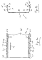
- the assembly channel 10 has a bottom element 12 a flat rear wall 14 and two of the rear wall 14 protruding, in the longitudinal direction 15 of the mounting channel 10 extending side walls 16 (see Fig. 1 and Fig. 2a, 2b).
- the side walls 16 are on the rear wall 14 molded.
- Each side wall 16 has one in Longitudinal direction 15 of the channel 10 extending, convex Bending edge 18 on (dashed line in Fig. 2a), which they in a first, to the rear wall 14th connecting, flat section 20 and a second, Flat portion 22 spaced from rear wall 14 divided.
- the second section 22 is approximately twice as wide - measured from the bending edge 18 to Edge 23 - like the first section 20 - measured from the Rear wall 14 up to the bending edge 18.
- the assembly channel 10 is covered by a Front cover 24, which is a flat front element 26 and two protruding from this front element 26, in Longitudinal direction 15 of the mounting channel 10 extending Has side flanks 28 (cf. FIGS. 1 and 3a, 3b).
- the side flanks 28 are on the front element 26 molded.
- the Side flanks 28 by a in the longitudinal direction 15 of the Mounting channel 10 extending convex bending edge 18 'in a first, adjoining the front element 26, flat flank section 30 and a second, from Front element 26 spaced, flat flank section 32 divided.
- the first flank section 32 - measured from Front element 26 to the bending edge 18 '- is included each slightly wider than the second section 22 of the Sidewall 16.
- the second flank section 32 - measured from the bending edge to the flank edge 29 - is against each about the same width or slightly narrower than that first section 20 of the side wall 16 of the base element 12.
- the side flanks 28 are shaped so that they are in covered condition of the mounting channel 10, as shown in Fig. 1 is shown parallel to the side walls 16, enclose these laterally and each with its second Flank element 32, the convex bending edge 18 of the reach behind the corresponding side wall 16.
- the cross section of the preferred shown The embodiment of the mounting channel 10 is as shown in FIG. 1 is very recognizable, hexagonal. Four of the six pages of this hexagon are through the first sections 20th and second portions 22 of the side walls 16 and through, respectively the first flank sections 30 and second Flank sections 32 of the side flanks 28 are formed. The two remaining sides of the hexagon are covered by the Rear wall 14 or front element 26 of mounting channel 10 educated. The two side walls 16 and two side flanks 28 face each other and are each mirror image to each other.
- the first closes Section 20 of each side wall 16 with the rear wall 14, from Channel interior 33 viewed from, an obtuse angle ⁇ a, which in this example is 120 °.
- obtuse angle ⁇ is closed by the first section 20 and the second section 22 of each side wall 16 one, viewed from the channel interior 33, obtuse angle ⁇ one whose size is chosen so that the second Section 22 to the rear wall 14, again from the channel interior 33 viewed from, arranged at an acute angle ⁇ is.
- the angle has ⁇ a size of 135 ° and angle ⁇ a size of 75 °.
- the Angle ⁇ can however be anywhere between 90 ° ⁇ ⁇ 180 ° vary, with angles between 110 ° and 140 ° particularly are advantageous. The angles ⁇ must then correspond accordingly and ⁇ can be selected.
- the mounting channel 10 is preferably made of sheet metal, molded in particular from stainless steel so that the Side walls 16 and the side flanks 28 are resilient can be deflected. Is used to close the Floor element 12, the front cover 24 on the Bottom element 12 placed, so are the flank edges 29 first on the second sections 22 of the Side walls 16 of the base element 12. When pressing the front cover 24 will be along the second Sections 22 guided and the side flanks 28 are pushed apart. Cross the flank edges 29 the bending edges 18 of the side walls 16 release the tension on the side flanks 28 and the second Flank sections 32 engage behind the bending edge 18 like with a snap lock. Through the parallel Design of the side flanks 28 and side walls 16 they are fed into each other. The resulting one non-positive connection connects the front cover 24 and the bottom member 12 firmly together, such as this is shown in Fig. 1.
- the described hexagonal embodiment is from particularly advantageous for various reasons.
- the special selected, convex shape of the side walls 16 with the Bending edge 18 and the appropriately trained Side flanks 28 of the front cover 24 allow one particularly simple attachment of the front cover 24 am Floor element 14 of the mounting channel 10 via Snap-like, non-positive connection.
- By parallel to each other in the covered state extending side walls 16 and side flanks 28 is a particularly stable connection between the Front cover 24 and the bottom element 12 reached.
- the Shape with hexagonal cross section and mirrored, opposite one another Side walls 16 or side flanks 28 allow one particularly simple and therefore inexpensive manufacture both in sheet metal by bending and, for example, in Injection molding plastic. When running in Plastic, the bending edges 18, 18 'are not bending edges but plastic technology, e.g.
- the side flanks 28 are, as shown in FIG. 3a recognizable by second incisions 38 in Flank segments 40 divided.
- This division allows a bending of the mounting channel 10 perpendicular to Rear wall 14 and thus also a problem-free installation curved walls.
- the type of curvature, convex or concave doesn't matter.
- the stability of the Mounting channel 10 in the direction parallel to the rear wall 14 remains intact.
- FIG. 2a shows, the rear wall 14 of the Bottom element 12 fixing openings 42.
- the mounting channel 10 is easy to fix the openings 42 with the help of screws or similar known Fix fasteners on a wall.
- the rear wall 14 also has fastening eyelets 44 Openings 46 on.
- the eyelets 44 are from the Rear wall 14 against the channel interior 33 of the mounting channel 10, as shown in Figs. 1 and 2b. Their openings 46 are perpendicular to the longitudinal direction 15 of the Mounting channel 10 aligned. You are on the back wall 14 molded.
- the fastening eyes 44 allow one Fixing elongated objects 45 of almost any shape and size in the assembly channel 10.
- Fastening eyes 44 there are also others Fastening options, such as bracket-like holder or similar, for the attachment of the elongated objects 45 possible in assembly channel 10.
- Others are the same Fixing elements as the fixing openings 42 for the Attachment of the mounting channel 10 to the wall is conceivable.
- the mounting channel 10 is not only inexpensive to manufacture and easy to manufacture Assembly, it can also be easily combined with other elements combine that for laying elongated Objects 45 may be necessary.
- 4 is a Mounting channel 10 with base element 12 and front cover 24 combined with a branch 48 on a curved one Inner wall 50 of a tubular shaft 52 shown. During the tap 48 via bracket 54 on the Inner wall 50 of the shaft 52 is attached, this is here shown mounting channel 10 only in the connection area to Indicator through a bracket 54 of the tap 48 co-recorded. Otherwise, it is over its fixing holes 42 attached.
- an anti-kink arrangement 56 e.g.
- the kink protection arrangement 56 is to the right a mounting channel 10, this time in the longitudinal direction 57 of the tube 60 crossing the shaft 52 at its end Inner tube wall 58 is attached.
- the mounting channel 10 is thus an inexpensive and easy to assemble Possibility available, elongated objects 45 relocate. With a special embodiment this not only in the longitudinal direction but also across Longitudinal direction of a pipe or shaft and on irregularly curved walls possible.
Abstract
Description
Die Erfindung betrifft einen Montagekanal zum Verlegen langgestreckter Gegenstände gemäss den Merkmalen des Anspruchs 1.The invention relates to a mounting channel for laying elongated objects according to the characteristics of the Claim 1.
Die Verlegung von Kabeln, Rohren, Lichtleitern und anderen langgestreckten Gegenständen erfolgt heute oft in bereits vorhandenen Schacht- und Kanalisationssystemen, wie z.B. in den Abwasserkanälen einer Gemeinde. In einem Montagekanal für langgestreckte Gegenstände können Rohre, Kabel, Lichtleiter u.ä. problemlos verlegt werden. Ausserdem bietet der Montagekanal auch einen Schutz vor Beschädigungen und vor Verschmutzung. Ist der Montagekanal für eine grössere Anzahl langgestreckter Gegenstände konzipiert, so ist auch ein nachträgliches Einbringen von weiteren langgestreckten Gegenständen problemlos möglich.The laying of cables, pipes, light guides and other elongated objects are often made in today existing shaft and sewer systems, such as. in a community’s sewers. In one Installation channel for elongated objects can be pipes, Cables, light guides, etc. can be easily installed. In addition, the assembly channel also offers protection against Damage and pollution. Is the Mounting channel for a large number of elongated Objects designed, so is an afterthought Introduction of further elongated objects possible without any problems.
Aufgabe der vorliegenden Erfindung ist es, einen Montagekanal zur Verfügung zu stellen, der wirtschaftlich ist in seiner Herstellung und einfach in der Montage.The object of the present invention is a To provide mounting channel that is economical is simple to manufacture and easy to assemble.
Dieses Ziel wird erreicht durch einen Montagekanal gemäss den Merkmalen des Anspruchs 1.This goal is achieved through an assembly channel according to the features of claim 1.
Besonders vorteilhaft ist eine konvexe Ausgestaltung einer zu einem Bodenelement des Montagekanals gehörenden Seitenwand im Zusammenspiel mit einer entsprechend ausgebildeten Seitenflanke einer Frontabdeckung. Durch eine federnde Ausgestaltung der Seitenflanke und/oder der Seitenwand können beide Teile, Seitenwand und Seitenflanke, ineinandergreifen, wobei das eine Teil das andere hintergreift, wodurch zwischen den beiden eine kraftschlüssige Verbindung in der Form eines Schnappverschlusses entsteht. Die Frontabdeckung kann also aufgrund der konvexen Form der Seitenwand und der entsprechenden Ausgestaltung ihrer Seitenflanke mit dem Bodenelement verbunden werden, ohne dass zusätzliche Befestigungselemente an der Frontabdeckung oder dem Bodenelement, z.B. in Form von Nuten, Federn o.ä., angebracht werden müssen. Dadurch ist zum einen die Fertigung des Montagekanals sehr einfach und wirtschaftlich. Zum anderen ist aber auch die Montage des Montagekanals sehr einfach, weil zum Abdecken des Montagekanals die Frontabdeckung nur fest an das Bodenelement angedrückt werden muss.A convex configuration is particularly advantageous one belonging to a floor element of the assembly channel Sidewall in interaction with a corresponding trained side flank of a front cover. By a resilient configuration of the side flank and / or the Sidewall can be both parts, sidewall and Side flank, interlocking, with one part being the engages others, creating one between the two non-positive connection in the form of a Snap lock is created. The front cover can So because of the convex shape of the side wall and the corresponding design of its side flank with the Floor element can be connected without additional Fasteners on the front cover or the Floor element, e.g. in the form of grooves, tongues or similar, must be attached. On the one hand, this is the Manufacturing the assembly channel very easy and economically. On the other hand, the assembly of the Mounting channel very simple because to cover the Mounting channel only firmly to the front cover Floor element must be pressed.
Einen besonderen Vorteil bringt eine Ausgestaltung des
Montagekanals gemäss Anspruch 2. Durch Einschnitte in den
Seitenflanken der Frontabdeckung und in den Seitenwänden
des Bodenelementes jeweils bis wenigstens annähernd an
das Frontelement bzw. an die Rückwand kann der
Montagekanal auch ohne Probleme an gekrümmten Wänden
angebracht werden. Durch die Einschnitte kann er in
Richtung senkrecht zur Rückwand beliebig konvex und
konkav auch abwechselnd konvex und konkav gebogen werden.
Seine Stabilität parallel zur Rückwand bleibt dabei
unangetastet.A design of the
Assembly channel according to
Einen ganz besonderen Vorteil bildet der Montagekanal gemäss Anspruch 7. Zwei mit konvexen Biegekanten versehenen Seitenwände des Bodenelementes bilden zusammen mit entsprechend ausgebildeten Seitenflanken der Frontabdeckung je einen Schnappverschluss. Dadurch lässt sich die Frontabdeckung noch einfacher anbringen und die Herstellung des Montagekanals wird weiter vereinfacht. Wird als Querschnitt des Montagekanals ein Sechseck gewählt ist die Herstellung besonders einfach und der Winkel zwischen den einzelnen Wänden kann so gewählt werden, dass z.B. Wasser gut ablaufen kann, wodurch beispielsweise bei Montagekanälen aus Blech eine Korrosion durch Lachenbildung verhindert wird.The assembly channel is a very special advantage according to claim 7. Two with convex bending edges provided side walls of the floor element form together with appropriately trained side edges of the Front cover each with a snap lock. This leaves the front cover is even easier to attach and the Manufacturing of the assembly channel is further simplified. Is a hexagon as the cross section of the mounting channel the production is particularly simple and selected Angle between the individual walls can be chosen become that e.g. Water can drain well, which means for example, for mounting channels made of sheet metal Corrosion caused by laughter is prevented.
Im weiteren wird die Erfindung anhand der Fig. 1 bis 4a beispielhaft beschrieben. Dabei zeigen schematisch:
- Fig. 1
- im Querschnitt einen sechseckigen Montagekanal;
- Fig. 2a
- ein Bodenelement des Montagekanals aus Fig. 1 in Draufsicht;
- Fig. 2b
- das Bodenelement aus Fig. 2a in Seitenansicht;
- Fig.3a
- eine Frontabdeckung des Montagekanals aus Fig. 1 in Draufsicht
- Fig. 3b
- die Frontabdeckung aus Fig. 3a in Seitenansicht.
- Fig. 4
- den Montagekanal aus den Fig. 1 bis 3b montiert an der Innenwand eines Rohres in dessen Längsrichtung und an einer gekrümmten Wand eines rohrförmigen Schachtes in dessen Umfangsrichtung;
- Fig. 1
- in cross section a hexagonal mounting channel;
- Fig. 2a
- a bottom element of the mounting channel of Figure 1 in plan view.
- Fig. 2b
- the bottom element of Figure 2a in side view.
- Fig.3a
- a front cover of the mounting channel of FIG. 1 in plan view
- Fig. 3b
- the front cover of Fig. 3a in side view.
- Fig. 4
- the mounting channel of Figures 1 to 3b mounted on the inner wall of a tube in its longitudinal direction and on a curved wall of a tubular shaft in its circumferential direction;
Die Fig. 1 bis 3b zeigen eine besonders bevorzugte
Ausführungsform eines erfindungsgemässen Montagekanals
10. Der Montagekanal 10 weist ein Bodenelement 12 mit
einer ebenen Rückwand 14 und mit zwei von der Rückwand 14
abstehenden, sich in Längsrichtung 15 des Montagekanals
10 erstreckenden Seitenwänden 16 auf (vgl. Fig.1 und Fig.
2a, 2b). Die Seitenwände 16 sind an die Rückwand 14
angeformt. Jede Seitenwand 16 weist eine sich in
Längsrichtung 15 des Kanals 10 erstreckende, konvexe
Biegekante 18 auf (gestrichelt gezeichnete Linie in Fig.
2a), die sie in einen ersten, an die Rückwand 14
anschliessenden, ebenen Abschnitt 20 und einen zweiten,
von der Rückwand 14 beabstandeten, ebenen Abschnitt 22
unterteilt. Der zweite Abschnitt 22 ist dabei etwa
doppelt so breit - gemessen von der Biegekante 18 bis zum
Rand 23 - wie der erste Abschnitt 20 - gemessen von der
Rückwand 14 bis zur Biegekante 18.1 to 3b show a particularly preferred
Embodiment of an assembly channel according to the
Abgedeckt ist der Montagekanal 10 durch eine
Frontabdeckung 24, die ein ebenes Frontelement 26 und
zwei von diesem Frontelement 26 abstehende, sich in
Längsrichtung 15 des Montagekanals 10 erstreckende
Seitenflanken 28 aufweist (vgl. Fig. 1 und Fig. 3a, 3b).
Die Seitenflanken 28 sind an das Frontelement 26
angeformt. Wie die Seitenwände 16, so sind auch die
Seitenflanken 28 durch eine sich in Längsrichtung 15 des
Montagekanals 10 erstreckende, konvexe Biegekante 18' in
einen ersten, an das Frontelement 26 anschliessenden,
ebenen Flankenabschnitt 30 und einen zweiten, vom
Frontelement 26 beabstandeten, ebenen Flankenabschnitt 32
unterteilt. Der erste Flankenabschnitt 32 - gemessen vom
Frontelement 26 bis zur Biegekante 18' - ist dabei
jeweils etwas breiter als der zweite Abschnitt 22 der
Seitenwand 16. Der zweite Flankenabschnitt 32 - gemessen
von der Biegekante bis zum Flankenrand 29 - ist dagegen
jeweils etwa gleich breit oder etwas schmäler als der
erste Abschnitt 20 der Seitenwand 16 des Bodenelementes
12. sDie Seitenflanken 28 sind so ausgeformt, dass sie in
abgedecktem Zustand des Montagekanals 10, wie er in Fig.
1 gezeigt ist, parallel zu den Seitenwänden 16 verlaufen,
diese seitlich umfassen und jeweils mit ihrem zweiten
Flankenelement 32 die konvexe Biegekante 18 der
entsprechenden Seitenwand 16 hintergreifen.The
Der Querschnitt der dargestellten, bevorzugten
Ausführungsform des Montagekanals 10 ist, wie aus Fig. 1
sehr gut erkennbar ist, sechseckig. Vier der sechs Seiten
dieses Sechseckes werden durch die ersten Abschnitte 20
und zweiten Abschnitte 22 der Seitenwände 16 bzw. durch
die ersten Flankenabschnitte 30 und zweiten
Flankenabschnitte 32 der Seitenflanken 28 gebildet. Die
zwei verbleibenden Seiten des Sechseckes werden durch die
Rückwand 14 bzw. das Frontelement 26 des Montagekanals 10
gebildet. Dabei liegen die zwei Seitenwände 16 und die
zwei Seitenflanken 28 einander gegenüber und sind jeweils
spiegelbildlich zueinander ausgebildet.The cross section of the preferred shown
The embodiment of the mounting
Wie aus Fig. 2b zu erkennen ist, schlisset der erste
Abschnitt 20 jeder Seitenwand 16 mit der Rückwand 14, vom
Kanalinnenraum 33 aus betrachtet, einen stumpfen Winkel α
ein, der in diesem Beispiel 120° beträgt. Abhängig von
diesem stumpfen Winkel α schliessen der erste Abschnitt
20 und der zweite Abschnitt 22 jeder Seitenwand 16 einen,
vom Kanalinnenraum 33 aus betrachtet, stumpfen Winkel β
ein, dessen Grösse so gewählt ist, dass der zweite
Abschnitt 22 zur Rückwand 14, wiederum vom Kanalinnenraum
33 aus betrachtet, in einem spitzen Winkel γ angeordnet
ist. In dem hier dargestellten Beispiel hat der Winkel β
eine Grösse von 135° und Winkel γ eine Grösse von 75°. Der
Winkel α kann aber beliebig zwischen 90° < α < 180°
variieren, wobei Winkel zwischen 110° und 140° besonders
vorteilhaft sind. Entsprechend müssen dann die Winkel β
und γ gewählt werden.As can be seen from Fig. 2b, the first closes
Der Montagekanal 10 ist vorzugsweise aus Blech,
insbesondere aus rostfreiem Stahl geformt, so dass die
Seitenwände 16 und die Seitenflanken 28 federnd
ausgelenkt werden können. Wird zum verschliessen des
Bodenelementes 12 die Frontabdeckung 24 auf das
Bodenelement 12 aufgesetzt, so stehen die Flankenränder
29 zunächst auf den zweiten Abschnitten 22 der
Seitenwände 16 des Bodenelementes 12 auf. Beim Andrücken
der Frontabdeckung 24 werden sie entlang der zweiten
Abschnitte 22 geführt und die Seitenflanken 28 werden
auseinandergedrückt. Überschreiten die Flankenränder 29
die Biegekanten 18 der Seitenwände 16 lässt die Spannung
auf den Seitenflanken 28 nach und die zweiten
Flankenabschnitte 32 hintergreifen die Biegekante 18 wie
bei einem Schnappverschlusses. Durch die parallele
Ausgestaltung der Seitenflanken 28 und Seitenwände 16
greifen diese satt ineinander. Die so entstehende
kraftschlüssige Verbindung verbindet die Frontabdeckung
24 und das Bodenelement 12 fest miteinander, so wie dies
in Fig. 1 dargestellt ist.The mounting
Die beschriebene sechseckige Ausführungsform ist aus
verschiedenen Gründen besonders vorteilhaft. Die speziell
gewählte, konvexe Form der Seitenwände 16 mit der
Biegekante 18 und den entsprechend ausgebildeten
Seitenflanken 28 der Frontabdeckung 24 ermöglichen ein
besonders einfaches Anbringen der Frontabdeckung 24 am
Bodenelement 14 des Montagekanals 10 via
schnappverschlussähnlicher, kraftschlüssiger Verbindung.
Durch die im abgedeckten Zustand zueinander parallel
verlaufenden Seitenwände 16 und Seitenflanken 28 wird
eine besonders stabile Verbindung zwischen der
Frontabdeckung 24 und dem Bodenelement 12 erreicht. Die
Formgebung mit sechseckigen Querschnitt und
spiegelbildlich ausgebildeten, einander gegenüberliegenden
Seitenwänden 16 bzw. Seitenflanken 28 erlauben eine
besonders einfache und damit kostengünstige Herstellung
sowohl in Blech durch Biegen, als auch beispielsweise in
Kunststoff durch Spritzgiessen. Bei einer Ausführung in
Kunststoff sind die Biegekanten 18, 18' keine Biegekanten
sondern kunststofftechnisch, z.B. durch Spritzguss, geformte
Kanten. Die Art des Kunststoffes und Dicke der
Seitenwände 16 bzw. Seitenflanken 28 müssen dann so
gewählt sein, dass ein Ineinandergreifen der Seitenwände
16 und der Seitenflanken 28 durch eine elastische Auslenkung
möglich ist. Ein weiterer Vorteil der sechseckigen
Ausführungsform liegt in der Anordnung der Seitenwände 16
und der Seitenflanken 28, welche ein problemloses
Ablaufen von Wasser u.ä. gewährleistet.The described hexagonal embodiment is from
particularly advantageous for various reasons. The special
selected, convex shape of the
Wie aus der Fig. 2a ersichtlich, sind die Seitenwände 16
durch erste Einschnitte 34 in zungenartige Segmente 36
unterteilt. Auch die Seitenflanken 28 sind, wie aus Fig.
3a erkennbar durch zweite Einschnitte 38 in
Flankensegmente 40 unterteilt. Diese Unterteilung erlaubt
eine Verbiegung des Montagekanals 10 senkrecht zur
Rückwand 14 und damit auch eine problemlose Montage an
gekrümmten Wänden. Die Art der Krümmung, konvex oder
konkav spielt dabei keine Rolle. Die Stabilität des
Montagekanals 10 in Richtung parallel zur Rückwand 14
bleibt dabei erhalten.As can be seen from FIG. 2a, the
Wie Fig. 2a zeigt, weist die Rückwand 14 des
Bodenelementes 12 Fixieröffnungen 42 auf. Über diese
Fixieröffnungen 42 lässt sich der Montagekanal 10 einfach
mit Hilfe von Schrauben oder ähnlichen bekannten
Befestigungselementen an einer Wand fixieren. Des
weiteren weist die Rückwand 14 Befestigungsösen 44 mit
Öffnungen 46 auf. Die Befestigungsösen 44 stehen von der
Rückwand 14 gegen den Kanalinnenraum 33 des Montagekanals
10 ab, wie dies in den Fig. 1 und 2b dargestellt ist.
Ihre Öffnungen 46 sind senkrecht zur Längsrichtung 15 des
Montagekanals 10 ausgerichtet. Sie sind an die Rückwand
14 angeformt. Die Befestigungsösen 44 erlauben ein
Fixieren von langgestreckten Gegenständen 45 von nahezu
beliebiger Form und Grösse im Montagekanal 10. Zu ihrer
Befestigung müssen nur entsprechende Befestigungsmittel
47, wie z.B. Kabelbinder, durch die Befestigungsösen 44
hindurchgeführt und festgezogen werden, so wie dies in
Fig. 1 dargestellt ist. Als langgestreckte Gegenstände 45
sind in Fig. 1 drei kleine Rohre dargestellt, in denen je
z.B. Lichtleiterkabel oder aber auch fluide Medien
geführt sein können. Neben diesen einfachen
Montagemöglichkeiten erlaubt die Ausgestaltung der
Fixieröffnungen 42 und der an die Rückwand 14 angeformten
Befestigungsösen 44 eine einfache und kostengünstige
Herstellung des Montagekanals 10, z.B. durch Stanzen und
Biegen und evtl. Tiefziehen von Blechen.2a shows, the
Neben der beschriebenen Ausführungsform mit sechseckigem
Querschnitt sind natürlich auch Ausführungen des
Montagekanals 10 denkbar, bei denen die Seitenwände 16
mehr als nur eine Biegekante 18 aufweisen und der
Querschnitt mehr als sechs Ecken zeigt; oder Formen, bei
denen die Seitenwände 16 in Form von Kreissegmenten
ausgestaltet sind. Auch nicht spiegelsymmetrische
Ausführungsformen sind denkbar und Ausführungsformen, bei
denen nur eine Seitenwand 16 in der beschriebenen
konvexen Form ausgebildet ist. Dementsprechend weist dann
auch die Frontabdeckung 12 nur eine Seitenflanke 28 auf
und die kraftschlüssige, schnappverschlussartige
Verbindung wird nur an dieser einen Seitenwand 16
ausgebildet. Statt, dass die Seitenflanken 28 der
Frontabdeckung 24 die Seitenwände 16 aussen, seitlich
umgreifen, wie dies in Fig. 1 dargestellt ist, ist auch
denkbar, dass die Seitenwände 16 die Seitenflanken 28
aussen, seitlich umgreifen.In addition to the described embodiment with hexagonal
Cross section are of course also versions of the
Mounting
Anstelle der Befestigungsösen 44 sind auch andere
Befestigungsmöglichkeiten, wie z.B. klammerartige Halter
o.ä., für die Befestigung der langgestreckten Gegenstände
45 im Montagekanal 10 möglich. Ebenso sind andere
Fixierelemente als die Fixieröffnungen 42 für die
Befestigung des Montagekanals 10 an der Wand denkbar. Instead of the
Durch seine einfache Bauart ist der Montagekanal 10 nicht
nur kostengünstig in der Herstellung und einfach in der
Montage, er lässt sich auch leicht mit anderen Elementen
kombinieren, die zum Verlegen von langgestreckten
Gegenständen 45 nötig sein können. In Fig. 4 ist ein
Montagekanal 10 mit Bodenelement 12 und Frontabdeckung 24
kombiniert mit einem Abzweiger 48 an einer gekrümmten
Innenwand 50 eines rohrförmigen Schachtes 52 dargestellt.
Während der Abzweiger 48 über Haltebügel 54 an der
Innenwand 50 des Schachtes 52 befestigt ist, ist der hier
gezeigte Montagekanal 10 nur im Anschlussbereich zum
Abzeiger durch einen Haltebügel 54 des Abzweigers 48
miterfasst. Ansonsten ist er über seine Fixieröffnungen
42 befestigt. Auf der dem Montagekanal 10
gegenüberliegenden Seite des Abzweigers 48 schliesst sich
eine Knickschutzanordnung 56 an, wie sie z.B. für
Glasfaserkabel eingesetzt wird und wie sie beispielsweise
in der Anmeldung Vertreternummer A12709ep beschrieben
ist. An die Knickschutzanordnung 56 schliesst sich rechts
ein Montagekanal 10 an, der diesmal in Längsrichtung 57
des den Schacht 52 kreuzenden Rohres 60 an dessen
Rohrinnenwand 58 befestigt ist.Due to its simple design, the mounting
Mit dem erfindungsgemässen Montagekanal 10 steht also
eine kostengünstige und in der Montage einfache
Möglichkeit zur Verfügung, langgestreckte Gegenstände 45
zu Verlegen. Mit einer speziellen Ausführungsform ist
dies nicht nur in Längsrichtung sondern auch quer zur
Längsrichtung eines Rohres oder Schachtes und auf
unregelmässig gekrümmten Wänden möglich.With the mounting
Claims (11)
Priority Applications (1)
| Application Number | Priority Date | Filing Date | Title |
|---|---|---|---|
| EP98123946A EP1011181A1 (en) | 1998-12-17 | 1998-12-17 | Mounting channel |
Applications Claiming Priority (1)
| Application Number | Priority Date | Filing Date | Title |
|---|---|---|---|
| EP98123946A EP1011181A1 (en) | 1998-12-17 | 1998-12-17 | Mounting channel |
Publications (1)
| Publication Number | Publication Date |
|---|---|
| EP1011181A1 true EP1011181A1 (en) | 2000-06-21 |
Family
ID=8233153
Family Applications (1)
| Application Number | Title | Priority Date | Filing Date |
|---|---|---|---|
| EP98123946A Withdrawn EP1011181A1 (en) | 1998-12-17 | 1998-12-17 | Mounting channel |
Country Status (1)
| Country | Link |
|---|---|
| EP (1) | EP1011181A1 (en) |
Cited By (6)
| Publication number | Priority date | Publication date | Assignee | Title |
|---|---|---|---|---|
| US6712556B2 (en) | 2001-05-18 | 2004-03-30 | G. Gregory Penza | Method and apparatus for routing cable in existing pipelines |
| US7004681B2 (en) | 2001-05-18 | 2006-02-28 | Penza G Gregory | Method and apparatus for routing cable in existing pipelines |
| DE102004042590B4 (en) * | 2003-09-02 | 2007-04-26 | Yazaki Corp. | casing |
| NL2010478C2 (en) * | 2013-03-19 | 2014-09-24 | Walraven Holding Bv J Van | Support channel for a pipe. |
| EP2781814A1 (en) * | 2013-03-19 | 2014-09-24 | J. van Walraven Holding B.V. | Support channel |
| WO2017168023A1 (en) * | 2016-03-30 | 2017-10-05 | Unex Aparellaje Electrico S.L. | Channel assembly for fluid ducts |
Citations (2)
| Publication number | Priority date | Publication date | Assignee | Title |
|---|---|---|---|---|
| CH368844A (en) * | 1958-06-07 | 1963-04-30 | Theysohn Albert | Cable duct |
| EP0746074A2 (en) * | 1992-11-04 | 1996-12-04 | Herman Miller, Inc. | Raceway cable retention and accommodation apparatus |
-
1998
- 1998-12-17 EP EP98123946A patent/EP1011181A1/en not_active Withdrawn
Patent Citations (2)
| Publication number | Priority date | Publication date | Assignee | Title |
|---|---|---|---|---|
| CH368844A (en) * | 1958-06-07 | 1963-04-30 | Theysohn Albert | Cable duct |
| EP0746074A2 (en) * | 1992-11-04 | 1996-12-04 | Herman Miller, Inc. | Raceway cable retention and accommodation apparatus |
Cited By (8)
| Publication number | Priority date | Publication date | Assignee | Title |
|---|---|---|---|---|
| US6712556B2 (en) | 2001-05-18 | 2004-03-30 | G. Gregory Penza | Method and apparatus for routing cable in existing pipelines |
| US7004681B2 (en) | 2001-05-18 | 2006-02-28 | Penza G Gregory | Method and apparatus for routing cable in existing pipelines |
| DE102004042590B4 (en) * | 2003-09-02 | 2007-04-26 | Yazaki Corp. | casing |
| NL2010478C2 (en) * | 2013-03-19 | 2014-09-24 | Walraven Holding Bv J Van | Support channel for a pipe. |
| EP2781814A1 (en) * | 2013-03-19 | 2014-09-24 | J. van Walraven Holding B.V. | Support channel |
| WO2017168023A1 (en) * | 2016-03-30 | 2017-10-05 | Unex Aparellaje Electrico S.L. | Channel assembly for fluid ducts |
| CN108884959A (en) * | 2016-03-30 | 2018-11-23 | 乌尼克斯·阿帕里拉杰电子有限公司 | Channel components for fluid line |
| CN108884959B (en) * | 2016-03-30 | 2020-10-23 | 乌尼克斯·阿帕里拉杰电子有限公司 | Channel assembly for fluid conduits |
Similar Documents
| Publication | Publication Date | Title |
|---|---|---|
| EP0428896B1 (en) | Fastening system | |
| EP1729386A2 (en) | Line fixation device | |
| CH618251A5 (en) | ||
| DE3636412C2 (en) | Connection of cable ducts arranged opposite each other at the end | |
| DE202005004522U1 (en) | Pipe coupling | |
| DE4435177C2 (en) | Holder system for pipes or the like | |
| DE102015008877A1 (en) | Modular sliding or tensioning rail | |
| AT505430B1 (en) | CABLE CHANNEL AND SOFT | |
| EP0404726B1 (en) | Device for connecting c-shaped rails, especially mounting rails | |
| EP1587195A2 (en) | Cable channel system | |
| EP1516402A1 (en) | Cable holding device | |
| EP1011181A1 (en) | Mounting channel | |
| EP1884702B1 (en) | Bracket for attaching restiform components | |
| DE202021101741U1 (en) | Flat duct arrangement for a downdraft extractor hood | |
| DE202005016947U1 (en) | Connector for channel-shaped profile bars and connection arrangement | |
| DE19944060B4 (en) | Device for kink protection of optical cables | |
| DE102008045869A1 (en) | Cable or flexible tube guiding and holding device for use in e.g. electrical and electronic component, has fastening sides arranged opposite to each other, and receivers twisted against both fastening sides with respect to orientation | |
| DE3017317A1 (en) | SPACERS | |
| EP1746322B1 (en) | Clamp for fixing at least one conduit | |
| DE102013201988A1 (en) | Fastening arrangement for attachment of device to support structure, has coupling projection that is movable in engagement coupling direction in coupling recess for manufacturing of coupling state between coupling region and feedback area | |
| DE202020101104U1 (en) | Pipe clamp and construction kit for their creation | |
| DE19600931A1 (en) | Wall plug for anchoring e.g. screw or similar component in a wall | |
| DE4312340A1 (en) | Dowel | |
| DE3518813A1 (en) | FLANGE FOR FASTENING TUBES | |
| EP1398555A1 (en) | Wear ring to be placed on a pipe, hose, cable or the like and corrugated pipe assembly incorporating said wear ring |
Legal Events
| Date | Code | Title | Description |
|---|---|---|---|
| PUAI | Public reference made under article 153(3) epc to a published international application that has entered the european phase |
Free format text: ORIGINAL CODE: 0009012 |
|
| AK | Designated contracting states |
Kind code of ref document: A1 Designated state(s): AT BE CH CY DE DK ES FI FR GB GR IE IT LI LU MC NL PT SE |
|
| AX | Request for extension of the european patent |
Free format text: AL;LT;LV;MK;RO;SI |
|
| AKX | Designation fees paid | ||
| STAA | Information on the status of an ep patent application or granted ep patent |
Free format text: STATUS: THE APPLICATION IS DEEMED TO BE WITHDRAWN |
|
| 18D | Application deemed to be withdrawn |
Effective date: 20001222 |