EP1010918A2 - Verfahren zur Verschliessreduzierung für kontinuierlich arbeitende Maschinen - Google Patents
Verfahren zur Verschliessreduzierung für kontinuierlich arbeitende Maschinen Download PDFInfo
- Publication number
- EP1010918A2 EP1010918A2 EP99310072A EP99310072A EP1010918A2 EP 1010918 A2 EP1010918 A2 EP 1010918A2 EP 99310072 A EP99310072 A EP 99310072A EP 99310072 A EP99310072 A EP 99310072A EP 1010918 A2 EP1010918 A2 EP 1010918A2
- Authority
- EP
- European Patent Office
- Prior art keywords
- variable geometry
- rings
- relative motion
- engine
- stand
- Prior art date
- Legal status (The legal status is an assumption and is not a legal conclusion. Google has not performed a legal analysis and makes no representation as to the accuracy of the status listed.)
- Withdrawn
Links
- 238000000034 method Methods 0.000 title claims abstract description 17
- 238000013016 damping Methods 0.000 claims abstract description 20
- 239000002131 composite material Substances 0.000 claims description 3
- 230000005540 biological transmission Effects 0.000 abstract 1
- 238000006073 displacement reaction Methods 0.000 description 7
- 230000008901 benefit Effects 0.000 description 5
- 230000006872 improvement Effects 0.000 description 4
- VNWKTOKETHGBQD-UHFFFAOYSA-N methane Chemical compound C VNWKTOKETHGBQD-UHFFFAOYSA-N 0.000 description 4
- 239000000446 fuel Substances 0.000 description 3
- 230000000694 effects Effects 0.000 description 2
- 239000000463 material Substances 0.000 description 2
- 239000003345 natural gas Substances 0.000 description 2
- 230000008859 change Effects 0.000 description 1
- 239000000314 lubricant Substances 0.000 description 1
- 238000012986 modification Methods 0.000 description 1
- 230000004048 modification Effects 0.000 description 1
- 230000002028 premature Effects 0.000 description 1
Images


Classifications
-
- F—MECHANICAL ENGINEERING; LIGHTING; HEATING; WEAPONS; BLASTING
- F16—ENGINEERING ELEMENTS AND UNITS; GENERAL MEASURES FOR PRODUCING AND MAINTAINING EFFECTIVE FUNCTIONING OF MACHINES OR INSTALLATIONS; THERMAL INSULATION IN GENERAL
- F16F—SPRINGS; SHOCK-ABSORBERS; MEANS FOR DAMPING VIBRATION
- F16F15/00—Suppression of vibrations in systems; Means or arrangements for avoiding or reducing out-of-balance forces, e.g. due to motion
- F16F15/02—Suppression of vibrations of non-rotating, e.g. reciprocating systems; Suppression of vibrations of rotating systems by use of members not moving with the rotating systems
- F16F15/04—Suppression of vibrations of non-rotating, e.g. reciprocating systems; Suppression of vibrations of rotating systems by use of members not moving with the rotating systems using elastic means
-
- F—MECHANICAL ENGINEERING; LIGHTING; HEATING; WEAPONS; BLASTING
- F16—ENGINEERING ELEMENTS AND UNITS; GENERAL MEASURES FOR PRODUCING AND MAINTAINING EFFECTIVE FUNCTIONING OF MACHINES OR INSTALLATIONS; THERMAL INSULATION IN GENERAL
- F16F—SPRINGS; SHOCK-ABSORBERS; MEANS FOR DAMPING VIBRATION
- F16F7/00—Vibration-dampers; Shock-absorbers
- F16F7/10—Vibration-dampers; Shock-absorbers using inertia effect
- F16F7/104—Vibration-dampers; Shock-absorbers using inertia effect the inertia member being resiliently mounted
Definitions
- the present invention relates in general to engine operation and more particularly to a system and method for minimizing the relative motion at hardware interfaces of continuously operating engine systems.
- Multitude existing engines such as aircraft engines, and also including automobile, marine, industrial and other engines, have multiple locations of relative motion. Relative motion exists everywhere adjacent hardware is linked with bearings or is bushed. When the engine is run continuously, even small displacements will wear at the linked or bushed interfaces. Current systems have high responses at the interfaces due to a match in natural frequencies and normal engine vibrations. Normal engine vibrations which are common to flight engines are those vibrations induced by rotating hardware
- vibrations may be caused from natural gas fuel. Natural gas is readily available and is the fuel of choice for most operators. This phenomenon is called combustor rumble. Combustor rumble imparts energy to the variable geometry system and is absorbed and damped at the linkage bearings and bushed interfaces.
- Some engines can experience fleet-wide premature wear of high pressure compressor variable geometry hardware.
- the system wear is responsible for several undesirable conditions, such as unscheduled downtime to replace worn hardware; loose links from worn bearings; operational problems including reduced stall margin and degraded specific fuel consumption (SFC); and stage 2 high pressure compressor shroud and blade contact.
- SFC specific fuel consumption
- the current replacement rate of the high pressure compressor variable geometry hardware is between 8000 and 10000 hours, which is about equal to 15 months of field service.
- the expected durability of the variable geometry system is about 4-5 years.
- Several changes have been introduced in the art to improve component durability such as improved materials, anti-rotation features on bushings and lubricants in areas of relative motion between rubbing hardware and larger bearings in the links.
- these improvements are introduced as incremental improvements to make the hardware more tolerant of the engine system vibrations.
- variable geometry system responds at resonant frequencies from normal engine vibrations. This results in extreme relative motion at the hardware connecting interfaces and has a significant impact on the service capability of the hardware.
- the present invention provides for system life improvement of an engine by addressing the tendency of the hardware to deteriorate from resonating at their natural frequencies.
- relative motion at hardware interfaces of an engine system are minimized by de-tuning and damping the existing hardware from typical engine vibrations and combustor rumble.
- the present invention proposes a system and method for minimizing the relative motion at hardware interfaces of an engine system 40, illustrated in Fig. 1.
- multiple locations exist for relative motion, everywhere adjacent hardware is linked with bearings or is bushed.
- link 1, 2 and 3 connect unison rings 4, 5 and 6, respectively, to master lever 9.
- vane spindle bushings 22 wear from rubs at the vane spindle 16, 17 and 18 and casing 37 surface.
- Unison ring bushings 29 wear from rubs between the lever arm pin 26, 27 and 28 and the unison ring 4, 5 and 6 surfaces.
- the inner shroud bushings 19, 20 and 21, shrouds 12, 13 and 14 and retaining pins 15 wear from rubs with adjacent hardware. When the engine is run continuously, even small displacements will wear at the linked or bushed interfaces.
- variable geometry system adjusts the angle of the variable vanes 16, 17 and 18 to direct the airflow onto rotating airfoils (not shown).
- the purpose of directing the air is to maintain aerodynamic loads within the mechanical limits of the airfoil and to achieve efficiency and stall margin requirements for safe and reliable operation.
- an electronically controlled actuator positions outer bellcrank 34 to schedule the variable vanes.
- the outer bellcrank 34 translates the linear motion of the actuator to an angular displacement, which is converted to linear displacements at the master lever 9 and links 1, 2 and 3.
- the linear displacement of the links rotate the unison rings 4, 5 and 6.
- Lever arms 26, 27 and 28 convert the rotational displacement of the rings to an angular displacement of the variable vanes.
- the relative motion at the hardware interfaces is minimized by de-tuning and damping the existing hardware, such as is shown in Fig. 1, from typical engine vibrations and combustor rumbles. Minimization of relative motion can be accomplished by loading the variable geometry rings 4, 5 and 6 with a force in the radial direction shown by arrow R.
- this force is achieved with a spring, for example item 50 in Fig. 2A, located between the rings 4, 5 and 6 and corresponding stand-off pads 23, 24 and 25 in Fig. 1.
- the springs 50 change the natural frequencies of the rings 4, 5 and 6 in Fig. 1 and provide frictional damping at the stand-off pads 23, 24 and 25 and casing 37, or can provide independent radial damping.
- one alternative embodiment for minimization of relative motion by loading the variable geometry rings in the radial direction with a force proposes a force comprised of a helical conic spring 52 disposed around a ring stud 7, as illustrated in Fig. 2B.
- a force comprised of a helical conic spring 52 disposed around a ring stud 7, as illustrated in Fig. 2B.
- An additional benefit provided by the present invention is that frictional damping at the interface between the stand-off pads 23, 24 and 25 and casing 37 in Fig. 1 results in a reduced relative motion between the rings 4, 5 and 6 in Fig. 1 and the adjacent hardware such as, for example, at the connecting links 1, 2 and 3, master lever 9, inner bellcrank 10, forward mount 11, aft mount 8, and lever arm pin bushings 29 in Fig. 1.
- the benefit of damping is inherited by other components within the variable geometry system that are affected by the unison ring 4, 5 and 6 motion such as, for example, the variable vane spindle bushings 22, shroud bushings 19, 20 and 21, and retaining pins 15 as shown in Fig. 1.
- Fig. 2C Another alternative embodiment is illustrated in Fig. 2C, wherein a helical conic segment of rubber 54 is applied to the ring stud 7.
- the inherent damping properties of rubber provide an advantage by absorbing energy from vibrations that would otherwise be transmitted through the variable geometry system.
- the rubber material is resistant to breakage and is insulated from the hot casing 37 while the engine is running, at the interface between the stand-off pad 23, 24 and 25 and the casing 37.
- the present invention utilizes the insulating properties of the stand-off pad by having the stand-off pad provide a physical boundary between the case 37 and the rubber damper, consequently insulating the rubber from the casing 37.
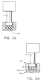
- Fig. 2D illustrates an embodiment wherein a thin washer spring 56 is embedded into the stand-off pad, with that section shown enlarged. With this configuration, the springs 56 can be integrated into the stand-off pad 23, 24, and 25 of Fig. 1, for interchangeability advantages.
- a wide washer spring 58 is embedded into stand-off pad 23, 24 and 25.
- springs 58 can be integrated into the stand-off pads during assembly. Since spring 58 is wider than spring 56 of Fig. 2D, stand-off pad wear will have less effect on spring load in the embodiment of Fig. 2E.
- Fig. 2F proposes a thin elastomeric insert 60 embedded into stand-off pad 23, 24 and 25.
- One advantage of this embodiment is that the inserts 60 can be integrated into the stand-off pads during assembly.
- the elastomeric insert 60 is contained within its location and provides advantageous damping properties by absorbing energy from vibrations that would otherwise be transmitted through the variable geometry system.
- FIG. 2G illustrates a wide elastomeric insert 62 embedded in stand-off pad 23, 24, 25. Again, the elastomeric pad 62 is contained and can be integrated into the stand-off pads. Since elastomeric insert 62 is wider than elastomeric insert 60 of Fig. 2F, stand-off pad wear will have less effect on radial load and damping in the embodiment of Fig. 2G.
- a metallic stand-off pad 64 is proposed.
- the metallic stand-off pad 64 protects the casing 37 from spring 66 contact should the said spring penetrate through the stand-off pad 23, 24, 25 in Fig. 1.
- a composite rub surface 68 is added at the interface between the stand-off pad 23, 24, 25, and casing 37 in Fig. 1, to minimize wear at said stand-off pad and casing interface.
Landscapes
- Engineering & Computer Science (AREA)
- General Engineering & Computer Science (AREA)
- Mechanical Engineering (AREA)
- Physics & Mathematics (AREA)
- Acoustics & Sound (AREA)
- Aviation & Aerospace Engineering (AREA)
- Structures Of Non-Positive Displacement Pumps (AREA)
- Control Of Turbines (AREA)
- Turbine Rotor Nozzle Sealing (AREA)
Applications Claiming Priority (2)
| Application Number | Priority Date | Filing Date | Title |
|---|---|---|---|
| US215859 | 1988-07-06 | ||
| US09/215,859 US6092984A (en) | 1998-12-18 | 1998-12-18 | System life for continuously operating engines |
Publications (2)
| Publication Number | Publication Date |
|---|---|
| EP1010918A2 true EP1010918A2 (de) | 2000-06-21 |
| EP1010918A3 EP1010918A3 (de) | 2003-01-29 |
Family
ID=22804701
Family Applications (1)
| Application Number | Title | Priority Date | Filing Date |
|---|---|---|---|
| EP99310072A Withdrawn EP1010918A3 (de) | 1998-12-18 | 1999-12-15 | Verfahren zur Verschliessreduzierung für kontinuierlich arbeitende Maschinen |
Country Status (3)
| Country | Link |
|---|---|
| US (1) | US6092984A (de) |
| EP (1) | EP1010918A3 (de) |
| JP (1) | JP2000199403A (de) |
Cited By (6)
| Publication number | Priority date | Publication date | Assignee | Title |
|---|---|---|---|---|
| EP1205639A1 (de) * | 2000-11-09 | 2002-05-15 | General Electric Company | Befestigungsanordnung von verstellbaren Turbinenleitschaufeln im inneren Haltering |
| EP1818509A1 (de) * | 2006-02-09 | 2007-08-15 | Siemens Aktiengesellschaft | Leitapparat und Dämpfelement für einen Leitapparat |
| EP2037085A1 (de) * | 2007-09-13 | 2009-03-18 | Snecma | Lever for variable stator vanes of a turbomachine |
| EP1529926A3 (de) * | 2003-11-04 | 2012-08-22 | General Electric Company | Feder-Dämpfer-System für ein Turbinendeckband |
| EP3000985A1 (de) * | 2014-09-29 | 2016-03-30 | Rolls-Royce North American Technologies, Inc. | Verstellring-selbstzentrierer und verfahren zur zentralisierung |
| EP3085967A4 (de) * | 2013-12-19 | 2017-09-06 | Kawasaki Jukogyo Kabushiki Kaisha | Mechanismus für verstellbare leitschaufel |
Families Citing this family (8)
| Publication number | Priority date | Publication date | Assignee | Title |
|---|---|---|---|---|
| FR2856424B1 (fr) * | 2003-06-20 | 2005-09-23 | Snecma Moteurs | Dispositif de calage variable de deux etages d'aubes fixes sur un turboreacteur |
| DE102005040574A1 (de) * | 2005-08-26 | 2007-03-15 | Rolls-Royce Deutschland Ltd & Co Kg | Spaltkontrollvorrichtung für eine Gasturbine |
| FR2897121B1 (fr) * | 2006-02-09 | 2008-05-02 | Snecma Sa | Dispositif de reglage du centrage d'un anneau de synchronisation de commande d'aubes pivotantes de turbomachine |
| US10161407B2 (en) | 2013-06-14 | 2018-12-25 | United Technologies Corporation | Radial fastening of tubular synchronizing rings |
| GB201614803D0 (en) * | 2016-09-01 | 2016-10-19 | Rolls Royce Plc | Variable stator vane rigging |
| FR3077851B1 (fr) * | 2018-02-09 | 2020-01-17 | Safran Aircraft Engines | Ensemble de commande d'un etage d'aubes a calage variable pour une turbomachine |
| US11346240B2 (en) * | 2019-06-07 | 2022-05-31 | Raytheon Technologies Corporation | Gas turbine engine bleed valve damping guide link |
| US11560810B1 (en) * | 2021-07-20 | 2023-01-24 | Rolls-Royce North American Technologies Inc. | Variable vane actuation system and method for gas turbine engine performance management |
Family Cites Families (10)
| Publication number | Priority date | Publication date | Assignee | Title |
|---|---|---|---|---|
| US2842305A (en) * | 1955-11-01 | 1958-07-08 | Gen Electric | Compressor stator assembly |
| US3303992A (en) * | 1965-03-03 | 1967-02-14 | Gen Motors Corp | Variable vane stator ring |
| US3314595A (en) * | 1965-06-09 | 1967-04-18 | Gen Electric | Adjustment mechanism for axial flow compressors |
| US4050844A (en) * | 1976-06-01 | 1977-09-27 | United Technologies Corporation | Connection between vane arm and unison ring in variable area stator ring |
| CA1034509A (en) * | 1975-10-14 | 1978-07-11 | John Korta | Vane rotator assembly for a gas turbine |
| JPS6056276B2 (ja) * | 1978-10-20 | 1985-12-09 | 株式会社日立製作所 | ガイドベ−ン保護装置 |
| FR2608678B1 (fr) * | 1986-12-17 | 1991-02-08 | Snecma | Dispositif de commande d'aubes a calage variable de redresseur de turbomachine |
| DE3711224A1 (de) * | 1987-04-03 | 1988-10-13 | Gutehoffnungshuette Man | Verstelleinrichtung fuer die leitschaufeln einer axialstroemungsmaschine |
| DE4329014C1 (de) * | 1993-08-28 | 1995-01-05 | Mtu Muenchen Gmbh | Rotorgehäuse, insbesondere Gehäuse für Turbotriebwerke |
| US5601401A (en) * | 1995-12-21 | 1997-02-11 | United Technologies Corporation | Variable stage vane actuating apparatus |
-
1998
- 1998-12-18 US US09/215,859 patent/US6092984A/en not_active Expired - Fee Related
-
1999
- 1999-11-30 JP JP11339118A patent/JP2000199403A/ja not_active Withdrawn
- 1999-12-15 EP EP99310072A patent/EP1010918A3/de not_active Withdrawn
Non-Patent Citations (1)
| Title |
|---|
| None |
Cited By (12)
| Publication number | Priority date | Publication date | Assignee | Title |
|---|---|---|---|---|
| EP1205639A1 (de) * | 2000-11-09 | 2002-05-15 | General Electric Company | Befestigungsanordnung von verstellbaren Turbinenleitschaufeln im inneren Haltering |
| EP1529926A3 (de) * | 2003-11-04 | 2012-08-22 | General Electric Company | Feder-Dämpfer-System für ein Turbinendeckband |
| EP1818509A1 (de) * | 2006-02-09 | 2007-08-15 | Siemens Aktiengesellschaft | Leitapparat und Dämpfelement für einen Leitapparat |
| WO2007090731A3 (de) * | 2006-02-09 | 2007-11-15 | Siemens Ag | Leitapparat und dämpfelement für einen leitapparat |
| EP2037085A1 (de) * | 2007-09-13 | 2009-03-18 | Snecma | Lever for variable stator vanes of a turbomachine |
| FR2921100A1 (fr) * | 2007-09-13 | 2009-03-20 | Snecma Sa | Levier d'entrainement en rotation autour de son pivot d'aube de stator a calage variable de turbomachine |
| US8197190B2 (en) | 2007-09-13 | 2012-06-12 | Snecma | Lever for rotating a turbomachine variable-pitch stator vane about its pivot |
| RU2471077C2 (ru) * | 2007-09-13 | 2012-12-27 | Снекма | Рычаг приведения во вращение вокруг поворотной оси лопатки статора турбомашины с изменяемым углом установки |
| EP3085967A4 (de) * | 2013-12-19 | 2017-09-06 | Kawasaki Jukogyo Kabushiki Kaisha | Mechanismus für verstellbare leitschaufel |
| US10364828B2 (en) | 2013-12-19 | 2019-07-30 | Kawasaki Jukogyo Kabushiki Kaisha | Variable stator vane mechanism |
| EP3000985A1 (de) * | 2014-09-29 | 2016-03-30 | Rolls-Royce North American Technologies, Inc. | Verstellring-selbstzentrierer und verfahren zur zentralisierung |
| US10184350B2 (en) | 2014-09-29 | 2019-01-22 | Rolls-Royce North American Technologies, Inc. | Unison ring self-centralizers and method of centralizing |
Also Published As
| Publication number | Publication date |
|---|---|
| US6092984A (en) | 2000-07-25 |
| EP1010918A3 (de) | 2003-01-29 |
| JP2000199403A (ja) | 2000-07-18 |
Similar Documents
| Publication | Publication Date | Title |
|---|---|---|
| US6092984A (en) | System life for continuously operating engines | |
| JP5142061B2 (ja) | 可変ピッチステータ翼用の軸受 | |
| US6224533B1 (en) | Flexible metal supporting device for a centrifugal separator | |
| US2999630A (en) | Compressor | |
| EP1741878B1 (de) | Strömungsmaschine | |
| JP5126505B2 (ja) | 可変ピッチブレードの制御 | |
| US6139261A (en) | Bushing assembly with removable wear sleeve | |
| CN1982675B (zh) | 可变定子叶片装置及其衬套 | |
| EP1024252B1 (de) | Werkstoffe für Dichtungen und Beilagscheiben von verstellbaren Leitschaufeln | |
| US20050008489A1 (en) | Antiwear device for a variable pitch system for a turbomachine vane | |
| EP1428986B1 (de) | Lageranordnung für ein Torsionsrohr | |
| GB2058245A (en) | Alleviating abnormal loadings in bearings | |
| US20040240991A1 (en) | Variable stator vane bushings and washers | |
| US11421534B2 (en) | Damping device | |
| US11346233B2 (en) | Damping device | |
| RU2691000C1 (ru) | Автоматическое устройство термомеханического управления радиальным зазором между концами рабочих лопаток ротора и статора компрессора или турбины газотурбинного двигателя | |
| US6106227A (en) | Roller assembly for guiding an actuating ring | |
| KR0147691B1 (ko) | 기울어짐 보정기능을 가진 축장착부 | |
| US11466571B1 (en) | Damping device | |
| US11536157B2 (en) | Damping device | |
| US20220307603A1 (en) | Non-contact seal assembly with damping elements | |
| US10934884B2 (en) | Assembly for a turbine engine | |
| CN114278435A (zh) | 压气机、燃气涡轮发动机、可调静叶组件以及装配方法 | |
| EP4015777B1 (de) | Bypass-kanalverkleidungsinstallation eines gasturbinentriebwerkes | |
| CN210152745U (zh) | 一种发动机调节机构摇臂支撑结构及航空发动机 |
Legal Events
| Date | Code | Title | Description |
|---|---|---|---|
| PUAI | Public reference made under article 153(3) epc to a published international application that has entered the european phase |
Free format text: ORIGINAL CODE: 0009012 |
|
| AK | Designated contracting states |
Kind code of ref document: A2 Designated state(s): AT BE CH CY DE DK ES FI FR GB GR IE IT LI LU MC NL PT SE |
|
| AX | Request for extension of the european patent |
Free format text: AL;LT;LV;MK;RO;SI |
|
| PUAL | Search report despatched |
Free format text: ORIGINAL CODE: 0009013 |
|
| AK | Designated contracting states |
Designated state(s): AT BE CH CY DE DK ES FI FR GB GR IE IT LI LU MC NL PT SE |
|
| AX | Request for extension of the european patent |
Extension state: AL LT LV MK RO SI |
|
| RIC1 | Information provided on ipc code assigned before grant |
Ipc: 7F 01D 9/04 B Ipc: 7F 01D 17/16 B Ipc: 7F 16F 15/04 A |
|
| 17P | Request for examination filed |
Effective date: 20030729 |
|
| AKX | Designation fees paid |
Designated state(s): DE FR GB |
|
| 17Q | First examination report despatched |
Effective date: 20040326 |
|
| STAA | Information on the status of an ep patent application or granted ep patent |
Free format text: STATUS: THE APPLICATION IS DEEMED TO BE WITHDRAWN |
|
| 18D | Application deemed to be withdrawn |
Effective date: 20040806 |