EP1010889A2 - Engine air intake manifold having built-in intercooler - Google Patents
Engine air intake manifold having built-in intercooler Download PDFInfo
- Publication number
- EP1010889A2 EP1010889A2 EP99124574A EP99124574A EP1010889A2 EP 1010889 A2 EP1010889 A2 EP 1010889A2 EP 99124574 A EP99124574 A EP 99124574A EP 99124574 A EP99124574 A EP 99124574A EP 1010889 A2 EP1010889 A2 EP 1010889A2
- Authority
- EP
- European Patent Office
- Prior art keywords
- engine
- intake manifold
- intercooler
- manifold
- air
- Prior art date
- Legal status (The legal status is an assumption and is not a legal conclusion. Google has not performed a legal analysis and makes no representation as to the accuracy of the status listed.)
- Withdrawn
Links
Images
Classifications
-
- F—MECHANICAL ENGINEERING; LIGHTING; HEATING; WEAPONS; BLASTING
- F02—COMBUSTION ENGINES; HOT-GAS OR COMBUSTION-PRODUCT ENGINE PLANTS
- F02B—INTERNAL-COMBUSTION PISTON ENGINES; COMBUSTION ENGINES IN GENERAL
- F02B29/00—Engines characterised by provision for charging or scavenging not provided for in groups F02B25/00, F02B27/00 or F02B33/00 - F02B39/00; Details thereof
- F02B29/04—Cooling of air intake supply
-
- F—MECHANICAL ENGINEERING; LIGHTING; HEATING; WEAPONS; BLASTING
- F02—COMBUSTION ENGINES; HOT-GAS OR COMBUSTION-PRODUCT ENGINE PLANTS
- F02B—INTERNAL-COMBUSTION PISTON ENGINES; COMBUSTION ENGINES IN GENERAL
- F02B75/00—Other engines
- F02B75/16—Engines characterised by number of cylinders, e.g. single-cylinder engines
- F02B75/18—Multi-cylinder engines
- F02B75/22—Multi-cylinder engines with cylinders in V, fan, or star arrangement
-
- F—MECHANICAL ENGINEERING; LIGHTING; HEATING; WEAPONS; BLASTING
- F02—COMBUSTION ENGINES; HOT-GAS OR COMBUSTION-PRODUCT ENGINE PLANTS
- F02B—INTERNAL-COMBUSTION PISTON ENGINES; COMBUSTION ENGINES IN GENERAL
- F02B29/00—Engines characterised by provision for charging or scavenging not provided for in groups F02B25/00, F02B27/00 or F02B33/00 - F02B39/00; Details thereof
- F02B29/04—Cooling of air intake supply
- F02B29/045—Constructional details of the heat exchangers, e.g. pipes, plates, ribs, insulation, materials, or manufacturing and assembly
- F02B29/0462—Liquid cooled heat exchangers
-
- F—MECHANICAL ENGINEERING; LIGHTING; HEATING; WEAPONS; BLASTING
- F02—COMBUSTION ENGINES; HOT-GAS OR COMBUSTION-PRODUCT ENGINE PLANTS
- F02B—INTERNAL-COMBUSTION PISTON ENGINES; COMBUSTION ENGINES IN GENERAL
- F02B29/00—Engines characterised by provision for charging or scavenging not provided for in groups F02B25/00, F02B27/00 or F02B33/00 - F02B39/00; Details thereof
- F02B29/04—Cooling of air intake supply
- F02B29/045—Constructional details of the heat exchangers, e.g. pipes, plates, ribs, insulation, materials, or manufacturing and assembly
- F02B29/0475—Constructional details of the heat exchangers, e.g. pipes, plates, ribs, insulation, materials, or manufacturing and assembly the intake air cooler being combined with another device, e.g. heater, valve, compressor, filter or EGR cooler, or being assembled on a special engine location
-
- F—MECHANICAL ENGINEERING; LIGHTING; HEATING; WEAPONS; BLASTING
- F02—COMBUSTION ENGINES; HOT-GAS OR COMBUSTION-PRODUCT ENGINE PLANTS
- F02M—SUPPLYING COMBUSTION ENGINES IN GENERAL WITH COMBUSTIBLE MIXTURES OR CONSTITUENTS THEREOF
- F02M26/00—Engine-pertinent apparatus for adding exhaust gases to combustion-air, main fuel or fuel-air mixture, e.g. by exhaust gas recirculation [EGR] systems
- F02M26/13—Arrangement or layout of EGR passages, e.g. in relation to specific engine parts or for incorporation of accessories
- F02M26/22—Arrangement or layout of EGR passages, e.g. in relation to specific engine parts or for incorporation of accessories with coolers in the recirculation passage
- F02M26/23—Layout, e.g. schematics
- F02M26/28—Layout, e.g. schematics with liquid-cooled heat exchangers
-
- F—MECHANICAL ENGINEERING; LIGHTING; HEATING; WEAPONS; BLASTING
- F02—COMBUSTION ENGINES; HOT-GAS OR COMBUSTION-PRODUCT ENGINE PLANTS
- F02M—SUPPLYING COMBUSTION ENGINES IN GENERAL WITH COMBUSTIBLE MIXTURES OR CONSTITUENTS THEREOF
- F02M35/00—Combustion-air cleaners, air intakes, intake silencers, or induction systems specially adapted for, or arranged on, internal-combustion engines
- F02M35/10—Air intakes; Induction systems
- F02M35/10209—Fluid connections to the air intake system; their arrangement of pipes, valves or the like
- F02M35/10222—Exhaust gas recirculation [EGR]; Positive crankcase ventilation [PCV]; Additional air admission, lubricant or fuel vapour admission
-
- F—MECHANICAL ENGINEERING; LIGHTING; HEATING; WEAPONS; BLASTING
- F02—COMBUSTION ENGINES; HOT-GAS OR COMBUSTION-PRODUCT ENGINE PLANTS
- F02M—SUPPLYING COMBUSTION ENGINES IN GENERAL WITH COMBUSTIBLE MIXTURES OR CONSTITUENTS THEREOF
- F02M35/00—Combustion-air cleaners, air intakes, intake silencers, or induction systems specially adapted for, or arranged on, internal-combustion engines
- F02M35/10—Air intakes; Induction systems
- F02M35/10242—Devices or means connected to or integrated into air intakes; Air intakes combined with other engine or vehicle parts
- F02M35/10268—Heating, cooling or thermal insulating means
-
- F—MECHANICAL ENGINEERING; LIGHTING; HEATING; WEAPONS; BLASTING
- F02—COMBUSTION ENGINES; HOT-GAS OR COMBUSTION-PRODUCT ENGINE PLANTS
- F02M—SUPPLYING COMBUSTION ENGINES IN GENERAL WITH COMBUSTIBLE MIXTURES OR CONSTITUENTS THEREOF
- F02M35/00—Combustion-air cleaners, air intakes, intake silencers, or induction systems specially adapted for, or arranged on, internal-combustion engines
- F02M35/10—Air intakes; Induction systems
- F02M35/104—Intake manifolds
- F02M35/116—Intake manifolds for engines with cylinders in V-arrangement or arranged oppositely relative to the main shaft
-
- F—MECHANICAL ENGINEERING; LIGHTING; HEATING; WEAPONS; BLASTING
- F02—COMBUSTION ENGINES; HOT-GAS OR COMBUSTION-PRODUCT ENGINE PLANTS
- F02M—SUPPLYING COMBUSTION ENGINES IN GENERAL WITH COMBUSTIBLE MIXTURES OR CONSTITUENTS THEREOF
- F02M26/00—Engine-pertinent apparatus for adding exhaust gases to combustion-air, main fuel or fuel-air mixture, e.g. by exhaust gas recirculation [EGR] systems
- F02M26/02—EGR systems specially adapted for supercharged engines
- F02M26/04—EGR systems specially adapted for supercharged engines with a single turbocharger
- F02M26/05—High pressure loops, i.e. wherein recirculated exhaust gas is taken out from the exhaust system upstream of the turbine and reintroduced into the intake system downstream of the compressor
-
- F—MECHANICAL ENGINEERING; LIGHTING; HEATING; WEAPONS; BLASTING
- F02—COMBUSTION ENGINES; HOT-GAS OR COMBUSTION-PRODUCT ENGINE PLANTS
- F02M—SUPPLYING COMBUSTION ENGINES IN GENERAL WITH COMBUSTIBLE MIXTURES OR CONSTITUENTS THEREOF
- F02M26/00—Engine-pertinent apparatus for adding exhaust gases to combustion-air, main fuel or fuel-air mixture, e.g. by exhaust gas recirculation [EGR] systems
- F02M26/02—EGR systems specially adapted for supercharged engines
- F02M26/09—Constructional details, e.g. structural combinations of EGR systems and supercharger systems; Arrangement of the EGR and supercharger systems with respect to the engine
- F02M26/10—Constructional details, e.g. structural combinations of EGR systems and supercharger systems; Arrangement of the EGR and supercharger systems with respect to the engine having means to increase the pressure difference between the exhaust and intake system, e.g. venturis, variable geometry turbines, check valves using pressure pulsations or throttles in the air intake or exhaust system
-
- F—MECHANICAL ENGINEERING; LIGHTING; HEATING; WEAPONS; BLASTING
- F02—COMBUSTION ENGINES; HOT-GAS OR COMBUSTION-PRODUCT ENGINE PLANTS
- F02M—SUPPLYING COMBUSTION ENGINES IN GENERAL WITH COMBUSTIBLE MIXTURES OR CONSTITUENTS THEREOF
- F02M26/00—Engine-pertinent apparatus for adding exhaust gases to combustion-air, main fuel or fuel-air mixture, e.g. by exhaust gas recirculation [EGR] systems
- F02M26/13—Arrangement or layout of EGR passages, e.g. in relation to specific engine parts or for incorporation of accessories
- F02M26/17—Arrangement or layout of EGR passages, e.g. in relation to specific engine parts or for incorporation of accessories in relation to the intake system
- F02M26/19—Means for improving the mixing of air and recirculated exhaust gases, e.g. venturis or multiple openings to the intake system
-
- F—MECHANICAL ENGINEERING; LIGHTING; HEATING; WEAPONS; BLASTING
- F02—COMBUSTION ENGINES; HOT-GAS OR COMBUSTION-PRODUCT ENGINE PLANTS
- F02M—SUPPLYING COMBUSTION ENGINES IN GENERAL WITH COMBUSTIBLE MIXTURES OR CONSTITUENTS THEREOF
- F02M35/00—Combustion-air cleaners, air intakes, intake silencers, or induction systems specially adapted for, or arranged on, internal-combustion engines
- F02M35/10—Air intakes; Induction systems
- F02M35/1015—Air intakes; Induction systems characterised by the engine type
- F02M35/10157—Supercharged engines
-
- Y—GENERAL TAGGING OF NEW TECHNOLOGICAL DEVELOPMENTS; GENERAL TAGGING OF CROSS-SECTIONAL TECHNOLOGIES SPANNING OVER SEVERAL SECTIONS OF THE IPC; TECHNICAL SUBJECTS COVERED BY FORMER USPC CROSS-REFERENCE ART COLLECTIONS [XRACs] AND DIGESTS
- Y02—TECHNOLOGIES OR APPLICATIONS FOR MITIGATION OR ADAPTATION AGAINST CLIMATE CHANGE
- Y02T—CLIMATE CHANGE MITIGATION TECHNOLOGIES RELATED TO TRANSPORTATION
- Y02T10/00—Road transport of goods or passengers
- Y02T10/10—Internal combustion engine [ICE] based vehicles
- Y02T10/12—Improving ICE efficiencies
Definitions
- This invention relates to an engine air intake manifold, and particularly to an intake manifold having an intercooler supported within a cavity formed in the manifold.
- This invention further relates to an engine air intake manifold having an intake manifold and an exhaust gas recirculation (EGR) cooler supported within a cavity formed in the manifold.
- EGR exhaust gas recirculation
- Some diesel engines employ turbocharger systems and exhaust gas recirculation in order to meet performance, fuel economy, and emission requirements.
- exhaust gas recirculation is used during low to mid speeds, and while the engine is under partial load.
- Exhaust gas recirculation is often controlled by an electronically actuated exhaust gas recirculation valve located between the exhaust manifold and the intake manifold.
- an exhaust recirculation gas cooler (intercooler) is added to lower exhaust gas temperatures for enhanced oxides of nitrogen (NO x ) reduction.
- the exhaust gas cooler may be located either upstream or downstream from the exhaust gas recirculation valve.
- Engine coolant can be used in the cooler to cool the recirculating exhaust gas.
- the present invention incorporates the exhaust gas recirculation cooler into the intake manifold.
- Exhaust gas recirculation passages are integrated into the intake manifold and cylinder heads to eliminate external exhaust gas recirculation passages.
- the air intake manifold has two side extensions that form covers for the valve- actuation rocker arms. This arrangement eliminates the need for separate rocker arm compartment covers.
- the invention achieves some cost reductions when used on turbocharged V configuration internal combustion engines.
- Various housings, brackets, clamps, tubes, seals, fasteners, and gaskets are eliminated, resulting in some savings as regards materials and installation expenses.
- the location of the cooler and exhaust gas recirculation valve within the intake manifold minimizes noise transmission to the surrounding environment, since the gas passages are buried within the manifold and are insulated by water jackets which dampen sound energy.
- the gas passage system is somewhat simplified so that adequate gas flow rates can be achieved without excessive pressure losses.
- a venturi system is provided in the intake manifold for assimilating the recirculating exhaust gases into the airstream flowing into the intake manifold.
- the venturi system promotes a high gas flow rate for enhancing the NO x reduction performance of the system.
- a diesel engine equipped with a turbocharger and an exhaust gas recirculation system.
- the engine comprises a plurality of engine cylinders 10 supplied with combustion air from an air intake manifold 12 and air intake passages 14. Exhaust gases are directed through exhaust passages 16 to an exhaust manifold 18.
- At least some of the exhaust gas travels through passage 20 to a turbocharger turbine 22.
- the turbine impeller is driven by the fast-flowing gases to drive the impeller of compressor 24.
- Incoming air pressure in air line 26 is thereby boosted to increase the air flow into intake manifold 12.
- a waste gate relief valve 28 is provided to limit the amount of pressure boost in air line 26.
- the waste gate 28 when open, dumps some (or all) of the exhaust gas flowing through passage 20 bypassing turbine 22, thereby reducing the turbine impeller speed and the pressure boost provided by compressor 24.
- the recirculation gas passes through an exhaust gas recirculation valve 32 and intercooler 34.
- An electronic actuator 36 responsive to engine load and speed, and other engine variables, controls gas recirculation valve 32.
- the intercooler 34 can be a tube-shell heat exchanger, wherein the hot exhaust gases flow through the tubes and coolant flows through the shell around the tubes.
- the coolant can be liquid engine coolant flowing into/ out of the heat exchanger through tubes 38 and 39.
- Gas recirculaiton passage 30 connects with air line 26 via a non-restrictive connection 40 that can include a venturi designed so that air flowing through line 26 draws the recirculating gas into the air stream with at least some turbulence to allow mixing for a substantially uniform and homogeneous fuel/air mixture, and minimum pressure loss.
- a non-restrictive connection 40 can include a venturi designed so that air flowing through line 26 draws the recirculating gas into the air stream with at least some turbulence to allow mixing for a substantially uniform and homogeneous fuel/air mixture, and minimum pressure loss.
- the present invention involves constructing the system of Fig. 1 so that intercooler 34 and gas recirculation valve 32 are physically located within intake manifold 12.
- the physical arrangement economizes on space, while at the same time simplifying some of the fluid connections that are required between the operating components.
- Figs. 2 and 3 illustrate one way in which the invention can be practiced.
- Fig. 2 shows a turbocharged V configuration internal combustion engine 42 having first and second banks of cylinders 44 and 46 arranged so that the cylinder axes 48 in the respective banks intersect at a point 50.
- the cylinder axes are acutely angled to each other so that a central space 52 is formed above the axes intersection point 50.
- the engine air intake manifold 12 is located in central space 52.
- Manifold 12 comprises an elongated cylindrical chamber 54 that accommodates a heat exchange tube bundle 34.
- Tube bundle 34 cooperates with the wall of chamber 54 to form an intercooler for the recirculating exhaust gas.
- EGR Engine Gas Recirculation
- tube bundle 34 comprises headers 56 and 58 conforming to the chamber 54 surface, and plural baffles 59 spaced along the heat exchange tubes for baffling the ,flow of coolant around the tubes. Exhaust gas flows from an inlet chamber 60 through the heat exchange tubes to an exit chamber 62.
- two engine coolant passages 64 and 66 are formed alongside chamber 54 for circulating liquid coolant around the heat exchange tubes.
- Each coolant passage can be provided with a tubular end fitting at the right (rear) end of the manifold for connecting the respective passage to suitable coolant hoses.
- Coolant passages 64 and 66 are connected to chamber 54 via holes 67 and 69 in the chamber 54 wall.
- Liquid coolant flow through the intercooler is generally countercurrent to the gas flow. Liquid supplied to passage 64 flows through hole 67 into the space surrounding the tubes. Liquid flows from chamber 54 through hole 69 into passage 66.
- Tube bundle 34 is mounted so that header 56 is secured to the chamber 54 wall, while header 58 is slideable on the chamber 54 surface (for thermal expansion stress relief). Header 58 has one or more "O" ring peripheral seals to prevent coolant leakage.
- a suitable exhaust gas recirculation valve cartridge 32 is mounted in the rear (right) end of chamber 54 for modulating the flow of exhaust gas into inlet space 60.
- the use of a cartridge eliminates the need for a separate valve housing, while at the same time reducing overall space requirements.
- the cooled exhaust gas flows out of exit space 62 though a transverse hole 71 into an elongated gas passage 73 extending above chamber 54.
- Passage 73 communicates with a suction tube 75 that is carried by a venturi tube 77 extending into the right (rear) end of the manifold housing.
- the exposed end of tube 77 connects to the aforementioned air line 26 (Fig. 1), whereby the incoming air flows across suction tube 75 to draw recirculating exhaust gas into the air flowing though manifold 12 to the engine cylinders.
- Venturi tube / / may be a cartridge formed separately from the manifold so as to serve as a connector for air line 26 and also as a mechanism for assimilating the recirculation exhaust gas into the incoming air stream,with optimal turbulence for producing the proper air/fuel gas mixture.
- Each bank of cylinders 44 or 46 includes a cylinder head 79 having air intake passage 81 and gas exhaust passages 83 communicating with the various cylinders, as shown in Fig. 2.
- Each cylinder head has a flat upper surface 80 adapted to mate with a flat mounting face on intake manifold 12, whereby the manifold is jointly supported by the two cylinder heads. Air openings in the mounting faces of the manifold align with the air intake passages 81 in the respective cylinder heads, whereby combustion air is admitted to intake valves in the cylinder heads.
- Manifold 12 is bolted to cylinder heads 79 by two individual sets of bolts located around the edge area of each cylinder head.
- Hollow tubular bosses 84 can be formed at spaced points along the manifold to accommodate some of the mounting bolts.
- the manifold side walls 85 can be provided with suitable holes to accommodate other mounting bolts. Suitable gaskets are provided on the upper surfaces 80 of the cylinder heads.
- Upper surfaces 80 in the cylinder heads are located in a common horizontal plane, such that all of the mounting bolts for intake manifold 12 can be oriented vertically.
- the bolts expand or contract in unison to accommodate thermal expansion of the manifold, without generating undesired stresses in the manifold walls.
- Each bank of cylinders 44 or 46 has conventional rocker arms 86 for operating the intake and exhaust valves in the cylinder heads 79.
- Manifold 12 has two side extensions 87 that form covers for the rocker arms. This feature eliminates the need for separate covers for the rocker arms.
- a principal feature of the invention is the integration of the intercooler 34 and exhaust gas recirculation valve 32 into the intake manifold.
- Internal chamber 54 within the intake manifold forms the housing for the intercooler.
- Gas recirculation valve 32 and venturi 77 are cartridge structures that can fit within the manifold to obviate the need for separate housings or mounting devices.
- the invention provides a structural simplification of the gas recirculation sub-system used in high performance, low emission, V configuration diesel engines. An incidental benefit is space economization in the engine compartment. Because the engine cooling system is linked to the manifold cooling passages, the cooling system thermostat may be integrated into the manifold. This construction eliminates the need for a separate thermostat housing for an engine system cost reduction. Heat from the intercooler may be used to supplement vehicle cabin heating and to assist engine warm-up for emissions control.
Landscapes
- Engineering & Computer Science (AREA)
- Chemical & Material Sciences (AREA)
- Combustion & Propulsion (AREA)
- Mechanical Engineering (AREA)
- General Engineering & Computer Science (AREA)
- Physics & Mathematics (AREA)
- Thermal Sciences (AREA)
- Exhaust-Gas Circulating Devices (AREA)
- Heat-Exchange Devices With Radiators And Conduit Assemblies (AREA)
- Supercharger (AREA)
Abstract
Description
- This invention relates to an engine air intake manifold, and particularly to an intake manifold having an intercooler supported within a cavity formed in the manifold.
- This invention further relates to an engine air intake manifold having an intake manifold and an exhaust gas recirculation (EGR) cooler supported within a cavity formed in the manifold.
- Some diesel engines employ turbocharger systems and exhaust gas recirculation in order to meet performance, fuel economy, and emission requirements. Typically exhaust gas recirculation is used during low to mid speeds, and while the engine is under partial load. Exhaust gas recirculation is often controlled by an electronically actuated exhaust gas recirculation valve located between the exhaust manifold and the intake manifold.
- In some cases an exhaust recirculation gas cooler (intercooler) is added to lower exhaust gas temperatures for enhanced oxides of nitrogen (NOx) reduction. The exhaust gas cooler may be located either upstream or downstream from the exhaust gas recirculation valve. Engine coolant can be used in the cooler to cool the recirculating exhaust gas.
- The present invention incorporates the exhaust gas recirculation cooler into the intake manifold. Exhaust gas recirculation passages are integrated into the intake manifold and cylinder heads to eliminate external exhaust gas recirculation passages. In a preferred embodiment of the invention, the air intake manifold has two side extensions that form covers for the valve- actuation rocker arms. This arrangement eliminates the need for separate rocker arm compartment covers.
- The invention achieves some cost reductions when used on turbocharged V configuration internal combustion engines. Various housings, brackets, clamps, tubes, seals, fasteners, and gaskets are eliminated, resulting in some savings as regards materials and installation expenses.
- Additionally, the location of the cooler and exhaust gas recirculation valve within the intake manifold minimizes noise transmission to the surrounding environment, since the gas passages are buried within the manifold and are insulated by water jackets which dampen sound energy. The gas passage system is somewhat simplified so that adequate gas flow rates can be achieved without excessive pressure losses.
- In preferred practice of the invention a venturi system is provided in the intake manifold for assimilating the recirculating exhaust gases into the airstream flowing into the intake manifold. The venturi system promotes a high gas flow rate for enhancing the NOx reduction performance of the system.
- Further features of the invention will be apparent from the attached drawings and description of an illustrative embodiment of the invention.
-
- Fig. 1 is a schematic representation of an engine exhaust gas recirculation system that can employ the present invention.
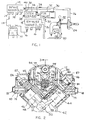
- Fig. 2 is a sectional view of a V- type engine embodying the invention, taken on line 2-2 in Fig. 3
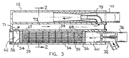
- Fig. 3 is a longitudinal sectional view taken along line 3-3 of Figure 2 showing an intake manifold employed in the Fig. 2 engine.
-
- Referring to Fig. 1, there is schematically shown a diesel engine equipped with a turbocharger and an exhaust gas recirculation system. The engine comprises a plurality of engine cylinders 10 supplied with combustion air from an
air intake manifold 12 andair intake passages 14. Exhaust gases are directed throughexhaust passages 16 to anexhaust manifold 18. - At least some of the exhaust gas travels through
passage 20 to aturbocharger turbine 22. The turbine impeller is driven by the fast-flowing gases to drive the impeller ofcompressor 24. Incoming air pressure inair line 26 is thereby boosted to increase the air flow intointake manifold 12. - A waste
gate relief valve 28 is provided to limit the amount of pressure boost inair line 26. Thewaste gate 28, when open, dumps some (or all) of the exhaust gas flowing throughpassage 20 bypassingturbine 22, thereby reducing the turbine impeller speed and the pressure boost provided bycompressor 24. - Some of the exhaust gas flowing out of
exhaust manifold 18 is recirculated back to theintake manifold 12 via agas recirculation passage 30. The recirculation gas passes through an exhaustgas recirculation valve 32 andintercooler 34. Anelectronic actuator 36, responsive to engine load and speed, and other engine variables, controlsgas recirculation valve 32. Theintercooler 34 can be a tube-shell heat exchanger, wherein the hot exhaust gases flow through the tubes and coolant flows through the shell around the tubes. The coolant can be liquid engine coolant flowing into/ out of the heat exchanger throughtubes recirculaiton passage 30 connects withair line 26 via anon-restrictive connection 40 that can include a venturi designed so that air flowing throughline 26 draws the recirculating gas into the air stream with at least some turbulence to allow mixing for a substantially uniform and homogeneous fuel/air mixture, and minimum pressure loss. - The present invention involves constructing the system of Fig. 1 so that
intercooler 34 andgas recirculation valve 32 are physically located withinintake manifold 12. The physical arrangement economizes on space, while at the same time simplifying some of the fluid connections that are required between the operating components. Figs. 2 and 3 illustrate one way in which the invention can be practiced. - Fig. 2 shows a turbocharged V configuration
internal combustion engine 42 having first and second banks ofcylinders cylinder axes 48 in the respective banks intersect at apoint 50. The cylinder axes are acutely angled to each other so that acentral space 52 is formed above theaxes intersection point 50. The engineair intake manifold 12 is located incentral space 52. - Manifold 12 comprises an elongated
cylindrical chamber 54 that accommodates a heatexchange tube bundle 34.Tube bundle 34 cooperates with the wall ofchamber 54 to form an intercooler for the recirculating exhaust gas. Those skilled in the art will understand that a similar strategy may be used for an air-to-water charge air cooler on engines which do not use Engine Gas Recirculation (EGR). For purposes of coordinating Figs. 2 and 3 with Fig. 1.numeral 34 is applied to the tube bundle in Fig. 2 and 3. - As shown in Fig. 3,
tube bundle 34 comprisesheaders chamber 54 surface, andplural baffles 59 spaced along the heat exchange tubes for baffling the ,flow of coolant around the tubes. Exhaust gas flows from aninlet chamber 60 through the heat exchange tubes to anexit chamber 62. - Referring to Fig. 2, two
engine coolant passages chamber 54 for circulating liquid coolant around the heat exchange tubes. Each coolant passage can be provided with a tubular end fitting at the right (rear) end of the manifold for connecting the respective passage to suitable coolant hoses.Coolant passages chamber 54 viaholes chamber 54 wall. - Liquid coolant flow through the intercooler is generally countercurrent to the gas flow. Liquid supplied to
passage 64 flows throughhole 67 into the space surrounding the tubes. Liquid flows fromchamber 54 throughhole 69 intopassage 66. -
Tube bundle 34 is mounted so thatheader 56 is secured to thechamber 54 wall, whileheader 58 is slideable on thechamber 54 surface (for thermal expansion stress relief).Header 58 has one or more "O" ring peripheral seals to prevent coolant leakage. - A suitable exhaust gas
recirculation valve cartridge 32 is mounted in the rear (right) end ofchamber 54 for modulating the flow of exhaust gas intoinlet space 60. The use of a cartridge eliminates the need for a separate valve housing, while at the same time reducing overall space requirements. - The cooled exhaust gas flows out of
exit space 62 though atransverse hole 71 into anelongated gas passage 73 extending abovechamber 54.Passage 73 communicates with asuction tube 75 that is carried by aventuri tube 77 extending into the right (rear) end of the manifold housing. The exposed end oftube 77 connects to the aforementioned air line 26 (Fig. 1), whereby the incoming air flows acrosssuction tube 75 to draw recirculating exhaust gas into the air flowing thoughmanifold 12 to the engine cylinders. - Venturi tube / / may be a cartridge formed separately from the manifold so as to serve as a connector for
air line 26 and also as a mechanism for assimilating the recirculation exhaust gas into the incoming air stream,with optimal turbulence for producing the proper air/fuel gas mixture. - Each bank of
cylinders cylinder head 79 havingair intake passage 81 andgas exhaust passages 83 communicating with the various cylinders, as shown in Fig. 2. Each cylinder head has a flatupper surface 80 adapted to mate with a flat mounting face onintake manifold 12, whereby the manifold is jointly supported by the two cylinder heads. Air openings in the mounting faces of the manifold align with theair intake passages 81 in the respective cylinder heads, whereby combustion air is admitted to intake valves in the cylinder heads. -
Manifold 12 is bolted tocylinder heads 79 by two individual sets of bolts located around the edge area of each cylinder head. Hollowtubular bosses 84 can be formed at spaced points along the manifold to accommodate some of the mounting bolts. Themanifold side walls 85 can be provided with suitable holes to accommodate other mounting bolts. Suitable gaskets are provided on theupper surfaces 80 of the cylinder heads. -
Upper surfaces 80 in the cylinder heads are located in a common horizontal plane, such that all of the mounting bolts forintake manifold 12 can be oriented vertically. The bolts expand or contract in unison to accommodate thermal expansion of the manifold, without generating undesired stresses in the manifold walls. - Each bank of
cylinders conventional rocker arms 86 for operating the intake and exhaust valves in the cylinder heads 79.Manifold 12 has twoside extensions 87 that form covers for the rocker arms. This feature eliminates the need for separate covers for the rocker arms. - A principal feature of the invention is the integration of the
intercooler 34 and exhaustgas recirculation valve 32 into the intake manifold.Internal chamber 54 within the intake manifold forms the housing for the intercooler.Gas recirculation valve 32 andventuri 77 are cartridge structures that can fit within the manifold to obviate the need for separate housings or mounting devices. The invention provides a structural simplification of the gas recirculation sub-system used in high performance, low emission, V configuration diesel engines. An incidental benefit is space economization in the engine compartment. Because the engine cooling system is linked to the manifold cooling passages, the cooling system thermostat may be integrated into the manifold. This construction eliminates the need for a separate thermostat housing for an engine system cost reduction. Heat from the intercooler may be used to supplement vehicle cabin heating and to assist engine warm-up for emissions control. - It will be appreciated that the illustrated structural arrangement is representative of the invention, and that the manifold-cooler assembly can be constructed in various ways while still practicing the invention.
Claims (15)
- A turbocharged V configuration internal combustion engine having first and second banks of cylinders arranged so that the cylinder axes in the respective banks intersect at an acute angle, whereby a central space is formed above the cylinder axes intersection point: an intake manifold located in said central space: and an intercooler located within said intake manifold.
- The engine of claim 1, wherein said intercooler comprises a heat exchanger having a tube bundle extending parallel to said cylinder axes intersection point.
- The engine of claim 1, wherein said intercooler comprises parallel heat exchange tubes arranged so that each tube is parallel to said cylinder axes intersection point.
- The engine of claim 1, and further comprising a turbocharger that includes a turbine driven by the exhaust gases from said cylinders and a compressor driven by said turbine, an exhaust manifold for delivering exhaust gases from said cylinders to said turbine, and a gas recirculation passage means for bypassing some of the exhaust manifold gas away from the turbine into said intercooler.
- The engine of claim 4, wherein said gas recirculation passage means comprises an exhaust gas recirculation valve located on said intake manifold.
- The engine of claim 5, wherein said exhaust gas recirculation valve comprises a valve cartridge partially embedded within said intake manifold.
- The engine of claim 5, and further comprising an air inlet means on said intake manifold communicating with said turbine; and a gas admission passage means, connecting said intercooler to said air inlet means whereby recirculation gas is assimilated into the air stream flowing through said air inlet means.
- The engine of claim 7, wherein said air inlet means comprises a venturi constructed to draw recirculation gas into the flowing air stream.
- The engine of claim 8, wherein said venturi comprises a venturi cartridge partially embedded within said intake manifold.
- The engine of claim 1, and future comprising a cylinder head overlying each bank of cylinders; said cylinder heads having upper flat surfaces located in a common plane; said intake manifold having flat lower mounting faces mated to the upper flat surfaces on said cylinder heads.
- The engine of claim 10, and further comprising a set of valve- actuation rocker arms located above each cylinder head; said intake manifold having said extensions that form covers for said rocker arms.
- The engine of claim 10, wherein each cylinder head has a set of air intake passages extending from its upper flat surface to the associated cylinders; said lower mounting faces on said air intake manifold having air admission openings aligned with said air intake passages.
- The engine of claim 1, further including a thermostat housing integrated into the manifold.
- The engine of claim 1, wherein heat from the intercooler is used to assist engine warm up for improved emission control.
- The engine of claim 14, wherein engine is mounted into a vehicle having a cabin, and the heat from the intercooler is used to supplement vehicle cabin heating.
Applications Claiming Priority (2)
| Application Number | Priority Date | Filing Date | Title |
|---|---|---|---|
| US215360 | 1994-03-21 | ||
| US09/215,360 US6116026A (en) | 1998-12-18 | 1998-12-18 | Engine air intake manifold having built-in intercooler |
Publications (2)
| Publication Number | Publication Date |
|---|---|
| EP1010889A2 true EP1010889A2 (en) | 2000-06-21 |
| EP1010889A3 EP1010889A3 (en) | 2000-11-29 |
Family
ID=22802680
Family Applications (1)
| Application Number | Title | Priority Date | Filing Date |
|---|---|---|---|
| EP99124574A Withdrawn EP1010889A3 (en) | 1998-12-18 | 1999-12-09 | Engine air intake manifold having built-in intercooler |
Country Status (7)
| Country | Link |
|---|---|
| US (1) | US6116026A (en) |
| EP (1) | EP1010889A3 (en) |
| JP (1) | JP2000186639A (en) |
| KR (1) | KR20000047594A (en) |
| AU (1) | AU756183B2 (en) |
| BR (1) | BR9905693A (en) |
| CA (1) | CA2283001A1 (en) |
Cited By (19)
| Publication number | Priority date | Publication date | Assignee | Title |
|---|---|---|---|---|
| EP1059435A3 (en) * | 1999-06-11 | 2001-06-20 | Pierburg Aktiengesellschaft | Arrangement of intake air conduits for a combustion engine |
| EP1069301A3 (en) * | 1999-07-13 | 2001-12-12 | Detroit Diesel Corporation | Internal combustion engine with wedge-shaped cylinder head and integral intake manifold |
| EP1479902A1 (en) * | 2003-05-14 | 2004-11-24 | Pierburg GmbH | Air intake system for internal combustion engine |
| DE102004049027A1 (en) * | 2004-10-08 | 2006-04-20 | Audi Ag | Internal combustion engine with charging module for motor vehicle has charger with two flange plates extending sideways from charger housing |
| EP1233170A3 (en) * | 2001-02-20 | 2006-05-03 | Nissan Motor Co., Ltd. | Recirculated exhaust gas cooling device for internal combustion engine |
| EP1375896A3 (en) * | 2002-06-25 | 2007-01-17 | Pierburg GmbH | Air intake system |
| FR2890699A1 (en) * | 2005-09-12 | 2007-03-16 | Valeo Systemes Thermiques | HEAT EXCHANGE MODULE FOR CONTROLLING THE GAS TEMPERATURE ADMITTED IN A VEHICLE ENGINE OF A VEHICLE WITH V-CYLINDER BENCHES |
| FR2906574A1 (en) * | 2006-09-29 | 2008-04-04 | Peugeot Citroen Automobiles Sa | Exhaust gas external recirculation providing device for gasoline direct injection or spark ignition type internal combustion engine, has duct traversing cylinder head while being surrounded by circuit to cool exhaust gas circulating in duct |
| FR2908832A1 (en) * | 2006-11-20 | 2008-05-23 | Valeo Systemes Thermiques | CARTER FOR HEAT EXCHANGER |
| EP1957783A1 (en) * | 2005-11-29 | 2008-08-20 | Volvo Lastvagnar AB | Exhaust gas recirculation mixer for a turbo-charged internal combustion engine |
| WO2008101978A1 (en) * | 2007-02-23 | 2008-08-28 | Mahle International Gmbh | Make-up gas module for a make-up gas installation |
| WO2011061311A1 (en) * | 2009-11-20 | 2011-05-26 | Behr Gmbh & Co. Kg | Intake pipe for an internal combustion engine |
| GB2487591A (en) * | 2011-01-28 | 2012-08-01 | Gm Global Tech Operations Inc | An EGR cooler located in an air intake manifold |
| EP2711533A1 (en) * | 2012-09-25 | 2014-03-26 | Bayerische Motoren Werke Aktiengesellschaft | Combustion engine |
| DE102013215347A1 (en) | 2012-09-21 | 2014-05-15 | Ford Global Technologies, Llc | Method for discharging liquid from an intake tract of a turbocharger arrangement and turbocharger arrangement for carrying out such a method |
| WO2014173492A1 (en) * | 2013-04-27 | 2014-10-30 | Deutz Aktiengesellschaft | Combustion engine |
| WO2018053459A1 (en) * | 2016-09-19 | 2018-03-22 | Cummins Inc. | Cast-in-head egr crossover tube with integral venturi tube for flow measurements |
| DE102007054955B4 (en) | 2007-11-17 | 2019-02-14 | Deutz Ag | Multi-cylinder internal combustion engine with V-shaped rows of cylinders and an exhaust gas recirculation cooler |
| EP4242438A1 (en) * | 2022-03-10 | 2023-09-13 | Yanmar Holdings Co., Ltd. | Engine |
Families Citing this family (48)
| Publication number | Priority date | Publication date | Assignee | Title |
|---|---|---|---|---|
| US6354084B1 (en) * | 1999-08-20 | 2002-03-12 | Cummins Engine Company, Inc. | Exhaust gas recirculation system for a turbocharged internal combustion engine |
| JP4323680B2 (en) * | 1999-09-30 | 2009-09-02 | 株式会社小松製作所 | Exhaust gas recirculation control device for internal combustion engine |
| ATE363022T1 (en) | 1999-12-14 | 2007-06-15 | Cooper Standard Automotive Inc | INTEGRATED EXHAUST GAS RECIRCULATION VALVE AND COOLER |
| DE10011954A1 (en) * | 2000-03-11 | 2001-09-13 | Modine Mfg Co | Exhaust gas heat exchanger in an exhaust gas recirculation arrangement |
| SE521262C2 (en) * | 2000-06-28 | 2003-10-14 | Volvo Lastvagnar Ab | Combustion engine with exhaust gas recirculation |
| US6604515B2 (en) | 2001-06-20 | 2003-08-12 | General Electric Company | Temperature control for turbocharged engine |
| US6601387B2 (en) | 2001-12-05 | 2003-08-05 | Detroit Diesel Corporation | System and method for determination of EGR flow rate |
| KR100476192B1 (en) * | 2001-12-06 | 2005-03-16 | 현대자동차주식회사 | Exhaust gas recirculation device of diesel engine |
| US6681171B2 (en) | 2001-12-18 | 2004-01-20 | Detroit Diesel Corporation | Condensation control for internal combustion engines using EGR |
| US6439212B1 (en) | 2001-12-19 | 2002-08-27 | Caterpillar Inc. | Bypass venturi assembly and elbow with turning vane for an exhaust gas recirculation system |
| US6659092B2 (en) | 2001-12-20 | 2003-12-09 | Caterpillar Inc | Bypass assembly with annular bypass venturi for an exhaust gas recirculation system |
| US6640542B2 (en) | 2001-12-20 | 2003-11-04 | Caterpillar Inc | Bypass venturi assembly with single shaft actuator for an exhaust gas recirculation system |
| DE10218521A1 (en) * | 2002-04-25 | 2003-11-06 | Behr Gmbh & Co | Exhaust gas heat exchanger, especially for motor vehicles |
| US6786210B2 (en) | 2002-06-21 | 2004-09-07 | Detroit Diesel Corporation | Working fluid circuit for a turbocharged engine having exhaust gas recirculation |
| US7011080B2 (en) * | 2002-06-21 | 2006-03-14 | Detroit Diesel Corporation | Working fluid circuit for a turbocharged engine having exhaust gas recirculation |
| US6742335B2 (en) | 2002-07-11 | 2004-06-01 | Clean Air Power, Inc. | EGR control system and method for an internal combustion engine |
| DE102004032777A1 (en) * | 2003-07-07 | 2005-07-14 | Behr Gmbh & Co. Kg | Arrangement for feeding gas mixture to engine cylinder induction ports has device(s) for adjusting gas mixture material composition/physical property according to engine management requirements |
| WO2005068101A1 (en) * | 2004-01-05 | 2005-07-28 | Cooper-Standard Automotive Inc. | Indented tube for a heat exchanger |
| FR2875540B1 (en) * | 2004-09-20 | 2007-03-16 | Mark Iv Systemes Moteurs Sa | MULTIFUNCTIONAL MODULE, MOTOR VEHICLE COMPRISING SUCH A MODULE AND METHOD OF MANUFACTURING SUCH A MODULE |
| US7287494B2 (en) | 2004-11-10 | 2007-10-30 | Buck Supply Co., Inc. | Multicylinder internal combustion engine with individual cylinder assemblies and modular cylinder carrier |
| US7287493B2 (en) | 2004-11-10 | 2007-10-30 | Buck Supply Co., Inc. | Internal combustion engine with hybrid cooling system |
| US7254948B2 (en) * | 2005-02-21 | 2007-08-14 | Cummins Inc. | Boost wastegate device for EGR assist |
| WO2006099263A2 (en) * | 2005-03-14 | 2006-09-21 | Api Heat Transfer Inc. | Heat insulator for an intake manifold of an air-cooled charge air cooler |
| KR100724801B1 (en) * | 2005-12-22 | 2007-06-04 | 한국항공우주연구원 | Test apparatus of intake flow in gas turbine engine |
| FR2920706B1 (en) * | 2007-09-12 | 2010-01-22 | Mark Iv Systemes Moteurs Sa | MULTIFUNCTIONAL MODULE FOR INTERNAL COMBUSTION ENGINE |
| US8316814B2 (en) | 2009-06-29 | 2012-11-27 | Buck Kenneth M | Toploading internal combustion engine |
| DE102009050258B3 (en) * | 2009-10-21 | 2010-11-18 | Mann + Hummel Gmbh | Intake manifold for internal combustion engine, particularly for motor vehicle, has coolant intercooler arranged at opposite end of cooling fluid boxes |
| US20110146632A1 (en) * | 2009-12-18 | 2011-06-23 | George Alfred Legg | System and Method for Improving Combustion Quality in Diesel Engine |
| JP2012097675A (en) * | 2010-11-02 | 2012-05-24 | Aisin Seiki Co Ltd | Intake system of internal combustion engine |
| DE102011002552A1 (en) * | 2011-01-12 | 2012-07-12 | Ford Global Technologies, Llc | Charged internal combustion engine and method for operating such an internal combustion engine |
| DE102011051691A1 (en) * | 2011-07-08 | 2013-01-10 | Dr. Ing. H.C. F. Porsche Aktiengesellschaft | Noise transmission system |
| DE102011051689A1 (en) | 2011-07-08 | 2013-01-10 | Dr. Ing. H.C. F. Porsche Ag | Noise transmission system |
| DE102013200255A1 (en) | 2012-02-21 | 2013-08-22 | Ford Global Technologies, Llc | Internal combustion engine with fresh air cooling |
| GB2501304B (en) | 2012-04-19 | 2019-01-16 | Ford Global Tech Llc | Apparatus and method for engine warm up |
| US9422877B2 (en) | 2013-10-11 | 2016-08-23 | General Electric Company | System and method for control of exhaust gas recirculation (EGR) utilizing process temperatures |
| KR101534725B1 (en) * | 2013-12-06 | 2015-07-07 | 현대자동차 주식회사 | Engine system having turbo charger |
| KR101490963B1 (en) * | 2013-12-11 | 2015-02-06 | 현대자동차 주식회사 | Engine system having turbo charger |
| KR20150075421A (en) | 2013-12-17 | 2015-07-06 | 현대자동차주식회사 | Engine system having turbo charger |
| KR101575254B1 (en) | 2014-05-20 | 2015-12-07 | 현대자동차 주식회사 | Cooling and thermoelectric power generating system for vehicle |
| US9765734B2 (en) * | 2014-12-23 | 2017-09-19 | Ford Global Technologies, Llc | Active airpath bypass system |
| JP6459498B2 (en) * | 2014-12-24 | 2019-01-30 | 三菱自動車工業株式会社 | Engine intake structure |
| US10288012B2 (en) | 2016-01-28 | 2019-05-14 | Ford Global Technologies, Llc | Arrangement for introducing water into the intake manifold of an internal combustion engine and control device |
| KR101826564B1 (en) | 2016-03-16 | 2018-02-07 | 현대자동차 주식회사 | Engine having integrated heat exchanger |
| DE202016104441U1 (en) | 2016-07-25 | 2016-08-22 | Ford Global Technologies, Llc | Internal combustion engine with intercooling by air conditioning system |
| DE102016213588B4 (en) | 2016-07-25 | 2021-06-10 | Ford Global Technologies, Llc | Internal combustion engine with charge air cooling through an air conditioning system |
| DE102016213590A1 (en) | 2016-07-25 | 2018-01-25 | Ford Global Technologies, Llc | Internal combustion engine with intercooling by air conditioning system |
| US10156215B2 (en) * | 2016-08-16 | 2018-12-18 | GM Global Technology Operations LLC | Manifold assembly |
| US11280301B2 (en) * | 2020-01-20 | 2022-03-22 | Mazda Motor Corporation | Intake device of engine |
Citations (5)
| Publication number | Priority date | Publication date | Assignee | Title |
|---|---|---|---|---|
| US3937196A (en) * | 1975-02-05 | 1976-02-10 | Ford Motor Company | Intake manifold for an internal combustion engine having an internally contained exhaust gas recirculation cooler |
| US4258687A (en) * | 1979-10-09 | 1981-03-31 | Ford Motor Company | Engine with integral mounted EGR cooler |
| DE19821792A1 (en) * | 1997-05-28 | 1998-12-03 | Avl List Gmbh | IC engine with turbocharger |
| DE19736500A1 (en) * | 1997-08-22 | 1998-12-24 | Daimler Benz Ag | Arrangement for ancillary equipment of twin turbo-charged V-eight IC engine |
| DE19853455A1 (en) * | 1997-11-28 | 1999-06-02 | Avl List Gmbh | Cooling system for supercharged motor |
Family Cites Families (5)
| Publication number | Priority date | Publication date | Assignee | Title |
|---|---|---|---|---|
| US2551307A (en) * | 1944-10-14 | 1951-05-01 | Frank B Yingling | Turbocharged two-cycle engine with liquid cooled exhaust ducts |
| US3881455A (en) * | 1973-10-31 | 1975-05-06 | Allis Chalmers | Aftercooler for internal combustion engine |
| FR2271394B1 (en) * | 1974-05-15 | 1978-03-24 | France Etat | |
| US4028892A (en) * | 1974-09-09 | 1977-06-14 | General Motors Corporation | Turbocharged two-cycle engine with positive blower and internally mounted aftercooler |
| US5163613A (en) * | 1991-06-03 | 1992-11-17 | Ragan Alton R | Thermostat bypass |
-
1998
- 1998-12-18 US US09/215,360 patent/US6116026A/en not_active Expired - Fee Related
-
1999
- 1999-08-24 AU AU44660/99A patent/AU756183B2/en not_active Ceased
- 1999-09-22 CA CA002283001A patent/CA2283001A1/en not_active Abandoned
- 1999-11-05 KR KR1019990048821A patent/KR20000047594A/en not_active Application Discontinuation
- 1999-12-02 BR BR9905693-3A patent/BR9905693A/en unknown
- 1999-12-08 JP JP11348541A patent/JP2000186639A/en not_active Withdrawn
- 1999-12-09 EP EP99124574A patent/EP1010889A3/en not_active Withdrawn
Patent Citations (5)
| Publication number | Priority date | Publication date | Assignee | Title |
|---|---|---|---|---|
| US3937196A (en) * | 1975-02-05 | 1976-02-10 | Ford Motor Company | Intake manifold for an internal combustion engine having an internally contained exhaust gas recirculation cooler |
| US4258687A (en) * | 1979-10-09 | 1981-03-31 | Ford Motor Company | Engine with integral mounted EGR cooler |
| DE19821792A1 (en) * | 1997-05-28 | 1998-12-03 | Avl List Gmbh | IC engine with turbocharger |
| DE19736500A1 (en) * | 1997-08-22 | 1998-12-24 | Daimler Benz Ag | Arrangement for ancillary equipment of twin turbo-charged V-eight IC engine |
| DE19853455A1 (en) * | 1997-11-28 | 1999-06-02 | Avl List Gmbh | Cooling system for supercharged motor |
Cited By (31)
| Publication number | Priority date | Publication date | Assignee | Title |
|---|---|---|---|---|
| EP1059435A3 (en) * | 1999-06-11 | 2001-06-20 | Pierburg Aktiengesellschaft | Arrangement of intake air conduits for a combustion engine |
| EP1069301A3 (en) * | 1999-07-13 | 2001-12-12 | Detroit Diesel Corporation | Internal combustion engine with wedge-shaped cylinder head and integral intake manifold |
| EP1233170A3 (en) * | 2001-02-20 | 2006-05-03 | Nissan Motor Co., Ltd. | Recirculated exhaust gas cooling device for internal combustion engine |
| EP1375896A3 (en) * | 2002-06-25 | 2007-01-17 | Pierburg GmbH | Air intake system |
| EP1479902A1 (en) * | 2003-05-14 | 2004-11-24 | Pierburg GmbH | Air intake system for internal combustion engine |
| DE102004049027A1 (en) * | 2004-10-08 | 2006-04-20 | Audi Ag | Internal combustion engine with charging module for motor vehicle has charger with two flange plates extending sideways from charger housing |
| DE102004049027B4 (en) * | 2004-10-08 | 2010-05-27 | Audi Ag | Internal combustion engine and supercharger module for an internal combustion engine |
| WO2007031637A1 (en) * | 2005-09-12 | 2007-03-22 | Valeo Systemes Thermiques | Heat exchange module for controlling temperature of intake gases in a two-bank internal combustion engine for a motor vehicle |
| FR2890699A1 (en) * | 2005-09-12 | 2007-03-16 | Valeo Systemes Thermiques | HEAT EXCHANGE MODULE FOR CONTROLLING THE GAS TEMPERATURE ADMITTED IN A VEHICLE ENGINE OF A VEHICLE WITH V-CYLINDER BENCHES |
| EP1957783A1 (en) * | 2005-11-29 | 2008-08-20 | Volvo Lastvagnar AB | Exhaust gas recirculation mixer for a turbo-charged internal combustion engine |
| EP1957783A4 (en) * | 2005-11-29 | 2011-10-12 | Volvo Lastvagnar Ab | Exhaust gas recirculation mixer for a turbo-charged internal combustion engine |
| FR2906574A1 (en) * | 2006-09-29 | 2008-04-04 | Peugeot Citroen Automobiles Sa | Exhaust gas external recirculation providing device for gasoline direct injection or spark ignition type internal combustion engine, has duct traversing cylinder head while being surrounded by circuit to cool exhaust gas circulating in duct |
| EP1908951A1 (en) | 2006-09-29 | 2008-04-09 | Peugeot Citroën Automobiles S.A. | Device for recirculating exhaust gas from an internal combustion engine and internal combustion engine equipped with such a device |
| FR2908832A1 (en) * | 2006-11-20 | 2008-05-23 | Valeo Systemes Thermiques | CARTER FOR HEAT EXCHANGER |
| WO2008061850A1 (en) * | 2006-11-20 | 2008-05-29 | Valeo Systemes Thermiques | Heat exchange device and gas-intake device including such device |
| WO2008101978A1 (en) * | 2007-02-23 | 2008-08-28 | Mahle International Gmbh | Make-up gas module for a make-up gas installation |
| DE102007054955B4 (en) | 2007-11-17 | 2019-02-14 | Deutz Ag | Multi-cylinder internal combustion engine with V-shaped rows of cylinders and an exhaust gas recirculation cooler |
| CN102667094A (en) * | 2009-11-20 | 2012-09-12 | 贝洱两合公司 | Intake pipe for an internal combustion engine |
| WO2011061311A1 (en) * | 2009-11-20 | 2011-05-26 | Behr Gmbh & Co. Kg | Intake pipe for an internal combustion engine |
| CN102667094B (en) * | 2009-11-20 | 2016-01-20 | 马勒国际公司 | For the sucking pipe of internal-combustion engine |
| US9605586B2 (en) | 2009-11-20 | 2017-03-28 | Mahle International Gmbh | Intake pipe for an internal combustion engine |
| GB2487591A (en) * | 2011-01-28 | 2012-08-01 | Gm Global Tech Operations Inc | An EGR cooler located in an air intake manifold |
| GB2487591B (en) * | 2011-01-28 | 2016-07-20 | Gm Global Tech Operations Llc | Internal Combustion Engine Having a Cooler Located in an Intake Manifold |
| DE102013215347A1 (en) | 2012-09-21 | 2014-05-15 | Ford Global Technologies, Llc | Method for discharging liquid from an intake tract of a turbocharger arrangement and turbocharger arrangement for carrying out such a method |
| DE102013215347B4 (en) * | 2012-09-21 | 2015-12-10 | Ford Global Technologies, Llc | Method for discharging liquid from an intake tract of a turbocharger arrangement and turbocharger arrangement for carrying out such a method |
| US9334790B2 (en) | 2012-09-21 | 2016-05-10 | Ford Global Technologies, Llc | System and method for discharging liquid out of an intake tract of a turbocharger arrangement |
| EP2711533A1 (en) * | 2012-09-25 | 2014-03-26 | Bayerische Motoren Werke Aktiengesellschaft | Combustion engine |
| WO2014173492A1 (en) * | 2013-04-27 | 2014-10-30 | Deutz Aktiengesellschaft | Combustion engine |
| WO2018053459A1 (en) * | 2016-09-19 | 2018-03-22 | Cummins Inc. | Cast-in-head egr crossover tube with integral venturi tube for flow measurements |
| US10724452B2 (en) | 2016-09-19 | 2020-07-28 | Cummins Inc. | Cast-in-head EGR crossover tube with integral venturi tube for flow measurements |
| EP4242438A1 (en) * | 2022-03-10 | 2023-09-13 | Yanmar Holdings Co., Ltd. | Engine |
Also Published As
| Publication number | Publication date |
|---|---|
| BR9905693A (en) | 2000-09-05 |
| KR20000047594A (en) | 2000-07-25 |
| US6116026A (en) | 2000-09-12 |
| AU4466099A (en) | 2000-06-22 |
| CA2283001A1 (en) | 2000-06-18 |
| JP2000186639A (en) | 2000-07-04 |
| AU756183B2 (en) | 2003-01-09 |
| EP1010889A3 (en) | 2000-11-29 |
Similar Documents
| Publication | Publication Date | Title |
|---|---|---|
| US6116026A (en) | Engine air intake manifold having built-in intercooler | |
| US7625257B1 (en) | Exhaust gas recirculation cooling system for an engine of an outboard motor | |
| JP3544269B2 (en) | EGR device for engine | |
| JP4629264B2 (en) | An internal combustion engine, in particular an automobile, with an exhaust gas recirculation system | |
| EP0763655B1 (en) | Structure for supporting EGR valve in engine | |
| US7942138B1 (en) | Outboard motor with exhaust gas recirculation cooling | |
| US20090260605A1 (en) | Staged arrangement of egr coolers to optimize performance | |
| US7584748B2 (en) | Exhaust gas recirculation system for an internal combustion engine | |
| US7448368B2 (en) | Exhaust gas recirculation system for an internal combustion engine | |
| JP2001248448A (en) | Intake air cooling device of internal combustion engine | |
| CN113494394B (en) | EGR system of engine | |
| JP3240795B2 (en) | EGR gas cooling structure | |
| EP1794424A1 (en) | Engine with charge air-cooling system with water fumigation | |
| JP3392513B2 (en) | V-type engine exhaust recirculation system | |
| JPH10220305A (en) | Egr device with intercooler | |
| JP2001254648A (en) | Exhaust gas recirculation system of internal combustion engine | |
| JPS61279733A (en) | Multicylinder turbosupercharged engine | |
| JP2517063Y2 (en) | Intake manifold cooling device for V-type internal combustion engine in automobile | |
| MXPA99011775A (en) | Engine air intake manifold having built-in intercooler | |
| JP4027547B2 (en) | EGR device | |
| US20170234208A1 (en) | Multiple Intake Air Coolers Arranged in Parallel | |
| JP3502356B2 (en) | Ventilation piping structure for water cooling system for vehicles | |
| JP2592608Y2 (en) | Cooling passage structure for multiple turbocharged engines | |
| JPH0614072Y2 (en) | Fuel piping structure in V-type multi-cylinder engine | |
| JPS5820924A (en) | Intake device for engine with supercharger |
Legal Events
| Date | Code | Title | Description |
|---|---|---|---|
| PUAI | Public reference made under article 153(3) epc to a published international application that has entered the european phase |
Free format text: ORIGINAL CODE: 0009012 |
|
| AK | Designated contracting states |
Kind code of ref document: A2 Designated state(s): DE FR GB IT |
|
| AX | Request for extension of the european patent |
Free format text: AL;LT;LV;MK;RO;SI |
|
| PUAL | Search report despatched |
Free format text: ORIGINAL CODE: 0009013 |
|
| AK | Designated contracting states |
Kind code of ref document: A3 Designated state(s): AT BE CH CY DE DK ES FI FR GB GR IE IT LI LU MC NL PT SE |
|
| AX | Request for extension of the european patent |
Free format text: AL;LT;LV;MK;RO;SI |
|
| 17P | Request for examination filed |
Effective date: 20010105 |
|
| AKX | Designation fees paid |
Free format text: DE FR GB IT |
|
| STAA | Information on the status of an ep patent application or granted ep patent |
Free format text: STATUS: THE APPLICATION HAS BEEN WITHDRAWN |
|
| 18W | Application withdrawn |
Withdrawal date: 20021002 |