EP1010877A2 - Stroke transmission - Google Patents
Stroke transmission Download PDFInfo
- Publication number
- EP1010877A2 EP1010877A2 EP99125229A EP99125229A EP1010877A2 EP 1010877 A2 EP1010877 A2 EP 1010877A2 EP 99125229 A EP99125229 A EP 99125229A EP 99125229 A EP99125229 A EP 99125229A EP 1010877 A2 EP1010877 A2 EP 1010877A2
- Authority
- EP
- European Patent Office
- Prior art keywords
- stroke
- lever
- drive element
- lifting
- lifting element
- Prior art date
- Legal status (The legal status is an assumption and is not a legal conclusion. Google has not performed a legal analysis and makes no representation as to the accuracy of the status listed.)
- Granted
Links
- 230000005540 biological transmission Effects 0.000 title claims description 29
- 230000000694 effects Effects 0.000 claims abstract description 12
- 208000006011 Stroke Diseases 0.000 claims description 142
- 238000000034 method Methods 0.000 claims description 13
- 239000000446 fuel Substances 0.000 claims description 5
- 230000007935 neutral effect Effects 0.000 claims description 5
- 239000000919 ceramic Substances 0.000 claims description 2
- 230000000284 resting effect Effects 0.000 abstract 1
- 108010014172 Factor V Proteins 0.000 description 31
- 230000001419 dependent effect Effects 0.000 description 3
- 238000006073 displacement reaction Methods 0.000 description 3
- 238000005516 engineering process Methods 0.000 description 3
- 238000002347 injection Methods 0.000 description 3
- 239000007924 injection Substances 0.000 description 3
- 238000004519 manufacturing process Methods 0.000 description 3
- 238000010276 construction Methods 0.000 description 2
- 230000002349 favourable effect Effects 0.000 description 2
- 239000012530 fluid Substances 0.000 description 2
- 239000000463 material Substances 0.000 description 2
- 206010015137 Eructation Diseases 0.000 description 1
- 206010067171 Regurgitation Diseases 0.000 description 1
- 208000027687 belching Diseases 0.000 description 1
- 238000005452 bending Methods 0.000 description 1
- 230000007423 decrease Effects 0.000 description 1
- 238000003780 insertion Methods 0.000 description 1
- 230000037431 insertion Effects 0.000 description 1
- 238000000926 separation method Methods 0.000 description 1
Images


Classifications
-
- F—MECHANICAL ENGINEERING; LIGHTING; HEATING; WEAPONS; BLASTING
- F02—COMBUSTION ENGINES; HOT-GAS OR COMBUSTION-PRODUCT ENGINE PLANTS
- F02B—INTERNAL-COMBUSTION PISTON ENGINES; COMBUSTION ENGINES IN GENERAL
- F02B75/00—Other engines
- F02B75/32—Engines characterised by connections between pistons and main shafts and not specific to preceding main groups
-
- F—MECHANICAL ENGINEERING; LIGHTING; HEATING; WEAPONS; BLASTING
- F02—COMBUSTION ENGINES; HOT-GAS OR COMBUSTION-PRODUCT ENGINE PLANTS
- F02M—SUPPLYING COMBUSTION ENGINES IN GENERAL WITH COMBUSTIBLE MIXTURES OR CONSTITUENTS THEREOF
- F02M51/00—Fuel-injection apparatus characterised by being operated electrically
- F02M51/06—Injectors peculiar thereto with means directly operating the valve needle
- F02M51/061—Injectors peculiar thereto with means directly operating the valve needle using electromagnetic operating means
-
- F—MECHANICAL ENGINEERING; LIGHTING; HEATING; WEAPONS; BLASTING
- F02—COMBUSTION ENGINES; HOT-GAS OR COMBUSTION-PRODUCT ENGINE PLANTS
- F02M—SUPPLYING COMBUSTION ENGINES IN GENERAL WITH COMBUSTIBLE MIXTURES OR CONSTITUENTS THEREOF
- F02M2200/00—Details of fuel-injection apparatus, not otherwise provided for
- F02M2200/21—Fuel-injection apparatus with piezoelectric or magnetostrictive elements
-
- Y—GENERAL TAGGING OF NEW TECHNOLOGICAL DEVELOPMENTS; GENERAL TAGGING OF CROSS-SECTIONAL TECHNOLOGIES SPANNING OVER SEVERAL SECTIONS OF THE IPC; TECHNICAL SUBJECTS COVERED BY FORMER USPC CROSS-REFERENCE ART COLLECTIONS [XRACs] AND DIGESTS
- Y10—TECHNICAL SUBJECTS COVERED BY FORMER USPC
- Y10T—TECHNICAL SUBJECTS COVERED BY FORMER US CLASSIFICATION
- Y10T74/00—Machine element or mechanism
- Y10T74/20—Control lever and linkage systems
- Y10T74/20558—Variable output force
- Y10T74/2057—Variable input leverage
Definitions
- the invention relates to an apparatus and a method for Stroke transmission between a drive element and a Lifting element.
- a hub transmission is often used in an area in a separation of a drive system into a drive element and a lifting element is advantageous, for example due to a simplified production, a material technology different versions or a stroke change.
- a stroke reduction corresponding to a stroke factor ⁇ ⁇ 1
- a stroke ratio occurs at a stroke factor ⁇ > 1, for example in the case of small-stroke actuators whose stroke is to be increased via a lifting element for the necessary application safety.
- the ratio of the area exposed to pressure of the drive element to the exposed surface of the Lift element directly determines the stroke factor.
- a problem with stroke transmission is that a combination of different types of stroke transmission is often required, e.g. B. a neutral stroke transmission at the beginning of an operation with the following stroke ratio, z. B. in a stroke transfer from a piezoelectric actuator to a nozzle needle for operating a servo-valve-controlled fuel injector.
- a high amount of force must be used to open a servo valve chamber precisely and initially. Immediately after the belching, the pressure in the valve chamber drops to a low value, so that a considerably lower force is sufficient for further opening.
- injection quantity, start of injection For the reproducibility of the opening behavior within narrow tolerances (injection quantity, start of injection), a wide opening of the valve chamber is required. Due to the small useful stroke of the piezo actuator, a stroke ratio is necessary.
- a sliding drive element one in the same direction displaceable lifting element and at least one Lever used.
- the lever is permanently on the drive element and can be placed on the lifting element and on a bearing.
- the primary stroke xp at which the lever actually rests on the lifting element and the bearing depends on the particular embodiment and on the primary stroke xp. However, if there is a simultaneous support of the lever on the lifting element, the drive element and the bearing, this results in a lever effect, so that the primary stroke xp can be transferred to the lifting element via the lever effect of the lever.
- the stroke transmission is designed such that the stroke factor ⁇ can be changed at least once by changing at least one contact point with a changing primary stroke xp.
- a contact point is understood to mean a pivot point, a lifting point or a force introduction point.
- a change in a contact point is understood to mean a change in a contact condition, that is to say both a production of a contact, e.g. B. by placing the lever, as well as changing the pivot point, lifting point or force application point.
- Such a mechanical stroke transmission has the advantage that compared to a hydraulic or mechanical-hydraulic Stroke transfer to the use of a fluid chamber can be dispensed with. This results in z. B. the advantage that the secondary stroke xs largely independent of the Actuation time is.
- a very flexible geometric configuration is also expediently of the individual components possible, so that the stroke factor ⁇ can be varied over a wide range. So he is dependent from the primary stroke xp, continuously or abruptly changeable.
- the stroke factor ⁇ can e.g. B. growing, constant, falling or can be combined in any combination.
- the lever For easy adjustment of the stroke factor ⁇ , it is advantageous if the lever always rests on a pivot point on the bearing.
- a lever effect of the levers can be transferred to the lifting element.
- the change of a contact point corresponds to the placement of the lever on the lifting element.
- a stroke factor ⁇ between 1 (e.g. initial Opening the servo valve with high force) to 10 (e.g. wide Regurgitation preferred).
- each lever rests on the drive element via an internal force introduction point.
- the stroke factor ⁇ can in turn be changed by changing the force application point.
- the stroke factor ⁇ can change at least in regions within a stroke interval ⁇ xp ⁇ , but it can also remain constant in regions.
- the (inner and outer) force introduction points are arranged at least in some areas continuously, ie spatially merging. It is thus possible to vary the stroke factor ⁇ continuously with a constant change in the primary stroke xp.
- the lever rests on an at least partially curved surface of the drive element, so that a continuous change in the stroke factor ⁇ can be set at least partially by means of the primary stroke xp.
- a primary stroke xp of 10 ⁇ m to 100 ⁇ m is executable. This is typically the case if that Drive element from a piezo actuator or a magneto or electrostrictive element is driven. Doing so Use of a ceramic multilayer piezo actuator in particular prefers.
- Figure 1 is a sectional side view Means for stroke transmission shown in the starting position, in which two different lifting factors during a lifting process ⁇ can be used.
- a lifting element 1 sits loosely on a drive element 3.
- Two one-sided levers 2 are shown, each of which at a force introduction point 7 on the drive element 3 lie on.
- Each lever 2 is also at a pivot point 5 of a bearing 4.
- the levers 2 are also on one Lift point 6 can be placed on the lifting element 1, in this embodiment by attaching it to a drive element 3 facing top surface 9.
- the lifting element 1 and the drive element 3 are designed such that they are geometrically similar in themselves either under any rotation about the axis of rotation I (completely rotationally symmetrical) or after a rotation through an angle of 360 ° / n (n-fold rotationally symmetrical) are transferable.
- n levers (n ⁇ + ) be uniformly distributed at an angular distance of 360 ° / n from one another
- the lifting element 1 is designed to be completely rotationally symmetrical and the drive element 3 has webs as force introduction points 7 at an angular distance of 360 ° / n.
- the drive element 3 can also be designed to be completely rotationally symmetrical, so that the force introduction points 7 lie on a ring of the drive element 3 about the axis of rotation I.
- the distance between lifting point 6 and pivot point 5 is called Load arm of length L1 + L2 and the distance between the force application point 7 and pivot point 5 is used as a force arm of length L1 designated.
- the primary Driving force Fp is via an actuator, e.g. B. one Piezo actuator, applied, the drive element 3 being a part of the actuator.
- the lifting element 1 by its secondary stroke xs shifted in the same direction, being a secondary Driving force Fs is forwardable.
- Figure 2 shows a sectional side view schematically a stroke transmitter according to Figure 1, in the starting position (Figure 2a), at the time of touchdown Lever 2 on the lifting element 1 (Figure 2b), and after insertion the leverage (Figure 2c).
- Figure 2a shows the image of the hub transmitter analogous to Figure 1 in the starting position.
- a drive means for displacing the drive element 3 can use all types of actuators or actuators become.
- a piezo actuator as a drive means.
- FIG. 2c shows the stroke transmitter with a primary stroke xp> xt.
- a stroke ratio ⁇ L2 / L1 , here: ⁇ > 1, is present.
- the lifting element 1 lifts off the drive element 3 and is displaced solely on the basis of the leverage effect.
- a distance between the drive element 3 and the lifting element 1 can be provided in addition to the distance h in the starting position.
- Figure 3b shows that until the switch point xt is reached the values of the stroke transmitter are those of the direct drive correspond and quickly after reaching the switching point xt drop to the values of the pure lever drive.
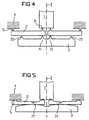
- Figure 4 shows a sectional side view Another embodiment of a stroke transmitter in the starting position.
- the at least two levers 2 lie on one inner force introduction point 71 on the drive element 3 on.
- the lifting element 1 rests on one Lift point 6 on the levers 2 and at a pivot point 5 on the Camp 4 on.
- the lever 2 becomes a mechanical one Non-positive connection between the drive element 3 and the lifting element 1 mediates.
- the drive element 3 is along the axis of rotation I shifted relative to the bearing 4. Because the length L1 of the power arm is equal to the effective length L1 + L2 of lever 2, lever 2 does not Leverage creates, but the primary stroke xp directly Transfer to the lifting element 1 without loss of stroke. At the same time are by the movement of the lifting element 3 relative to the Bear the levers 2 in the direction of the drive element 3 rotated, the inner force application point 71 as Pivotal effect.
- the length L1 of the force arm changes, which is now smaller than the length L1 + L2 of the load arm.
- FIG. 5 shows another embodiment in the starting position shown as a sectional view in side view.
- the surface can also be curved such that a neutral stroke transmission takes place when the drive element 3 is displaced.
- the surface can also be shaped such that the stroke factor ⁇ only changes continuously in sections, for example in that the surface is concave and convex in sections in the direction of the lifting element 1.
- the at least one lever 2 is also a curved, at least on one contact point 5,6,7,71, ..., 7n, 71 ', ..., 7n' has an overlying surface.
- lever bearings e.g. B. cutting edge bearings or roller and bending bearings and combinations thereof.
- An initial direct frictional connection between the drive element (3) and the lifting element (1) can also take place via cams passing laterally past the levers (2).
Abstract
Description
Die Erfindung betrifft eine Vorrichtung und ein Verfahren zur Hubübertragung zwischen einem Antriebselement und einem Hubelement.The invention relates to an apparatus and a method for Stroke transmission between a drive element and a Lifting element.
Eine Hubübertragung wird oft in einem Bereich eingesetzt, in dem eine Trennung eines Antriebssystems in ein Antriebselement und ein Hubelement vorteilhaft ist, beispielsweise aufgrund einer vereinfachten Herstellung, einer werkstofftechnisch unterschiedlichen Ausführung oder einer Hubänderung.A hub transmission is often used in an area in a separation of a drive system into a drive element and a lifting element is advantageous, for example due to a simplified production, a material technology different versions or a stroke change.
Bei der Hubübertragung stellt sich ein bestimmtes Verhältnis
zwischen dem Sekundärhub xs des Hubelementes und dem Primärhub
xp des Antriebselementes ein, ausgedrückt durch den Hubfaktor
Eine Hubuntersetzung, entsprechend einem Hubfaktor Π < 1,
wird beispielsweise in Systemen realisiert, bei denen ein
vergleichsweise großhubiger Motor ein Hubelement mit einem
kleinen Stellweg antreiben soll.
Eine neutrale Hubübertragung, entsprechend einem Hubfaktor Π
= 1, ist beispielsweise gewünscht, falls der Hub eines Stellantriebs
präzise über ein werkstofftechnisch unterschiedlich
ausgeführtes Hubelement weitergegeben werden soll.
Eine Hubübersetzung tritt bei einem Hubfaktor Π > 1 auf,
beispielsweise bei kleinhubigen Aktoren, deren Hub über ein
Hubelement zur notwendigen Anwendungssicherheit vergrößert
werden soll.During the stroke transmission, a certain relationship is established between the secondary stroke xs of the lifting element and the primary stroke xp of the drive element, expressed by the stroke factor
A stroke reduction, corresponding to a stroke factor Π <1, is implemented, for example, in systems in which a comparatively large-stroke motor is intended to drive a lifting element with a short travel range.
A neutral stroke transmission, corresponding to a stroke factor Π = 1, is desired, for example, if the stroke of an actuator is to be passed on precisely via a lifting element that is different in terms of material technology.
A stroke ratio occurs at a stroke factor Π> 1, for example in the case of small-stroke actuators whose stroke is to be increased via a lifting element for the necessary application safety.
Zur Hubübertragung, insbesondere bei der Hubübersetzung, ist aus DE 195 19 191 A1 und DE 43 06 072 C2 der Einsatz einer Hydraulikkammer zwischen dem Antriebselement und dem Hubelement bekannt, wobei das Verhältnis der druckausgesetzten Fläche des Antriebselementes zur druckausgesetzten Fläche des Hubelementes direkt den Hubfaktor bestimmt. For stroke transmission, in particular in the case of stroke translation from DE 195 19 191 A1 and DE 43 06 072 C2 the use of a Hydraulic chamber between the drive element and the lifting element known, the ratio of the area exposed to pressure of the drive element to the exposed surface of the Lift element directly determines the stroke factor.
Ein Problem bei der Hubübertragung besteht darin, daß oft
eine Kombination von verschiedenen Arten der Hubübertragung
benötigt wird, z. B. eine neutrale Hubübertragung am Anfang
eines Betätigungsvorgangs mit folgender Hubübersetzung, z. B.
bei einem Hubübertrag von einem piezoelektrischen Aktor auf
eine Düsennadel zum Betrieb eines servoventil-gesteuerten
Kraftstoff-Einspritzers.
Dabei muß zum anfänglichen, präzisen Öffnen einer Servoventilkammer
eine hohe Kraft aufgewendet werden. Unmittelbar
nach dem Aufstoßen fällt der Druck in der Ventilkammer auf
einen geringen Wert ab, so daß zum weiteren Öffnen eine wesentlich
geringere Kraft ausreicht. Zur Reproduzierbarkeit
des Öffnungsverhaltens innerhalb enger Toleranzen (Einspritzmenge,
Spritzbeginn) ist eine weite Öffnung der Ventilkammer
erforderlich. Aufgrund des geringen Nutzhubes des Piezoaktors
ist dazu eine Hubübersetzung notwendig.A problem with stroke transmission is that a combination of different types of stroke transmission is often required, e.g. B. a neutral stroke transmission at the beginning of an operation with the following stroke ratio, z. B. in a stroke transfer from a piezoelectric actuator to a nozzle needle for operating a servo-valve-controlled fuel injector.
A high amount of force must be used to open a servo valve chamber precisely and initially. Immediately after the belching, the pressure in the valve chamber drops to a low value, so that a considerably lower force is sufficient for further opening. For the reproducibility of the opening behavior within narrow tolerances (injection quantity, start of injection), a wide opening of the valve chamber is required. Due to the small useful stroke of the piezo actuator, a stroke ratio is necessary.
Eine Methode zur Hubübertragung mit vom Primärhub xp abhängigen Hubfaktor Π ist nicht bekannt.A method of stroke transmission with the xp dependent primary stroke Stroke factor Π is not known.
Es ist die Aufgabe der vorliegenden Erfindung, eine Möglichkeit zur Hubübertragung mit variablem Hubfaktor Π bereitzustellen.It is the object of the present invention, one way to provide stroke transmission with variable stroke factor Π.
Diese Aufgabe wird durch eine Vorrichtung gemäß der Merkmale
des Anspruchs 1 sowie mittels eines Verfahrens gemäß der
Merkmale der Ansprüche 13 und 14 gelöst. Vorteilhafte Ausgestaltungen
sind den nachgeordneten Ansprüchen entnehmbar.This object is achieved by a device according to the features
of
Dazu werden ein verschiebbares Antriebselement, ein in die gleiche Richtung verschiebbares Hubelement und mindestens ein Hebel verwendet.For this purpose, a sliding drive element, one in the same direction displaceable lifting element and at least one Lever used.
Falls nichts anderes ausgesagt, wird zum besseren Verständnis
unter ![]()
![]()
Der Hebel liegt dauernd auf dem Antriebselement auf und ist
auf dem Hubelement und auf einem Lager aufsetzbar. Bei welchem
Primärhub xp der Hebel tatsächlich auf dem Hubelement
und dem Lager aufliegt, hängt von der jeweiligen Ausführungsform
und vom Primärhub xp ab.
Falls aber eine gleichzeitige Auflage des Hebels auf dem Hubelement,
dem Antriebselement und dem Lager vorhanden ist, resultiert
daraus eine Hebelwirkung, so daß der Primärhub xp
über die Hebelwirkung des Hebels auf das Hubelement übertragbar
ist. Dabei ist der Hubfaktor Π variabel einstellbar,
also < 1, = 1 oder > 1.The lever is permanently on the drive element and can be placed on the lifting element and on a bearing. The primary stroke xp at which the lever actually rests on the lifting element and the bearing depends on the particular embodiment and on the primary stroke xp.
However, if there is a simultaneous support of the lever on the lifting element, the drive element and the bearing, this results in a lever effect, so that the primary stroke xp can be transferred to the lifting element via the lever effect of the lever. The stroke factor Π is variably adjustable, i.e. <1, = 1 or> 1.
Bei vorliegender Hebelwirkung wird eine primäre Antriebskraft vom Antriebselement über einen Krafteinleitungspunkt auf den Hebel und von dort über einen Hubpunkt auf das Hubelement übertragen. Der Hebel stützt sich an einem Drehpunkt auf dem Lager auf. Der Bereich des einseitigen Hebels zwischen Drehpunkt und Krafteinleitungspunkt entspricht somit einem Kraftarm der Länge L1 und der Bereich zwischen Hubpunkt und Drehpunkt einem Lastarm der Länge L1+L2, welche auch als wirksame Hebellänge bezeichnet wird.When leverage is present, it becomes a primary driving force from the drive element via a force application point to the Lever and from there via a lifting point to the lifting element transfer. The lever rests on a pivot point on the Stock on. The area of the one-sided lever between The pivot point and force application point thus correspond to one Force arm of length L1 and the area between the lifting point and Pivotal point of a load arm of length L1 + L2, which is also called effective lever length is called.
Weiterhin ist die Hubübertragung so gestaltet, daß mit sich
änderndem Primärhub xp der Hubfaktor Π mindestens einmal
durch Änderung mindestens eines Kontaktpunktes veränderbar
ist.
Unter einem Kontaktpunkt wird ein Drehpunkt, ein Hubpunkt
bzw. ein Krafteinleitungspunkt verstanden. Unter einer Änderung
eines Kontaktpunktes wird eine Änderung einer Kontaktbedingung
verstanden, also sowohl eine Herstellung eines Kontaktes,
z. B. durch Aufsetzen des Hebels, als auch ein Wechsel
des Drehpunktes, Hubpunktes oder Krafteinleitungspunktes.Furthermore, the stroke transmission is designed such that the stroke factor Π can be changed at least once by changing at least one contact point with a changing primary stroke xp.
A contact point is understood to mean a pivot point, a lifting point or a force introduction point. A change in a contact point is understood to mean a change in a contact condition, that is to say both a production of a contact, e.g. B. by placing the lever, as well as changing the pivot point, lifting point or force application point.
Eine solche mechanische Hubübertragung besitzt den Vorteil, daß gegenüber einer hydraulischen oder mechanisch-hydraulischen Hubübertragung auf die Verwendung einer Fluidkammer verzichtet werden kann. Dadurch ergibt sich z. B. der Vorteil, daß der Sekundärhub xs weitgehend unabhängig von der Betätigungsdauer ist.Such a mechanical stroke transmission has the advantage that compared to a hydraulic or mechanical-hydraulic Stroke transfer to the use of a fluid chamber can be dispensed with. This results in z. B. the advantage that the secondary stroke xs largely independent of the Actuation time is.
Zudem ergibt sich der Vorteil einer verzögerungsfreien Hubübertragung.In addition, there is the advantage of a delay-free Stroke transmission.
Auch ist günstigerweise eine sehr flexible geometrische Ausgestaltung der einzelnen Bauteile möglich, so daß der Hubfaktor Π in einem weiten Bereich variierbar ist. So ist er, abhängig vom Primärhub xp, stetig oder sprunghaft veränderbar. Der Hubfaktors Π kann z. B. wachsend, konstant, sinkend oder daraus beliebig kombiniert eingestellt werden.A very flexible geometric configuration is also expediently of the individual components possible, so that the stroke factor Π can be varied over a wide range. So he is dependent from the primary stroke xp, continuously or abruptly changeable. The stroke factor Π can e.g. B. growing, constant, falling or can be combined in any combination.
Es ist zur einfachen Einstellung des Hubfaktors Π vorteilhaft,
wenn der Hebel jeweils dauernd an einem Drehpunkt auf
dem Lager aufliegt. In der Ausgangsstellung, also bei einem
Primärhub xp = 0, liegt das Hubelement lose auf dem Antriebselement
auf, und es ist ein Abstand h zwischen dem Hebel und
dem Hubelement vorhanden.
Bei einer Betätigung wird mittels einer Vergrößerung des Primärhubs
xp der Abstand h solange verringert, bis der Hebel an
einem Umschaltpunkt xp = xt auf dem Hubelement aufsetzt. Dadurch
wird eine Hebelwirkung der Hebel auf das Hubelement
übertragbar. In diesem Fall entspricht also die Änderung eines
Kontaktpunktes dem Aufsetzen des Hebel auf dem Hubelement.
Ist der Primärhub xp noch kleiner oder gleich als der Umschaltpunkt
xt, d.h. xp ≤ xt, so beträgt aufgrund des direkten
mechanischen Kontaktes zwischen Antriebselement und Hubelement
der Hubfaktor Π = 1. Für xp > xt gilt hingegen im
allgemeinem Π > 1.For easy adjustment of the stroke factor Π, it is advantageous if the lever always rests on a pivot point on the bearing. In the starting position, ie with a primary stroke xp = 0, the lifting element lies loosely on the drive element, and there is a distance h between the lever and the lifting element.
When actuated, the distance h is reduced by increasing the primary stroke xp until the lever touches the lifting element at a switchover point xp = xt. As a result, a lever effect of the levers can be transferred to the lifting element. In this case, the change of a contact point corresponds to the placement of the lever on the lifting element.
If the primary stroke xp is still less than or equal to the switchover point xt, ie xp ≤ xt, the stroke factor is Π = 1 due to the direct mechanical contact between the drive element and the lifting element. In contrast, x> 1 generally applies to xp> xt.
Zur einfachen Konstruktion, insbesondere beim Anwendung in einem servoventil-gesteuerten Kraftstoff-Einspritzen, wird für xp > xt ein Hubfaktor Π zwischen 1 (z. B. anfängliche Öffnung des Servoventils mit hoher Kraft) bis 10 (z. B. weites Aufstoßen im Anschluß) bevorzugt. For simple construction, especially when used in a servo valve-controlled fuel injection for xp> xt a stroke factor Π between 1 (e.g. initial Opening the servo valve with high force) to 10 (e.g. wide Regurgitation preferred).
Es kann zur einfacheren Justage günstig sein, in Ausgangsstellung den Hebels am Hubelement und nicht am Lager aufzusetzen, so daß ein Abstand zwischen Hebel und Lager auftritt. Die Wirkweise einer solchen Konstruktion ist analog zu derjenigen mit einem Abstand zwischen Hebel und Hubelement.It can be favorable for easier adjustment, in the starting position the lever on the lifting element and not on the bearing put on so that there is a distance between lever and bearing. The mode of operation of such a construction is analogous to those with a distance between the lever and the lifting element.
Es ist zur variablen Einstellung des Hubfaktors Π vorteilhaft,
falls der Hebel dauernd auf dem Hubelement und dem Lager
aufsitzt, so daß über den gesamten Hubvorgang ein mechanischer
Kraftschluß zwischen Antriebselement und Hubelement
über die Hebel vorliegt. Dies ist gleichbedeutend damit, daß
die Hebelwirkung andauernd gegeben ist.
In Ausgangsstellung liegt dazu jeder Hebel jeweils über einen
inneren Krafteinleitungspunkt auf dem Antriebselement auf.
In der Ausgangsstellung bei xp = 0 kann zusätzlich ein
direkter mechanischer Kontakt zwischen Antriebselement und
Hubelement gegeben sein.
Bei sich änderndem Primärhub xp wird der Hebel so bewegt, daß
jeweils der Krafteinleitungspunkt veränderbar ist. Mittels
Änderung des Krafteinleitungspunktes ist wiederum der Hubfaktor
Π veränderbar.
Dabei kann sich der Hubfaktor Π zumindest bereichsweise innerhalb
eines Hubintervalls {xp} ändern, er kann aber auch
bereichsweise konstant bleiben.
Es ist zur schnellen Änderung des Hubfaktors Π vorteilhaft,
wenn die äußeren Krafteinleitungspunkte, d. h. alle
Krafteinleitungspunkte außer demjenigen für xp = 0, voneinander
räumlich separiert sind. Dadurch kann eine sprunghafte
Änderung des Hubfaktors Π bei stetiger Änderung des Primärhubs
xp erreicht werden.It is advantageous for the variable adjustment of the stroke factor Π if the lever is permanently seated on the lifting element and the bearing, so that there is a mechanical frictional connection between the drive element and the lifting element via the lever over the entire lifting process. This is equivalent to the fact that the leverage effect is permanent.
In the starting position, each lever rests on the drive element via an internal force introduction point. In the starting position at xp = 0, there can also be a direct mechanical contact between the drive element and the lifting element.
When the primary stroke xp changes, the lever is moved such that the force introduction point can be changed in each case. The stroke factor Π can in turn be changed by changing the force application point.
The stroke factor Π can change at least in regions within a stroke interval {xp}, but it can also remain constant in regions.
For a rapid change in the stroke factor Π, it is advantageous if the outer force introduction points, that is to say all the force introduction points except that for xp = 0, are spatially separated from one another. This enables a sudden change in the stroke factor Π with a constant change in the primary stroke xp.
Zur vielseitigen Einstellung des Hubfaktors Π ist es vorteilhaft,
wenn die (inneren und äußeren) Krafteinleitungspunkte
mindestens bereichsweise kontinuierlich, d. h. räumlich
ineinander übergehend, angeordnet sind. So ist es möglich,
den Hubfaktor Π stetig bei stetiger Änderung des Primärhubs
xp zu variieren.
Dazu ist es günstig, wenn der Hebel jeweils auf einer mindestens
bereichsweise gekrümmten Fläche des Antriebselementes
aufliegt, so daß mittels des Primärhubs xp mindestens bereichsweise
eine kontinuierliche Änderung des Hubfaktors Π
einstellbar ist.
Dies kann vorteilhafterweise dadurch geschehen, daß die Oberfläche
abwechselnd konvex und konkav gekrümmt ist, so daß der
Hubfaktor Π zwischen stetigen Sprüngen kontinuierlich veränderbar
ist und zudem Werte < 1, = 1 und > 1 annehmen kann.For versatile adjustment of the stroke factor Π, it is advantageous if the (inner and outer) force introduction points are arranged at least in some areas continuously, ie spatially merging. It is thus possible to vary the stroke factor Π continuously with a constant change in the primary stroke xp.
For this purpose, it is expedient if the lever rests on an at least partially curved surface of the drive element, so that a continuous change in the stroke factor Π can be set at least partially by means of the primary stroke xp.
This can advantageously be done in that the surface is alternately convex and concave, so that the stroke factor Π can be changed continuously between continuous jumps and can also assume values <1, = 1 and> 1.
Es ist weiterhin zur präzisen Hubübertragung vorteilhaft, wenn genau ein Hebel vorhanden ist, weil dadurch eine aufwendige, z. B. durch Herstellungstoleranzen bedingte, Justage der Position mehrerer Hebel vermeidbar ist.It is also advantageous for precise stroke transmission if exactly one lever is available, because this makes a complex, e.g. B. due to manufacturing tolerances, adjustment the position of several levers can be avoided.
Es ist günstig, falls ein Primärhub xp von 10 µm bis 100 µm ausführbar ist. Dies ist typischerweise der Fall, wenn das Antriebselement von einem Piezoaktor oder einem magneto- oder elektrostriktiven Element angetrieben wird. Dabei wird eine Verwendung eines keramischen Vielschicht-Piezoaktors besonders bevorzugt.It is favorable if a primary stroke xp of 10 µm to 100 µm is executable. This is typically the case if that Drive element from a piezo actuator or a magneto or electrostrictive element is driven. Doing so Use of a ceramic multilayer piezo actuator in particular prefers.
Der Einsatz eines Hubübersetzers in einem Kraftstoff-Einspritzer ist wegen der verzögerungsfreien Schaltung besonders vorteilhaft.The use of a stroke translator in a fuel injector is special because of the delay-free switching advantageous.
In den folgenden Ausführungsbeispielen wird die
Hubübertragung schematisch näher dargestellt,
In Figur 1 ist als Schnittdarstellung in Seitenansicht ein Mittel zur Hubübertragung in Ausgangsstellung dargestellt, bei dem während eines Hubvorgangs zwei unterschiedliche Hubfaktoren Π nutzbar sind.In Figure 1 is a sectional side view Means for stroke transmission shown in the starting position, in which two different lifting factors during a lifting process Π can be used.
Ein Hubelement 1 sitzt lose auf einem Antriebselement 3 auf.
Es sind zwei einseitige Hebel 2 dargestellt, welche jeweils
an einem Krafteinleitungspunkt 7 auf dem Antriebselement 3
aufliegen. Jeder Hebel 2 liegt zusätzlich an einem Drehpunkt
5 eines Lagers 4 auf. Die Hebel 2 sind zudem jeweils an einem
Hubpunkt 6 auf dem Hubelement 1 aufsetzbar, in diesem Ausführungsbeispiel
durch Aufsatz auf eine dem Antriebselement 3
zugewandte Aufsatzfläche 9.A lifting
Das Hubelement 1 und das Antriebselement 3 sind so ausgeführt,
daß sie jeweils entweder unter einer beliebigen Drehung
um die Rotationsachse I (vollkommen rotationssymmetrisch)
oder nach einer Drehung um einen Winkel von 360°/n
(n-fach rotationssymmetrisch) geometrisch ähnlich in sich
selbst überführbar sind.
Beispielsweise können n Hebel (n ∈ ![]()
For example, n levers (n ∈ ![]()
Der Abstand zwischen Hubpunkt 6 und Drehpunkt 5 wird als
Lastarm der Länge L1+L2 und der Abstand zwischen Krafteinleitungspunkt
7 und Drehpunkt 5 wird als Kraftarm der Länge L1
bezeichnet.The distance between
In Ausgangsstellung bei einem Primärhub xp = 0 des Antriebselementes
3 ist dieses so weit zurückgezogen, daß im Bereich
des Hubpunktes 6 ein Abstand h zwischen Hebel 2 und Hubelement
1 besteht. Aus xp = 0 folgt, daß auch der Sekundärhub xs
= 0 ist. In Ausgangsstellung tritt also keine Hebelwirkung
über die Hebel 2 auf, sondern es existiert ausschließlich ein
direkter Kraftschluß über die Kontaktfläche von Hubelement 1
und Antriebselement 3.In the starting position with a primary stroke xp = 0 of the
Während eines Betätigungsvorgangs mittels der Aufbringung einer
primären Antriebskraft Fp entlang der Rotationsachse I
wird der Primärhub xp relativ zum Lager 4 erhöht. Die primäre
Antriebskraft Fp wird über einen Stellantrieb, z. B. einen
Piezoaktor, aufgebracht, wobei das Antriebselement 3 ein Teil
des Stellantriebs sein kann. Mittels der Bewegung des Antriebselementes
3 wird das Hubelement 1 um seinen Sekundärhub
xs in die gleiche Richtung verschoben, wobei eine sekundäre
Antriebskraft Fs weiterleitbar ist.During an actuation process by applying a
primary driving force Fp along the axis of rotation I
the primary stroke xp is increased relative to the
Figur 2 zeigt als Schnittdarstellung in Seitenansicht schematisch
einen Hubübertrager gemäß Figur 1, und zwar in Ausgangsstellung
(Figur 2a), zum Zeitpunkt des Aufsetzens der
Hebel 2 auf dem Hubelement 1 (Figur 2b), und nach Einsetzen
der Hebelwirkung (Figur 2c).Figure 2 shows a sectional side view schematically
a stroke transmitter according to Figure 1, in the starting position
(Figure 2a), at the time of
Figur 2a zeigt das zu Figur 1 analoge Bild des Hubübertragers in Ausgangsstellung.Figure 2a shows the image of the hub transmitter analogous to Figure 1 in the starting position.
Figur 2b zeigt den Hubübertrager, wenn der Primärhub xp den
Umschaltpunkt
Die Bewegung zwischen den Zuständen aus Figur 2a und Figur 2b
bei anwachsendem Primärhub xp zeichnet sich dadurch aus, daß
aufgrund des direkten Kraftschlusses der Hubfaktor Π = 1
ist. Wegen der Verschiebung von Antriebselement 3 und Hubelement
1 relativ zum Lager 4 verringert sich mit steigendem Hub
xp bzw. xs der Abstand h zwischen Hubpunkt 6 und Hubelement 1
stetig.The movement between the states of Figure 2a and Figure 2b
with increasing primary stroke xp is characterized in that
due to the direct adhesion, the stroke factor Π = 1
is. Because of the displacement of
Als Antriebsmittel zur Verschiebung des Antriebselementes 3
können alle Arten von Aktoren bzw. Stellantrieben eingesetzt
werden. Zur schnellen Schaltung, besonders bei einer Verwendung
in einem servo-gesteuerten Kraftstoff-Einspritzer, bietet
sich ein Piezoaktor als Antriebsmittel an.As a drive means for displacing the
Figur 2c zeigt den Hubübertrager bei einem Primärhub xp > xt.FIG. 2c shows the stroke transmitter with a primary stroke xp> xt.
Nach Aufsetzen der Hebel 2 auf das Hubelement 1 liegt eine
Hebelwirkung vor, so daß nun ein Hubverhältnis
Zur Vermeidung einer unerwünschten Verschiebung des Hubelementes
1 bei einer thermisch bedingten Längenänderung des Antriebselementes
3 kann in Ausgangsstellung zusätzlich zum Abstand
h ein Abstand zwischen Antriebselement 3 und Hubelement
1 vorgesehen werden.After placing the
To avoid an undesirable displacement of the
Es ist somit möglich, einen ausschließlich vom Hub xp des Antriebselementes
3 abhängigen Sekundärhub xs auszulösen.
Gegenüber einer hydraulischen oder mechanisch-hydraulischen
Hubübertragung ist diese rein mechanische Hubübertragung
fluidunabhängig. Dadurch ergibt sich z. B. der Vorteil, daß
der Sekundärhub xs weitgehend unabhängig von der Betätigungsdauer
ist.It is therefore possible to use only the stroke xp of the
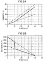
Figur 3 zeigt für ein mittels eines piezoelektrischen Aktors
angetriebenes Antriebselement 3 eine Auftragung des Sekundärhubs
xs gegen den Primärhub xp (Figur 3a), eine Auftragung
der sekundären Antriebskraft Fs des Hubelementes 1 gegen den
Primärhub xp (Figur 3b) und eine Auftragung der sekundären
Antriebskraft Fs gegen den Sekundärhub xs (Figur 3c), jeweils
für einen reinen Hebelantrieb mit Hubfaktor Π = 2 (grob gestrichelt),
einen reinen mechanischen Direktantrieb (fein gestrichelt)
mit Hubfaktor Π = 1 und einen Hubübertrager nach
Figur 1 und 2 mit Hubfaktor Π = 1 und Π = 2 (durchgezogene
Linie).Figure 3 shows a by means of a piezoelectric actuator
driven
In Figur 3a wird dokumentiert, daß anfänglich der Hubübertrager mit dem gleichen Hubfaktor Π = 1 überträgt wie der Direktantrieb und nach Erreichen des Umschaltpunktes xt = 10 (in beliebigen Einheiten) auf den Hubfaktor Π = 2 des Hebelantriebs umschaltet.In Figure 3a it is documented that initially the stroke transmitter with the same stroke factor Π = 1 as the Direct drive and after reaching the switchover point xt = 10 (in any units) to the stroke factor Π = 2 of the lever drive toggles.
Figur 3b zeigt, daß bis zum Erreichen des Umschaltpunktes xt die Werte des Hubübertragers denjenigen des Direktantriebs entsprechen und nach Erreichen des Umschaltpunktes xt schnell auf die Werte des reinen Hebelantriebs abfallen.Figure 3b shows that until the switch point xt is reached the values of the stroke transmitter are those of the direct drive correspond and quickly after reaching the switching point xt drop to the values of the pure lever drive.
In Figur 3c wird gezeigt, daß nach Erreichen des Umschaltpunktes
xt die sekundäre Antriebskraft Es des Hubübertragers
unter den Wert für den Hebelantrieb absinkt, wobei der Unterschied
aufgrund des ursprünglichen Abstands h zwischen Hebel
2 und Hubelement 1 am Hubübertrager zustande kommt.In Figure 3c it is shown that after reaching the switch point
xt is the secondary driving force Es of the stroke transmitter
drops below the value for the lever drive, the difference
due to the original distance h between
Es ist somit aus den Figuren 3a bis 3c klar ersichtlich, daß mittels des Hubübertragers zu Beginn des Betätigungsvorgangs eine hohe Kraft übertragbar ist, und nach Umschalten auf eine rein hebelunterstützte Antriebsweise die Wegcharakteristik eines reinen Hebelantriebs ausgenutzt wird.It can thus be clearly seen from FIGS. 3a to 3c that by means of the stroke transmitter at the beginning of the actuation process a high force is transferable, and after switching to one purely lever-assisted drive mode the path characteristic a pure lever drive is used.
Figur 4 zeigt als Schnittdarstellung in Seitenansicht ein weiteres Ausführungsbeispiel eines Hubübertragers in Ausgangsstellung.Figure 4 shows a sectional side view Another embodiment of a stroke transmitter in the starting position.
In Ausgangsstellung liegen die mindestens zwei Hebel 2 an einem
inneren Krafteinleitungspunkt 71 auf dem Antriebselement
3 auf. Gleichzeitig liegt das Hubelement 1 an jeweils einem
Hubpunkt 6 auf den Hebeln 2 und an einem Drehpunkt 5 auf dem
Lager 4 auf. Somit wird durch die Hebel 2 ein mechanischer
Kraftschluß zwischen dem Antriebselement 3 und dem Hubelement
1 vermittelt.In the starting position, the at least two
Der innere Krafteinleitungspunkt 71 und der Hubpunkt 6 eines
Hebels 2 liegen auf einer zur Rotationsachse I parallelen Linie.
Dadurch wird erreicht, daß bei Aufsatz des Hebels 2 nur
am inneren Krafteinleitungspunkt 71 die Länge L1 des Kraftarms
der gesamten wirksamen Hebellänge L1+L2 entspricht, so
daß wegen der fehlenden Hebelwirkung eine neutrale Hubübertragung
Π = 1 auftritt.The inner
Bei einem Betätigungsvorgang wird das Antriebselement 3 entlang
der Rotationsachse I relativ zum Lager 4 verschoben.
Weil die Länge L1 des Kraftarms gleich der wirksamen Länge
L1+L2 des Hebel 2 ist, wird mittels der Hebel 2 keine
Hebelwirkung erzeugt, sondern der Primärhub xp direkt
hubverlustfrei auf das Hubelement 1 übertragen. Gleichzeitig
werden durch die Bewegung des Hubelementes 3 relativ zu den
Lagern 4 die Hebel 2 in Richtung des Antriebselementes 3
verdreht, wobei der innere Krafteinleitungspunkt 71 als
Angelpunkt wirkt.During an actuation process, the
Sobald der Primärhub xp so groß ist, daß die Hebel 2 auf einem
anderen, äußeren Krafteinleitungspunkt 72, ..., 7n (n ∈
Durch die Hebel 2 ist also ein Hubfaktor
The
In diesem Ausführungsbeispiel existiert genau ein weiterer
Krafteinleitungspunkt 72, der weiter von der Rotationsachse I
entfernt ist als der innere Krafteinleitungpunkt 71. Es können
aber in einer anderen Aufführungsform beliebige n äußere
Krafteinleitungspunkte 71, 72, ... ,7n verwendet werden, wobei
gewöhnlich n mit der Entfernung von der Rotationsachse I
wächst.In this embodiment there is exactly one more
Bei weiterer Verschiebung des Antriebselementes 3 nach Aufsetzen
auf einen äußeren Krafteinleitungspunkt 72,...,7(n-1)
kann jeder Hebel 2 sukzessive auf weitere äußere Krafteinleitungspunkte
73, ..., 7n aufsetzen, wobei sich jedesmal die
Länge des Kraftarmes L1 sprungartig verringert. Mittels einer
solchen Anordnung können n Hubverhältnisse Π in Abhängigkeit
vom Primärhub xp eingestellt werden.With further displacement of the
In Figur 5 ist in Ausgangsstellung ein weiteres Ausführungsbeispiel als Schnittdarstellung in Seitenansicht dargestellt.5 shows another embodiment in the starting position shown as a sectional view in side view.
Hier sind im Gegensatz zu Figur 4 keine diskreten Krafteinleitungspunkte
71, ..., 7n mehr vorhanden, vielmehr setzen
die Hebel 2 auf einer gekrümmten Fläche des Antriebselementes
3 auf, was einer Zuordnung n → ∞ entspricht.In contrast to FIG. 4, there are no discrete force introduction points
71, ..., 7n more available, rather set
the
Dadurch wird erreicht, daß bei einer Verschiebung des Antriebselementes 3 eine kontinuierliche Änderung der Länge L1 des Kraftarms möglich ist. This ensures that when the drive element is displaced 3 a continuous change in length L1 of the power arm is possible.
Dabei kann die Oberfläche auch so gekrümmt sein, daß bei einer
Verschiebung des Antriebselementes 3 eine neutrale
Hubübertragung stattfindet.
Auch kann die Oberfläche so geformt sein, daß sich der Hubfaktor
Π lediglich abschnittsweise stetig ändert, beispielsweise
indem die Oberfläche in Richtung des Hubelementes 1 abschnittsweise
konkav und konvex ausgebildet ist.The surface can also be curved such that a neutral stroke transmission takes place when the
The surface can also be shaped such that the stroke factor Π only changes continuously in sections, for example in that the surface is concave and convex in sections in the direction of the
Es ist zur verbesserten Variation des Hubfaktors Π vorteilhaft,
wenn der mindestens eine Hebel 2 ebenfalls eine gekrümmte,
mindestens auf einem Kontaktpunkt 5,6,7,71, ...,
7n,71', ... , 7n' aufliegende Oberfläche aufweist.To improve the variation of the stroke factor Π, it is advantageous
if the at least one
Es ist weiterhin vorteilhaft, wenn genau ein Hebel 2 eingesetzt
wir, weil dann eine Justage mehrerer Hebel 2 zur
Sicherstellung einer gleichen Hebelwirkung entfällt. Eine
mögliche Dezentrierung des Hubelementes 1 kann mittels einer
Führung des Hubelementes 1, z. B. in einer Bohrung, weitgehend
ausgeglichen werden.It is also advantageous if exactly one
Als Hebellager eignen sich alle aus der Hebeltechnik bekannten
Ausführungen, z. B. Schneidenlager oder Rollen- und Biegelager
sowie Kombinationen derselben.
Auch kann ein anfänglicher direkter Kraftschluß zwischen Antriebselement
(3) und Hubelement (1) auch über seitlich an
den Hebeln (2) vorbeiführenden Nocken erfolgen.All versions known from lever technology are suitable as lever bearings, e.g. B. cutting edge bearings or roller and bending bearings and combinations thereof.
An initial direct frictional connection between the drive element (3) and the lifting element (1) can also take place via cams passing laterally past the levers (2).
Claims (14)
wobei
in which
wobei
in which
Applications Claiming Priority (2)
| Application Number | Priority Date | Filing Date | Title |
|---|---|---|---|
| DE19858758 | 1998-12-18 | ||
| DE19858758A DE19858758C1 (en) | 1998-12-18 | 1998-12-18 | Stroke transmission device and method |
Publications (3)
| Publication Number | Publication Date |
|---|---|
| EP1010877A2 true EP1010877A2 (en) | 2000-06-21 |
| EP1010877A3 EP1010877A3 (en) | 2001-06-27 |
| EP1010877B1 EP1010877B1 (en) | 2004-03-24 |
Family
ID=7891763
Family Applications (1)
| Application Number | Title | Priority Date | Filing Date |
|---|---|---|---|
| EP99125229A Expired - Lifetime EP1010877B1 (en) | 1998-12-18 | 1999-12-17 | Stroke transmission |
Country Status (3)
| Country | Link |
|---|---|
| US (1) | US6367350B1 (en) |
| EP (1) | EP1010877B1 (en) |
| DE (2) | DE19858758C1 (en) |
Families Citing this family (2)
| Publication number | Priority date | Publication date | Assignee | Title |
|---|---|---|---|---|
| GB0217734D0 (en) * | 2002-07-31 | 2002-09-11 | Pbt Ip Ltd | Reversing linkage |
| DE502005010937D1 (en) * | 2005-09-06 | 2011-03-17 | Continental Automotive Gmbh | Fuel injection valve |
Citations (5)
| Publication number | Priority date | Publication date | Assignee | Title |
|---|---|---|---|---|
| FR988675A (en) * | 1949-04-13 | 1951-08-30 | Cie Francaise Du Signum | Improvements to mechanical triggering devices |
| DE2652029A1 (en) * | 1976-11-15 | 1978-05-18 | Bosch Siemens Hausgeraete | Boiling plate with temperature sensor - has bimetal discs in hub of plate operating transmission component moving switch contacts |
| EP0531749A1 (en) * | 1991-09-07 | 1993-03-17 | Heidelberger Druckmaschinen Aktiengesellschaft | Force amplifying device |
| DE4306072A1 (en) * | 1993-02-26 | 1994-09-08 | Siemens Ag | Device for opening and closing a passage opening in a housing |
| DE19519191A1 (en) * | 1995-05-24 | 1996-12-19 | Siemens Ag | Injector |
Family Cites Families (18)
| Publication number | Priority date | Publication date | Assignee | Title |
|---|---|---|---|---|
| US2649815A (en) * | 1947-12-12 | 1953-08-25 | Kaye & Macdonald Inc | Lever system for steam traps |
| US3045500A (en) * | 1960-08-25 | 1962-07-24 | United Aircraft Corp | Rate device |
| DE2913506A1 (en) * | 1979-04-04 | 1980-10-16 | Amsted Siemag Kette Gmbh | POWER AMPLIFIER |
| EP0042378B1 (en) * | 1979-12-26 | 1984-07-04 | Caterpillar Tractor Co. | Method and apparatus for assembly of a track chain |
| DE3342951C2 (en) * | 1983-11-26 | 1986-12-18 | Daimler-Benz Ag, 7000 Stuttgart | Actuating device for two valves that can be actuated independently of one another |
| US4609178A (en) * | 1984-02-02 | 1986-09-02 | Baumann Hans D | Diaphragm type control valve |
| FR2580069B1 (en) * | 1985-04-03 | 1987-05-29 | Seb Sa | |
| US4791824A (en) * | 1987-01-28 | 1988-12-20 | Delphin Corporation | Hydraulic assisted machine |
| DE3800203C2 (en) * | 1988-01-07 | 1997-08-14 | Atlas Fahrzeugtechnik Gmbh | Fuel injector |
| DE3920931A1 (en) * | 1989-06-27 | 1991-01-03 | Fev Motorentech Gmbh & Co Kg | ELECTROMAGNETIC OPERATING DEVICE |
| FR2649540B1 (en) * | 1989-07-06 | 1991-10-18 | Europ Agence Spatiale | MECHANISM FOR THE ADJUSTMENT OF THE ORIENTATION AND / OR THE POSITION OF A PAYLOAD |
| US5215286A (en) * | 1992-05-26 | 1993-06-01 | Nupro Company | High pressure diaphragm valve |
| US5251502A (en) * | 1992-06-09 | 1993-10-12 | Savair Inc. | Sequential pivot pin multiplier |
| JP3616855B2 (en) * | 1995-03-13 | 2005-02-02 | 株式会社フジキン | Controller |
| JP3525313B2 (en) * | 1995-06-30 | 2004-05-10 | 太平洋セメント株式会社 | Positioning device with lever displacement enlargement mechanism |
| DE19648730C2 (en) * | 1996-11-25 | 1998-11-19 | Fraunhofer Ges Forschung | Piezo-electrically operated micro valve |
| DE19710601C2 (en) * | 1997-03-14 | 1999-05-20 | Univ Magdeburg Tech | Motion generator |
| US5996432A (en) * | 1997-10-31 | 1999-12-07 | Orbea; Cesar Raul Lopez | Torque variator device |
-
1998
- 1998-12-18 DE DE19858758A patent/DE19858758C1/en not_active Expired - Fee Related
-
1999
- 1999-12-17 DE DE59908945T patent/DE59908945D1/en not_active Expired - Lifetime
- 1999-12-17 EP EP99125229A patent/EP1010877B1/en not_active Expired - Lifetime
- 1999-12-20 US US09/446,405 patent/US6367350B1/en not_active Expired - Lifetime
Patent Citations (5)
| Publication number | Priority date | Publication date | Assignee | Title |
|---|---|---|---|---|
| FR988675A (en) * | 1949-04-13 | 1951-08-30 | Cie Francaise Du Signum | Improvements to mechanical triggering devices |
| DE2652029A1 (en) * | 1976-11-15 | 1978-05-18 | Bosch Siemens Hausgeraete | Boiling plate with temperature sensor - has bimetal discs in hub of plate operating transmission component moving switch contacts |
| EP0531749A1 (en) * | 1991-09-07 | 1993-03-17 | Heidelberger Druckmaschinen Aktiengesellschaft | Force amplifying device |
| DE4306072A1 (en) * | 1993-02-26 | 1994-09-08 | Siemens Ag | Device for opening and closing a passage opening in a housing |
| DE19519191A1 (en) * | 1995-05-24 | 1996-12-19 | Siemens Ag | Injector |
Also Published As
| Publication number | Publication date |
|---|---|
| US6367350B1 (en) | 2002-04-09 |
| EP1010877B1 (en) | 2004-03-24 |
| DE19858758C1 (en) | 2000-09-07 |
| DE59908945D1 (en) | 2004-04-29 |
| EP1010877A3 (en) | 2001-06-27 |
Similar Documents
| Publication | Publication Date | Title |
|---|---|---|
| EP1019628B1 (en) | Device for transmitting displacement, injection valve having such a device and method for the production of a transmission element | |
| EP1252432B1 (en) | Directly controlled fuel injection device for a reciprocating internal combustion engine | |
| AT404288B (en) | ENGINE BRAKE IN AN INTERNAL COMBUSTION ENGINE FOR MOTOR VEHICLES | |
| DE3707046C2 (en) | ||
| DE19653555C2 (en) | Piezoelectric actuator | |
| DE60115766T2 (en) | Self-compensating piezoelectric actuator for a control valve | |
| EP0530785A1 (en) | Dispensing device for fluids | |
| DE19621951C1 (en) | Control device for hydraulic valves, especially in engines | |
| AT519932B1 (en) | High pressure relief valve | |
| WO2002057622A1 (en) | Valve for controlling liquids | |
| WO1999018349A1 (en) | Directly controlled injection valve, especially a fuel injection valve | |
| EP1264968B1 (en) | Apparatus for actuating a valve with variable lift in an internal combustion engine | |
| DE4442965A1 (en) | Switchable valve for internal combustion engine | |
| DE3522313A1 (en) | CONTINUOUSLY VARIABLE V-BELT GEARBOX | |
| EP1010877B1 (en) | Stroke transmission | |
| WO2000055492A1 (en) | Fuel injection valve | |
| WO2010142753A1 (en) | Injection valve comprising a transmission unit | |
| WO1999017004A1 (en) | Tappet for the valve gear of an internal combustion engine | |
| DE4334395C2 (en) | Cam switching mechanism for motors | |
| WO2017207671A1 (en) | Length-adjustable connecting rod, device for setting a compression ratio and internal combustion engine | |
| EP0298076B1 (en) | Electrically controllable fuel injection valve | |
| EP0730097A2 (en) | Starting valve | |
| DE4219435A1 (en) | Switching-off system for IC engine valve - uses bolt with stop insertable via opening in cup tappet | |
| EP0902170B1 (en) | Chain drive tensioner and variator | |
| CH692487A5 (en) | A hydraulic tensioner for removably mounting precision of machine elements. |
Legal Events
| Date | Code | Title | Description |
|---|---|---|---|
| PUAI | Public reference made under article 153(3) epc to a published international application that has entered the european phase |
Free format text: ORIGINAL CODE: 0009012 |
|
| AK | Designated contracting states |
Kind code of ref document: A2 Designated state(s): DE FR IT |
|
| AX | Request for extension of the european patent |
Free format text: AL;LT;LV;MK;RO;SI |
|
| PUAL | Search report despatched |
Free format text: ORIGINAL CODE: 0009013 |
|
| AK | Designated contracting states |
Kind code of ref document: A3 Designated state(s): AT BE CH CY DE DK ES FI FR GB GR IE IT LI LU MC NL PT SE |
|
| AX | Request for extension of the european patent |
Free format text: AL;LT;LV;MK;RO;SI |
|
| 17P | Request for examination filed |
Effective date: 20011217 |
|
| AKX | Designation fees paid |
Free format text: DE FR IT |
|
| GRAP | Despatch of communication of intention to grant a patent |
Free format text: ORIGINAL CODE: EPIDOSNIGR1 |
|
| GRAS | Grant fee paid |
Free format text: ORIGINAL CODE: EPIDOSNIGR3 |
|
| GRAA | (expected) grant |
Free format text: ORIGINAL CODE: 0009210 |
|
| AK | Designated contracting states |
Kind code of ref document: B1 Designated state(s): DE FR IT |
|
| REF | Corresponds to: |
Ref document number: 59908945 Country of ref document: DE Date of ref document: 20040429 Kind code of ref document: P |
|
| ET | Fr: translation filed | ||
| PLBE | No opposition filed within time limit |
Free format text: ORIGINAL CODE: 0009261 |
|
| STAA | Information on the status of an ep patent application or granted ep patent |
Free format text: STATUS: NO OPPOSITION FILED WITHIN TIME LIMIT |
|
| 26N | No opposition filed |
Effective date: 20041228 |
|
| REG | Reference to a national code |
Ref country code: FR Ref legal event code: TP |
|
| REG | Reference to a national code |
Ref country code: FR Ref legal event code: PLFP Year of fee payment: 17 |
|
| REG | Reference to a national code |
Ref country code: FR Ref legal event code: PLFP Year of fee payment: 18 |
|
| REG | Reference to a national code |
Ref country code: FR Ref legal event code: PLFP Year of fee payment: 19 |
|
| PGFP | Annual fee paid to national office [announced via postgrant information from national office to epo] |
Ref country code: FR Payment date: 20181219 Year of fee payment: 20 |
|
| PGFP | Annual fee paid to national office [announced via postgrant information from national office to epo] |
Ref country code: DE Payment date: 20181231 Year of fee payment: 20 Ref country code: IT Payment date: 20181220 Year of fee payment: 20 |
|
| REG | Reference to a national code |
Ref country code: DE Ref legal event code: R071 Ref document number: 59908945 Country of ref document: DE |