EP1010858B1 - Steam cooling a turbine rotor - Google Patents
Steam cooling a turbine rotor Download PDFInfo
- Publication number
- EP1010858B1 EP1010858B1 EP99310130A EP99310130A EP1010858B1 EP 1010858 B1 EP1010858 B1 EP 1010858B1 EP 99310130 A EP99310130 A EP 99310130A EP 99310130 A EP99310130 A EP 99310130A EP 1010858 B1 EP1010858 B1 EP 1010858B1
- Authority
- EP
- European Patent Office
- Prior art keywords
- cooling medium
- tube
- turbine
- end cap
- ring
- Prior art date
- Legal status (The legal status is an assumption and is not a legal conclusion. Google has not performed a legal analysis and makes no representation as to the accuracy of the status listed.)
- Expired - Lifetime
Links
Images


Classifications
-
- F—MECHANICAL ENGINEERING; LIGHTING; HEATING; WEAPONS; BLASTING
- F01—MACHINES OR ENGINES IN GENERAL; ENGINE PLANTS IN GENERAL; STEAM ENGINES
- F01D—NON-POSITIVE DISPLACEMENT MACHINES OR ENGINES, e.g. STEAM TURBINES
- F01D5/00—Blades; Blade-carrying members; Heating, heat-insulating, cooling or antivibration means on the blades or the members
- F01D5/12—Blades
- F01D5/14—Form or construction
- F01D5/18—Hollow blades, i.e. blades with cooling or heating channels or cavities; Heating, heat-insulating or cooling means on blades
- F01D5/185—Liquid cooling
-
- F—MECHANICAL ENGINEERING; LIGHTING; HEATING; WEAPONS; BLASTING
- F02—COMBUSTION ENGINES; HOT-GAS OR COMBUSTION-PRODUCT ENGINE PLANTS
- F02C—GAS-TURBINE PLANTS; AIR INTAKES FOR JET-PROPULSION PLANTS; CONTROLLING FUEL SUPPLY IN AIR-BREATHING JET-PROPULSION PLANTS
- F02C7/00—Features, components parts, details or accessories, not provided for in, or of interest apart form groups F02C1/00 - F02C6/00; Air intakes for jet-propulsion plants
-
- Y—GENERAL TAGGING OF NEW TECHNOLOGICAL DEVELOPMENTS; GENERAL TAGGING OF CROSS-SECTIONAL TECHNOLOGIES SPANNING OVER SEVERAL SECTIONS OF THE IPC; TECHNICAL SUBJECTS COVERED BY FORMER USPC CROSS-REFERENCE ART COLLECTIONS [XRACs] AND DIGESTS
- Y02—TECHNOLOGIES OR APPLICATIONS FOR MITIGATION OR ADAPTATION AGAINST CLIMATE CHANGE
- Y02T—CLIMATE CHANGE MITIGATION TECHNOLOGIES RELATED TO TRANSPORTATION
- Y02T50/00—Aeronautics or air transport
- Y02T50/60—Efficient propulsion technologies, e.g. for aircraft
Definitions
- the present invention relates generally to turbines and particularly to land-based gas turbines for power generation employing closed-circuit steam-cooling paths for cooling the hot gas components and particularly relates to a bore tube assembly facilitating the supply of cooling steam to the hot gas components and return of the spent cooling steam.
- Steam cooling of hot gas path components has been proposed in the past and found efficacious in land-based power generating plants.
- gas turbines are typically air-cooled, for example, jet engines employ compressor discharge air for cooling the hot gas components
- steam cooling is more efficient in that the losses associated with the use of steam as a coolant are not as great as the losses realised by extracting compressor bleed air for cooling purposes.
- steam cooling is particularly advantageous because the heat energy imparted to the steam as it cools the gas turbine components is recovered as useful work in driving the steam turbine in the combined cycle operation.
- US-A-5 738 488 discloses a steam gland that transfers steam from a stationary pipe to the rotating rotor of a gas turbine. Discrete supply and return bores are formed in a turbine housing for delivering the steam in the required direction relative to the gas turbine rotor.
- a turbine having a rotor rotatable about an axis including a plurality of turbine wheels mounting turbine buckets and a bore tube assembly for conveying a cooling medium to the buckets of at least one of said turbine wheels and conveying spent cooling medium to a return, said bore tube assembly comprising:
- another aspect of the present invention includes an inner core within the end cap.
- the inner core has a shaped head or body for directing the spent cooling steam returning from the steam-cooled buckets radially inwardly through the tubes into the axially directed return passage of the inner tube of the bore assembly.
- the inner core also carries a plurality of vanes for removing any tendency of the returning cooling steam to swirl in the axial return flow passage within the inner tube. That is, the vanes remove the swirling components of flow of the steam and direct the steam substantially in an axial direction.
- a radiation shield overlies at least a portion of the outer tube between it and the aft shaft to minimize heat transfer from the steam supply passage to the aft main bearing.
- the shield per se resists thermal radiation to the aft main bearing which might otherwise obtain a temperature above acceptable limits for the bearing pad and oil film of the bearing.
- an air gap is provided between the bore tube and the radiation shield, enabling the shield to provide thermal resistance to heat transfer by conduction.
- the radiation shield is secured at one end to the outer bore tube, while the other end remains free for axial thermal expansion.
- a strut ring between the inner and outer tubes of the bore tube assembly which enables thermal expansion and contraction of the inner tube relative to the outer tube.
- the strut ring includes inner and outer rings, the outer ring preferably being secured by welding to the inner surface of the outer tube of the bore tube assembly.
- the inner tube is slidable relative to the inner ring of the strut ring to enable thermal axial expansion of the inner tube relative to the strut ring.
- the strut ring maintains the orientation, i.e., the concentricity of the inner tube relative to the outer tube.
- the strut ring includes a plurality of struts extending between the inner and outer rings and which struts are canted off radii of the strut ring.
- the canting of the struts enables limited thermal radial expansion of the inner tube relative to the outer tube while maintaining concentricity of the inner and outer tubes.
- the trailing edges of the struts are angled in an axial downstream direction to shed vortices.
- a turbine having a rotor rotatable about an axis including a plurality of turbine wheels mounting turbine buckets, a bore tube assembly for conveying a cooling medium to the buckets of at least one of the turbine wheels and conveying spent cooling medium to a return, comprising elongated outer and inner tubes spaced from one another and concentric about the axis defining first and second passages for respectively conveying the cooling medium in one axial direction and conveying spent cooling medium in an axial direction opposite the one direction, an end cap adjacent one end of the tube assembly having first and second sets of a plurality each of circumferentially spaced openings in communication with the first and second passages, respectively and first and second sets of a plurality each of circumferentially spaced radially extending passageways carried by the rotor in communication with the respective first and second sets of openings in the end cap for distributing the cooling medium to the buckets of the one turbine wheel and conveying the spent cooling medium through the end cap and bore
- a turbine having a rotor rotatable about an axis including a plurality of turbine wheels mounting turbine buckets, a bore tube assembly for conveying a cooling medium to the buckets of at least one of the turbine wheels and conveying spent cooling medium to a return, comprising elongated outer and inner tubes spaced from one another and concentric about the axis defining first and second passages for respectively conveying the cooling medium in one axial direction and conveying spent cooling medium in an axial direction opposite the one direction, first and second sets of a plurality each of circumferentially spaced generally radially extending passageways carried by the rotor in communication with the respective first and second passages for distributing the cooling medium to the buckets of the one turbine wheel and conveying the spent cooling medium through the end cap and bore tube assembly to the return and a bearing journal surrounding at least in part the outer tube, a radiation shield carried by the outer tube for thermally insulating the bearing journal against heat transfer by radiation from the cooling medium
- a turbine having a rotor rotatable about an axis including a plurality of turbine wheels mounting turbine buckets, a bore tube assembly for conveying a cooling medium to the buckets of at least one of the turbine wheels and conveying spent cooling medium to a return, comprising elongated outer and inner tubes spaced from one another and concentric about the axis defining first and second passages for respectively conveying the cooling medium in one axial direction and conveying spent cooling medium in an axial direction opposite the one direction, a strut ring disposed between the inner and outer tubes and having an outer ring and an inner ring interconnected with one another by a plurality of circumferentially spaced struts, one of the inner ring and the outer ring being fixed to one of the inner tube and the outer tube, respectively, with another of the inner ring and the outer-ring and another of the inner tube and the outer tube being slidable relative to one another.
- the present invention seeks to provide a novel and improved cooling circuit in the bore tube assembly of a turbine rotor enabling efficient supply of a cooling medium to selected hot gas components of the rotor and return of spent cooling steam.
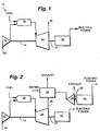
- FIG. 1 is a schematic diagram of a simple cycle, single-shaft heavy-duty gas turbine 10 incorporating the present invention.
- the gas turbine may be considered as comprising a multi-stage axial flow compressor 12 having a rotor shaft 14. Air enters the inlet of the compressor at 16, is compressed by the axial flow compressor 12 and then is discharged to a combustor 18 where fuel such as natural gas is burned to provide high-energy combustion gases which drive the turbine 20. In the turbine 20, the energy of the hot gases is converted into work, some of which is used to drive the compressor 12 through shaft 14, with the remainder being available for useful work to drive a load such as a generator 22 by means of rotor shaft 24 for producing electricity.
- a typical simple cycle gas turbine will convert 30 to 35% of the fuel input into shaft output. All but 1 to 2% of the remainder is in the form of exhaust heat which exits turbine 20 at 26. Higher efficiencies can be obtained by utilizing the gas turbine 10 in a combined cycle configuration in which the energy in the turbine exhaust stream is converted into additional useful work.
- Figure 2 represents a combined cycle in its simplest form, in which the exhaust gases exiting turbine 20 at 26 enter a heat recovery steam generator 28 in which water is converted to steam in the manner of a boiler. Steam thus produced drives one or more steam turbines 30 in which additional work is extracted to drive through shaft 32 an additional load such as a second generator 34 which, in turn, produces additional electric power. In some configurations, turbines 20 and 30 drive a common generator. Combined cycles producing only electrical power are generally in the 50 to 60% thermal efficiency range and using a more advanced gas turbine, of which the present tube assembly forms a part, permits efficiencies in excess of 60%.
- the turbine section 36 includes a number of stages including four successive stages comprising turbine wheels 38, 40, 42 and 44 mounted to and forming part of the rotor shaft for rotation therewith, each carrying a row of buckets, two buckets B being illustrated for wheels 38 and 40, respectively, which buckets project radially outwardly of the wheels.
- the buckets are, of course, arranged alternately between fixed nozzles, also not shown. Between the wheels 38, 40, 42 and 44, there are provided spacer disks 39, 41, 43.
- a coolant supply and return aft disk 45 forming an integral part of an aft shaft 76 is provided on the aft side of the last stage turbine wheel 44. It will be appreciated that the wheels and disks are secured to one another by a plurality of circumferentially spaced, axially extending bolts, not shown, as is conventional in turbine construction.
- a bore tube assembly according to an embodiment of the present invention is generally designated 48.
- Assembly 48 forms part of the rotor, is mounted for rotation about the rotor axis A and is connected to the cooling support and return aft disk 45.
- the bore tube assembly and aft disk 45 cooperate to provide a flow of a cooling medium, e.g., steam, to the turbine buckets of at least one of the turbine stages and preferably to the first two stages of the turbine and a passage for flow of the spent cooling medium, e.g., steam, to a return.
- the cooling system may be provided as part of a closed-circuit steam cooling supply and return system in a combined cycle system, i.e., split off from the high pressure steam turbine exhaust or may be supplied from an existing in-plant supply..
- the bore tube assembly 48 includes an outer tube 50 and an inner tube 52 concentric with outer tube 50 about the axis of rotation of the rotor shaft 24.
- the outer and inner tubes 50 and 52 respectively, define an annular cooling steam supply passage 54, while the inner tube 52 provides a spent cooling steam passage 56.
- a steam gland 58 is disposed about the bore tube assembly. It will be appreciated that the steam gland 58 is fixed and the bore tube assembly rotates about the rotor shaft axis A .
- a steam plenum 60 connected to a supply of steam from a suitable source, not shown, lies in communication with a steam inlet 62 formed through the outer tube 50 for supplying cooling steam to the passage 54 between the outer and inner tubes 50 and 52.
- Labyrinth-type seals 64 and 66 are provided on opposite sides of the steam gland 58 for sealing about the outer tube 50.
- a variation on this design could employ brush seals instead of labyrinth seals.
- the aft end of the steam gland 58 is connected with a stationary steam pipe schematically illustrated by return R for the flowing spent cooling steam.
- the steam gland also includes leakage steam plenums 70 and 72 for collecting steam leaking past the labyrinth seals such that the steam will not flow forwardly to the aft main bearing 74.
- the bearing 74 is a conventional bearing and includes the aft shaft 76, integral with disk 48, shaft 76 being rotatable with the bore tube assembly 48.
- Various seals are disposed at opposite ends of the aft main bearing cooperate with the aft shaft to seal the main bearing.
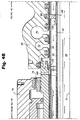
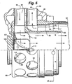
- the forward end of the bore tube assembly includes an end cap, generally designated 80.
- End cap 80 includes an outer generally cylindrical member secured to the aft disk 45 and having a closed end 82 and an opposite open end secured, e.g., by welding, to the outer tube 50 of the bore tube assembly.
- Forming an integral part of the end cap 80 are cylindrical outer and inner sleeves 83 and 84.
- the aft end 86 of inner sleeve 84 is secured to the forward end of the inner tube 52.
- the aft end of the outer sleeve 83 is secured, e.g., by welding, to the forward end of the outer tube 50. Consequently, the cylindrical open end of the end cap defines continuations of the coolant supply passage 54 and spent coolant return passage 56.
- a first set of a plurality of circumferentially spaced openings 88 lying in a diametrical plane about axis A are provided about the outer sleeve 83 of the end cap 80.
- the openings 88 lie in communication with the first passage 54 of the bore tube assembly and its continuation through the concentric inner and outer sleeves of the end cap.
- a second set of circumferentially spaced openings 90 preferably axially spaced from the first set of openings 88, and also lying in a second diametrical plane, is provided adjacent the forward end of end cap 80.
- the second set of openings 90 lie in communication with the spent coolant return passage 56 via inner sleeve 84.
- a plurality of circumferentially spaced, radially extending tubes 92 are disposed in the aft disk 45 and lie in respective communication with the first set of openings 88 of end cap 80.
- the opposite ends of the tubes 92 of the first set thereof lie in communication with supply tubes 94 ( Figure 3) extending within the rotor in an axial direction for supplying steam to the buckets of at least the first-stage turbine wheel, preferably both the first and second stage turbine wheels, for cooling the buckets thereof.
- a second set of a plurality of circumferentially spaced tubes 94 extend radially in the aft disk 45 in communication at their radial inner ends with respective openings 90 of the end cap 80.
- the second set of tubes 94 lie in communication with return tubes 96 also extending within the rotor in an axial direction for returning spent cooling steam from the cooled buckets to the tubes 94 and into the end cap 80 by way of openings 90.
- the tubes 92 and 94 thus constitute first and second axially spaced sets of a plurality each of circumferentially spaced extending passageways 93, 95 in communication with the respective first and second sets of openings 88, 90 in the end cap for respectively conveying cooling medium from passage 54 through end cap 80 to the buckets and returning spent cooling medium from the buckets through the bore tube assembly, including end cap 80 and inner tube 52, along passage 56.
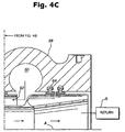
- Inner core 100 Within the end cap assembly, there is provided an inner core 100.
- Inner core 100 includes a central body 102 having a flat base 104 for securement to the inside end face of the end cap 80 by bolted connections, five bolt holes 103 being illustrated in Figures 6 and 7 (a single bolt 101 therefor being illustrated in Figures 4A and 5).
- the inner core 100 is a forged piece, preferably formed of Inconel 718. Casting of the inner core is an alternative method. Additionally, two dowel pins, one being illustrated at 106 in each of Figures 4A and 5, are employed to carry the shear load between the inner core 100 and end cap 80, the bolts 101 carrying the tension load.
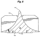
- the body 102 of the inner core 100 is generally arcuate and conically-shaped terminating in an apex 110, the axis of the conical body 102 lying on the rotor axis A. Additionally, as illustrated in Figures 7 and 8, a plurality of vanes 112 are provided extending from the curved conical body 102 to the margin of the inner core 100. As illustrated in Figures 4A and 5, and with the inner core 100 secured to the interior face of the end cap 80, it will be appreciated that the inner core 100 resides wholly within inner sleeve 84. Also, the vanes 112 are spaced from one another such that the return flow through tubes 94 flows between the vanes.
- the aft shaft is secured to the bore tube assembly by a pair of forward and aft interference fits.
- the forward interference fit is indicated at 120 in Figure 4A
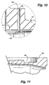
- the aft interference fit is indicated at 122 in Figure 4B.
- the bore tube assembly must be held centered and attached to the aft shaft at all operating conditions of the turbine. Otherwise, destructive imbalance and subsequent vibrations could occur.
- a pair of interference fits between the aft shaft and the bore tube assembly at opposite ends of the aft shaft prevent such imbalance and vibration.
- the bore tube assembly must be prevented from twisting within the aft shaft. This is accomplished by using radial pins through the aft shaft engaging the forward end of the bore assembly.
- the aft shaft 76 has a plurality of apertures 126 at circumferentially spaced locations for receiving pins 128.
- the inner ends of the pins 128 engage in circumferentially spaced recesses 130 formed on the outer peripheral surface of the outer sleeve 83 of the end cap 80. It will be appreciated that these pins engaging in the recesses prevent both circumferential and axial movement of the aft shaft relative to the bore tube assembly.
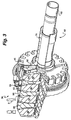
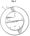
- a strut ring is disposed between the outer and inner tubes 50 and 52, respectively.
- the strut ring includes an outer ring 132 and an inner ring 134 connected one to the other by a plurality of circumferentially spaced struts 136.
- the outer ring 132 is preferably secured to the outer tube 50, for example, by welding.
- the inner ring 134 is slidably connected to the inner tube 52.
- the reverse arrangement is also possible, i.e., the inner ring being secured to the inner tube and the outer ring being slidable relative to the outer tube, but is not preferred.
- the inner tube is maintained concentric with the outer tube 50 while simultaneously thermal expansion of the inner tube in an axial direction is accommodated by relative sliding movement between tube 52 and inner ring 134.
- the inner and outer tubes are fixed to the rotor at their forward ends and, consequently, the inner tube can axially expand in an aft direction relative to the outer tube.
- the fit between the inner ring 134 and the inner tube 52 includes a hard surface coating ground to very close tolerances.
- the struts 136 extend between the inner and outer rings 134 and 132, respectively, at angles inclined to the radii, as illustrated in Figure 2. That is, acute angles form between radii of the strut ring and the struts 136.
- the otherwise generally radial forces applied to the radial extending struts 136 by radial outward thermal expansion of the inner tube 52 are mitigated by angling the struts relative to the radii.
- the inner ring 134 tends to rotate slightly and the struts tend to flex as the inner tube 52 expands in a radial direction under thermal loading.
- the upstream or leading edges of the struts 136 lie generally in a plane normal to the axis of the flow passage 54.
- the trailing edges of struts 136 are angled relative to the axis, i.e., angled in a direction generally radially outwardly from the inner tube and in a downstream direction. That is, with the leading edges extending normal to the axis, the trailing edges are canted so that the outer diameter of each strut has a longer axial length than its inner diameter.
- the particular shape of the struts is significant as the struts in this configuration and orientation tend to reduce vortex shedding and vibration as the cooling steam flows along passage 54.
- FIG. 4B there is also a plurality of air inlet passages 140 through the aft shaft 76.
- a thermal radiation shield 142 is disposed about outer tube 50 and is spaced from the aft shaft 76 to provide an axially extending concentric gap for receiving the air flow from air passages 140.
- the air passing through this annular air passage exits the rotor through a plurality of holes in the same axial plane as the pins 128 at the forward end of the bore tube assembly.
- An annular air gap lies between the thermal radiation shield 142 and outer bore tube 50. Consequently, the shield 142 precludes heat transfer by radiation from the cooling steam in passage 54 to the aft main bearing. Also, the air gap and the air passage form thermal insulators between the cooling steam in passage 54 and the main bearing.
Landscapes
- Engineering & Computer Science (AREA)
- Mechanical Engineering (AREA)
- General Engineering & Computer Science (AREA)
- Chemical & Material Sciences (AREA)
- Combustion & Propulsion (AREA)
- Turbine Rotor Nozzle Sealing (AREA)
Applications Claiming Priority (2)
| Application Number | Priority Date | Filing Date | Title |
|---|---|---|---|
| US21636398A | 1998-12-18 | 1998-12-18 | |
| US216363 | 1998-12-18 |
Publications (3)
| Publication Number | Publication Date |
|---|---|
| EP1010858A2 EP1010858A2 (en) | 2000-06-21 |
| EP1010858A3 EP1010858A3 (en) | 2002-06-19 |
| EP1010858B1 true EP1010858B1 (en) | 2006-02-01 |
Family
ID=22806757
Family Applications (1)
| Application Number | Title | Priority Date | Filing Date |
|---|---|---|---|
| EP99310130A Expired - Lifetime EP1010858B1 (en) | 1998-12-18 | 1999-12-15 | Steam cooling a turbine rotor |
Country Status (5)
| Country | Link |
|---|---|
| US (1) | US6435812B1 (ja) |
| EP (1) | EP1010858B1 (ja) |
| JP (1) | JP4308388B2 (ja) |
| KR (1) | KR100592134B1 (ja) |
| DE (1) | DE69929666T2 (ja) |
Families Citing this family (10)
| Publication number | Priority date | Publication date | Assignee | Title |
|---|---|---|---|---|
| JP4527824B2 (ja) | 1998-12-22 | 2010-08-18 | ゼネラル・エレクトリック・カンパニイ | タービンロータの軸受用冷却系 |
| JP4690531B2 (ja) * | 1999-09-27 | 2011-06-01 | 三菱重工業株式会社 | ガスタービンのロータ尾端部の軸構造 |
| DE60132642T2 (de) * | 2000-09-26 | 2008-05-21 | Mitsubishi Heavy Industries, Ltd. | Wellen- und Lageranordnung für eine dampfgekühlte Gasturbine |
| JP3481596B2 (ja) * | 2001-02-14 | 2003-12-22 | 株式会社日立製作所 | ガスタービン |
| US20040256807A1 (en) * | 2003-06-23 | 2004-12-23 | Nitin Bhate | Retrofittable non-metallic brush seal assembly |
| US6984101B2 (en) * | 2003-07-14 | 2006-01-10 | Siemens Westinghouse Power Corporation | Turbine vane plate assembly |
| US7344354B2 (en) * | 2005-09-08 | 2008-03-18 | General Electric Company | Methods and apparatus for operating gas turbine engines |
| US8267649B2 (en) * | 2009-05-15 | 2012-09-18 | General Electric Company | Coupling for rotary components |
| US9574453B2 (en) | 2014-01-02 | 2017-02-21 | General Electric Company | Steam turbine and methods of assembling the same |
| US11078843B2 (en) | 2018-05-31 | 2021-08-03 | Raytheon Technologies Corporation | Thermal management of a gas turbine engine shaft |
Family Cites Families (10)
| Publication number | Priority date | Publication date | Assignee | Title |
|---|---|---|---|---|
| US5144794A (en) * | 1989-08-25 | 1992-09-08 | Hitachi, Ltd. | Gas turbine engine with cooling of turbine blades |
| GB2239491B (en) * | 1989-11-28 | 1993-09-29 | Copermill Ltd | Hot gas blower |
| US5593274A (en) | 1995-03-31 | 1997-01-14 | General Electric Co. | Closed or open circuit cooling of turbine rotor components |
| KR100389990B1 (ko) * | 1995-04-06 | 2003-11-17 | 가부시끼가이샤 히다치 세이사꾸쇼 | 가스터빈 |
| JP3448145B2 (ja) * | 1995-11-24 | 2003-09-16 | 三菱重工業株式会社 | 熱回収式ガスタービンロータ |
| JPH09256815A (ja) * | 1996-03-21 | 1997-09-30 | Toshiba Corp | 蒸気冷却ガスタービン,このガスタービンを用いた蒸気冷却コンバインドサイクルプラントおよびその運転方法 |
| US5738488A (en) * | 1996-11-12 | 1998-04-14 | General Electric Co. | Gland for transferring cooling medium to the rotor of a gas turbine |
| JP4021968B2 (ja) * | 1997-03-12 | 2007-12-12 | 三菱重工業株式会社 | ガスタービンの冷却装置 |
| JP3567065B2 (ja) * | 1997-07-31 | 2004-09-15 | 株式会社東芝 | ガスタービン |
| CA2262050C (en) * | 1998-02-17 | 2003-07-08 | Mitsubishi Heavy Industries, Ltd. | Steam-cooling type gas turbine |
-
1999
- 1999-11-30 JP JP33899199A patent/JP4308388B2/ja not_active Expired - Fee Related
- 1999-12-15 EP EP99310130A patent/EP1010858B1/en not_active Expired - Lifetime
- 1999-12-15 KR KR1019990057790A patent/KR100592134B1/ko not_active IP Right Cessation
- 1999-12-15 DE DE69929666T patent/DE69929666T2/de not_active Expired - Lifetime
-
2000
- 2000-05-09 US US09/566,726 patent/US6435812B1/en not_active Expired - Fee Related
Also Published As
| Publication number | Publication date |
|---|---|
| US6435812B1 (en) | 2002-08-20 |
| DE69929666T2 (de) | 2006-09-21 |
| KR100592134B1 (ko) | 2006-06-23 |
| JP4308388B2 (ja) | 2009-08-05 |
| EP1010858A2 (en) | 2000-06-21 |
| JP2000297659A (ja) | 2000-10-24 |
| EP1010858A3 (en) | 2002-06-19 |
| KR20000048150A (ko) | 2000-07-25 |
| DE69929666D1 (de) | 2006-04-13 |
Similar Documents
| Publication | Publication Date | Title |
|---|---|---|
| US5593274A (en) | Closed or open circuit cooling of turbine rotor components | |
| US6382903B1 (en) | Rotor bore and turbine rotor wheel/spacer heat exchange flow circuit | |
| US6397604B2 (en) | Cooling supply system for stage 3 bucket of a gas turbine | |
| JP3863938B2 (ja) | 動翼先端間隙を制御し得る除去自在タービン内殻 | |
| US6450758B1 (en) | Cooling system for a bearing of a turbine rotor | |
| US7048496B2 (en) | Turbine cooling, purge, and sealing system | |
| EP1101897B1 (en) | Methods for disassembling, replacing and assembling parts of a steam cooling system for a gas turbine | |
| EP1079069B1 (en) | Steam cooling system for a gas turbine | |
| EP1010858B1 (en) | Steam cooling a turbine rotor | |
| EP0841471B1 (en) | Gas turbine and gland transferring cooling medium to the rotor thereof | |
| EP0993543B1 (en) | Cooling scheme for turbine hot parts | |
| US20080022693A1 (en) | Ceramic blade gas turbine |
Legal Events
| Date | Code | Title | Description |
|---|---|---|---|
| PUAI | Public reference made under article 153(3) epc to a published international application that has entered the european phase |
Free format text: ORIGINAL CODE: 0009012 |
|
| AK | Designated contracting states |
Kind code of ref document: A2 Designated state(s): AT BE CH CY DE DK ES FI FR GB GR IE IT LI LU MC NL PT SE |
|
| AX | Request for extension of the european patent |
Free format text: AL;LT;LV;MK;RO;SI |
|
| PUAL | Search report despatched |
Free format text: ORIGINAL CODE: 0009013 |
|
| AK | Designated contracting states |
Kind code of ref document: A3 Designated state(s): AT BE CH CY DE DK ES FI FR GB GR IE IT LI LU MC NL PT SE |
|
| AX | Request for extension of the european patent |
Free format text: AL;LT;LV;MK;RO;SI |
|
| 17P | Request for examination filed |
Effective date: 20021219 |
|
| AKX | Designation fees paid |
Designated state(s): CH DE FR GB IT LI |
|
| 17Q | First examination report despatched |
Effective date: 20030403 |
|
| GRAP | Despatch of communication of intention to grant a patent |
Free format text: ORIGINAL CODE: EPIDOSNIGR1 |
|
| GRAS | Grant fee paid |
Free format text: ORIGINAL CODE: EPIDOSNIGR3 |
|
| GRAA | (expected) grant |
Free format text: ORIGINAL CODE: 0009210 |
|
| AK | Designated contracting states |
Kind code of ref document: B1 Designated state(s): CH DE FR GB IT LI |
|
| REG | Reference to a national code |
Ref country code: GB Ref legal event code: FG4D |
|
| REG | Reference to a national code |
Ref country code: CH Ref legal event code: NV Representative=s name: SERVOPATENT GMBH Ref country code: CH Ref legal event code: EP |
|
| REF | Corresponds to: |
Ref document number: 69929666 Country of ref document: DE Date of ref document: 20060413 Kind code of ref document: P |
|
| ET | Fr: translation filed | ||
| PLBE | No opposition filed within time limit |
Free format text: ORIGINAL CODE: 0009261 |
|
| STAA | Information on the status of an ep patent application or granted ep patent |
Free format text: STATUS: NO OPPOSITION FILED WITHIN TIME LIMIT |
|
| 26N | No opposition filed |
Effective date: 20061103 |
|
| REG | Reference to a national code |
Ref country code: CH Ref legal event code: PFA Owner name: GENERAL ELECTRIC COMPANY Free format text: GENERAL ELECTRIC COMPANY#1 RIVER ROAD#SCHENECTADY, NY 12345 (US) -TRANSFER TO- GENERAL ELECTRIC COMPANY#1 RIVER ROAD#SCHENECTADY, NY 12345 (US) |
|
| PGFP | Annual fee paid to national office [announced via postgrant information from national office to epo] |
Ref country code: GB Payment date: 20131227 Year of fee payment: 15 Ref country code: DE Payment date: 20131230 Year of fee payment: 15 Ref country code: CH Payment date: 20131230 Year of fee payment: 15 |
|
| PGFP | Annual fee paid to national office [announced via postgrant information from national office to epo] |
Ref country code: FR Payment date: 20131217 Year of fee payment: 15 Ref country code: IT Payment date: 20131228 Year of fee payment: 15 |
|
| REG | Reference to a national code |
Ref country code: DE Ref legal event code: R119 Ref document number: 69929666 Country of ref document: DE |
|
| REG | Reference to a national code |
Ref country code: CH Ref legal event code: PL |
|
| GBPC | Gb: european patent ceased through non-payment of renewal fee |
Effective date: 20141215 |
|
| REG | Reference to a national code |
Ref country code: FR Ref legal event code: ST Effective date: 20150831 |
|
| PG25 | Lapsed in a contracting state [announced via postgrant information from national office to epo] |
Ref country code: CH Free format text: LAPSE BECAUSE OF NON-PAYMENT OF DUE FEES Effective date: 20141231 Ref country code: DE Free format text: LAPSE BECAUSE OF NON-PAYMENT OF DUE FEES Effective date: 20150701 Ref country code: LI Free format text: LAPSE BECAUSE OF NON-PAYMENT OF DUE FEES Effective date: 20141231 Ref country code: GB Free format text: LAPSE BECAUSE OF NON-PAYMENT OF DUE FEES Effective date: 20141215 |
|
| PG25 | Lapsed in a contracting state [announced via postgrant information from national office to epo] |
Ref country code: FR Free format text: LAPSE BECAUSE OF NON-PAYMENT OF DUE FEES Effective date: 20141231 |
|
| PG25 | Lapsed in a contracting state [announced via postgrant information from national office to epo] |
Ref country code: IT Free format text: LAPSE BECAUSE OF NON-PAYMENT OF DUE FEES Effective date: 20141215 |