EP1010804B1 - Verfahren und Vorrichtung zur Behandlung von Ausschuss - Google Patents
Verfahren und Vorrichtung zur Behandlung von Ausschuss Download PDFInfo
- Publication number
- EP1010804B1 EP1010804B1 EP99123123A EP99123123A EP1010804B1 EP 1010804 B1 EP1010804 B1 EP 1010804B1 EP 99123123 A EP99123123 A EP 99123123A EP 99123123 A EP99123123 A EP 99123123A EP 1010804 B1 EP1010804 B1 EP 1010804B1
- Authority
- EP
- European Patent Office
- Prior art keywords
- broke
- filtrate
- thickening
- treating
- defiberizing
- Prior art date
- Legal status (The legal status is an assumption and is not a legal conclusion. Google has not performed a legal analysis and makes no representation as to the accuracy of the status listed.)
- Expired - Lifetime
Links
- 238000000034 method Methods 0.000 title claims abstract description 53
- 230000008719 thickening Effects 0.000 claims abstract description 38
- 239000000123 paper Substances 0.000 claims abstract description 27
- 238000004519 manufacturing process Methods 0.000 claims abstract description 18
- 239000000463 material Substances 0.000 claims abstract description 15
- 239000011087 paperboard Substances 0.000 claims abstract description 13
- 239000000706 filtrate Substances 0.000 claims description 43
- XLYOFNOQVPJJNP-UHFFFAOYSA-N water Substances O XLYOFNOQVPJJNP-UHFFFAOYSA-N 0.000 claims description 27
- 239000007788 liquid Substances 0.000 claims description 24
- 238000010790 dilution Methods 0.000 claims description 23
- 239000012895 dilution Substances 0.000 claims description 23
- 238000003860 storage Methods 0.000 claims description 14
- 238000011084 recovery Methods 0.000 claims description 9
- 238000007865 diluting Methods 0.000 claims description 7
- 238000000926 separation method Methods 0.000 description 8
- 239000000047 product Substances 0.000 description 5
- 230000004087 circulation Effects 0.000 description 4
- 230000012010 growth Effects 0.000 description 4
- 239000000725 suspension Substances 0.000 description 4
- 230000003247 decreasing effect Effects 0.000 description 3
- 238000009966 trimming Methods 0.000 description 2
- 239000003643 water by type Substances 0.000 description 2
- 229920002472 Starch Polymers 0.000 description 1
- 239000011230 binding agent Substances 0.000 description 1
- 230000033228 biological regulation Effects 0.000 description 1
- 239000011248 coating agent Substances 0.000 description 1
- 238000000576 coating method Methods 0.000 description 1
- 238000011109 contamination Methods 0.000 description 1
- 238000005520 cutting process Methods 0.000 description 1
- 230000007423 decrease Effects 0.000 description 1
- 230000001934 delay Effects 0.000 description 1
- 230000007613 environmental effect Effects 0.000 description 1
- 230000002349 favourable effect Effects 0.000 description 1
- 239000013505 freshwater Substances 0.000 description 1
- 239000001963 growth medium Substances 0.000 description 1
- 239000012535 impurity Substances 0.000 description 1
- 239000002245 particle Substances 0.000 description 1
- 238000003825 pressing Methods 0.000 description 1
- 230000003134 recirculating effect Effects 0.000 description 1
- 229920005989 resin Polymers 0.000 description 1
- 239000011347 resin Substances 0.000 description 1
- 239000007787 solid Substances 0.000 description 1
- 235000019698 starch Nutrition 0.000 description 1
- 239000002699 waste material Substances 0.000 description 1
Images

Classifications
-
- D—TEXTILES; PAPER
- D21—PAPER-MAKING; PRODUCTION OF CELLULOSE
- D21F—PAPER-MAKING MACHINES; METHODS OF PRODUCING PAPER THEREON
- D21F1/00—Wet end of machines for making continuous webs of paper
- D21F1/66—Pulp catching, de-watering, or recovering; Re-use of pulp-water
Definitions
- the present invention relates to a method of and apparatus for treating broke. Especially the invention relates to treating broke coming from a paper and/or paperboard machine so that the pulp may be metered back to said machine in a way which is more preferable than prior art methods in view of both paper and/or paperboard manufacture and environmental aspects.
- broke refers to waste material generated by a paper, paperboard or the like machine in some stage of the production process. Broke is generated continuously in the so-called edge cutting where the paper or paperboard web produced by the paper or paperboard machine is cut to the desired width, i.e. at both sides of the web a strip of essentially finished product is cut off. In addition to that, broke is generated during process breaks caused by various reasons, whereby the whole production of the production machine has to be diverted to the broke system. Broke is also generated by the winder, and sometimes even whole paper or paperboard rolls are damaged when still in the mill so that they have to be returned to reuse through the broke system. In other words, the water content of broke varies to a remarkable extent according to the generation point of the broke.
- the broke may well be said to have a consistency, whereby the broke is often referred to as so-called wet broke, but broke obtained after the press section is already in most cases referred to as so-called dry broke. And especially when whole paper rolls are diverted to broke, the product practically corresponds to dry finished product.
- the broke In a conventional broke system, the broke is stored in a consistency of about 3 - 4 %. Such a low consistency requires huge buffer tanks for the paper or paperboard machine for the process waters, because breaks in the production process and sometimes long discontinuous process stages must be prepared for beforehand. In such a case, the broke system has to be able to receive all paper or paperboard produced by the machine either as such, whereby the broke is wet broke being collected in the couch pit or, in case of dry broke, through broke pulpers or the like utilizing process waters in the slushing. Said big buffer tanks increase the time needed for changes of grade and complicate the regulation of the process. In this connection it is worth mentioning that the dimensions of said broke and water containers of big production machines are typically in the order of thousands of cubic meters. As an example it may be stated that when the production of a paper machine is e.g. 700 t/d, the size of both the dilution water tank and the broke tank is about 5000 m 3 .
- DE-A-195 32 301 discloses a method and an apparatus for treating broke obtained from a paper, paperboard or coating machine. Diluted broke is fed, in sequence, to a pulper, a heavy particle separator, a contamination sorting device and a destipper. The thus processed broke is then fed to a thickening device, such as a press, and subsequently to a storage container.
- Figure 1 illustrates a prior art broke system for treating dry broke and comprising a broke pulper, a dilution liquid tank, an intermediate tank, a press, a storage container and pumps required by the process.
- This prior art broke system operates so that dry broke is introduced into one of several pulpers in the paper machine and diluted during the slushing to an appropriate consistency with white water obtained from the dilution liquid tank.
- the slushed broke is taken by means of a pump into the intermediate tank in form of a dilute, most usually 2 - 4 %, suspension. From the intermediate tank the dilute broke suspension is lead by means of a pump into the press, with which press the consistency of the broke is raised into storage consistency, usually in the order of 10 - 20 %.
- the press filtrate is typically removed from the process.
- This kind of prior art broke system treating dry broke typically operates so that the intermediate tank is dimensioned to .receive all possible low consistency broke that can be thought to be generated from the paper machine, in other words the whole production of the paper mill during some predetermined period of time.
- the dilution liquid tank has to be dimensioned to store all the liquid required for diluting the maximum amount of broke being generated.
- the press is dimensioned for treating broke practically on a continuous basis.
- One of the dimensioning principles is that the press must be capable of treating about 15 - 20 % of the maximum production of the paper machine. That is, the pulpers are dimensioned to defiberize the dry broke quickly to a dilute consistency to be taken into the intermediate tank performing the function of a buffer tank for the continuously operating press.
- the method and apparatus for treating pulp broke according to one preferred embodiment of the invention are characterized, e.g., in that the dry broke is thickened immediately after defiberizing, most commonly slushing performed with a pulper, by means of an applicable thickening device, preferably a press, to a suitable consistency which may be preferably 20 - 35 %, more preferably 25 - 30 % (when thinking more widely, the consistency may vary even in the range of 12 - 45 %, considering all different situations and pulp grades) and stored in said consistency.
- the broke is stored e.g. in a HC-silo provided with a diluting scraper at the bottom.
- a press capable of producing 700 t/d only and a storage container of about 500 m 3 only are required.
- the method and apparatus for treating dry broke according to another preferred embodiment of the invention are further characterized in that the filtrate removed from the defiberized pulp by means of a thickening device, preferably a press, is guided back during production break to be used as dilution water in the dry broke defiberizer.
- the method and apparatus according to a third preferred embodiment of the invention are characterized in that in a normal running situation the filtrate of the thickening device, preferably a press, is lead to a suitable separation device in order to remove undesired materials and impurities and further taken into the white water treatment system.
- the broke system of Fig. 1 for treating dry broke comprises a broke pulper 10, a dilution liquid tank 12, an intermediate tank 14, a press 16, a storage container 18 and pumps 20 and 22 required by the process.
- This broke system according to prior art operates so that dry broke is introduced to one of several pulpers 10 of the paper machine, and diluted during the slushing into a suitable consistency with white water obtained from the dilution liquid tank 12.
- the broke slushed in the pulper 10 is taken by means of pump 20 to the intermediate tank 14 in form of a dilute suspension, most usually 2 - 4 %.
- From the intermediate tank the dilute broke suspension is taken by means of pump 22 to press 16, by means of which the consistency of the broke is raised to storage consistency, usually in the order of 10 - 20 %.
- the filtrate of the press is typically removed from the process.
- the broke system for treating dry broke typically operates so that the intermediate tank 14 is dimensioned to receive all possible low-consistency broke that may be considered to originate from the paper machine.
- the dilution liquid tank 12 has to be dimensioned to receive the whole amount of liquid needed to dilute the dry broke in this kind of situation when broke is originated in maximum amount.
- the process is further characterized in that the press 16 is dimensioned to treat the broke practically on a continuous basis.
- One principle of dimensioning is that the press must be capable of treating about 15 - 20 % of the maximum production of the paper machine.
- the pulpers 10 are dimensioned to disintegrate the dry broke quickly to a dilute consistency to be taken into the intermediate tank functioning as a buffer tank for the continuousty operating press.
- Fig. 2 is a schematic illustration of a broke system for treating dry broke according to a preferred embodiment of the invention, in which the broke obtained in a dilute consistency from the defiberizer 10, preferably a pulper/pulpers, is lead in all different running situations in the mill directly to a thickening device 36, preferably a press, by means of which the consistency of the broke is raised to HC-range, considering all different situations of use and all grades of pulp to a consistency of 12 - 45 %, preferably to a consistency of 20 - 35 %, more preferably to a consistency of 25 - 30 %, and from which the filtrate is immediately returned back to function as dilution liquid of the defiberizer 10.
- a thickening device 36 preferably a press
- the described system is applicable to the treatment of continuously originating broke such as e.g. trimmings and the maximum amount of broke originating during breaks.
- the filtrate recirculation illustrated in Fig. 2 is utilized only during web breaks, whereby both the defiberizer and the thickening device must be capable of treating the maximum amount of broke. In that case, there is also the biggest need for dilution liquid, so that by recirculating the dilution liquid it is possible to avoid using big dilution liquid buffer tanks. Only at the initial stage of the defiberizing, dilution liquid obtained from another source 32 is needed.
- essentially all dilution liquid needed in the defiberizing of the dry broke is obtained from the thickening device, preferably a press 36, the filtrate of which is collected, schematically illustrated into a reservoir 40, and taken by means of a pump 42 via pipe line 44 to the defiberizer 10, preferably a pulper.
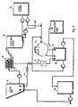
- Fig. 3 illustrates a broke system for treating dry broke according to another preferred embodiment of the invention, which system describes the liquid circulation of the process better than the system of Fig. 2.
- white water obtained from tank 52 is presented to be used not only for diluting the thickened and defiberized broke fed from the press 36 by means of a feeding apparatus into the HC-container 38 and stored in HC-consistency, but also for diluting the broke during the defiberizing.
- a fiber-recovery filter 54 preferably a disc filter, where an essential part of solid matter may be removed from the water so that clear filtrate from reservoir 56 is used for diluting the dry broke.
- Filtrate line 48 coming from the press 36 is provided with a separation device 50 for removing undesired material from the filtrate, after which the cleaned filtrate is guided into reservoir 58 for the turbid filtrate of the fiber-recovery filter 54, which turbid filtrate is returned back to the feed of filter 54.
- the clear filtrate obtained from reservoir 56 is guided into its own reservoir 32, which reservoir provides the defiberizer 10 with dilution liquid.
- the process of Fig. 3 allows for the following two running possibilities. Firstly, it is possible to treat the filtrate of the thickening device 36 with the separation means for the undesired material 50 and the white water filter 54 in every running situation of the defiberizer 10 and the thickening device 36, although, in consideration of possible breaks, the system should be prepared to treat large amounts of liquid quickly with the separation means 50 and the white water filter 54. In principle, this kind of use is not impossible, though, and, accordingly, is not to be excluded from the scope of protection of the invention.
- the second running possibility is to circulate the filtrate of the thickening device through the separation means 50 and the white water filter 54 only when the defiberizer 10 and the thickening device are subjected to a constant load i.e. to evenly running constant-flow broke, as, e.g., in the defiberizing of the trimmings.
- the dimensioning of both the separation means 50 and the white water filter 54 is simple, thanks to constant loads.
- the filtrate of the thickening device may be guided directly through pipeline 44 to the defiberizer 10 without treating with the separation device and the white water filter. Peak loads, during which the filtrate of the thickening device 36 is needed to be guided directly to the defiberizer 10, occur, in addition to web breaks, e.g. in situations when the broke entering the defiberizer is relatively dry, i.e. broke coming from the final stage of paper or paperboard manufacture where the most part of liquid has been removed from the product.
- a further possible method is an arrangement wherein there is a separate separation device for undesired material for treating the filtrate of the thickening device and a treatment apparatus for the filtrate for big loads, i.e. for web breaks or for treating dry broke, so that it would be possible to always clean all the filtrate obtained from the thickening device prior to returning it back to the pulper.
- this kind of arrangement is naturally the most optimal, but naturally it requires investments, compared to the arrangements of Fig. 2 and 3 in which the existing apparatus of the mill is being utilized whenever possible.
- a press as the thickening device, because many modem presses are capable of producing a consistency of the desired 25 - 35 %, and when using appropriate pulp grades and/or applicable presses even a consistency of 45 %, although said consistency range is by no means inevitable.
- a press e.g. a drum press described for instance in FI patents 84397 and 88435 may be utilized.
Landscapes
- Paper (AREA)
- Crystals, And After-Treatments Of Crystals (AREA)
Claims (19)
- Verfahren zur Behandlung von Ausschuss, nach welchem Verfahren von einer Papier-, Karton oder einer ähnlichen Produktionsmaschine stammendes Ausschussmaterial verdünnt, defibriert und eingedickt wird zur Lagerung bei einer hohen Konsistenz, dadurch gekennzeichnet, dass der Ausschuss nach Verdünnung und Defibrierung direkt einer Eindickungsvorrichtung zugeleitet wird, mit der er auf eine hohe Konsistenz eingedickt wird und aus der er in einen Lagerbehälter (38) bei einer Konsistenz von 12-45 % geleitet wird.
- Verfahren nach Patentanspruch 1, dadurch gekennzeichnet, dass das bei der Eindickung anfallende Filtrat zur Defibrierung zurückgeführt wird, um als Verdünnungsflüssigkeit verwendet zu werden.
- Verfahren nach Patentanspruch 1 oder 2, dadurch gekennzeichnet, dass die Eindickung mit einer Presse (36) vorgenommen wird.
- Verfahren nach Patentanspruch 1, 2 oder 3, dadurch gekennzeichnet, dass das bei der Eindickung anfallende Filtrat behandelt wird, um unerwünschtes Material aus dem Filtrat zu entfemen.
- Verfahren nach Patentanspruch 4, dadurch gekennzeichnet, dass das bei der Eindickung anfallende Filtrat mit einer Faserrückgewinnungsvorrichtung behandelt (54) wird.
- Verfahren nach Patentanspruch 5, dadurch gekennzeichnet, dass zumindest Teil der Verdünnungsflüssigkeit bei der Defibrierung Klarfiltrat der Faserrückgewinnungsvorrichtung (54) ist.
- Verfahren nach Patentanspruch 1, 2 oder 3, dadurch gekennzeichnet, dass das bei der Eindickung anfallende Filtrat direkt zur Defibrierung zurückgeleitet wird, um z. B. als Verdünnungsflüssigkeit verwendet zu werden, wenn es gilt, eine maximale Ausschussmenge zu behandeln oder die zur Verdünnung des Ausschusses erforderliche Flüssigkeitsmenge groß ist.
- Verfahren nach Patentanspruch 4, dadurch gekennzeichnet, dass das bei der Eindickung anfallende Filtrat wird behandelt wird, um unerwünschtes Material aus dem Filtrat zu entfemen, wenn Defibrierung und Eindickung bei konstanter Belastung durchgeführt werden.
- Verfahren nach Patentanspruch 5, dadurch gekennzeichnet, dass das Klarfiltrat der Faserrückgewinnungsvorrichtung (54) als Flüssigkeit verwendet wird, die für die Verdünnung bei der Defibrierung eingelagert wird.
- Vorrichtung zur Behandlung von Ausschuss, die sich aus einem oder mehreren Ausschussdefibrator/en (10), wobei es sich um einen Pulper oder ähnliches handeln kann, einer Ausschuss-Eindickungsvorrichtung und einem Ausschuss-Lagerbehälter zusammensetzt, dadurch gekennzeichnet, dass der Defibrator (10) über einen Strömungspfad (33) direkt, ohne Zwischenbehälter, mit einer Eindickungsvorrichtung (36) verbunden ist.
- Vorrichtung nach Patentanspruch 10, dadurch gekennzeichnet, dass die Eindickungsvorrichtung (36) eine Presse ist.
- Vorrichtung nach Patentanspruch 10 oder 11, dadurch gekennzeichnet, dass die Eindickungsvorrichtung (36) mit Mitteln (40) zur Aufnahme des Filtrats versehen ist und dass die Mittel (40) zur Aufnahme des Filtrats über einen Strömungspfad (44) mit dem Defibrator (10) verbunden sind.
- Vorrichtung nach Patentanspruch 12, dadurch gekennzeichnet, dass die Mittel (40) zur Aufnahme des Filtrats über einen Strömungspfad (48) mit Mitteln (50) fürs Entfernen des unerwünschten Materials aus dem Filtrat verbunden sind.
- Vorrichtung nach Patentanspruch 12, dadurch gekennzeichnet, dass die Mittel (40) zur Aufnahme des Filtrats mit der Faserrückgewinnungsvorrichtung verbunden (54) sind.
- Vorrichtung nach Patentanspruch 14, dadurch gekennzeichnet, dass die Mittel (40) zur Aufnahme des Filtrats mit einem Aufbereitungssystem verbunden (58) sind zur Aufbereitung des Trübfiltrats der Faserrückgewinnungsvorrichtung (54).
- Vorrichtung nach Patentanspruch 10, dadurch gekennzeichnet, dass das Aufbereitungs- und Rückführsystem für das Filtrat der Eindickungsvorrichtung (36) eine Faserrückgewinnungsvorrichtung (54) und einen Klarfiltrat-Lagerbehälter (32) sowie die erforderliche Anzahl Pumpen umfasst.
- Vorrichtung nach Patentanspruch 16, dadurch gekennzeichnet, dass das Behandlungs- und Rückführsystem für das Filtrat der Eindickungsvorrichtung (36) des Weiteren Trennmittel (50) für unerwünschtes Material vor der Faserrückgewinnungsvorrichtung (54) umfasst.
- Vorrichtung nach Patentanspruch 10, dadurch gekennzeichnet, dass die Eindickungsvorrichtung (36) mit Mitteln zur Leitung des eingedickten Ausschusses in den HC-Lagerbehälter (38) versehen ist.
- Vorrichtung nach Patentanspruch 10, dadurch gekennzeichnet, dass die Eindickungsvorrichtung (36) notfalls zur Aufbereitung des gesamten Ausstoßes der Produktionsmaschine bemessen ist.
Applications Claiming Priority (2)
| Application Number | Priority Date | Filing Date | Title |
|---|---|---|---|
| FI982512A FI111466B (fi) | 1998-11-20 | 1998-11-20 | Menetelmä ja laitteisto hylkymassan käsittelemiseksi |
| FI982512 | 1998-11-20 |
Publications (2)
| Publication Number | Publication Date |
|---|---|
| EP1010804A1 EP1010804A1 (de) | 2000-06-21 |
| EP1010804B1 true EP1010804B1 (de) | 2004-03-03 |
Family
ID=8552948
Family Applications (1)
| Application Number | Title | Priority Date | Filing Date |
|---|---|---|---|
| EP99123123A Expired - Lifetime EP1010804B1 (de) | 1998-11-20 | 1999-11-19 | Verfahren und Vorrichtung zur Behandlung von Ausschuss |
Country Status (4)
| Country | Link |
|---|---|
| EP (1) | EP1010804B1 (de) |
| AT (1) | ATE261014T1 (de) |
| DE (1) | DE69915227T2 (de) |
| FI (1) | FI111466B (de) |
Families Citing this family (2)
| Publication number | Priority date | Publication date | Assignee | Title |
|---|---|---|---|---|
| DE102016125303B4 (de) | 2016-12-22 | 2018-12-27 | Voith Patent Gmbh | Anlage zur Prozesswasserbehandlung |
| FI130064B (en) * | 2017-12-08 | 2023-01-13 | Kemira Oyj | METHOD FOR PREDICTING OR CONTROLLING MICROSTATICITY IN THE MANUFACTURING PROCESS OF PAPER OR BOARD |
Family Cites Families (1)
| Publication number | Priority date | Publication date | Assignee | Title |
|---|---|---|---|---|
| DE19532301A1 (de) * | 1995-09-01 | 1997-03-06 | Voith Sulzer Stoffaufbereitung | Verfahren zur Aufbereitung von Trockenausschuß einer Papier-, Karton- oder Streichmaschine |
-
1998
- 1998-11-20 FI FI982512A patent/FI111466B/fi not_active IP Right Cessation
-
1999
- 1999-11-19 AT AT99123123T patent/ATE261014T1/de active
- 1999-11-19 DE DE69915227T patent/DE69915227T2/de not_active Expired - Lifetime
- 1999-11-19 EP EP99123123A patent/EP1010804B1/de not_active Expired - Lifetime
Also Published As
| Publication number | Publication date |
|---|---|
| FI982512A0 (fi) | 1998-11-20 |
| EP1010804A1 (de) | 2000-06-21 |
| DE69915227D1 (de) | 2004-04-08 |
| FI982512A7 (fi) | 2000-05-21 |
| ATE261014T1 (de) | 2004-03-15 |
| DE69915227T2 (de) | 2005-02-03 |
| FI111466B (fi) | 2003-07-31 |
Similar Documents
| Publication | Publication Date | Title |
|---|---|---|
| EP0989229B1 (de) | Verfahren zur Eliminierung von klebrigen Verunreinigungen aus aufbereitetem Altpapier enthaltende Papierbreie mittels hydrophobierten Mineralien | |
| US4737238A (en) | Method of processing waste paper with white water and aluminum recycle to papermill | |
| JPH09512063A (ja) | 紙製造における超音波の使用方法 | |
| DE68928632T2 (de) | Verfahren und Vorrichtung zum Behandeln von Faserbrei | |
| DE69407007T2 (de) | Verfahren zur Herstellung von Papier und damit verwendete Vorrichtung | |
| US5112444A (en) | Method for treating pulp | |
| US3067087A (en) | Manufacture of paper of organic hydrophobic fibers | |
| AR010648A1 (es) | Un metodo para fabricar productos sanitarios de papel a partir de periodicos reciclados | |
| EP1010804B1 (de) | Verfahren und Vorrichtung zur Behandlung von Ausschuss | |
| EP0494399B1 (de) | Verfahren zum Führen und Behandeln des Produktionswassers in einer Papierfabrik mit Altpapieraufbereitungsanlage | |
| US2144756A (en) | Process of treating wood pulp to remove pitch | |
| EP1076735B1 (de) | Verfahren und vorrichtung zur behandlung von fasersuspensionen welche mineralien enthalten, wie gestrichenes altpapier, bei der papierherstellung | |
| US5679221A (en) | Method for aluminum reduction in recycled pulp and paper | |
| KR101110189B1 (ko) | 기계 펄프 제조 방법 및 장치 | |
| CA2275710C (en) | Treatment of bleach plant filtrates with oxygen | |
| EP2443069B1 (de) | Anlage und verfahren zur aufbereitung von prozesswasser mit getrennter abtrennung von gasen und feststoff | |
| DE102006012835B3 (de) | Verfahren zur Behandlung von störende Gefäßzellen enthaltendem Zellstoff | |
| WO1998033972A1 (en) | Feeding of washing liquid in a pulp washer | |
| WO1996009433A1 (en) | Paper pulp washing method | |
| EP2039828B1 (de) | Verfahren zur Behandlung einer Papierfasersuspension | |
| FI109813B (fi) | Menetelmä ja laitteisto mineraalipitoisen materiaalin käsittelyyn paperin valmistuksessa | |
| CA2186321C (en) | Method for aluminum reduction in recycled pulp and paper | |
| GB2641002A (en) | An unbleached natural brown copier paper and process thereof | |
| JPH06287880A (ja) | 新聞古紙パルプのピッチコントロ−ル方法 | |
| Mounteer et al. | Effluent minimization in a Lo-solids® bleached eucalyptus kraft pulp mill |
Legal Events
| Date | Code | Title | Description |
|---|---|---|---|
| PUAI | Public reference made under article 153(3) epc to a published international application that has entered the european phase |
Free format text: ORIGINAL CODE: 0009012 |
|
| AK | Designated contracting states |
Kind code of ref document: A1 Designated state(s): AT DE FR IT SE |
|
| AX | Request for extension of the european patent |
Free format text: AL;LT;LV;MK;RO;SI |
|
| RAP1 | Party data changed (applicant data changed or rights of an application transferred) |
Owner name: ANDRITZ-AHLSTROM OY |
|
| AKX | Designation fees paid |
Free format text: AT DE FR IT SE |
|
| 17P | Request for examination filed |
Effective date: 19991125 |
|
| RAP1 | Party data changed (applicant data changed or rights of an application transferred) |
Owner name: ANDRITZ OY |
|
| 17Q | First examination report despatched |
Effective date: 20030123 |
|
| GRAP | Despatch of communication of intention to grant a patent |
Free format text: ORIGINAL CODE: EPIDOSNIGR1 |
|
| GRAS | Grant fee paid |
Free format text: ORIGINAL CODE: EPIDOSNIGR3 |
|
| RIN1 | Information on inventor provided before grant (corrected) |
Inventor name: RAHKONEN, RIITA Inventor name: LUUKKANEN, MATTI Inventor name: HEISKANEN, PASI |
|
| GRAA | (expected) grant |
Free format text: ORIGINAL CODE: 0009210 |
|
| AK | Designated contracting states |
Kind code of ref document: B1 Designated state(s): AT DE FR IT SE |
|
| REF | Corresponds to: |
Ref document number: 69915227 Country of ref document: DE Date of ref document: 20040408 Kind code of ref document: P |
|
| REG | Reference to a national code |
Ref country code: SE Ref legal event code: TRGR |
|
| ET | Fr: translation filed | ||
| PLBE | No opposition filed within time limit |
Free format text: ORIGINAL CODE: 0009261 |
|
| STAA | Information on the status of an ep patent application or granted ep patent |
Free format text: STATUS: NO OPPOSITION FILED WITHIN TIME LIMIT |
|
| 26N | No opposition filed |
Effective date: 20041206 |
|
| PGFP | Annual fee paid to national office [announced via postgrant information from national office to epo] |
Ref country code: SE Payment date: 20141119 Year of fee payment: 16 Ref country code: FR Payment date: 20141119 Year of fee payment: 16 Ref country code: DE Payment date: 20141119 Year of fee payment: 16 |
|
| PGFP | Annual fee paid to national office [announced via postgrant information from national office to epo] |
Ref country code: AT Payment date: 20141120 Year of fee payment: 16 |
|
| PGFP | Annual fee paid to national office [announced via postgrant information from national office to epo] |
Ref country code: IT Payment date: 20141126 Year of fee payment: 16 |
|
| REG | Reference to a national code |
Ref country code: DE Ref legal event code: R119 Ref document number: 69915227 Country of ref document: DE |
|
| REG | Reference to a national code |
Ref country code: AT Ref legal event code: MM01 Ref document number: 261014 Country of ref document: AT Kind code of ref document: T Effective date: 20151119 |
|
| PG25 | Lapsed in a contracting state [announced via postgrant information from national office to epo] |
Ref country code: IT Free format text: LAPSE BECAUSE OF NON-PAYMENT OF DUE FEES Effective date: 20151119 |
|
| REG | Reference to a national code |
Ref country code: FR Ref legal event code: ST Effective date: 20160729 |
|
| PG25 | Lapsed in a contracting state [announced via postgrant information from national office to epo] |
Ref country code: AT Free format text: LAPSE BECAUSE OF NON-PAYMENT OF DUE FEES Effective date: 20151119 Ref country code: SE Free format text: LAPSE BECAUSE OF NON-PAYMENT OF DUE FEES Effective date: 20151120 |
|
| PG25 | Lapsed in a contracting state [announced via postgrant information from national office to epo] |
Ref country code: DE Free format text: LAPSE BECAUSE OF NON-PAYMENT OF DUE FEES Effective date: 20160601 |
|
| PG25 | Lapsed in a contracting state [announced via postgrant information from national office to epo] |
Ref country code: FR Free format text: LAPSE BECAUSE OF NON-PAYMENT OF DUE FEES Effective date: 20151130 |