EP1009886B1 - Unterwasserpflug - Google Patents
Unterwasserpflug Download PDFInfo
- Publication number
- EP1009886B1 EP1009886B1 EP98940383A EP98940383A EP1009886B1 EP 1009886 B1 EP1009886 B1 EP 1009886B1 EP 98940383 A EP98940383 A EP 98940383A EP 98940383 A EP98940383 A EP 98940383A EP 1009886 B1 EP1009886 B1 EP 1009886B1
- Authority
- EP
- European Patent Office
- Prior art keywords
- plough
- share
- leg
- cutting edge
- trench
- Prior art date
- Legal status (The legal status is an assumption and is not a legal conclusion. Google has not performed a legal analysis and makes no representation as to the accuracy of the status listed.)
- Expired - Lifetime
Links
Images


Classifications
-
- H—ELECTRICITY
- H02—GENERATION; CONVERSION OR DISTRIBUTION OF ELECTRIC POWER
- H02G—INSTALLATION OF ELECTRIC CABLES OR LINES, OR OF COMBINED OPTICAL AND ELECTRIC CABLES OR LINES
- H02G1/00—Methods or apparatus specially adapted for installing, maintaining, repairing or dismantling electric cables or lines
- H02G1/06—Methods or apparatus specially adapted for installing, maintaining, repairing or dismantling electric cables or lines for laying cables, e.g. laying apparatus on vehicle
-
- E—FIXED CONSTRUCTIONS
- E02—HYDRAULIC ENGINEERING; FOUNDATIONS; SOIL SHIFTING
- E02F—DREDGING; SOIL-SHIFTING
- E02F5/00—Dredgers or soil-shifting machines for special purposes
- E02F5/02—Dredgers or soil-shifting machines for special purposes for digging trenches or ditches
- E02F5/10—Dredgers or soil-shifting machines for special purposes for digging trenches or ditches with arrangements for reinforcing trenches or ditches; with arrangements for making or assembling conduits or for laying conduits or cables
- E02F5/102—Dredgers or soil-shifting machines for special purposes for digging trenches or ditches with arrangements for reinforcing trenches or ditches; with arrangements for making or assembling conduits or for laying conduits or cables operatively associated with mole-ploughs, coulters
-
- E—FIXED CONSTRUCTIONS
- E02—HYDRAULIC ENGINEERING; FOUNDATIONS; SOIL SHIFTING
- E02F—DREDGING; SOIL-SHIFTING
- E02F5/00—Dredgers or soil-shifting machines for special purposes
- E02F5/02—Dredgers or soil-shifting machines for special purposes for digging trenches or ditches
- E02F5/10—Dredgers or soil-shifting machines for special purposes for digging trenches or ditches with arrangements for reinforcing trenches or ditches; with arrangements for making or assembling conduits or for laying conduits or cables
- E02F5/104—Dredgers or soil-shifting machines for special purposes for digging trenches or ditches with arrangements for reinforcing trenches or ditches; with arrangements for making or assembling conduits or for laying conduits or cables for burying conduits or cables in trenches under water
- E02F5/106—Dredgers or soil-shifting machines for special purposes for digging trenches or ditches with arrangements for reinforcing trenches or ditches; with arrangements for making or assembling conduits or for laying conduits or cables for burying conduits or cables in trenches under water using ploughs, coulters, rippers
-
- H—ELECTRICITY
- H02—GENERATION; CONVERSION OR DISTRIBUTION OF ELECTRIC POWER
- H02G—INSTALLATION OF ELECTRIC CABLES OR LINES, OR OF COMBINED OPTICAL AND ELECTRIC CABLES OR LINES
- H02G1/00—Methods or apparatus specially adapted for installing, maintaining, repairing or dismantling electric cables or lines
- H02G1/06—Methods or apparatus specially adapted for installing, maintaining, repairing or dismantling electric cables or lines for laying cables, e.g. laying apparatus on vehicle
- H02G1/10—Methods or apparatus specially adapted for installing, maintaining, repairing or dismantling electric cables or lines for laying cables, e.g. laying apparatus on vehicle in or under water
Definitions
- the present invention relates to submarine ploughs, and relates particularly, but not exclusively, to submarine ploughs for laying cables and other flexible products under the surface of the sea bed.
- a substantial part of the world's international telecommunications is transmitted by means of fibre optic cables laid on the sea bed.
- a single such cable can carry a very large number of simultaneous telephone calls, and any damage sustained by such cables can result in considerable financial loss.
- One of the main causes of damage to cables laid on the sea bed is fishing activities, and attempts are generally made to protect cables from such interference by burying them under the surface of the sea bed.
- the cables are generally buried by means of a submarine plough, which is towed behind a cable laying ship and picks up a cable, laid on the sea bed, into the plough and then buries it in a trench dug in the surface of the sea bed by the plough.
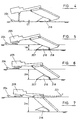
- a conventional plough for burying a cable to a depth of up to one metre in strong or hard soil is shown in Figure 1 and comprises a plough share 1 which comprises an assembly of parts which cut and move the soil at the deepest part of a trench in the sea bed to bury a cable 2 which passes through the plough and is held down by a movable depressor 3.
- the plough share 1 is connected to a pair of depth control skids 4 at the front of the plough by means of a leg 17 and a long beam 5, the skids 4 being movable up or down relative to the beam 5 by moving skid support arms 6.
- the cable plough runs at a generally constant depth by means of the long beam principle, which will be well known to persons skilled in the art.
- a cutting edge 7 of the plough share 1 cuts a flat bottom to the trench in the seabed
- a heel 8 supports the weight of the rear of the plough and slides along the soil surface cut by the cutting edge 7.
- Any tendency of the plough to alter the running depth for example by means of the rear of the plough lifting up by pivoting about the front skids 4, is counteracted by the heel 8 lifting off the soil surface which in turn throws the weight of the rear of the plough on to the share 1 which is unable to support this additional load.
- the plough tends to run deeper, counteracting the movement of the rear of the plough.
- the plough is pulled by means of a tow rope 9 attached to a cable ship.
- the cable 2 enters the plough via a bellmouth device 10 designed to prevent the cable from being bent around radii which are too small (a typical minimum radius being of the order of 1.5 metres).
- a bellmouth device 10 designed to prevent the cable from being bent around radii which are too small (a typical minimum radius being of the order of 1.5 metres).
- If the cable 2 being laid is long it may have one or more joints or repeater amplifiers 11 at intervals along its length and which also have to pass through the plough and be buried with the cable 2.
- An auxiliary repeater burial share 12 which makes the cable trench wider, is used to provide the necessary space for the repeater units 11.
- cable ploughs in weak soils, certain aggressive types of fishing gear can penetrate the sea bed to depth in excess of one metre, which exposes buried cables to the risk of damage. It is therefore desirable for cable ploughs to be able to bury cables deeper than one metre, for example up to three metres deep in weak soils such as soft muds. However, cable plough of this type, when operated in stronger soils, should also be capable of adjusting their ploughing depth to a shallower value to match the pulling force available from the cable laying ship.
- Figure 2 in which parts common to the embodiment of Figure 1 are denoted by like reference numerals but increased by 100, denotes a conventional cable laying plough adapted to address this problem.
- the plough is intended to operate as deeply as possible using the 50 tonne pulling force required by a standard cable plough such that its maximum operating depth is not less than 3 metres in a weak soil such as soft mud.
- the plough of Figure 2 is also intended to be not significantly larger or heavier than the existing plough of Figure 1.
- the plough of Figure 2 consists of the plough of Figure 1, modified to have a longer plough leg 117 and front skid arms 106 to enable the plough to reach greater depths.
- the plough of Figure 2 has serious operational limitations which arise from the fact that the separation distance 113 between the horizontal components of the tow rope force 109 and the soil reaction 114 acting on the share 101 is very large. This is particularly so when the cable plough is digging a shallow trench in strong or hard soil, for example as shown in Figure 2.
- the product of the forces 109, 114 with the separation distance 113 constitutes a couple which tends to lift the rear of the cable plough off the supporting trench surface, thus hampering penetration by the share 101.
- any slack in cable 102 can cause it to bend backwards on itself as shown at 115, which can cause the cable to wrap around the very small radius formed by the lower lip of the bellmouth 110. This can result in severe damage to the cable.
- US-A-4011727 discloses a moveable cable plough in which a plough is pivotably secured to moveable arms on a main body.
- the depth at which the plough cuts a trench in the seabed is varied by raising or lowering the plough by means of hydraulic cylinders, whilst at the same time the angular orientation of the plough is maintained by means of hydraulic cylinders.
- Preferred embodiments of the present invention seek to overcome the above disadvantages of the prior art.
- a submarine plough comprising:
- the plough beam is rigidly attached to the plough leg, the plough share is pivotably connected adjacent a rearward portion thereof to the plough leg, and the plough is adapted to receive an elongate flexible product adjacent a forward end of the plough beam and pass the product along a rear portion of the plough leg into the trench.
- the plough share may comprise a substantially part-cylindrical surface substantially coaxial with the pivot axis of said plough share about the plough leg, and adapted to slide against a cooperating substantially part-cylindrical surface on the plough leg.
- the plough share preferably comprises a pair of substantially parallel arms extending rearwardly of the share and adapted to pivotably receive a cooperating portion of the plough leg therebetween.
- the adjustment means may comprise one or more linear actuators.
- the or each said linear actuator comprises a hydraulic ram.
- the or each said liner actuator includes a respective cross head and a cross pin adapted to slide in one or more arcuate slots in the plough leg, and the or each said cross head is adapted to tightly fit inside the plough share and to cover the corresponding slot at each position of the pin in the slot.
- the plough beam may comprise two beam members connected to said plough leg.
- the plough share leg is preferably connected to the beam members by means of a pair of connecting members, at least one of which comprises a removable portion to enable an elongate flexible product to be mounted to the plough.
- the plough share comprises an elongate plough leg to which said cutting edge and said heel portion are rigidly connected, and wherein the plough leg is pivotably connected adjacent an upper portion thereof to said plough beam.
- the elongate flexible product may be a telecommunications cable.
- the plough preferably further comprises a bellmouth device for receiving the elongate flexible product adjacent a forward end of the plough beam.
- the sea floor engaging means comprises one or more skids connected to the plough beam by means of a respective adjustable arm.
- the plough may further comprise additional sea floor engaging means arranged rearwardly of the sea floor engaging means.
- said additional sea floor engaging means comprises one or more skids connected to a rearward portion of the plough beam.
- This provides the advantage of providing additional support to prevent the plough from sinking into soft mud.
- the adjustment means may further comprise indicator means for indicating the orientation of the plough share relative to the plough beam.
- the plough preferably further comprises a pair of flaps located rearwardly of the plough beam, said flaps being displaceable to allow the passage through the plough of wider portions of the elongate flexible product.
- a submarine plough of a first embodiment of the present invention comprises a share 216 which is pivotably mounted to a plough leg 217 about a pivot 218 which is located as low down and as far back as practicable from a share cutting edge 207.
- the plough leg 217 is rigidly mounted to a plough beam 205, as will be described in further detail with reference to Figure 9.
- the orientation of the share 216 relative to the plough leg 217 is controlled by one or more hydraulic rams 219 provided with a position sensing device (not shown) so that the attitude of the share cutting edge 207 relative to the plough leg 217 is known.
- a position sensing device not shown
- the rotatable share 216 provides depth adjustment of the cutting edge 207 over a range of about 1 metre, and the depth control function of the plough is supplemented by means of the front skids 204 which operate in a similar manner to the skids 4, 104 of the conventional ploughs described with reference to Figures 1 and 2.
- the depth range of the plough from O to 1 metre is adjusted by setting the movable share 216 as shallowly as possible and raising or lowering the front skids 204. It can therefore be seen that at an operating depth of 1 metre, the front of the plough beam 205 is located closer to the surface of the sea bed than in the case of the prior art, thus reducing the possibility of the cable (not shown) bending backwards on itself and sustaining damage.
- the plough can sink to the position shown in Figure 7, and additional support for the rear of the plough is provided by means of auxiliary skids 221 (shown by dotted lines in Figure 7) extending from the rear of the plough beam 205 and which run on the sea bed surface.
- the share 216 is constructed in the form of a closed hollow box provided with two long arms 222 extending rearwardly of the box.
- the back 223 of the box has a surface forming part of a right circular cylinder coaxial with pivot axis 218 and which slides on a mating arcuate surface 224 provided on the front of the plough leg 217 (as shown in Figure 3).
- the bottom of a plough leg 217 is a closed box having a floor which carries the heel 220.
- hydraulic ram 219 has a cross pin on the end thereof to engage with holes 231 in each side 222 of the adjustable share 216, and ingress of soil into the leg box is minimised by making the rod end of the ram 219 in the form of a solid rectangular bar which is wider than the arcuate slot 225 in which it slides and makes a close fit inside the leg box.
- a pair of flaps 226 is attached to the back of the plough leg 217 and provides a V-shaped guide channel when the flaps 226 are forced open. This enables repeaters 11 on the cable 2 to be accommodated, and the flaps can also be opened to provide extra support surface area when working in very weak or soft soil, since the weight of the rear of the plough would otherwise be difficult to support without providing very large additional support surfaces in the form of auxiliary skids 221.
- Additional strength is provided by forming the beam 205 of two horizontal beam members 227, 228 as shown in Figure 9, and which are interconnected by tie bridges 230 at the front and rear end of the plough.
- the plough leg 217 is bolted on to the beam member 227 and is connected to the other beam member 228 by means of a detachable component 229 which is removable to allow cable 202 to be loaded upwards into the plough as shown in Figure 9.
- a detachable component 229 which is removable to allow cable 202 to be loaded upwards into the plough as shown in Figure 9.
- a submarine plough of a second embodiment of the invention comprises a plough share 316 having a forward edge 307 and heel 308, the forward edge 307 and heel 308 being integrally connected to an elongate plough leg 317.
- the plough leg 317 is pivotably mounted to a chassis beam 305 about a pivot 318 at the upper end of the plough leg 317.
- the orientation of the plough leg 317 relative to the chassis beam 305 is controlled by one or more hydraulic rams 319 connected between a rear part 340 of the upper portion of the share leg 317 and a projection 341 at the upper rear part of the chassis beam 305.
- the hydraulic ram 319 is provided with a position sensing device (not shown) so that the attitude of the share cutting edge 307 relative to the chassis beam 305 is known. Accordingly, when the plough leg 317 is pivoted in the direction of arrow A in Figure 10 relative to the chassis beam 305, heel 308 no longer runs on the surface cut by the cutting edge 307, and the cable plough will dig deeper by rotating about front skids 304 until the heel 308 again comes into contact with the bottom of the trench.
- FIG. 10 also differs from that of Figure 3 in that rear stabiliser skids 321 are pivoted to a position on the chassis beam 305 slightly behind the front skids 304, as opposed to a location at the rear of the plough beam 205 in the embodiment of Figure 3.
Landscapes
- Engineering & Computer Science (AREA)
- Mechanical Engineering (AREA)
- Mining & Mineral Resources (AREA)
- Civil Engineering (AREA)
- General Engineering & Computer Science (AREA)
- Structural Engineering (AREA)
- Laying Of Electric Cables Or Lines Outside (AREA)
- Electric Cable Installation (AREA)
- Soil Working Implements (AREA)
Claims (16)
- Unterwasserpflug, der Pflug aufweisend:gekennzeichnet durcheine Pflugschar mit einer Schneidkante, um eine Bodenfurche in den Meeresgrund zu schneiden,einen Pflugbalken mit einem Befestigungsbereich, um Schleppmittel zum Ziehen des Pfluges daran befestigen zu können, um eine Furche in den Meeresgrund zu schneiden, wobei die Pflugschar relativ zum Pflugbalken schwenkbar ist, um den vertikalen Abstand beim Betrieb zwischen der Schneidkante und dem Befestigungsbereich einzustellen, undEinstellmittel, um die Pflugschar relativ zum Pflugbalken zu schwenken,ein Endstück, das hinter der Schneidkante zum Eingreifen in die Bodenfurche angeordnet ist, um den Pflug wenigstens teilweise aufzulagern, undMittel zum Eingreifen in den Meeresgrund, die benachbart zu einem vorderen Ende des Pflugbalkens angeordnet und mit dem Pflugbalken mittels wenigstens eines einstellbaren Arms verbunden sind,wobei der Pflug so gebildet ist, daß ein längliches elastisches Objekt in einer gebogenen Bahn durch ihn hindurch in die Furche hinter der Schneidkante und dem Absatzteil eingeführt werden kann.
- Pflug nach Anspruch 1, bei dem der Pflugbalken starr an einem Pflugschenkel befestigt ist, die Pflugschar nahe einem hinteren Bereich davon schwenkbar am Pflugschenkel befestigt ist, und der Pflug so gebildet ist, daß er ein längliches elastisches Objekt benachbart zu einem vorderen Ende des Pflugbalkens aufnehmen und das Objekt entlang eines hinteren Bereichs des Pflugschenkels in die Furche einführen kann.
- Pflug nach Anspruch 2, bei dem die Pflugschar eine im wesentlichen teilweise zylindrische Fläche aufweist, die zur Schwenkachse der Pflugschar um den Pflugschenkel im wesentlichen koaxial ist, und an einer entsprechenden, im wesentlichen teilweise zylindrischen Fläche am Pflugschenkel gleiten kann.
- Pflug nach Anspruch 2 oder 3, bei dem die Pflugschar zwei im wesentlichen parallele Arme aufweist, die sich hinter der Schar erstrecken, und einen entsprechenden Teil des Pflugschenkels dazwischen schwenkbar aufnehmen können.
- Pflug nach einem der vorhergehenden Ansprüche, bei dem die Einstellmittel ein oder mehrere lineare Stellglieder aufweisen.
- Pflug nach Anspruch 5, bei dem das oder jedes lineare Stellglied eine hydraulische Kolbenstange aufweist.
- Pflug nach Anspruch 5 oder 6, bei dem das oder jedes lineare Stellglied jeweils einen Kreuzkopf und einen Kreuzzapfen umfasst, der in einem oder mehreren gebogenen Schlitzen im Pflugschenkel gleiten kann, wobei der oder jeder Kreuzkopf fest im Pflugschar eingesetzt werden und den entsprechenden Schlitz in jeder Position des Zapfens im Schlitz abdecken kann.
- Pflug nach einem der Ansprüche 2 bis 4, bei dem der Pflugbalken zwei Balkenteile umfasst, die am Pflugschenkel befestigt sind.
- Pflug nach Anspruch 8, bei dem der Pflugschenkel mit den Balkenteilen durch zwei Verbindungselmente verbunden ist, von denen wenigstens eines einen abnehmbaren Bereich aufweist, um ein längliches elastisches Objekt am Pflug befestigen zu können.
- Pflug nach Anspruch 1, bei dem die Pflugschar einen länglichen Pflugschenkel aufweist, an dem die Schneidkante und das Absatzteil starr befestigt sind, und bei dem der Pflugschenkel benachbart zu dessen oberen Bereich mit dem Pflugbalken schwenkbar verbunden ist.
- Pflug nach einem der vorhergehenden Ansprüche, bei dem das längliche elastische Objekt ein Telekommunikationskabel ist.
- Pflug nach einem der vorhergehenden Ansprüche, weiterhin aufweisend eine trichterförmige Vorrichtung zum Aufnehmen eines länglichen elastischen Produkts benachbart zu einem vorderen Ende des Pflugbalkens.
- Pflug nach einem der vorhergehenden Ansprüche, weiterhin aufweisend zusätzliche Mittel zum Eingreifen in den Meeresgrund, die hinter den Mitteln zum Eingreifen in den Meeresgrund angeordnet sind.
- Pflug nach Anspruch 13, bei dem die zusätzlichen Mittel zum Eingreifen in den Meeresgrund eine oder mehrere Gleitschienen aufweisen, die an einem hinteren Abschnitt des Pflugbalkens befestigt sind.
- Pflug nach einem der vorhergehenden Ansprüche, bei dem die Einstellmittel weiterhin Anzeigemittel zum Anzeigen der Ausrichtung der Pflugschar relativ zum Pflugbalken aufweisen.
- Pflug nach einem der vorhergehenden Ansprüche, weiterhin aufweisend zwei Klappen, die hinter dem Pflugbalken angeordnet sind, wobei die Klappen verschiebbar sind, um das Durchführen von breiteren Abschnitten des länglichen elastischen Objekt durch den Pflug zu ermöglichen.
Applications Claiming Priority (5)
| Application Number | Priority Date | Filing Date | Title |
|---|---|---|---|
| GB9718830 | 1997-09-05 | ||
| GBGB9718830.4A GB9718830D0 (en) | 1997-09-05 | 1997-09-05 | Submarine plough |
| GB9724903A GB2329201A (en) | 1997-09-05 | 1997-11-26 | Submarine plough |
| GB9724903 | 1997-11-26 | ||
| PCT/GB1998/002555 WO1999013171A1 (en) | 1997-09-05 | 1998-08-25 | Submarine plough |
Publications (2)
| Publication Number | Publication Date |
|---|---|
| EP1009886A1 EP1009886A1 (de) | 2000-06-21 |
| EP1009886B1 true EP1009886B1 (de) | 2002-04-10 |
Family
ID=26312185
Family Applications (1)
| Application Number | Title | Priority Date | Filing Date |
|---|---|---|---|
| EP98940383A Expired - Lifetime EP1009886B1 (de) | 1997-09-05 | 1998-08-25 | Unterwasserpflug |
Country Status (7)
| Country | Link |
|---|---|
| US (1) | US6435772B1 (de) |
| EP (1) | EP1009886B1 (de) |
| JP (1) | JP2001515977A (de) |
| AU (1) | AU8872098A (de) |
| DE (1) | DE69804815D1 (de) |
| NO (1) | NO20001108L (de) |
| WO (1) | WO1999013171A1 (de) |
Families Citing this family (11)
| Publication number | Priority date | Publication date | Assignee | Title |
|---|---|---|---|---|
| GB9922247D0 (en) * | 1999-09-21 | 1999-11-17 | Engineering Business Ltd | Improvements to submarine ploughs |
| GB0123658D0 (en) * | 2001-10-02 | 2001-11-21 | Global Marine Systems Ltd | Cable or pipe retrieval and burial apparatus and methods |
| ITMI20092044A1 (it) * | 2009-11-20 | 2011-05-21 | Saipem Spa | Metodo e gruppo di scavo per disporre una tubazione in un letto di un corpo d'acqua |
| US9422690B2 (en) | 2012-11-30 | 2016-08-23 | Michael W. N. Wilson | Method and apparatus for performing burial assessment surveys |
| US10323383B2 (en) | 2012-11-30 | 2019-06-18 | Oceaneering International, Inc. | Seabed plow capable of over-the-stern release and retrieval in any of boulder clearing, trenching and backfill configurations |
| US9562343B2 (en) * | 2013-10-16 | 2017-02-07 | Philip Paull | Cable-laying plow attachment for a backhoe and method for using the same |
| GB2545925B (en) | 2015-12-31 | 2021-11-17 | Osbit Ltd | Subsea plough and ploughing |
| EP3216925A1 (de) * | 2016-03-08 | 2017-09-13 | Soil Machine Dynamics Limited | Verfahren und vorrichtung zur herstellung eines grabens in einem gewässergrund |
| CN106436801B (zh) * | 2016-09-20 | 2017-08-08 | 重庆交通大学 | 水域缠绕物清除装置及方法 |
| CN109577406A (zh) * | 2018-12-13 | 2019-04-05 | 国网山东省电力公司电力科学研究院 | 海底无沟式电缆埋设装置及其使用方法 |
| NL2030849B1 (en) * | 2022-02-08 | 2023-09-07 | Royal Ihc Ltd | Underwater plough and method of operating an underwater plough |
Family Cites Families (20)
| Publication number | Priority date | Publication date | Assignee | Title |
|---|---|---|---|---|
| DE727746C (de) * | 1939-08-12 | 1942-11-11 | Aeg | Kabeleinspuelgeraet |
| FR1156475A (fr) * | 1956-07-20 | 1958-05-16 | Machine à poser des tuyaux ou câbles souples en tranchée | |
| US3423946A (en) * | 1967-06-07 | 1969-01-28 | Bell Telephone Labor Inc | Undersea repeater burying plowshare |
| US3824798A (en) * | 1971-11-15 | 1974-07-23 | Furukawa Co Ltd | Submarine cable-burying devices |
| JPS5247559B2 (de) * | 1972-06-07 | 1977-12-03 | ||
| NL7306461A (de) | 1973-05-09 | 1974-11-12 | ||
| GB1498242A (en) * | 1974-07-26 | 1978-01-18 | Sumitomo Electric Industries | Movable cable plow for burying underwater cable |
| GB1493346A (en) * | 1974-12-03 | 1977-11-30 | Ede A | Soil blade implement |
| GB2027771B (en) | 1978-07-29 | 1982-06-30 | Higgs P | Deep vertical trench plough |
| DE2922410C2 (de) * | 1979-06-01 | 1985-01-24 | Hydro-Jet-System Establishment, Vaduz | Verfahren und Vorrichtung zum Einbetten von Kabeln und dergleichen in einen Gewässergrund |
| US4410297A (en) * | 1981-01-19 | 1983-10-18 | Lynch Robert P | Marine continuous pipe laying system |
| GB8301514D0 (en) * | 1983-01-20 | 1983-02-23 | British Petroleum Co Plc | Plough assembly |
| EP0185422B1 (de) * | 1984-12-19 | 1990-02-07 | Soil Machine Dynamics Limited | Verfahren und Vorrichtung zum Ausheben von Boden |
| GB8524410D0 (en) * | 1985-10-03 | 1985-11-06 | Soil Machine Dynamics Ltd | Pipeline/cable plough |
| GB8703154D0 (en) * | 1987-02-11 | 1987-03-18 | Soil Machine Dynamics Ltd | Submarine cable plough |
| GB8714515D0 (en) * | 1987-06-20 | 1987-07-22 | Land & Marine Eng Ltd | Seabed trenching apparatus |
| DE3739041A1 (de) * | 1987-11-17 | 1989-05-24 | Siemens Ag | Kabelpflug |
| JPH01264511A (ja) * | 1988-04-11 | 1989-10-20 | Nippon Telegr & Teleph Corp <Ntt> | 海底ケーブル埋設装置 |
| GB9618638D0 (en) * | 1996-09-06 | 1996-10-16 | Cable & Wireless Plc | Improvements in underwater ploughing |
| US5988948A (en) * | 1997-09-04 | 1999-11-23 | Cable And Wireless Plc | Underwater plough and method for varying ploughing depth |
-
1998
- 1998-08-25 JP JP2000510942A patent/JP2001515977A/ja active Pending
- 1998-08-25 DE DE69804815T patent/DE69804815D1/de not_active Expired - Lifetime
- 1998-08-25 AU AU88720/98A patent/AU8872098A/en not_active Abandoned
- 1998-08-25 EP EP98940383A patent/EP1009886B1/de not_active Expired - Lifetime
- 1998-08-25 WO PCT/GB1998/002555 patent/WO1999013171A1/en active IP Right Grant
-
2000
- 2000-03-03 NO NO20001108A patent/NO20001108L/no not_active Application Discontinuation
- 2000-03-03 US US09/518,422 patent/US6435772B1/en not_active Expired - Lifetime
Also Published As
| Publication number | Publication date |
|---|---|
| EP1009886A1 (de) | 2000-06-21 |
| US20020071724A1 (en) | 2002-06-13 |
| NO20001108L (no) | 2000-04-18 |
| US6435772B1 (en) | 2002-08-20 |
| AU8872098A (en) | 1999-03-29 |
| NO20001108D0 (no) | 2000-03-03 |
| JP2001515977A (ja) | 2001-09-25 |
| DE69804815D1 (de) | 2002-05-16 |
| WO1999013171A1 (en) | 1999-03-18 |
Similar Documents
| Publication | Publication Date | Title |
|---|---|---|
| EP1009886B1 (de) | Unterwasserpflug | |
| CA3017056C (en) | Method and apparatus for forming a trench in a sea floor | |
| CA1331101C (en) | Cable plough | |
| US6837653B1 (en) | Ploughs | |
| US4664553A (en) | Plough assembly | |
| EP1432877B1 (de) | Vorrichtung und verfahren zum eingraben und einholen von kabeln oder rohren | |
| EP2840187A1 (de) | Verfahren und Vorrichtung zur Herstellung eines Grabens in einem Gewässergrund | |
| GB2364358A (en) | Plough for laying elongate articles | |
| GB2285821A (en) | Trenching plough | |
| GB2329201A (en) | Submarine plough | |
| EP0296783B1 (de) | Vorrichtung zum Ausheben von Meeresboden | |
| US5988948A (en) | Underwater plough and method for varying ploughing depth | |
| US20220074166A1 (en) | Subsea plough for burying a flexible elongate member | |
| EP0828031B1 (de) | Vorrichtung zum Pflügen unter Wasser | |
| EP0010915B1 (de) | Pflug für Gräben | |
| GB2357134A (en) | A cable or pipe laying plough | |
| WO2001075236A1 (en) | Submarine plough | |
| NL2030849B1 (en) | Underwater plough and method of operating an underwater plough | |
| EP4112821A2 (de) | Vorrichtung zum einführen eines länglichen objekts in einen graben | |
| WO2001049946A1 (en) | Submarine plough | |
| CA2515897C (en) | Underground cable or conduit installing apparatus and method | |
| GB2062064A (en) | Ditching Machine | |
| WO2000071822A1 (en) | Submarine plough |
Legal Events
| Date | Code | Title | Description |
|---|---|---|---|
| PUAI | Public reference made under article 153(3) epc to a published international application that has entered the european phase |
Free format text: ORIGINAL CODE: 0009012 |
|
| 17P | Request for examination filed |
Effective date: 20000228 |
|
| AK | Designated contracting states |
Kind code of ref document: A1 Designated state(s): DE ES FR GB IT NL |
|
| 17Q | First examination report despatched |
Effective date: 20000821 |
|
| GRAG | Despatch of communication of intention to grant |
Free format text: ORIGINAL CODE: EPIDOS AGRA |
|
| GRAG | Despatch of communication of intention to grant |
Free format text: ORIGINAL CODE: EPIDOS AGRA |
|
| GRAH | Despatch of communication of intention to grant a patent |
Free format text: ORIGINAL CODE: EPIDOS IGRA |
|
| GRAH | Despatch of communication of intention to grant a patent |
Free format text: ORIGINAL CODE: EPIDOS IGRA |
|
| REG | Reference to a national code |
Ref country code: GB Ref legal event code: IF02 |
|
| GRAA | (expected) grant |
Free format text: ORIGINAL CODE: 0009210 |
|
| AK | Designated contracting states |
Kind code of ref document: B1 Designated state(s): DE ES FR GB IT NL |
|
| PG25 | Lapsed in a contracting state [announced via postgrant information from national office to epo] |
Ref country code: NL Free format text: LAPSE BECAUSE OF FAILURE TO SUBMIT A TRANSLATION OF THE DESCRIPTION OR TO PAY THE FEE WITHIN THE PRESCRIBED TIME-LIMIT Effective date: 20020410 Ref country code: IT Free format text: LAPSE BECAUSE OF FAILURE TO SUBMIT A TRANSLATION OF THE DESCRIPTION OR TO PAY THE FEE WITHIN THE PRE;WARNING: LAPSES OF ITALIAN PATENTS WITH EFFECTIVE DATE BEFORE 2007 MAY HAVE OCCURRED AT ANY TIME BEFORE 2007. THE CORRECT EFFECTIVE DATE MAY BE DIFFERENT FROM THE ONE RECORDED.SCRIBED TIME-LIMIT Effective date: 20020410 Ref country code: FR Free format text: LAPSE BECAUSE OF FAILURE TO SUBMIT A TRANSLATION OF THE DESCRIPTION OR TO PAY THE FEE WITHIN THE PRESCRIBED TIME-LIMIT Effective date: 20020410 |
|
| REF | Corresponds to: |
Ref document number: 69804815 Country of ref document: DE Date of ref document: 20020516 |
|
| PG25 | Lapsed in a contracting state [announced via postgrant information from national office to epo] |
Ref country code: DE Free format text: LAPSE BECAUSE OF FAILURE TO SUBMIT A TRANSLATION OF THE DESCRIPTION OR TO PAY THE FEE WITHIN THE PRESCRIBED TIME-LIMIT Effective date: 20020711 |
|
| NLV1 | Nl: lapsed or annulled due to failure to fulfill the requirements of art. 29p and 29m of the patents act | ||
| PG25 | Lapsed in a contracting state [announced via postgrant information from national office to epo] |
Ref country code: ES Free format text: LAPSE BECAUSE OF FAILURE TO SUBMIT A TRANSLATION OF THE DESCRIPTION OR TO PAY THE FEE WITHIN THE PRESCRIBED TIME-LIMIT Effective date: 20021030 |
|
| EN | Fr: translation not filed | ||
| PLBE | No opposition filed within time limit |
Free format text: ORIGINAL CODE: 0009261 |
|
| STAA | Information on the status of an ep patent application or granted ep patent |
Free format text: STATUS: NO OPPOSITION FILED WITHIN TIME LIMIT |
|
| 26N | No opposition filed |
Effective date: 20030113 |
|
| PGFP | Annual fee paid to national office [announced via postgrant information from national office to epo] |
Ref country code: GB Payment date: 20080820 Year of fee payment: 11 |
|
| GBPC | Gb: european patent ceased through non-payment of renewal fee |
Effective date: 20090825 |
|
| PG25 | Lapsed in a contracting state [announced via postgrant information from national office to epo] |
Ref country code: GB Free format text: LAPSE BECAUSE OF NON-PAYMENT OF DUE FEES Effective date: 20090825 |