EP1009801B1 - Messer für eine vorrichtung zum aufhacken eines treberkuchens - Google Patents
Messer für eine vorrichtung zum aufhacken eines treberkuchens Download PDFInfo
- Publication number
- EP1009801B1 EP1009801B1 EP98952538A EP98952538A EP1009801B1 EP 1009801 B1 EP1009801 B1 EP 1009801B1 EP 98952538 A EP98952538 A EP 98952538A EP 98952538 A EP98952538 A EP 98952538A EP 1009801 B1 EP1009801 B1 EP 1009801B1
- Authority
- EP
- European Patent Office
- Prior art keywords
- chopping
- knife
- knife according
- cutting element
- ploughshare
- Prior art date
- Legal status (The legal status is an assumption and is not a legal conclusion. Google has not performed a legal analysis and makes no representation as to the accuracy of the status listed.)
- Expired - Lifetime
Links
- 238000005520 cutting process Methods 0.000 claims abstract description 40
- 238000004519 manufacturing process Methods 0.000 claims abstract description 7
- 235000013405 beer Nutrition 0.000 claims abstract description 3
- 239000004458 spent grain Substances 0.000 claims description 8
- 238000005266 casting Methods 0.000 claims description 6
- 229910052751 metal Inorganic materials 0.000 claims description 5
- 239000002184 metal Substances 0.000 claims description 5
- 229910000831 Steel Inorganic materials 0.000 claims description 4
- 239000010959 steel Substances 0.000 claims description 4
- 229910001369 Brass Inorganic materials 0.000 claims description 3
- CWYNVVGOOAEACU-UHFFFAOYSA-N Fe2+ Chemical compound [Fe+2] CWYNVVGOOAEACU-UHFFFAOYSA-N 0.000 claims description 3
- 239000010951 brass Substances 0.000 claims description 3
- 230000000295 complement effect Effects 0.000 claims description 2
- 239000010935 stainless steel Substances 0.000 description 6
- 229910001220 stainless steel Inorganic materials 0.000 description 6
- HCHKCACWOHOZIP-UHFFFAOYSA-N Zinc Chemical compound [Zn] HCHKCACWOHOZIP-UHFFFAOYSA-N 0.000 description 5
- 239000011701 zinc Substances 0.000 description 5
- 229910052725 zinc Inorganic materials 0.000 description 5
- PTFCDOFLOPIGGS-UHFFFAOYSA-N Zinc dication Chemical compound [Zn+2] PTFCDOFLOPIGGS-UHFFFAOYSA-N 0.000 description 4
- 238000000034 method Methods 0.000 description 4
- 239000000853 adhesive Substances 0.000 description 3
- 230000001070 adhesive effect Effects 0.000 description 3
- 238000000855 fermentation Methods 0.000 description 2
- 230000004151 fermentation Effects 0.000 description 2
- 238000002386 leaching Methods 0.000 description 2
- 239000002994 raw material Substances 0.000 description 2
- 238000005406 washing Methods 0.000 description 2
- 240000004808 Saccharomyces cerevisiae Species 0.000 description 1
- 235000014680 Saccharomyces cerevisiae Nutrition 0.000 description 1
- 229910001297 Zn alloy Inorganic materials 0.000 description 1
- 229910045601 alloy Inorganic materials 0.000 description 1
- 239000000956 alloy Substances 0.000 description 1
- 238000013124 brewing process Methods 0.000 description 1
- 230000004663 cell proliferation Effects 0.000 description 1
- 238000010276 construction Methods 0.000 description 1
- 230000001419 dependent effect Effects 0.000 description 1
- 238000006073 displacement reaction Methods 0.000 description 1
- 238000010438 heat treatment Methods 0.000 description 1
- 238000003754 machining Methods 0.000 description 1
- 239000000463 material Substances 0.000 description 1
- 150000002739 metals Chemical class 0.000 description 1
- 238000003801 milling Methods 0.000 description 1
- 230000000149 penetrating effect Effects 0.000 description 1
- 238000007670 refining Methods 0.000 description 1
- 239000007787 solid Substances 0.000 description 1
- 239000011573 trace mineral Substances 0.000 description 1
- 235000013619 trace mineral Nutrition 0.000 description 1
- 230000007704 transition Effects 0.000 description 1
- XLYOFNOQVPJJNP-UHFFFAOYSA-N water Substances O XLYOFNOQVPJJNP-UHFFFAOYSA-N 0.000 description 1
Images


Classifications
-
- C—CHEMISTRY; METALLURGY
- C12—BIOCHEMISTRY; BEER; SPIRITS; WINE; VINEGAR; MICROBIOLOGY; ENZYMOLOGY; MUTATION OR GENETIC ENGINEERING
- C12C—BEER; PREPARATION OF BEER BY FERMENTATION; PREPARATION OF MALT FOR MAKING BEER; PREPARATION OF HOPS FOR MAKING BEER
- C12C7/00—Preparation of wort
- C12C7/14—Lautering, i.e. clarifying wort
- C12C7/16—Lautering, i.e. clarifying wort by straining
- C12C7/17—Lautering, i.e. clarifying wort by straining in lautertuns, e.g. in a tub with perforated false bottom
-
- C—CHEMISTRY; METALLURGY
- C12—BIOCHEMISTRY; BEER; SPIRITS; WINE; VINEGAR; MICROBIOLOGY; ENZYMOLOGY; MUTATION OR GENETIC ENGINEERING
- C12C—BEER; PREPARATION OF BEER BY FERMENTATION; PREPARATION OF MALT FOR MAKING BEER; PREPARATION OF HOPS FOR MAKING BEER
- C12C7/00—Preparation of wort
- C12C7/14—Lautering, i.e. clarifying wort
Definitions
- the present invention relates to knives for chopping devices the Marc cake, as used in breweries in the production of Beer is produced. These so-called chopping machines are for a safe, rapid and productive refining process of great importance. While the spent grain is composed of the wort, so that the Flow due to the increased drought resistance accordingly is slowed down. The grains must therefore be loosened to reduce the drought resistance and the wort flow accelerate again. This is intended to be chopped up during the leaching process by improving the contact of the water with the spent grains and leaching quickly and completely by opening new paths enable.
- Such chopping machines are known from the prior art.
- the known devices are preferred for hygienic reasons made of stainless steel. They are on the stainless steel shafts of the knives Cutting elements also made of stainless steel are welded on. in the The result is that the chopping or cutting elements are unsolvable with the Knife shaft connected.
- This one-piece construction of the knives has the disadvantage that the chopping or cutting elements are not replaced independently of the knives can be. However, it is precisely these components that are being cut exposed to a considerable abrasive load. To reach therefore the chopping or cutting elements their wear limit, so must the entire knife can be replaced.
- the shape of the Chopping or cutting elements are subject to constant further development and can be tailored to the raw materials to be processed.
- the chopping machine is now to be installed in an existing brewery during a plant revision with the latest generation of chipping or cutting elements, the complete Knives can be replaced.
- the object of the present invention is therefore to provide knives for a chopping machine to create where the chopping or cutting elements can be replaced regardless of the knife shaft.
- This task is performed by a chopping machine with the characteristics of Claim 1 solved.
- the chopping or cutting elements releasably attached to the shaft of the chopping knife. Is a change of Chopping or cutting elements due to wear or system revision the connection between the chopping or cutting elements is required and the knife shank and new components can be assembled become.
- the chopping or cutting elements can also be used according to the invention an adhesive connection to the shaft.
- the adhesive connection is then broken and glued on a new chopping or cutting element.
- the used Adhesive is to be coordinated so that the connection without Damage to the shaft can be broken.
- the detachable connection can also be designed as a shrink connection his. In order to loosen the parts, heating must then take place in certain areas.
- the Shrink connection has the advantage that there are no fasteners can survive, which worsens the flow on the knife.
- a rivet connection also comes to fix the chopping or cutting elements in question.
- the rivets may need to be removed to change the attachments.
- the cutting elements at the end of the knife shafts come at the loafing core of the grain cake play an outstanding role.
- a particularly good one Loosening of the spent grain is achieved when these cutting elements are in well-known type are designed like plowshares.
- the ploughshare element should be moved over the bottom of the lauter tun an essentially flat or concave surface on the underside exhibit.
- the chopper slides in the lowest position then the ploughshare element with the flat underside with a small one Cut across the bottom of the lauter tun and cut through the top the spent cake with the wedge-shaped cross-sectional profile.
- On The largely edge-free top side does not cause any undesirable displacement of the Marc cake.
- the ploughshare elements act considerable opposing forces. These forces must come from the ploughshare can be derived via the detachable connection in the knife shaft. It is therefore particularly preferable, on the top of the ploughshare elements to provide a groove or a continuous slot, wherein whose cross-section, at least in sections, complementary to the shape Cross section of the knife shaft is designed.
- the ploughshare elements can be pushed onto the knife base with this groove and the the resulting positive connection can be used in conjunction with a further fastener optimally the pressure forces occurring transfer.
- Such attachment of the ploughshare elements on Knife foot can, for example, by screwing in a fixing screw or hammering in a grooved pin.
- Any chopping knife can cut particularly intensively in a manner known per se with a split shaft each have a ploughshare element on both shaft ends. Both ploughshare elements are at the same vertical height to a process enable the chipper to be in the lowest position however horizontally offset. The cut density in the spent cake is significantly increased by this measure.
- the shaft of the chopping knife according to the invention should be in itself be known made of stainless steel. Are particularly suitable thereby flat steels, since only a minimal manufacturing effort is required Manufacture of the knife shaft from this raw material is necessary.
- the loosening of the spent cake depends in particular on the shape of the Ploughshare elements and the horizontal knife.
- the Ploughshare elements can be designed to be particularly streamlined.
- Ploughshare elements with complex ones have been particularly advantageous Freeform surfaces highlighted.
- the production of such free-form surfaces with conventional machining processes is extraordinary expensive because the ploughshare elements made of solid blanks with Multi-axis milling machines must be milled out. That is why preferable, the ploughshare elements and / or the horizontal knives as To produce castings.
- Complex freeform surfaces can be combined in one Casting process can be easily manufactured. Once made In principle, the casting mold can have any number of ploughshare elements getting produced.
- the ploughshare-like elements and / or are particularly cheap make the horizontal knives from a non-ferrous metal, because Nonferrous metals can be processed much better in casting processes are considered to be particularly steel. Because between the attachments and the Knife shank, no weld connection is necessary, as is the case with conventional Roughing knives is required, it is possible to attach parts to be made from a non-ferrous metal with good casting properties.
- the ploughshare elements and the horizontal knives according to the invention made of any hygienic metal , it is particularly preferable to choose these components To manufacture brass or a similar zinc-containing alloy. It this results in the desired washing in of zinc ions, the so that components that are more susceptible to wear can be replaced very easily can be. The rest of the system can continue from the otherwise more preferable stainless steel material.
- Brass MS 58 has proven to be particularly easy to process. The The desired washing in of zinc ions is achieved.
- Fig. 1 the structure of a lauter tun 1 is shown schematically.
- the chopping machine 2 is in the lowest position. If the spent grain cake, not shown, is to be loosened, the chopping machine is driven via the main shaft 3 and set in rotation in the direction indicated by the arrow.
- the knife bars 4 rotate over the spent cake, which is cut by the knives 5.
- knives 5 with a straight shaft are shown on the right side and knives with a zigzag-shaped shaft on the left side.
- the knives each have four horizontal knives 6 on the shaft of the chopping knives and one ploughshare element 7 on the shaft end of the chopping knives.
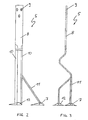
- FIG. 2 shows a first embodiment of a knife 5 according to the invention.
- the knife shaft 8 has three elongated holes 9 with which the knife can be fastened to the knife bar 4.
- Chamfer surfaces 10 are provided in the middle and lower region of the shaft in order to achieve an arrow of the shaft cross section. This arrowing prevents the layers of the spent cake from being pushed undesirably.
- This embodiment of the knife 5 according to the invention has a shaft divided in the lower region with a second shaft end 11. Ploughshare elements 7 are fixed to both ends of the shaft, each with two notch pins 12. 3 shows the zigzag structure of the knife shaft.
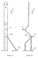
- FIG. 4 and FIG. 5 show a second embodiment of a knife 5 according to the invention.
- This embodiment corresponds to the embodiment shown in FIGS . 2 and 3 , but is expanded by the horizontal knives 6 attached to the side of the shaft.
- the screws 13 for the releasable connection of the horizontal knives are shown only schematically.
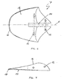
- Fig. 6 shows the ploughshare element 7 in a view from above.
- the ploughshare element is constructed with mirror symmetry with respect to the plane of symmetry E.
- the upper side contains the slot 14, the cross section of which corresponds to the cross section of the shaft end and with which the ploughshare element can be pushed onto the knife base. Grooved pins can be hammered into the two bores 15, each penetrating a recess in the base of the knife shank and thereby fixing the ploughshare element on the base.
- the top 16 of the ploughshare element is designed as a complex free-form surface.
- the underside 17 of the ploughshare element has a flat surface.
- the front edge 18 of the ploughshare element has an edge-free radial transition from the top 16 to the bottom 17 in order to minimize the wear of the ploughshare element in this cutting area.
Landscapes
- Chemical & Material Sciences (AREA)
- Organic Chemistry (AREA)
- Engineering & Computer Science (AREA)
- General Health & Medical Sciences (AREA)
- Food Science & Technology (AREA)
- Biochemistry (AREA)
- Bioinformatics & Cheminformatics (AREA)
- General Engineering & Computer Science (AREA)
- Health & Medical Sciences (AREA)
- Genetics & Genomics (AREA)
- Life Sciences & Earth Sciences (AREA)
- Wood Science & Technology (AREA)
- Zoology (AREA)
- Knives (AREA)
- Heterocyclic Carbon Compounds Containing A Hetero Ring Having Oxygen Or Sulfur (AREA)
- Food-Manufacturing Devices (AREA)
- Manufacturing And Processing Devices For Dough (AREA)
- Formation And Processing Of Food Products (AREA)
Description
- Fig. 1
- einen Läuterbottich in seitlich geschnittener Darstellung;
- Fig. 2
- eine erste Ausführungsform eines erfindungsgemäßen Messers in seitlicher Ansicht;
- Fig. 3
- die Ausführungsform aus Fig. 2 in Ansicht von hinten;
- Fig. 4
- eine zweite Ausführungsform eines erfindungsgemäßen Messers in seitlicher Ansicht;
- Fig. 5
- die Ausführungsform aus Fig. 4 in Ansicht von hinten;
- Fig. 6
- eine Ausführungsform eines Pflugscharelements in Ansicht von oben;
- Fig. 7
- das Pflugscharelement aus Fig. 6 in seitlicher Ansicht;
- Fig. 8
- den Rohling des Pflugscharelements aus Fig. 6 in perspektivischer Ansicht.
Claims (17)
- Messer für eine Vorrichtung zum Aufhacken des bei der Bierherstellung anfallenden Treberkuchens in einem Läuterbottich, wobei das Messer einen geraden, gewellten oder zickzackförmigen, insgesamt im wesentlichen vertikal verlaufenden Schaft aufweist, an dessen Schaftende mindestens ein Hack- oder Schneidelement angeordnet ist,
dadurch gekennzeichnet, daß das Hack- oder Schneidelement (7) lösbar an dem Schaft (5) befestigbar ist. - Messer nach Anspruch 1,
dadurch gekennzeichnet, daß die lösbare Verbindung als Schraubverbindung ausgeführt ist. - Messer nach Anspruch 1,
dadurch gekennzeichnet, daß die lösbare Verbindung als Kerbstiftverbindung ausgeführt ist. - Messer nach Anspruch 1,
dadurch gekennzeichnet, daß die lösbare Verbindung als Klebverbindung ausgeführt ist. - Messer nach Anspruch 1,
dadurch gekennzeichnet, daß die lösbare Verbindung als Nietverbindung ausgeführt ist. - Messer nach Anspruch 1,
dadurch gekennzeichnet, daß die lösbare Verbindung als Schrumpfverbindung ausgeführt ist. - Messer nach einem der Ansprüche 1 bis 4,
dadurch gekennzeichnet, daß das Hack- oder Schneidelement (7) pflugscharähnlich ausgebildet ist, und an der Unterseite eine im wesentlichen ebene oder konkave Oberfläche und im Querschnitt eine im wesentlichen keilförmige Außenkontur aufweist. - Messer nach Anspruch 7,
dadurch gekennzeichnet, daß das pflugscharähnlich ausgebildete Hack- oder Schneideelement (7) bezüglich der senkrechten Ebene, die Pflugscharspitze und Pflugscharende schneidet, spiegelsymmetrisch aufgebaut ist. - Messer nach einem der Ansprüche 7 oder 8,
dadurch gekennzeichnet, daß das pflugscharähnlich ausgebildete Hack- oder Schneideelement (7) eine Nut oder einen Schlitz (14) enthält, wobei der Querschnitt der Nut zumindest abschnittsweise formkomplementär zum Querschnitt des Messerschaftes (5) ausgestaltet ist. - Messer nach Anspruch 9,
dadurch gekennzeichnet, daß das pflugscharähnlich ausgebildete Hack- oder Schneideelement (7) zumindest eine senkrecht zur Nut und parallel zur Unterseite verlaufende Bohrung (15) zur Aufnahme einer Schraube, eines Kerbstifts oder ähnlichem aufweist. - Messer nach Anspruch 9,
dadurch gekennzei chn et,
daß das pflugscharähnlich ausgebildete Hack- oder Schneideelement (7) zumindest eine parallel zur Nut und senkrecht zur Unterseite verlaufende Bohrung zur Aufnahme einer Schraube, eines Kerbstifts oder ähnlichem aufweist. - Messer nach einem der Ansprüche 1 bis 9,
dadurch gekennzeichnet, daß das Messer einen im unteren Bereich geteilten Schaft aufweist, wobei an beiden Schaftenden ein Hack- oder Schneidelement (7, 12) angeordnet ist. - Messer nach einem der Ansprüche 1 bis 10,
dadurch gekennzeichnet, daß im mittleren Bereich des Schaftes im wesentlichen horizontal verlaufende Schneidelemente (6) lösbar befestigbar sind. - Messer nach einem der Ansprüche 1 bis 11,
dadurch gekennzeichnet, daß der Schaft des Messers (5) im wesentlichen aus einem gebogenen Flachstahl, insbesondere aus Edelstahl, hergestellt ist. - Messer nach einem der Ansprüche 1 bis 12,
dadurch gekennzeichnet, daß das Hack- oder Schneidelement (7, 12) ein Gußkörper ist. - Messer nach einem der Ansprüche 1 bis 13,
dadurch gekennzeichnet, daß das Hack- oder Schneidelement (7, 12) aus einem Nichteisenmetall hergestellt ist. - Messer nach einem der Ansprüche 1 bis 14,
dadurch gekennzeichnet, daß das Hack- oder Schneidelement (7, 12) aus Messing, insbesondere aus MS 58, hergestellt ist.
Applications Claiming Priority (3)
| Application Number | Priority Date | Filing Date | Title |
|---|---|---|---|
| DE19738579A DE19738579C2 (de) | 1997-09-04 | 1997-09-04 | Messer für eine Vorrichtung zum Aufhacken eines Treberkuchens |
| DE19738579 | 1997-09-04 | ||
| PCT/DE1998/002592 WO1999011750A2 (de) | 1997-09-04 | 1998-09-03 | Messer für eine vorrichtung zum aufhacken eines treberkuchens |
Publications (2)
| Publication Number | Publication Date |
|---|---|
| EP1009801A2 EP1009801A2 (de) | 2000-06-21 |
| EP1009801B1 true EP1009801B1 (de) | 2004-03-17 |
Family
ID=7841111
Family Applications (1)
| Application Number | Title | Priority Date | Filing Date |
|---|---|---|---|
| EP98952538A Expired - Lifetime EP1009801B1 (de) | 1997-09-04 | 1998-09-03 | Messer für eine vorrichtung zum aufhacken eines treberkuchens |
Country Status (6)
| Country | Link |
|---|---|
| EP (1) | EP1009801B1 (de) |
| AT (1) | ATE262031T1 (de) |
| AU (1) | AU1021699A (de) |
| DE (2) | DE19738579C2 (de) |
| ES (1) | ES2214742T3 (de) |
| WO (1) | WO1999011750A2 (de) |
Family Cites Families (5)
| Publication number | Priority date | Publication date | Assignee | Title |
|---|---|---|---|---|
| DE225329C (de) * | ||||
| DE1048547B (de) * | 1959-01-15 | |||
| GB2062004B (en) * | 1979-10-25 | 1983-05-25 | Balfour & Co Ltd Henry | Lautering apparatus |
| DE3528647C1 (de) * | 1985-08-09 | 1986-08-28 | August 8710 Kitzingen Lenz | Aufhackvorrichtung in Laeuterbottichen zur Wuerzegewinnung bei der Biererzeugung |
| DE29510245U1 (de) * | 1995-06-23 | 1995-08-31 | Anton Steinecker Maschinenfabrik GmbH, 85356 Freising | Aufhackvorrichtung für einen Läuterbottich für die Biererzeugung |
-
1997
- 1997-09-04 DE DE19738579A patent/DE19738579C2/de not_active Expired - Fee Related
-
1998
- 1998-09-03 EP EP98952538A patent/EP1009801B1/de not_active Expired - Lifetime
- 1998-09-03 AT AT98952538T patent/ATE262031T1/de not_active IP Right Cessation
- 1998-09-03 AU AU10216/99A patent/AU1021699A/en not_active Abandoned
- 1998-09-03 DE DE59811012T patent/DE59811012D1/de not_active Expired - Lifetime
- 1998-09-03 WO PCT/DE1998/002592 patent/WO1999011750A2/de not_active Ceased
- 1998-09-03 ES ES98952538T patent/ES2214742T3/es not_active Expired - Lifetime
Also Published As
| Publication number | Publication date |
|---|---|
| ATE262031T1 (de) | 2004-04-15 |
| ES2214742T3 (es) | 2004-09-16 |
| DE19738579C2 (de) | 2000-01-20 |
| DE59811012D1 (de) | 2004-04-22 |
| WO1999011750A2 (de) | 1999-03-11 |
| AU1021699A (en) | 1999-03-22 |
| EP1009801A2 (de) | 2000-06-21 |
| WO1999011750A3 (de) | 1999-05-27 |
| DE19738579A1 (de) | 1999-03-11 |
Similar Documents
| Publication | Publication Date | Title |
|---|---|---|
| EP2593233B1 (de) | Messerträger für zerkleinerungsvorrichtungen | |
| EP2218507B1 (de) | Vorrichtung zum Zerkleinern von Aufgabegut mit Abstreifelementen | |
| DE3800126A1 (de) | Hartmetalleinsaetze und mit denselben versehene schneidwerkzeuge | |
| EP0005726B1 (de) | Schneidsatz für eine Vorrichtung zum Zerkleinern von Nahrungsmitteln | |
| EP3202290A1 (de) | Mahlwerk, mühle, kaffeezubereitungsvorrichtung mit mühle sowie mahlverfahren | |
| DE4340608B4 (de) | Schneidmesser und Verwendung von Schneidmessern zur Erzeugung von Zähnen von Spiralkegelrädern und Hypoid-Zahnrädern oder Ritzeln | |
| DE112008000082T5 (de) | Schneidplatte | |
| DE2254391A1 (de) | Handwerkzeug | |
| EP0212179B1 (de) | Aufhackvorrichtung in Läuterbottichen zur Würzegewinnung bei der Biererzeugung | |
| DE19855364B4 (de) | Schneidenteil | |
| EP0099004A1 (de) | Stanzmesser, insbesondere für den Formschnitt und Verfahren zu dessen Herstellung | |
| DE60119743T2 (de) | Messer und messerhaltre für einen zerspaner | |
| DE19738579C2 (de) | Messer für eine Vorrichtung zum Aufhacken eines Treberkuchens | |
| DE3404233A1 (de) | Zerkleinerungs- und ruehrvorrichtung fuer lebensmittel | |
| DE4446193C2 (de) | Einbauten für Kreiselpumpen und Verfahren zu deren Herstellung | |
| EP2311568B1 (de) | Schneidsatz mit Sicherheitsdistanzringmesser | |
| DE69901478T2 (de) | Doppelter röhrförmiger Bohrer | |
| EP0233980A1 (de) | Membranfilterplatte für eine Filterpresse oder dergleichen mit Stütznocken | |
| EP0224836B1 (de) | Schlagleiste für Prallbrecher o.dgl. Zerkleinerungsmaschinen | |
| EP3795316A1 (de) | Werkzeugkopf eines bearbeitungswerkzeuges und wendeschneidplatte hierfür | |
| DE2721708A1 (de) | Stechdrehwerkzeug | |
| DE4100351C2 (de) | Spanabhebendes Schneidwerkzeug | |
| DE10248261B3 (de) | Vorrichtung zum Zerkleinern von Material, und Sieb für eine solche Vorrichtung | |
| EP0829198B1 (de) | Häckselvorrichtung | |
| DE3813353A1 (de) | Verfahren zur herstellung von schneidmessern, wie messerklingen fuer maehschneidwerke |
Legal Events
| Date | Code | Title | Description |
|---|---|---|---|
| PUAI | Public reference made under article 153(3) epc to a published international application that has entered the european phase |
Free format text: ORIGINAL CODE: 0009012 |
|
| 17P | Request for examination filed |
Effective date: 20000307 |
|
| AK | Designated contracting states |
Kind code of ref document: A2 Designated state(s): AT DE DK ES GR |
|
| GRAP | Despatch of communication of intention to grant a patent |
Free format text: ORIGINAL CODE: EPIDOSNIGR1 |
|
| GRAP | Despatch of communication of intention to grant a patent |
Free format text: ORIGINAL CODE: EPIDOSNIGR1 |
|
| RBV | Designated contracting states (corrected) |
Designated state(s): AT DE DK ES GB |
|
| GRAS | Grant fee paid |
Free format text: ORIGINAL CODE: EPIDOSNIGR3 |
|
| GRAA | (expected) grant |
Free format text: ORIGINAL CODE: 0009210 |
|
| AK | Designated contracting states |
Kind code of ref document: B1 Designated state(s): AT DE DK ES GB |
|
| REG | Reference to a national code |
Ref country code: GB Ref legal event code: FG4D Free format text: NOT ENGLISH |
|
| REF | Corresponds to: |
Ref document number: 59811012 Country of ref document: DE Date of ref document: 20040422 Kind code of ref document: P |
|
| GBT | Gb: translation of ep patent filed (gb section 77(6)(a)/1977) |
Effective date: 20040519 |
|
| PG25 | Lapsed in a contracting state [announced via postgrant information from national office to epo] |
Ref country code: DK Free format text: LAPSE BECAUSE OF FAILURE TO SUBMIT A TRANSLATION OF THE DESCRIPTION OR TO PAY THE FEE WITHIN THE PRESCRIBED TIME-LIMIT Effective date: 20040617 |
|
| PG25 | Lapsed in a contracting state [announced via postgrant information from national office to epo] |
Ref country code: AT Free format text: LAPSE BECAUSE OF NON-PAYMENT OF DUE FEES Effective date: 20040903 |
|
| REG | Reference to a national code |
Ref country code: ES Ref legal event code: FG2A Ref document number: 2214742 Country of ref document: ES Kind code of ref document: T3 |
|
| PLBE | No opposition filed within time limit |
Free format text: ORIGINAL CODE: 0009261 |
|
| STAA | Information on the status of an ep patent application or granted ep patent |
Free format text: STATUS: NO OPPOSITION FILED WITHIN TIME LIMIT |
|
| 26N | No opposition filed |
Effective date: 20041220 |
|
| REG | Reference to a national code |
Ref country code: ES Ref legal event code: PC2A |
|
| PGFP | Annual fee paid to national office [announced via postgrant information from national office to epo] |
Ref country code: ES Payment date: 20080922 Year of fee payment: 11 |
|
| PGFP | Annual fee paid to national office [announced via postgrant information from national office to epo] |
Ref country code: GB Payment date: 20080922 Year of fee payment: 11 |
|
| GBPC | Gb: european patent ceased through non-payment of renewal fee |
Effective date: 20090903 |
|
| PG25 | Lapsed in a contracting state [announced via postgrant information from national office to epo] |
Ref country code: GB Free format text: LAPSE BECAUSE OF NON-PAYMENT OF DUE FEES Effective date: 20090903 |
|
| REG | Reference to a national code |
Ref country code: ES Ref legal event code: FD2A Effective date: 20111116 |
|
| PG25 | Lapsed in a contracting state [announced via postgrant information from national office to epo] |
Ref country code: ES Free format text: LAPSE BECAUSE OF NON-PAYMENT OF DUE FEES Effective date: 20090904 |
|
| PGFP | Annual fee paid to national office [announced via postgrant information from national office to epo] |
Ref country code: DE Payment date: 20141125 Year of fee payment: 17 |
|
| REG | Reference to a national code |
Ref country code: DE Ref legal event code: R119 Ref document number: 59811012 Country of ref document: DE |
|
| PG25 | Lapsed in a contracting state [announced via postgrant information from national office to epo] |
Ref country code: DE Free format text: LAPSE BECAUSE OF NON-PAYMENT OF DUE FEES Effective date: 20160401 |