EP1009690B1 - Conveyor with detachable material handling tray - Google Patents
Conveyor with detachable material handling tray Download PDFInfo
- Publication number
- EP1009690B1 EP1009690B1 EP98902820A EP98902820A EP1009690B1 EP 1009690 B1 EP1009690 B1 EP 1009690B1 EP 98902820 A EP98902820 A EP 98902820A EP 98902820 A EP98902820 A EP 98902820A EP 1009690 B1 EP1009690 B1 EP 1009690B1
- Authority
- EP
- European Patent Office
- Prior art keywords
- conveyor
- platforms
- platform
- base structure
- retaining members
- Prior art date
- Legal status (The legal status is an assumption and is not a legal conclusion. Google has not performed a legal analysis and makes no representation as to the accuracy of the status listed.)
- Expired - Lifetime
Links
Images


Classifications
-
- B—PERFORMING OPERATIONS; TRANSPORTING
- B65—CONVEYING; PACKING; STORING; HANDLING THIN OR FILAMENTARY MATERIAL
- B65G—TRANSPORT OR STORAGE DEVICES, e.g. CONVEYORS FOR LOADING OR TIPPING, SHOP CONVEYOR SYSTEMS OR PNEUMATIC TUBE CONVEYORS
- B65G15/00—Conveyors having endless load-conveying surfaces, i.e. belts and like continuous members, to which tractive effort is transmitted by means other than endless driving elements of similar configuration
- B65G15/30—Belts or like endless load-carriers
- B65G15/32—Belts or like endless load-carriers made of rubber or plastics
- B65G15/42—Belts or like endless load-carriers made of rubber or plastics having ribs, ridges, or other surface projections
-
- B—PERFORMING OPERATIONS; TRANSPORTING
- B65—CONVEYING; PACKING; STORING; HANDLING THIN OR FILAMENTARY MATERIAL
- B65G—TRANSPORT OR STORAGE DEVICES, e.g. CONVEYORS FOR LOADING OR TIPPING, SHOP CONVEYOR SYSTEMS OR PNEUMATIC TUBE CONVEYORS
- B65G17/00—Conveyors having an endless traction element, e.g. a chain, transmitting movement to a continuous or substantially-continuous load-carrying surface or to a series of individual load-carriers; Endless-chain conveyors in which the chains form the load-carrying surface
- B65G17/30—Details; Auxiliary devices
- B65G17/38—Chains or like traction elements; Connections between traction elements and load-carriers
- B65G17/42—Attaching load carriers to traction elements
-
- B—PERFORMING OPERATIONS; TRANSPORTING
- B65—CONVEYING; PACKING; STORING; HANDLING THIN OR FILAMENTARY MATERIAL
- B65G—TRANSPORT OR STORAGE DEVICES, e.g. CONVEYORS FOR LOADING OR TIPPING, SHOP CONVEYOR SYSTEMS OR PNEUMATIC TUBE CONVEYORS
- B65G2201/00—Indexing codes relating to handling devices, e.g. conveyors, characterised by the type of product or load being conveyed or handled
- B65G2201/02—Articles
-
- B—PERFORMING OPERATIONS; TRANSPORTING
- B65—CONVEYING; PACKING; STORING; HANDLING THIN OR FILAMENTARY MATERIAL
- B65G—TRANSPORT OR STORAGE DEVICES, e.g. CONVEYORS FOR LOADING OR TIPPING, SHOP CONVEYOR SYSTEMS OR PNEUMATIC TUBE CONVEYORS
- B65G47/00—Article or material-handling devices associated with conveyors; Methods employing such devices
- B65G47/74—Feeding, transfer, or discharging devices of particular kinds or types
- B65G47/84—Star-shaped wheels or devices having endless travelling belts or chains, the wheels or devices being equipped with article-engaging elements
- B65G47/841—Devices having endless travelling belts or chains equipped with article-engaging elements
- B65G47/844—Devices having endless travelling belts or chains equipped with article-engaging elements the article-engaging elements being pushers transversally movable on the supporting surface, e.g. pusher-shoes
Definitions
- This invention relates in general to transfer and sorting of items such as packages to a variety of output destinations, and more particularly relates to a material handling conveyor system utilizing removable platforms which may be used to support and carry objects such as parcels and may be used to support and carry a variety of material handling equipment such as a parcel ejection mechanism for discharging parcels from the surface of the platform onto designated output shoots, bins, or subsequent conveyors under programmed control.
- Modern material handling systems are called upon to transfer and sort a high volume of objects such as packages, equipment, luggage, etc.
- Such material handling systems often include conveyor systems adapted to include various material handling equipment such as baskets, trays, and a variety of diverting systems for diverting packages from the supporting surfaces of the conveying systems to a variety of output destinations.
- material handling equipment such as baskets, parts bins, and material diverting systems are placed on a moving conveyor or are permanently fixed to a conveyor.
- a typical package diverting system utilizes a pushing element mounted on a conveying surface which when actuated ejects a package or object laterally across the conveying surface to a desired discharge station.
- Such systems are relatively permanently mounted adjacent to the conveying surface or are relatively permanently mounted on the conveying surface.
- Such methods of placing material handling equipment on a moving conveying surface can be noisy, and incapable of sustained movement at relatively high speeds.
- down time resulting from breakdown and subsequent repair is increased by the requirement of bringing the conveying system to a stop during the period of repair of the individual material handling component.
- a modular chain link attachment for traveling water screens for use on the links of a sprocket-driven chain.
- Individual traveling water screen panels are adapted to be attached between the links of an underlying conveying chain.
- a flange is formed on the water screen panel which is notched at the end to correspond with the pins between the links of the underlying conveying chain.
- a stirrup is disposed medially of the length of the chain link and is adapted to being engaged by a pin extending through the side bars of the underlying chain link to secure the detachable panel to the chain link.
- U.S. Patent No. 4,078,654 to Sarovich describes a conveyor structure in which conveyor units are attached to and moved by flexible coated wire cables.
- a plurality of article-supporting conveyor flats or sections are arranged along the flexible coated wire cable.
- the individual conveyor flats are attached to the flexible coated wire cable of the mating of a flexible metal latching arm to a corresponding rectangular-shaped flat-attaching and supporting plate.
- the rectangular-shaped flat-attaching and supporting plate is, in turn, attached to the underlying flexible coated wire cable.
- the individual conveyor unit may be detached and removed from the supporting plate members by pressing inwardly on the flexible resilient latching arms from below the flat-attaching and supporting members and then manually lifting the conveyor unit off the flat-attaching and supporting member.
- modular conveying surfaces are attached and driven by underlying conveying units such as the sprocket-driven chain of Dyer and the wire cable of Sarovich.
- underlying conveying units such as the sprocket-driven chain of Dyer and the wire cable of Sarovich.
- adjacent conveying surfaces or platforms must be disturbed.
- action of the components of the conveying platform with the underlying conveying unit is a source of wear and noise and necessarily limits the speed at which the conveying system may be operated.
- the need to disturb adjacent conveying surfaces and the need to use tools for the removal of conveying surfaces in those systems results in increased downtime of the conveying system.
- DE-C-352226 discloses a conveyor mechanism having the characteristics of the preamble of claim 1 appended hereto, the platforms of this conveyor are rigid.
- the present invention overcomes deficiencies in the prior art by providing a material handling system that is simple in construction, which can be easily maintained by removal and replacement of modular platforms without the use of tools, and which can convey objects at varying speeds and at relatively low noise levels.
- the present invention also provides a modular platform which is capable of carrying a variety of material handling equipment such as a parcel ejection mechanisms.
- a package conveyor comprising a conveyor base structure; a plurality of platforms thereon and each defining an upwardly directed package support surface, and leading and trailing edges; and a plurality of platform retaining members, one each between adjacent platforms and attached to said base structure for movement therewith, each retaining member being configured to detachably accept and retain the adjacent leading and trailing edges of the platforms on either side thereof, characterised in that said platforms each include a pivotable connection allowing respective leading and trailing edges to be moved closer together to allow disengagement of one platform from the associated platform retaining members without requiring the disengagement of any other platform.
- the present invention overcomes deficiencies in the prior art by providing a material handling system that is simple in construction, which can be easily maintained by removal and replacement of modular platforms without the use of tools, and which can convey objects at varying speeds and at relatively low noise levels.
- the present invention also provides a modular platform which is capable of carrying a variety of material handling equipment such as a parcel ejection mechanisms.
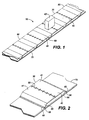
- Fig. 1 shows a material handling system or conveyor 10 that includes a substantially smooth surface conveyor comprised of a plurality of platforms or platforms 30 connected to an underlying conveyor base structure such as a conveyor belt 70 .
- the platforms 30 are connected to the underlying conveyor belt 70 by the insertion of the edges leading and trailing 60 of the platforms 30 beneath a pair of flexible platform edge retaining members 80 which form co-facing slots to accept the edges 60 of the platforms 30 .
- the conveyor 10 forms a closed loop and may be driven by a drive drum 120, to be described in detail below.
- each platform 30 may include a pair of ejection mechanisms 150 to eject items such as parcels 40 off conveyor to 10 a variety of output destinations such as a receiving chute, a parallel conveyor, or a non-parallel conveyor.
- the parcel 43 shown in Fig. 1, may be loaded onto conveyor 10 manually or by an induction conveyor (not shown).
- the ejection mechanisms 150 discharge the parcel 43 to a desired destination in a manner to be described in detail below.
- the conveyor 10 may be operated under the control of the digital controller, which may be a programmable logic controller (PLC) or a general purpose microprocessor which is found in a personal computer. Methods for programming such controllers to operate a material handling system of the type disclosed herein are conventional and known to those skilled in the art.
- Other sub-assemblies of the conveyor 10 include a hinged construction of the platform 30, as shown in Figs. 1-3, which allows the platform 30 to be quickly and easily attached and detached to and from the underlying conveyor belt 70 . The assemblies and sub-assemblies thus far noted and shown will now be described in detail.
- the conveyor 10 is comprised of a plurality of platforms 30 removably attached adjacent to the upper surface of a conveyor belt 70.
- the platforms 30 are formed from extruded aluminum. It is understood that platforms 30 may be formed primarily from other suitable materials such as plastic, steel or wood.
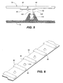
- the platform 30 is comprised of two panels 40 connected by an elongate hinge 50. As shown in Figs. 4 and 5, the elongate hinge 50 is mounted to the first and second panels 40 on the underside of the panels 40 .
- the hinge 50 may be a piano type hinge or other suitable hinge which allows the upper surface of the panels 40 to form the smooth surface of the platform 30 . As is well known to those skilled in the art, the hinge 50 may be mounted to the panels 40 by rivets or by countersunk screws to provide a smooth upper surface of platform 30 .
- the panels 40 terminate at edges 60 opposite the hinge 50 . Prior to the edge 60 of the panels 40 , the panels 40 form legs 55 terminating at bases 58 . Thus, as shown in Fig. 2, when a platform 30 is disposed onto the upper surface of a conveyor belt 70, the legs 55 and bases 58 of its panels 40 maintain the two upwardly-directed package supporting surfaces 41 of the platform 30 in a spaced apart relation with the underlying conveyor belt 70 .
- the conveyor 10 is formed by the insertion of the edges 60 of a plurality of platforms 30 into a plurality of co-facing slots formed by a plurality of flexible edge retainer members 80 .
- the flexible edge retainer members 80 are elongate members which run substantially the width of the conveyor belt 70 .
- the flexible edge retainer members 80 may be connected to the underlying conveyor belt by use of adhesives, cement, screws, or a variety of suitable attachment means.
- the platform 30 is attached to the conveyor belt 70 by flexing the panels 40 of the platform 30 about an axis formed by the hinge 50 .
- the length 90 between the leading and trailing edges 60 of the platform 30 is less than the distance between the co-facing slots formed by the edge retainer members 80 .
- the length of the platform 30 assumes a length approximate to the distance 100 between the flexible edge retainer members 80 .
- the top surface of the flexible edge retainer members 80 is substantially coplanar with the two upwardly-directed package supporting surfaces 41 of the platform 30 to provide a smooth transitional surface between adjacent platform 30.
- a center locking mechanism 103 is provided to secure each platform 30 into position with the edges 60 of the platform panels 40 engaging the co-facing slots formed by the flexible edge retainer members 80 .
- the center locking mechanisms 103 are preferably made from a suitable flexible material such as rubber or plastic to provide isolation of the platforms 30 from the underlying conveyor belt 70 . Such isolation serves to dampen vibration and noise and reduce wear.
- the center locking mechanism 103 is comprised of a center locking pin 105 connected to one of the mounting brackets 52 of the hinge 50 adjacent to the hinge 50 . As shown in Figs. 5 and 6, the center locking pin 105 is adapted for engagement with a center locking pin receptor 110 which is attached to the underlying conveyor belt 70.
- the individual platforms 30 flex about the hinge 50 .
- the closed loop conveyor system may be supported and driven by sprockets or other suitable drive mechanisms.
- the conveyor system 10 may be used to transport a variety of objects such as parcels or packages 43 shown in Fig. 1.
- the individual platforms 30 may be adapted to carry a variety of pieces of material handling equipment (not shown) such as baskets, bins, parts containers and material diverting systems. From the foregoing description, it should be readily understood that the modular construction of the conveyor 10 allows for the easy removal and replacement of individual platforms 30 for maintenance or to exchange a given platforms 30 with a platforms 30 containing one of a variety of material handling equipment as discussed above.
- a given platform 30 may be removed from the underlying conveyor belt 70 by lifting the platform 30 at or near the hinge 50 to disengage the center locking mechanism 103 and to disengage the edges 60 from the co-facing slots 85 formed by the flexible edge retaining members 80 .
- the conveyor system 10 can be operated quietly at relatively high rates of speed due to the isolation of adjacent platforms 30 from each other by the flexible edge retainer members 80 .
- one or each panel 40 of the platforms 30 may include a built-in mechanism for ejecting parcels from the surface of the platforms 30 .
- parcel ejection mechanisms 150 may be used to discharge items such as parcels 43 from the surface of the conveyor system 10 to a variety of output destinations.
- each panel 40 of the platforms 30 includes an elongate slot 160 for receiving a pusher number 170.
- the pusher member 170 is generally T-shaped and is disposed on the surface of the panels 40 of the platforms 30 so that the lower stem of the T-shaped pusher member 170 is inserted into the elongate slot 160 so that the pusher member 170 may slidably move across the width of the platforms 30 transverse to the direction of travel of the conveyor 10 .
- the lower stem 230 of the pusher member 170 extends down through the elongate slot 160 beneath the lower surface of the platforms panels 40 .
- a threaded opening (not shown) is provided in the lower stem 230 of each pusher member 170 for receiving a screw actuator 200 .
- the screw actuator 200 is driven by an electric motor 180 which drives screw actuator 200 via cog belt 220 and cog belt pulley 210 which is operatively attached to the screw actuator 200.
- one electric motor 180 may be utilized to power two pusher members 170, one attached to each of the panels 40 of the platforms 30 .
- each of the pusher members 170 may be powered by separate electric motors 180 if it is desired to operate the pusher members 170 separately. Such a configuration may be useful to rotate a larger package by actuating each pusher member 170 separately.
- a pair of electrical contacts 250 are attached relative to the platforms 30 and are electrically linked attached to the electric motor 180 via electric leads 240 .
- the electrical contacts 250 extend outwardly from and travel with the platforms.
- Fixed, stationary, power strips 260 are positioned off the conveyor system 10 and adjacent to desired discharge locations.
- the electrical contacts 250 can be spring loaded (not shown) to provide continuous and even contact between the electrical contacts 250 and the fixed power strips 260 .
- Energization of the electrical contacts 250 via the fixed power strips 260 energizes the electric motor 180 which in turn rotates the screw actuator 200 of the pusher members 170 to drive the pusher members 170 across the platform 30 at a high rate of speed and thereby discharge the parcel to the desired discharge location.
- the pusher members 170 of the panels 40 of the platforms 30 may be actuated simultaneously to eject a parcel from the surface of platform 30.
- a pusher member 170 may be powered by separate electric motors 180 in order to actuate the pusher members 170 at different times and at varying speeds to facilitate the rotation or positioning of a parcel along the surface of the platform 30 .
- the parcel ejection mechanism 150 is driven independently of the underlying conveying system by the energization of the electric motors 180 via electrical power contact 250 and fixed power bars 260 .
- a programmable logic controller at the parcel ejection mechanism 150 can be used to eject items at varying speeds as may be desired.
- the PLC may vary the speed of the electric motor 180 by positively or negatively ramping the electric current across the motor.
- the programmable logic controller may direct the pusher member 170 to return to the starting position or likewise to eject parcels to the opposite side of the platforms 30 by reversing the polarity of the current supplied to the electric motor 180 .
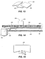
- a parcel ejection mechanism 270 shown in Fig. 12 may be mounted on the upper surface of the panels 40 of the platform 30 . This configuration provides for the ejection mechanism actuation equipment, to be described below, to be maintained above the surface of the platform 30 .
- the ejection mechanism 270 includes a generally T-shaped pusher member 275 , also shown in Fig. 15, and an ejection mechanism housing 290, shown in Fig. 13, an electric drive motor 310 and a cog belt 300 .
- the pusher member 275 slidably moves across the ejector mechanism housing 290 to eject an object positioned on the surface of the conveyor system 10 and adjacent to the pusher member 275.
- the lower stem of the pusher member 275 includes a toothed cut-out 280 for engagement with a cog belt 300 driven by the motor 310 shown at Figs. 12 and 14.
- the ejection mechanism housing 290 includes cover plates 295 and a sub-housing 297.
- Sub-housing 297 provides a protective enclosure for the cog belt 300 and the lower stem of the pusher member 275 as shown in Fig. 12.
- the cover plates 295 protect the ejection mechanism 270 and provide a smooth transitional surface between the surface of the platform 30 and the pusher member 275.
- the lower surface of the sub-housing 297 is attached to the upper surface of platform 30 .
- the parcel ejection mechanism housing 290 may be attached to the platform 30 using a variety of attachment means such as bolts, cement or adhesives.
- the alternate ejection mechanism 270 is powered by energization of electrical contacts operatively connected to electric motor 310 (not shown) in a manner as described for the preferred embodiment described above.
- a variety of alternate forms of parcel ejection mechanisms may be utilized with the conveyor system 10 involving the present invention.
- a lead screw driving a push plate or an air bellows member driving a push plate may be used atop the removable platforms.
- the present invention may be utilized to transfer objects such as parcels 43 to a variety of desired output locations.
- the platform 30 is lifted at or near the hinge 50 of the platform 30 . As shown in Fig. 3, lifting the platform as described, disengages the center locking mechanism 130 and allows for the edges 60 of the panels 40 of the platforms 30 to be disengaged from the co-facing slots 85 formed by the flexible edge retainer members 80 .
- the number and location of ejection mechanism 150 or 270 and the identification codes for each ejection mechanism may be input into the controller memory when movement of the conveyor systems 10 begins.
- Parcels 43 are induced sequentially onto the upstream end of the conveyor system 10 manually or automatically by an induction conveying system (not shown).
- a destination code for each parcel may be entered into the controller memory using a key pad (not shown), a voice recognition device (not shown), or an optical code reader (not shown), before the parcel is placed onto the conveyor system 10 as described above.
- the PLC will cause a pusher members 170 or 275 of the parcel ejection mechanisms 150 or 270 of the platforms 30 onto which the parcel 43 will be loaded to move to the left or right position by actuating the pusher members 170 or 275 via the electric motors 180 or 310 and the screw actuator 200 or cog belt 300, depending on which form of the ejection mechanism described above is utilized.
- the spring loaded electrical contacts 250 engage the fixed power bars 260 as shown in Fig. 11.
- the electric motor 180 or 310 will be energized via the power bars 260 and electrical contacts 250 to actuate the screw actuator 200 or cog belt 300 , as described above.
- the pusher members 170 or 275 are slidably actuated across the upper surface of the platforms 30 to discharge the parcel 43 off the upper surface of the platforms 30 and to the desired output destination.
- the PLC will reverse the polarity of the current to the electric motor, as described above, to return the pusher members 170 or 275 to the starting position.
- the PLC may leave the pusher members 170 or 275 in its current position to discharge a parcel subsequently loaded and directed to the opposite side.
Abstract
Description
said platforms each include a pivotable connection allowing respective leading and trailing edges to be moved closer together to allow disengagement of one platform from the associated platform retaining members without requiring the disengagement of any other platform. Other features of the invention will be apparent from the sub-claims.
Claims (11)
- A package conveyor (10) comprising a conveyor base structure (70); a plurality of platforms (30) thereon and each defining an upwardly directed package support surface (40), and leading and trailing edges (60); and a plurality of platform retaining members (80), one each between adjacent platforms (30) and attached to said base structure (70) for movement therewith, each retaining member (80) being configured to detachably accept and retain the adjacent leading and trailing edges of the platforms on either side thereof, characterised in that
said platforms (30) each include a pivotable connection (50) allowing respective leading and trailing edges to be moved closer together to allow disengagement of one platform (30) from the associated platform retaining members (80) without requiring the disengagement of any other platform (30). - The conveyor (10) of Claim 1, wherein said platforms (30) further comprise first and second panels (41), and wherein said pivotable connection (50) is provided by a hinge (50) intermediate and connecting said first and second panels (41).
- The conveyor (10) of claim 1 or claim 2 wherein
said platform retaining members (80) define at least two co-facing slots (85),
said platforms (30) having opposing edges (60) fitting into said slots (85) such that the conveyor base structure (70) carries said platform member (30). - The conveyor (10) of any preceding Claim, wherein said platform retaining members (80) are platform edge retaining members (80) and extend substantially the width of the conveyor base structure (70).
- The conveyor (10) of any preceding Claim, wherein said platform retaining members (80) each have an upper surface substantially continuous with the upper surfaces (40) of the adjacent platforms (30).
- The conveyor (10) of any preceding Claim, wherein said conveyor base structure (70) is an endless flexible belt and said platform retaining members (80) are attached to the outer surface of said conveyor base structure (70).
- The conveyor (10) of any preceding Claim, wherein said platforms (30) further comprise an ejection mechanism (150) for discharging objections (43) from atop said upwardly-directed package support surface (40).
- The conveyor (10) of any preceding claim wherein said conveyor base structure is a flexible conveyor belt (70); and said conveyor further includes conveyor belt drive means (120) configured to drive said conveyor belt (70), platform retaining members (80), and platforms (30) such that said platforms (30) can flex along respective pivotable connections (50).
- The conveyor (10) of claim 8, further comprising a flexible platform locking means (103) for securing said platforms (30) to said conveyor base structure (70) separate from one of said platform edges (60).
- The conveyor (10) of Claim 9, wherein said platform locking means (103) comprises:a platform locking pin (105) attached to a lower surface of a platform (30) medially of said platform (30); anda platform locking pin receptor (110) attached to said conveyor base structure (70) for receiving said platform locking pin (105).
- The conveyor (10) of claim 10 wherein said locking pin (105) is in the centre.
Priority Applications (1)
| Application Number | Priority Date | Filing Date | Title |
|---|---|---|---|
| DK98902820T DK1009690T3 (en) | 1997-01-22 | 1998-01-20 | Conveyor with removable material handling tray |
Applications Claiming Priority (3)
| Application Number | Priority Date | Filing Date | Title |
|---|---|---|---|
| US786246 | 1997-01-22 | ||
| US08/786,246 US5890584A (en) | 1997-01-22 | 1997-01-22 | Detachable material handling tray with automatic parcel ejection mechanism |
| PCT/US1998/001031 WO1998031615A1 (en) | 1997-01-22 | 1998-01-20 | Detachable material handling tray with automatic parcel ejection mechanism |
Publications (2)
| Publication Number | Publication Date |
|---|---|
| EP1009690A1 EP1009690A1 (en) | 2000-06-21 |
| EP1009690B1 true EP1009690B1 (en) | 2004-09-29 |
Family
ID=25138046
Family Applications (1)
| Application Number | Title | Priority Date | Filing Date |
|---|---|---|---|
| EP98902820A Expired - Lifetime EP1009690B1 (en) | 1997-01-22 | 1998-01-20 | Conveyor with detachable material handling tray |
Country Status (9)
| Country | Link |
|---|---|
| US (1) | US5890584A (en) |
| EP (1) | EP1009690B1 (en) |
| JP (1) | JP3349709B2 (en) |
| AT (1) | ATE277845T1 (en) |
| CA (1) | CA2278283C (en) |
| DE (1) | DE69826689T2 (en) |
| DK (1) | DK1009690T3 (en) |
| ES (1) | ES2229471T3 (en) |
| WO (1) | WO1998031615A1 (en) |
Families Citing this family (22)
| Publication number | Priority date | Publication date | Assignee | Title |
|---|---|---|---|---|
| US5868239A (en) | 1997-01-27 | 1999-02-09 | United Parcel Service Of America, Inc. | Conveyor including controlled package ejection capabilities |
| US5950798A (en) * | 1997-02-26 | 1999-09-14 | United Parcel Services Of America | Air distribution systems for shoe sorter |
| NL1007820C2 (en) * | 1997-12-17 | 1999-06-21 | Vanderlande Ind Nederland | Transport device. |
| JP3637263B2 (en) | 1999-06-07 | 2005-04-13 | アイテック株式会社 | Driving device for conveying device |
| US6323452B1 (en) | 1999-08-05 | 2001-11-27 | United Parcel Service Of America, Inc. | Feeding system and method for placing a plurality of objects on a tray of an automated sorting system |
| US6705452B2 (en) | 2002-05-13 | 2004-03-16 | Laitram, L.L.C. | Article-diverting conveyor belt and modules |
| US6802412B2 (en) * | 2002-11-19 | 2004-10-12 | The Laitram Corporation | Conveyor with a motorized transport element |
| US7261199B2 (en) * | 2004-06-29 | 2007-08-28 | Hartness International, Inc. | Neck gripping conveyor and link, and related rotary filler and system |
| US7278531B2 (en) * | 2004-06-29 | 2007-10-09 | Hartness International, Inc. | Flexible conveyor and connection elements |
| US7055677B2 (en) * | 2003-11-13 | 2006-06-06 | Hartness International, Inc. | Conveyor with movable grippers, and related conveyor link |
| US7036658B2 (en) | 2003-11-13 | 2006-05-02 | Hartness International, Inc. | Gripper conveyor with clear conveying path and related conveyor link |
| US7055676B2 (en) * | 2003-11-13 | 2006-06-06 | Hartness International, Inc. | Conveyor with movable gripper and related conveyor link |
| US7021453B2 (en) * | 2003-11-13 | 2006-04-04 | Hartness International, Inc. | Conveyor with gear mechanism gripper and related conveyor link |
| US7299832B2 (en) * | 2004-06-29 | 2007-11-27 | Hartness International, Inc. | Rotary filling machine and related components, and related method |
| US7331156B2 (en) * | 2004-06-29 | 2008-02-19 | Hartness International, Inc. | System for securely conveying articles and related components |
| US7185753B2 (en) * | 2004-09-28 | 2007-03-06 | Hartness International, Inc. | Shuttle conveyor |
| BRPI0814922A2 (en) * | 2007-08-22 | 2015-08-18 | Laitram Llc | "Conveyor Belt, Modular Conveyor Belt and Method of Operating a Conveyor Belt" |
| JP4536107B2 (en) | 2007-11-28 | 2010-09-01 | 株式会社椿本チエイン | Accumulated top plate conveyor |
| EP2903920B1 (en) * | 2012-10-03 | 2017-12-06 | Amazon Technologies, Inc. | Functional trays for handling products in a materials handling facility |
| US10934096B1 (en) * | 2019-06-21 | 2021-03-02 | Amazon Technologies, Inc. | Carrier bellows guards |
| EP3786089A1 (en) * | 2019-08-26 | 2021-03-03 | Siemens Aktiengesellschaft | Device and method for conveying and sorting piece goods |
| CN113479594B (en) * | 2021-06-01 | 2023-01-17 | 东阿阿胶股份有限公司 | Rubber block conveying and spacing system and method |
Family Cites Families (52)
| Publication number | Priority date | Publication date | Assignee | Title |
|---|---|---|---|---|
| DE352226C (en) * | 1922-04-24 | Julius Frisch | Link conveyor belt with metal plates arranged on a belt | |
| US2286332A (en) * | 1940-02-01 | 1942-06-16 | Chain Belt Co | Chain link attachment for traveling water screens |
| US2293121A (en) * | 1940-03-06 | 1942-08-18 | Le Roy Hanscom | Fruit turning and centering device |
| US2884118A (en) * | 1957-04-22 | 1959-04-28 | James R Williams | Articular conveyor chain |
| US2938621A (en) * | 1958-07-29 | 1960-05-31 | Aasted Kai Christian Sophus | Mould holder for chocolate moulding plants |
| US3026988A (en) * | 1959-04-06 | 1962-03-27 | Mathews Conveyer Co | Article transfer device |
| DE1183014B (en) * | 1961-04-20 | 1964-12-03 | Alfred Schmermund | Press chain for feeding tobacco, e.g. B. to tobacco cutters |
| GB1049372A (en) * | 1961-08-29 | 1966-11-23 | Auto Klean Strainers Ltd | Improvements relating to magnetic filters |
| FR1316628A (en) * | 1961-12-20 | 1963-02-01 | Aciers Sandvik | Metal belt conveyor |
| BE652454A (en) * | 1963-08-30 | |||
| DE1199183B (en) * | 1964-02-20 | 1965-08-19 | Gewerk Eisenhuette Westfalia | Apron conveyor |
| GB1046164A (en) * | 1964-03-23 | 1966-10-19 | Coalite Chem Prod Ltd | Bactericidal composition |
| US3262550A (en) * | 1964-05-11 | 1966-07-26 | Conveyor Specialties Company | Conveyor chain |
| US3481807A (en) * | 1965-08-11 | 1969-12-02 | Mitsubishi Belt Kk | Method of joining the ends of a conveyor belt reinforced with steel strands |
| US3348678A (en) * | 1966-01-10 | 1967-10-24 | Stanley L Flowers | Automatic weight grading apparatus |
| US3511357A (en) * | 1968-04-08 | 1970-05-12 | Scale Specialties Co | Conveyor switching device |
| GB1291115A (en) * | 1969-05-08 | 1972-09-27 | Atomic Energy Authority Uk | Improvements in or relating to conveyors |
| US3776349A (en) * | 1969-06-25 | 1973-12-04 | Conveyor Specialties Co | Fabricated flexible conveyor chain |
| US3788447A (en) * | 1972-07-03 | 1974-01-29 | Fmc Corp | Linear motor conveyor |
| DE2233063C2 (en) * | 1972-07-06 | 1984-05-24 | Hugo Stefan 8860 Nördlingen Müller | Slat conveyor |
| US3777877A (en) * | 1972-10-12 | 1973-12-11 | Stearns Manuf Co Inc | Conveyor assembly |
| DE2323601C2 (en) * | 1973-05-08 | 1984-11-29 | Hugo Stefan 8860 Nördlingen Müller | Slat conveyor |
| US4185737A (en) * | 1975-03-20 | 1980-01-29 | Blattermann Karl Gunther | Curve conveyor belt and method and apparatus for producing the same |
| GB1514708A (en) * | 1975-08-15 | 1978-06-21 | Gibbons Ltd J | Catch for windows and fanlights |
| US4078654A (en) * | 1976-05-10 | 1978-03-14 | The Sardee Corporation | Flexible coated wire cable conveyor structure |
| US4084687A (en) * | 1976-07-02 | 1978-04-18 | The Laitram Corporation | Conveyor having resilient conveying surface |
| US4128163A (en) * | 1977-04-11 | 1978-12-05 | Rockwell International Corporation | Cart conveyor system |
| US4170281A (en) * | 1977-06-30 | 1979-10-09 | The Laitram Corporation | Extrudable flexible modular tooth driven conveyor belt |
| US4227610A (en) * | 1978-05-22 | 1980-10-14 | Conrad Scholtz Ag | Curved belt conveyor |
| FR2462367A1 (en) * | 1979-07-25 | 1981-02-13 | Kleber Colombes | Bucket elevator with continuous belt conveyor - has brackets to support buckets, to give elevator transverse strength |
| IT1122898B (en) * | 1979-08-30 | 1986-04-30 | Francesco Canziani | SELECTION AND SORTING EQUIPMENT FOR OBJECTS |
| US4295559A (en) * | 1980-01-31 | 1981-10-20 | Acco Industries Inc. | Conveyor system with diverter |
| US4402393A (en) * | 1981-09-25 | 1983-09-06 | Western Electric Company, Incorporated | Conveyor driven fixtures which are precisely positionable at work stations |
| US4582193A (en) * | 1982-06-23 | 1986-04-15 | Bivans Corporation | Flight attached to a drive mechanism |
| US4537658A (en) * | 1982-09-30 | 1985-08-27 | Scapa Inc. | Papermakers fabric constructed of extruded slotted elements |
| IT1209579B (en) * | 1984-08-08 | 1989-08-30 | Macario Varese As | SYSTEM FOR THE SORTING OF PACKAGES, WITH AUTONOMOUS HANDLING TROLLEYS. |
| DE3571020D1 (en) * | 1984-08-20 | 1989-07-20 | Laitram Corp | Conveyor belt having insertable & selectable conveying members |
| US4682686A (en) * | 1985-01-16 | 1987-07-28 | Kyokuto Kaihatsu Kogyo Co., Ltd. | Articulated belt conveyor |
| GB2175560A (en) * | 1985-02-20 | 1986-12-03 | Baker Perkins Plc | Improvements in or relating to conveyors |
| KR870000221A (en) * | 1985-06-29 | 1987-02-17 | 데루노부 모모세 | Conveyor Link Belt |
| SU1316954A1 (en) * | 1985-12-29 | 1987-06-15 | Хабаровский политехнический институт | Longitudinal conveyer |
| SU1514708A1 (en) * | 1987-12-08 | 1989-10-15 | Khabarovsk Polt Inst | Longitudinal conveyer |
| US4875573A (en) * | 1988-07-11 | 1989-10-24 | Simplimatic Engineering Company | Wheel turn and hanger bracket assembly therefor |
| US4896760A (en) * | 1989-01-18 | 1990-01-30 | The Buschman Company | Pusher elements and cross tubes for a sortation conveyor for products with high-friction surfaces |
| JPH02221007A (en) * | 1989-02-21 | 1990-09-04 | Uingu Haisera:Kk | Conveyer belt |
| JP3018005B2 (en) * | 1989-09-05 | 2000-03-13 | 株式会社エレッツ | Conveyor equipment |
| US5127510A (en) * | 1990-10-31 | 1992-07-07 | Rapistan Demag Corporation | Modular diverter shoe and slat construction |
| US5176247A (en) * | 1991-08-12 | 1993-01-05 | Rexnord Corporation | Sideflexing conveyor chain including low centerline hinge pin |
| US5388681A (en) * | 1992-10-19 | 1995-02-14 | United Parcel Service Of America, Inc. | Inflatable conveyor belt |
| DE4244170C2 (en) * | 1992-12-24 | 1995-10-05 | Axmann Foerdertechnik | Belt conveyor |
| US5421446A (en) * | 1993-03-12 | 1995-06-06 | United Parcel Service Of America, Inc. | Article diverter apparatus for use in conveyor systems |
| US5433311A (en) * | 1993-11-17 | 1995-07-18 | United Parcel Service Of America, Inc. | Dual level tilting tray package sorting apparatus |
-
1997
- 1997-01-22 US US08/786,246 patent/US5890584A/en not_active Expired - Lifetime
-
1998
- 1998-01-20 AT AT98902820T patent/ATE277845T1/en not_active IP Right Cessation
- 1998-01-20 EP EP98902820A patent/EP1009690B1/en not_active Expired - Lifetime
- 1998-01-20 ES ES98902820T patent/ES2229471T3/en not_active Expired - Lifetime
- 1998-01-20 JP JP53463998A patent/JP3349709B2/en not_active Expired - Fee Related
- 1998-01-20 WO PCT/US1998/001031 patent/WO1998031615A1/en active IP Right Grant
- 1998-01-20 DE DE69826689T patent/DE69826689T2/en not_active Expired - Lifetime
- 1998-01-20 CA CA002278283A patent/CA2278283C/en not_active Expired - Fee Related
- 1998-01-20 DK DK98902820T patent/DK1009690T3/en active
Also Published As
| Publication number | Publication date |
|---|---|
| JP2002503193A (en) | 2002-01-29 |
| JP3349709B2 (en) | 2002-11-25 |
| CA2278283A1 (en) | 1998-07-23 |
| CA2278283C (en) | 2004-10-19 |
| DE69826689T2 (en) | 2005-10-06 |
| WO1998031615A1 (en) | 1998-07-23 |
| EP1009690A1 (en) | 2000-06-21 |
| ES2229471T3 (en) | 2005-04-16 |
| DK1009690T3 (en) | 2005-01-17 |
| US5890584A (en) | 1999-04-06 |
| DE69826689D1 (en) | 2004-11-04 |
| ATE277845T1 (en) | 2004-10-15 |
Similar Documents
| Publication | Publication Date | Title |
|---|---|---|
| EP1009690B1 (en) | Conveyor with detachable material handling tray | |
| EP0864513B1 (en) | Tray package sorting apparatus | |
| US6561339B1 (en) | Automatic tray handling system for sorter | |
| US5385243A (en) | Modular system for automatically staging letters in connection with a letter sorting machine | |
| EP0954497A1 (en) | Automated lateral translation conveyor | |
| EP0806384A2 (en) | A conveying system | |
| CA2190271C (en) | Tilting tray package sorting apparatus | |
| US5435429A (en) | Conveyor | |
| CA2283844C (en) | Side conveyor disc including quick-change features | |
| CN110395545A (en) | The Sorting & Picking System of device is removed with article | |
| US5967290A (en) | High speed bobbin-type sorter for parcels | |
| US3371769A (en) | Elevator conveyor | |
| CN213855749U (en) | Letter sorting system with canceling release mechanical system | |
| US4770286A (en) | Workpiece elevator | |
| CN115415178A (en) | Small-size arm is used in commodity circulation letter sorting | |
| CA2096701C (en) | System for automatically staging letters used in connection with a letter sorting machine | |
| SU1299772A1 (en) | Automatic assembly line | |
| JPH0117896B2 (en) |
Legal Events
| Date | Code | Title | Description |
|---|---|---|---|
| PUAI | Public reference made under article 153(3) epc to a published international application that has entered the european phase |
Free format text: ORIGINAL CODE: 0009012 |
|
| 17P | Request for examination filed |
Effective date: 19990730 |
|
| AK | Designated contracting states |
Kind code of ref document: A1 Designated state(s): AT BE CH DE DK ES FI FR GB GR IE IT LI LU MC NL PT SE |
|
| 17Q | First examination report despatched |
Effective date: 20030904 |
|
| GRAP | Despatch of communication of intention to grant a patent |
Free format text: ORIGINAL CODE: EPIDOSNIGR1 |
|
| RTI1 | Title (correction) |
Free format text: CONVEYOR WITH DETACHABLE MATERIAL HANDLING TRAY |
|
| GRAS | Grant fee paid |
Free format text: ORIGINAL CODE: EPIDOSNIGR3 |
|
| GRAA | (expected) grant |
Free format text: ORIGINAL CODE: 0009210 |
|
| AK | Designated contracting states |
Kind code of ref document: B1 Designated state(s): AT BE CH DE DK ES FI FR GB GR IE IT LI LU MC NL PT SE |
|
| PG25 | Lapsed in a contracting state [announced via postgrant information from national office to epo] |
Ref country code: FI Free format text: LAPSE BECAUSE OF FAILURE TO SUBMIT A TRANSLATION OF THE DESCRIPTION OR TO PAY THE FEE WITHIN THE PRESCRIBED TIME-LIMIT Effective date: 20040929 Ref country code: AT Free format text: LAPSE BECAUSE OF FAILURE TO SUBMIT A TRANSLATION OF THE DESCRIPTION OR TO PAY THE FEE WITHIN THE PRESCRIBED TIME-LIMIT Effective date: 20040929 |
|
| REG | Reference to a national code |
Ref country code: GB Ref legal event code: FG4D |
|
| REG | Reference to a national code |
Ref country code: CH Ref legal event code: EP |
|
| REG | Reference to a national code |
Ref country code: IE Ref legal event code: FG4D |
|
| REF | Corresponds to: |
Ref document number: 69826689 Country of ref document: DE Date of ref document: 20041104 Kind code of ref document: P |
|
| REG | Reference to a national code |
Ref country code: CH Ref legal event code: NV Representative=s name: KELLER & PARTNER PATENTANWAELTE AG |
|
| REG | Reference to a national code |
Ref country code: SE Ref legal event code: TRGR |
|
| PG25 | Lapsed in a contracting state [announced via postgrant information from national office to epo] |
Ref country code: GR Free format text: LAPSE BECAUSE OF FAILURE TO SUBMIT A TRANSLATION OF THE DESCRIPTION OR TO PAY THE FEE WITHIN THE PRESCRIBED TIME-LIMIT Effective date: 20041229 |
|
| REG | Reference to a national code |
Ref country code: DK Ref legal event code: T3 |
|
| PG25 | Lapsed in a contracting state [announced via postgrant information from national office to epo] |
Ref country code: LU Free format text: LAPSE BECAUSE OF NON-PAYMENT OF DUE FEES Effective date: 20050120 Ref country code: IE Free format text: LAPSE BECAUSE OF NON-PAYMENT OF DUE FEES Effective date: 20050120 |
|
| PG25 | Lapsed in a contracting state [announced via postgrant information from national office to epo] |
Ref country code: MC Free format text: LAPSE BECAUSE OF NON-PAYMENT OF DUE FEES Effective date: 20050131 |
|
| REG | Reference to a national code |
Ref country code: ES Ref legal event code: FG2A Ref document number: 2229471 Country of ref document: ES Kind code of ref document: T3 |
|
| ET | Fr: translation filed | ||
| PLBE | No opposition filed within time limit |
Free format text: ORIGINAL CODE: 0009261 |
|
| STAA | Information on the status of an ep patent application or granted ep patent |
Free format text: STATUS: NO OPPOSITION FILED WITHIN TIME LIMIT |
|
| 26N | No opposition filed |
Effective date: 20050630 |
|
| REG | Reference to a national code |
Ref country code: IE Ref legal event code: MM4A |
|
| PGFP | Annual fee paid to national office [announced via postgrant information from national office to epo] |
Ref country code: NL Payment date: 20070103 Year of fee payment: 10 |
|
| PGFP | Annual fee paid to national office [announced via postgrant information from national office to epo] |
Ref country code: SE Payment date: 20070104 Year of fee payment: 10 |
|
| PGFP | Annual fee paid to national office [announced via postgrant information from national office to epo] |
Ref country code: DK Payment date: 20070115 Year of fee payment: 10 Ref country code: CH Payment date: 20070115 Year of fee payment: 10 |
|
| PG25 | Lapsed in a contracting state [announced via postgrant information from national office to epo] |
Ref country code: PT Free format text: LAPSE BECAUSE OF NON-PAYMENT OF DUE FEES Effective date: 20050228 |
|
| REG | Reference to a national code |
Ref country code: CH Ref legal event code: PL |
|
| REG | Reference to a national code |
Ref country code: DK Ref legal event code: EBP |
|
| EUG | Se: european patent has lapsed | ||
| NLV4 | Nl: lapsed or anulled due to non-payment of the annual fee |
Effective date: 20080801 |
|
| PG25 | Lapsed in a contracting state [announced via postgrant information from national office to epo] |
Ref country code: NL Free format text: LAPSE BECAUSE OF NON-PAYMENT OF DUE FEES Effective date: 20080801 Ref country code: LI Free format text: LAPSE BECAUSE OF NON-PAYMENT OF DUE FEES Effective date: 20080131 Ref country code: CH Free format text: LAPSE BECAUSE OF NON-PAYMENT OF DUE FEES Effective date: 20080131 |
|
| PG25 | Lapsed in a contracting state [announced via postgrant information from national office to epo] |
Ref country code: SE Free format text: LAPSE BECAUSE OF NON-PAYMENT OF DUE FEES Effective date: 20080121 Ref country code: DK Free format text: LAPSE BECAUSE OF NON-PAYMENT OF DUE FEES Effective date: 20080131 |
|
| PGFP | Annual fee paid to national office [announced via postgrant information from national office to epo] |
Ref country code: IT Payment date: 20120113 Year of fee payment: 15 |
|
| PGFP | Annual fee paid to national office [announced via postgrant information from national office to epo] |
Ref country code: GB Payment date: 20130116 Year of fee payment: 16 Ref country code: DE Payment date: 20130116 Year of fee payment: 16 Ref country code: FR Payment date: 20130204 Year of fee payment: 16 Ref country code: ES Payment date: 20130207 Year of fee payment: 16 |
|
| PGFP | Annual fee paid to national office [announced via postgrant information from national office to epo] |
Ref country code: BE Payment date: 20130114 Year of fee payment: 16 |
|
| BERE | Be: lapsed |
Owner name: *UNITED PARCEL SERVICE OF AMERICA INC. Effective date: 20140131 |
|
| REG | Reference to a national code |
Ref country code: DE Ref legal event code: R119 Ref document number: 69826689 Country of ref document: DE |
|
| GBPC | Gb: european patent ceased through non-payment of renewal fee |
Effective date: 20140120 |
|
| REG | Reference to a national code |
Ref country code: DE Ref legal event code: R119 Ref document number: 69826689 Country of ref document: DE Effective date: 20140801 |
|
| PG25 | Lapsed in a contracting state [announced via postgrant information from national office to epo] |
Ref country code: DE Free format text: LAPSE BECAUSE OF NON-PAYMENT OF DUE FEES Effective date: 20140801 |
|
| REG | Reference to a national code |
Ref country code: FR Ref legal event code: ST Effective date: 20140930 |
|
| PG25 | Lapsed in a contracting state [announced via postgrant information from national office to epo] |
Ref country code: GB Free format text: LAPSE BECAUSE OF NON-PAYMENT OF DUE FEES Effective date: 20140120 Ref country code: FR Free format text: LAPSE BECAUSE OF NON-PAYMENT OF DUE FEES Effective date: 20140131 |
|
| PG25 | Lapsed in a contracting state [announced via postgrant information from national office to epo] |
Ref country code: BE Free format text: LAPSE BECAUSE OF NON-PAYMENT OF DUE FEES Effective date: 20140131 |
|
| REG | Reference to a national code |
Ref country code: ES Ref legal event code: FD2A Effective date: 20150330 |
|
| PG25 | Lapsed in a contracting state [announced via postgrant information from national office to epo] |
Ref country code: ES Free format text: LAPSE BECAUSE OF NON-PAYMENT OF DUE FEES Effective date: 20140121 |
|
| PG25 | Lapsed in a contracting state [announced via postgrant information from national office to epo] |
Ref country code: IT Free format text: LAPSE BECAUSE OF NON-PAYMENT OF DUE FEES Effective date: 20140120 |