EP1009210A2 - Ein Gehäuse for eine elektrische Schaltung - Google Patents
Ein Gehäuse for eine elektrische Schaltung Download PDFInfo
- Publication number
- EP1009210A2 EP1009210A2 EP99309844A EP99309844A EP1009210A2 EP 1009210 A2 EP1009210 A2 EP 1009210A2 EP 99309844 A EP99309844 A EP 99309844A EP 99309844 A EP99309844 A EP 99309844A EP 1009210 A2 EP1009210 A2 EP 1009210A2
- Authority
- EP
- European Patent Office
- Prior art keywords
- housing
- slit
- panel
- portions
- raised
- Prior art date
- Legal status (The legal status is an assumption and is not a legal conclusion. Google has not performed a legal analysis and makes no representation as to the accuracy of the status listed.)
- Withdrawn
Links
Images

Classifications
-
- H—ELECTRICITY
- H05—ELECTRIC TECHNIQUES NOT OTHERWISE PROVIDED FOR
- H05K—PRINTED CIRCUITS; CASINGS OR CONSTRUCTIONAL DETAILS OF ELECTRIC APPARATUS; MANUFACTURE OF ASSEMBLAGES OF ELECTRICAL COMPONENTS
- H05K7/00—Constructional details common to different types of electric apparatus
- H05K7/14—Mounting supporting structure in casing or on frame or rack
- H05K7/1417—Mounting supporting structure in casing or on frame or rack having securing means for mounting boards, plates or wiring boards
- H05K7/1418—Card guides, e.g. grooves
Definitions
- This invention relates to improvements in housings for an electrical circuit, and in particular but not exclusively to a housing comprising a frame member and at least one support member adapted to support a number of electrical components within the housing.
- a casing for the support assemblies may include an elongate guide rail which co-operates with one end of the printed circuit board to allow each support assembly to be slid into and out of the casing.
- the guide rail may also serve to lock the PCB in place and provide electrical connection to components on the PCB.
- the invention provides a housing for an electrical circuit comprising a frame member and at least one support member, the support member being adapted to support at least part of the electrical circuit within the frame, wherein one of the members includes a sheet metal panel including a number of raised portions having aligned elongate slits formed therein into which a guide rail defined by part of the other member is adapted to be slidably received.
- the support member comprises a guide rail and the raised portions having slits are formed on the frame member.
- the frame member comprises a box like structure formed at least partially from sheet metal/with the raised portions provided at the top and bottom.
- a guide rail provided at the top and bottom of the support member co-operates respectively with the raised portions on the top and bottom of the casing.
- the guide rail may be simply provided by an edge of a sheet metal panel forming part of the support member.
- the edge of the panel may first be folded back on itself to form a smooth edge to assist in sliding relative to the casing.
- two, three or four or more support members may be slidably received within the frame member.
- a number of groups of raised and slit portions may be provided, each group co-operating with a respective support member.
- depressed and slit portions may be provided which extend out of the plane of the sheet metal in the opposite direction to the raised and slit portions. They may be substantially identical in construction to the raised portions.
- the raised (or depressed) and slit portions may be easily produced in a flat metal sheet using any standard computer numerical control (CNC) process.
- CNC computer numerical control
- they are formed by first cutting or stamping an elongate slit into the sheet. An area of metal around the slit can then be punched or otherwise deformed to deform the edges of the slit and a portion of the surrounding metal out of the plane of the sheet.
- the slit may be formed after deforming the metal out of the plane of the sheet, or substantially simultaneously.
- a substantially circular area of metal having a diameter substantially equal to or less than the length of its respective slit is deformed to produce a truncated frusto-conical portion out of the plane of the sheet.
- Another preferred shape is that of a dome with a slit running across its diameter to split the dome into two halves.
- the frame member may include a dividing panel, for example dividing the casing into two halves horizontally with one above the other.
- raised and slit portions and depressed and slit portions may be provided on opposing sides of the dividing panel to guide support assemblies, located in each half of the casing, i.e. above and below the divider.
- the metal sheet panel may be steel or aluminium or any other metal which can be permanently deformed to produce the raised portions. It is also envisaged that other non-metal sheet material may be suitable.
- the frame member comprises a substantially box-like structure comprising sheet metal side panels, a sheet metal top panel, bottom panel and rear panel.
- the raised and slit portions may project into the casing from the top and bottom panels so the support assemblies can be slid into the casing alongside one another.
- the raised and slit portions may project into the frame member from the side panels to enable the support members to be slid into the frame member above one another.
- the invention provides a motor controller comprising a motor control circuit contained at least partially within a housing in accordance with the first aspect of the invention.
- the invention in another aspect, provides a system of slidably engaging a first assembly with a second assembly by co-operation between raised and slit portions of a sheet metal plate forming a part of the first assembly and an elongate rail forming a part of the second assembly, said rail being adapted to slide within said slits in said portions.
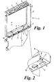
- a housing 1 comprising a top panel 2, a bottom panel 3 and a back panel 4 defines a frame member.
- a single side panel 5 is also visible in Figure 3, attached to the remaining panels by bolts (not shown) in holes 6.
- the top, back and bottom panel are fabricated by folding a single sheet of metal.
- a number of inwardly directed raised and slotted portions 7 are provided in the top panel 2.
- a number of identical inwardly directed raised and slotted portions 7 are also formed into the bottom panel 3. The portions 7 all project into the housing and act as a guide for a support member 10.
- FIG. 2 of the accompanying drawings An enlarged view of a portion of Figure 1 is shown in Figure 2 of the accompanying drawings showing the raised and slit portions 7 in more detail.
- Each one comprises a slot 8 formed into the panel, with a portion of metal 9 surrounding the slot 8 deformed out of the plane of the metal sheet to form a truncated frusto-cone bisected by the slot 8.
- the top panel 2 has four such portions arranged spaced apart in a row, each one having a slot aligned axially with the slot in the remaining portions.
- the bottom panel 3 also has four such portions, the slots of these also being aligned and the portions being spaced apart in a row.
- the support member 10 comprises a sheet metal pressing onto which a portion of an electrical circuit (not shown) can be mounted.
- a top edge and bottom edge of the sheet is adapted to co-operate with the portions 7 in the top and bottom panels 2,3 respectively to allow the support assembly 10 to be slid into and out of the housing 1 along the slots.
- a second set of portions are formed into the bottom panel. These depend downwards out of the housing and one adaptor to co-operate with a second support assembly on the outside of the bottom panel (i.e. other side to the first support assembly).
- the support assembly that is received within the housing is shown partially withdrawn from the housing.
- the housing does not need to completely encase the support assemblies. Indeed, as shown, in Figure 4 the housing may be adapted to form part of a larger housing assembly 100 with the bottom panel forming an intermediate divider as shown. Of course, the housing 1 could be modified to completely encase the support assemblies if required.
Landscapes
- Engineering & Computer Science (AREA)
- Microelectronics & Electronic Packaging (AREA)
- Casings For Electric Apparatus (AREA)
Applications Claiming Priority (2)
| Application Number | Priority Date | Filing Date | Title |
|---|---|---|---|
| GB9826834 | 1998-12-07 | ||
| GB9826834A GB2344695A (en) | 1998-12-07 | 1998-12-07 | A housing for an electrical circuit |
Publications (2)
| Publication Number | Publication Date |
|---|---|
| EP1009210A2 true EP1009210A2 (de) | 2000-06-14 |
| EP1009210A3 EP1009210A3 (de) | 2001-01-10 |
Family
ID=10843741
Family Applications (1)
| Application Number | Title | Priority Date | Filing Date |
|---|---|---|---|
| EP99309844A Withdrawn EP1009210A3 (de) | 1998-12-07 | 1999-12-07 | Ein Gehäuse for eine elektrische Schaltung |
Country Status (2)
| Country | Link |
|---|---|
| EP (1) | EP1009210A3 (de) |
| GB (1) | GB2344695A (de) |
Cited By (3)
| Publication number | Priority date | Publication date | Assignee | Title |
|---|---|---|---|---|
| WO2002096173A3 (en) * | 2001-05-18 | 2003-11-06 | Adc Telecommunications Inc | Telecommunications chassis and card |
| CN105834678A (zh) * | 2015-04-22 | 2016-08-10 | 维沃移动通信有限公司 | 一种结构件的制造方法 |
| CN105834677A (zh) * | 2015-04-22 | 2016-08-10 | 维沃移动通信有限公司 | 一种结构件的制造方法 |
Family Cites Families (6)
| Publication number | Priority date | Publication date | Assignee | Title |
|---|---|---|---|---|
| US3603845A (en) * | 1970-07-09 | 1971-09-07 | Wescom | Expandable enclosure for printed circuit cards and the like |
| FR2559335B1 (fr) * | 1984-02-08 | 1986-05-23 | Telemecanique Electrique | Cellule modulaire de support et de protection de cartes electroniques |
| EP0270065B1 (de) * | 1986-12-03 | 1992-02-19 | Siemens Aktiengesellschaft | Steckeinschub für elektrische Nachrichtentechnik |
| GB2219693B (en) * | 1988-06-10 | 1992-09-02 | Schlumberger Electronics | Case structure |
| US5036313A (en) * | 1989-08-25 | 1991-07-30 | Micronics Computers, Inc. | Portable computer with improved assembly design |
| DE9006503U1 (de) * | 1990-06-08 | 1991-10-10 | Siemens Nixdorf Informationssysteme AG, 4790 Paderborn | Gerätewand mit Führungsbahnen für Einschub-Baugruppenträger |
-
1998
- 1998-12-07 GB GB9826834A patent/GB2344695A/en not_active Withdrawn
-
1999
- 1999-12-07 EP EP99309844A patent/EP1009210A3/de not_active Withdrawn
Cited By (6)
| Publication number | Priority date | Publication date | Assignee | Title |
|---|---|---|---|---|
| WO2002096173A3 (en) * | 2001-05-18 | 2003-11-06 | Adc Telecommunications Inc | Telecommunications chassis and card |
| US7245717B2 (en) | 2001-05-18 | 2007-07-17 | Adc Telecommunications, Inc. | Telecommunications chassis and card |
| US7725142B2 (en) | 2001-05-18 | 2010-05-25 | Adc Telecommunications, Inc. | Telecommunications chassis and card |
| US8014837B2 (en) | 2001-05-18 | 2011-09-06 | Adc Telecommunications, Inc. | Telecommunications chassis and card |
| CN105834678A (zh) * | 2015-04-22 | 2016-08-10 | 维沃移动通信有限公司 | 一种结构件的制造方法 |
| CN105834677A (zh) * | 2015-04-22 | 2016-08-10 | 维沃移动通信有限公司 | 一种结构件的制造方法 |
Also Published As
| Publication number | Publication date |
|---|---|
| GB9826834D0 (en) | 1999-01-27 |
| GB2344695A (en) | 2000-06-14 |
| EP1009210A3 (de) | 2001-01-10 |
Similar Documents
| Publication | Publication Date | Title |
|---|---|---|
| EP2683230B1 (de) | Kastengehäuse | |
| US5392629A (en) | Method and apparatus for forming multi-level features in an object | |
| EP0898444B1 (de) | Gehäuse zur Aufnahme von elektrischen Baugruppen | |
| US5016142A (en) | Printed circuit board guide apparatus for a limited access area | |
| DE10304278A1 (de) | Struktur zur Befestigung einer zentralen Anzeigeeinheit | |
| WO1997034453A1 (de) | Baugruppe eines elektrischen gerätes | |
| EP1356556B1 (de) | Verteilungssystem der energietechnik zur versorgung elektrischer verbraucher | |
| DE3837029C2 (de) | ||
| EP1009210A2 (de) | Ein Gehäuse for eine elektrische Schaltung | |
| EP1426248B1 (de) | Gassackmodul | |
| EP1237395B1 (de) | Leiterplattenanordnung | |
| US6313997B1 (en) | Bump-configured, perforated-plate architecture for housing printed circuit boards without EMI leaks | |
| DE19817089C1 (de) | Baugruppenträger | |
| DE19609887C1 (de) | Gerätechassis für elektronische Geräte | |
| DE19644418C1 (de) | Baugruppenträger | |
| DE69206330T2 (de) | Steuergerät mit Klemmeinrichtung. | |
| EP0553399B1 (de) | Aufbausystem für Gehäuse der elektrischen Nachrichtentechnik | |
| EP0934591B1 (de) | Baugruppe für ein aufbausystem | |
| DE69505222T2 (de) | Einschub für elektronische Karten | |
| EP1102527B1 (de) | Abschirmgehäuse mit ESD-Schutz | |
| EP0886992A1 (de) | Gerätechassis für elektronische geräte | |
| US5641301A (en) | Lead-in guide for printed circuit boards | |
| DE3409021A1 (de) | Vorrichtung zur befestigung und zum auswerfen von elektronischen baugruppen | |
| EP0508002B1 (de) | Kassette zum Einbau in einen Baugruppenträger | |
| EP1845763A2 (de) | Gehäuse für die Aufnahme von Leiterkarten und/oder weiteren elektronischen und/oder elektrischen Komponenten |
Legal Events
| Date | Code | Title | Description |
|---|---|---|---|
| PUAI | Public reference made under article 153(3) epc to a published international application that has entered the european phase |
Free format text: ORIGINAL CODE: 0009012 |
|
| AK | Designated contracting states |
Kind code of ref document: A2 Designated state(s): AT BE CH CY DE DK ES FI FR GB GR IE IT LI LU MC NL PT SE |
|
| AX | Request for extension of the european patent |
Free format text: AL;LT;LV;MK;RO;SI |
|
| PUAL | Search report despatched |
Free format text: ORIGINAL CODE: 0009013 |
|
| AK | Designated contracting states |
Kind code of ref document: A3 Designated state(s): AT BE CH CY DE DK ES FI FR GB GR IE IT LI LU MC NL PT SE |
|
| AX | Request for extension of the european patent |
Free format text: AL;LT;LV;MK;RO;SI |
|
| STAA | Information on the status of an ep patent application or granted ep patent |
Free format text: STATUS: THE APPLICATION HAS BEEN WITHDRAWN |
|
| 18W | Application withdrawn |
Withdrawal date: 20010725 |