EP1008527A1 - Injection moulded plastic crate - Google Patents
Injection moulded plastic crate Download PDFInfo
- Publication number
- EP1008527A1 EP1008527A1 EP99203748A EP99203748A EP1008527A1 EP 1008527 A1 EP1008527 A1 EP 1008527A1 EP 99203748 A EP99203748 A EP 99203748A EP 99203748 A EP99203748 A EP 99203748A EP 1008527 A1 EP1008527 A1 EP 1008527A1
- Authority
- EP
- European Patent Office
- Prior art keywords
- crate
- mould
- label
- plate
- relief
- Prior art date
- Legal status (The legal status is an assumption and is not a legal conclusion. Google has not performed a legal analysis and makes no representation as to the accuracy of the status listed.)
- Granted
Links
Images

Classifications
-
- B—PERFORMING OPERATIONS; TRANSPORTING
- B29—WORKING OF PLASTICS; WORKING OF SUBSTANCES IN A PLASTIC STATE IN GENERAL
- B29C—SHAPING OR JOINING OF PLASTICS; SHAPING OF MATERIAL IN A PLASTIC STATE, NOT OTHERWISE PROVIDED FOR; AFTER-TREATMENT OF THE SHAPED PRODUCTS, e.g. REPAIRING
- B29C45/00—Injection moulding, i.e. forcing the required volume of moulding material through a nozzle into a closed mould; Apparatus therefor
- B29C45/14—Injection moulding, i.e. forcing the required volume of moulding material through a nozzle into a closed mould; Apparatus therefor incorporating preformed parts or layers, e.g. injection moulding around inserts or for coating articles
- B29C45/1418—Injection moulding, i.e. forcing the required volume of moulding material through a nozzle into a closed mould; Apparatus therefor incorporating preformed parts or layers, e.g. injection moulding around inserts or for coating articles the inserts being deformed or preformed, e.g. by the injection pressure
-
- B—PERFORMING OPERATIONS; TRANSPORTING
- B29—WORKING OF PLASTICS; WORKING OF SUBSTANCES IN A PLASTIC STATE IN GENERAL
- B29C—SHAPING OR JOINING OF PLASTICS; SHAPING OF MATERIAL IN A PLASTIC STATE, NOT OTHERWISE PROVIDED FOR; AFTER-TREATMENT OF THE SHAPED PRODUCTS, e.g. REPAIRING
- B29C45/00—Injection moulding, i.e. forcing the required volume of moulding material through a nozzle into a closed mould; Apparatus therefor
- B29C45/14—Injection moulding, i.e. forcing the required volume of moulding material through a nozzle into a closed mould; Apparatus therefor incorporating preformed parts or layers, e.g. injection moulding around inserts or for coating articles
- B29C45/14065—Positioning or centering articles in the mould
-
- B—PERFORMING OPERATIONS; TRANSPORTING
- B65—CONVEYING; PACKING; STORING; HANDLING THIN OR FILAMENTARY MATERIAL
- B65D—CONTAINERS FOR STORAGE OR TRANSPORT OF ARTICLES OR MATERIALS, e.g. BAGS, BARRELS, BOTTLES, BOXES, CANS, CARTONS, CRATES, DRUMS, JARS, TANKS, HOPPERS, FORWARDING CONTAINERS; ACCESSORIES, CLOSURES, OR FITTINGS THEREFOR; PACKAGING ELEMENTS; PACKAGES
- B65D1/00—Containers having bodies formed in one piece, e.g. by casting metallic material, by moulding plastics, by blowing vitreous material, by throwing ceramic material, by moulding pulped fibrous material, by deep-drawing operations performed on sheet material
- B65D1/22—Boxes or like containers with side walls of substantial depth for enclosing contents
- B65D1/24—Boxes or like containers with side walls of substantial depth for enclosing contents with moulded compartments or partitions
- B65D1/243—Crates for bottles or like containers
-
- B—PERFORMING OPERATIONS; TRANSPORTING
- B65—CONVEYING; PACKING; STORING; HANDLING THIN OR FILAMENTARY MATERIAL
- B65D—CONTAINERS FOR STORAGE OR TRANSPORT OF ARTICLES OR MATERIALS, e.g. BAGS, BARRELS, BOTTLES, BOXES, CANS, CARTONS, CRATES, DRUMS, JARS, TANKS, HOPPERS, FORWARDING CONTAINERS; ACCESSORIES, CLOSURES, OR FITTINGS THEREFOR; PACKAGING ELEMENTS; PACKAGES
- B65D25/00—Details of other kinds or types of rigid or semi-rigid containers
- B65D25/34—Coverings or external coatings
- B65D25/36—Coverings or external coatings formed by applying sheet material
-
- B—PERFORMING OPERATIONS; TRANSPORTING
- B29—WORKING OF PLASTICS; WORKING OF SUBSTANCES IN A PLASTIC STATE IN GENERAL
- B29C—SHAPING OR JOINING OF PLASTICS; SHAPING OF MATERIAL IN A PLASTIC STATE, NOT OTHERWISE PROVIDED FOR; AFTER-TREATMENT OF THE SHAPED PRODUCTS, e.g. REPAIRING
- B29C45/00—Injection moulding, i.e. forcing the required volume of moulding material through a nozzle into a closed mould; Apparatus therefor
- B29C45/14—Injection moulding, i.e. forcing the required volume of moulding material through a nozzle into a closed mould; Apparatus therefor incorporating preformed parts or layers, e.g. injection moulding around inserts or for coating articles
- B29C45/14065—Positioning or centering articles in the mould
- B29C2045/14155—Positioning or centering articles in the mould using vacuum or suction
-
- B—PERFORMING OPERATIONS; TRANSPORTING
- B29—WORKING OF PLASTICS; WORKING OF SUBSTANCES IN A PLASTIC STATE IN GENERAL
- B29C—SHAPING OR JOINING OF PLASTICS; SHAPING OF MATERIAL IN A PLASTIC STATE, NOT OTHERWISE PROVIDED FOR; AFTER-TREATMENT OF THE SHAPED PRODUCTS, e.g. REPAIRING
- B29C45/00—Injection moulding, i.e. forcing the required volume of moulding material through a nozzle into a closed mould; Apparatus therefor
- B29C45/14—Injection moulding, i.e. forcing the required volume of moulding material through a nozzle into a closed mould; Apparatus therefor incorporating preformed parts or layers, e.g. injection moulding around inserts or for coating articles
- B29C45/1418—Injection moulding, i.e. forcing the required volume of moulding material through a nozzle into a closed mould; Apparatus therefor incorporating preformed parts or layers, e.g. injection moulding around inserts or for coating articles the inserts being deformed or preformed, e.g. by the injection pressure
- B29C2045/14303—Injection moulding, i.e. forcing the required volume of moulding material through a nozzle into a closed mould; Apparatus therefor incorporating preformed parts or layers, e.g. injection moulding around inserts or for coating articles the inserts being deformed or preformed, e.g. by the injection pressure progressively transferring the insert from one mould wall to the other mould wall of the mould cavity
-
- B—PERFORMING OPERATIONS; TRANSPORTING
- B29—WORKING OF PLASTICS; WORKING OF SUBSTANCES IN A PLASTIC STATE IN GENERAL
- B29C—SHAPING OR JOINING OF PLASTICS; SHAPING OF MATERIAL IN A PLASTIC STATE, NOT OTHERWISE PROVIDED FOR; AFTER-TREATMENT OF THE SHAPED PRODUCTS, e.g. REPAIRING
- B29C45/00—Injection moulding, i.e. forcing the required volume of moulding material through a nozzle into a closed mould; Apparatus therefor
- B29C45/14—Injection moulding, i.e. forcing the required volume of moulding material through a nozzle into a closed mould; Apparatus therefor incorporating preformed parts or layers, e.g. injection moulding around inserts or for coating articles
- B29C2045/1486—Details, accessories and auxiliary operations
- B29C2045/14901—Coating a sheet-like insert smaller than the dimensions of the adjacent mould wall
- B29C2045/14918—Coating a sheet-like insert smaller than the dimensions of the adjacent mould wall in-mould-labelling
-
- B—PERFORMING OPERATIONS; TRANSPORTING
- B29—WORKING OF PLASTICS; WORKING OF SUBSTANCES IN A PLASTIC STATE IN GENERAL
- B29L—INDEXING SCHEME ASSOCIATED WITH SUBCLASS B29C, RELATING TO PARTICULAR ARTICLES
- B29L2031/00—Other particular articles
- B29L2031/712—Containers; Packaging elements or accessories, Packages
- B29L2031/7134—Crates, e.g. for bottles
-
- B—PERFORMING OPERATIONS; TRANSPORTING
- B65—CONVEYING; PACKING; STORING; HANDLING THIN OR FILAMENTARY MATERIAL
- B65D—CONTAINERS FOR STORAGE OR TRANSPORT OF ARTICLES OR MATERIALS, e.g. BAGS, BARRELS, BOTTLES, BOXES, CANS, CARTONS, CRATES, DRUMS, JARS, TANKS, HOPPERS, FORWARDING CONTAINERS; ACCESSORIES, CLOSURES, OR FITTINGS THEREFOR; PACKAGING ELEMENTS; PACKAGES
- B65D2501/00—Containers having bodies formed in one piece
- B65D2501/24—Boxes or like containers with moulded compartments or partitions
- B65D2501/24006—Details relating to bottle crates
- B65D2501/24012—Materials
- B65D2501/24019—Mainly plastics
-
- B—PERFORMING OPERATIONS; TRANSPORTING
- B65—CONVEYING; PACKING; STORING; HANDLING THIN OR FILAMENTARY MATERIAL
- B65D—CONTAINERS FOR STORAGE OR TRANSPORT OF ARTICLES OR MATERIALS, e.g. BAGS, BARRELS, BOTTLES, BOXES, CANS, CARTONS, CRATES, DRUMS, JARS, TANKS, HOPPERS, FORWARDING CONTAINERS; ACCESSORIES, CLOSURES, OR FITTINGS THEREFOR; PACKAGING ELEMENTS; PACKAGES
- B65D2501/00—Containers having bodies formed in one piece
- B65D2501/24—Boxes or like containers with moulded compartments or partitions
- B65D2501/24006—Details relating to bottle crates
- B65D2501/2405—Construction
- B65D2501/24063—Construction of the walls
- B65D2501/2407—Apertured
-
- B—PERFORMING OPERATIONS; TRANSPORTING
- B65—CONVEYING; PACKING; STORING; HANDLING THIN OR FILAMENTARY MATERIAL
- B65D—CONTAINERS FOR STORAGE OR TRANSPORT OF ARTICLES OR MATERIALS, e.g. BAGS, BARRELS, BOTTLES, BOXES, CANS, CARTONS, CRATES, DRUMS, JARS, TANKS, HOPPERS, FORWARDING CONTAINERS; ACCESSORIES, CLOSURES, OR FITTINGS THEREFOR; PACKAGING ELEMENTS; PACKAGES
- B65D2501/00—Containers having bodies formed in one piece
- B65D2501/24—Boxes or like containers with moulded compartments or partitions
- B65D2501/24006—Details relating to bottle crates
- B65D2501/2405—Construction
- B65D2501/24063—Construction of the walls
- B65D2501/24089—Height of the side walls
- B65D2501/24095—Height of the side walls corresponding to the full height of the bottles
-
- B—PERFORMING OPERATIONS; TRANSPORTING
- B65—CONVEYING; PACKING; STORING; HANDLING THIN OR FILAMENTARY MATERIAL
- B65D—CONTAINERS FOR STORAGE OR TRANSPORT OF ARTICLES OR MATERIALS, e.g. BAGS, BARRELS, BOTTLES, BOXES, CANS, CARTONS, CRATES, DRUMS, JARS, TANKS, HOPPERS, FORWARDING CONTAINERS; ACCESSORIES, CLOSURES, OR FITTINGS THEREFOR; PACKAGING ELEMENTS; PACKAGES
- B65D2501/00—Containers having bodies formed in one piece
- B65D2501/24—Boxes or like containers with moulded compartments or partitions
- B65D2501/24006—Details relating to bottle crates
- B65D2501/2405—Construction
- B65D2501/24121—Construction of the bottom
- B65D2501/24133—Grid, mesh
-
- B—PERFORMING OPERATIONS; TRANSPORTING
- B65—CONVEYING; PACKING; STORING; HANDLING THIN OR FILAMENTARY MATERIAL
- B65D—CONTAINERS FOR STORAGE OR TRANSPORT OF ARTICLES OR MATERIALS, e.g. BAGS, BARRELS, BOTTLES, BOXES, CANS, CARTONS, CRATES, DRUMS, JARS, TANKS, HOPPERS, FORWARDING CONTAINERS; ACCESSORIES, CLOSURES, OR FITTINGS THEREFOR; PACKAGING ELEMENTS; PACKAGES
- B65D2501/00—Containers having bodies formed in one piece
- B65D2501/24—Boxes or like containers with moulded compartments or partitions
- B65D2501/24006—Details relating to bottle crates
- B65D2501/2405—Construction
- B65D2501/24146—Connection between walls or of walls with bottom
- B65D2501/24152—Integral
-
- B—PERFORMING OPERATIONS; TRANSPORTING
- B65—CONVEYING; PACKING; STORING; HANDLING THIN OR FILAMENTARY MATERIAL
- B65D—CONTAINERS FOR STORAGE OR TRANSPORT OF ARTICLES OR MATERIALS, e.g. BAGS, BARRELS, BOTTLES, BOXES, CANS, CARTONS, CRATES, DRUMS, JARS, TANKS, HOPPERS, FORWARDING CONTAINERS; ACCESSORIES, CLOSURES, OR FITTINGS THEREFOR; PACKAGING ELEMENTS; PACKAGES
- B65D2501/00—Containers having bodies formed in one piece
- B65D2501/24—Boxes or like containers with moulded compartments or partitions
- B65D2501/24006—Details relating to bottle crates
- B65D2501/24197—Arrangements for locating the bottles
- B65D2501/24203—Construction of locating arrangements
- B65D2501/2421—Partitions
- B65D2501/24216—Partitions forming square or rectangular cells
-
- B—PERFORMING OPERATIONS; TRANSPORTING
- B65—CONVEYING; PACKING; STORING; HANDLING THIN OR FILAMENTARY MATERIAL
- B65D—CONTAINERS FOR STORAGE OR TRANSPORT OF ARTICLES OR MATERIALS, e.g. BAGS, BARRELS, BOTTLES, BOXES, CANS, CARTONS, CRATES, DRUMS, JARS, TANKS, HOPPERS, FORWARDING CONTAINERS; ACCESSORIES, CLOSURES, OR FITTINGS THEREFOR; PACKAGING ELEMENTS; PACKAGES
- B65D2501/00—Containers having bodies formed in one piece
- B65D2501/24—Boxes or like containers with moulded compartments or partitions
- B65D2501/24006—Details relating to bottle crates
- B65D2501/24197—Arrangements for locating the bottles
- B65D2501/24343—Position pattern
- B65D2501/2435—Columns and rows
-
- B—PERFORMING OPERATIONS; TRANSPORTING
- B65—CONVEYING; PACKING; STORING; HANDLING THIN OR FILAMENTARY MATERIAL
- B65D—CONTAINERS FOR STORAGE OR TRANSPORT OF ARTICLES OR MATERIALS, e.g. BAGS, BARRELS, BOTTLES, BOXES, CANS, CARTONS, CRATES, DRUMS, JARS, TANKS, HOPPERS, FORWARDING CONTAINERS; ACCESSORIES, CLOSURES, OR FITTINGS THEREFOR; PACKAGING ELEMENTS; PACKAGES
- B65D2501/00—Containers having bodies formed in one piece
- B65D2501/24—Boxes or like containers with moulded compartments or partitions
- B65D2501/24006—Details relating to bottle crates
- B65D2501/24363—Handles
- B65D2501/24509—Integral handles
- B65D2501/24522—Integral handles provided near to or at the uper edge or rim
-
- B—PERFORMING OPERATIONS; TRANSPORTING
- B65—CONVEYING; PACKING; STORING; HANDLING THIN OR FILAMENTARY MATERIAL
- B65D—CONTAINERS FOR STORAGE OR TRANSPORT OF ARTICLES OR MATERIALS, e.g. BAGS, BARRELS, BOTTLES, BOXES, CANS, CARTONS, CRATES, DRUMS, JARS, TANKS, HOPPERS, FORWARDING CONTAINERS; ACCESSORIES, CLOSURES, OR FITTINGS THEREFOR; PACKAGING ELEMENTS; PACKAGES
- B65D2501/00—Containers having bodies formed in one piece
- B65D2501/24—Boxes or like containers with moulded compartments or partitions
- B65D2501/24006—Details relating to bottle crates
- B65D2501/24866—Other details
- B65D2501/24872—Information, identification or detection means
- B65D2501/24878—Labels
Landscapes
- Engineering & Computer Science (AREA)
- Mechanical Engineering (AREA)
- Manufacturing & Machinery (AREA)
- Ceramic Engineering (AREA)
- Injection Moulding Of Plastics Or The Like (AREA)
- Details Of Rigid Or Semi-Rigid Containers (AREA)
- Moulds For Moulding Plastics Or The Like (AREA)
- Blow-Moulding Or Thermoforming Of Plastics Or The Like (AREA)
- Containers Having Bodies Formed In One Piece (AREA)
Abstract
Description
- The present invention relates to an injection-moulded plastic crate according to the preamble of claim 1. The invention furthermore relates to the production of a crate of this nature.
- A crate according to the preamble of claim 1 is known, for example, from DE 196 13 494. This known crate has two mutually opposite side walls which are provided with an imprint, for example an indication of the name of the manufacturer, an indication of the goods which are present in the crate and/or a decorative image.
- The imprint is applied by means of a technique which is known in the specialist trade as the "in-mould labelling technique". In this technique, preprinted labels made from a suitable plastic film are used to form the final imprint on the crate. As described in DE 196 13 494, a label of this nature - before the molten plastic is injected-placed at the intended location in the injection mould, against a planar mould wall, and is then held in place. In this case, it is held in place by means of vacuum-application channels which are arranged in the planar mould wall and by means of which the label is sucked onto the mould wall around its periphery. Other known methods of holding the label against the planar mould wall comprise the use of static electricity or the use of a carrier film which on one side bears the preprinted film in such a manner that it can be removed and on the other side is, for example, of adhesive design, so that this adhesive side sticks to the mould wall and can be pulled off after the crate has been moulded.
- Labels of this nature are used in particular to attract the attention of the shopping public and to influence market awareness of the products on offer, which reasons are covered by the term "marketing".
- The object of the present invention is to propose measures which further increase this effect of the printing of drawing attention to the crates and which also provide new options for designing crates of this nature, so that it is possible to produce crates with a significantly changing visual appearance.
- According to a first aspect, the present invention provides a crate according to the preamble of claim 1 which is characterized in that the plate-like body of the side wall, in an area which is covered by the preprinted label, has a relief with respect to the plane of the side wall. By arranging the preprinted labels not on a completely planar plate-like body of the side wall of the crate, as has been the case in previously known crates, but rather on a part of the plate-like body which is provided with a suitable relief, it is possible to considerably improve the attention-drawing effect of a preprinted label, and the crate is able to present an attractive and new image to the consumer.
- In a preferred embodiment, the plate-like body of the side wall is completely or at least virtually completely planar in the area where the side wall is covered by a peripheral-edge region of the label which extends along the periphery of the label. The contact between the peripheral edge region of the label and a planar region of the side wall substantially avoids the risk of molten plastic penetrating onto the outside of the label during injection-moulding, which would mean the label being partly covered by plastic material.
- In a practical embodiment, the relief is a double-curved surface. In a further practical embodiment, the double-curved surface itself is substantially smooth. However, it will be clear that the inventive idea can be applied to all kinds of different relief designs, for example in the form of letter shapes and/or logos which project inwards and/or outwards with respect to the plane of the side wall and are covered by printing on the preprinted label, such as for example letters or (letter-)contour lines, with the result that the effect of the letters or logos is promoted by the shape of the relief.
- In a practical embodiment, the relief projects outwards with respect to the planar part of the plate-like body, in which case the side wall in question is also provided with integral protective components, in particular a protective edge which lies at a distance around the relief, which protective components project outwards beyond the relief. This design protects the label which is arranged on the relief from damage, for example by being torn as a result of touching other crates.
- GB 2,185,708 has disclosed a method for the injection-moulding of plastic products with a label, in which the label is provided with a central hole. In this method, the label is firstly arranged against a first mould part which is provided with a recess and is held in position. A second mould part which, together with the first mould part, defines the wall of the product is provided with a projecting injection nozzle which fits through the hole in the label. During injection-moulding, the plastic flows over the label in all directions, and the label then bears against the second mould part. In the process, therefore, the label comes off the first mould part.
- This known method has a number of drawbacks. Firstly, the label comes off the first mould part, and it is assumed that then the contact between the edge of the hole in the label and that part of the injection nozzle which fits through it holds the label in place to a sufficient extent. This only works for thick, strong labels, yet in the in-mould labelling technique it is preferred to use thin, film-like labels. A further drawback is that in the centre of the label it is clearly apparent that plastic material has been injected at this location, known as a sprue. In view of the high requirements imposed on the appearance of crates, such a sprue at this location is in principle unacceptable. Finally, in this known method the label is located in a recess in the wall of the product, while it is preferable to arrange the label over an outwardly projecting relief.
- The present invention provides a method for producing crates as described in claim 9.
- The invention will be explained in more detail below with reference to the drawing, in which:
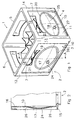
- Fig. 1 shows a diagrammatic, perspective view of an exemplary embodiment of a crate according to the invention.
- Fig. 2 shows a cross section on line A-A in Figure 1,
- Fig. 3 shows a diagrammatic cross section through part of an injection mould for the injection-moulding of the crate shown in Figure 1, and
- Fig. 4 shows an illustration corresponding to Figure 3 in a different position of the mould.
-
- Figure 1 shows an injection-moulded plastic bottle crate 1, having a
rectangular base 2 and having four raisedside walls - The four side walls 3-6 each have a plate-like body which, due to the injection-moulding, is integral with the rest of the crate. In Figure 1, two of these plate-like bodies are clearly visible, namely the plate-
like bodies like bodies corner parts bottom edge 15 which extends along the underside of the crate 1 and atop edge 16 which extends along the top side of the crate 1. - The plate-
like bodies protruding relief reliefs peripheral edge peripheral edges relief planar section like body - A preprinted
label relief edge region label 23, 24 lies in the planar section of the corresponding plate-like body around the outside of therelief - In the cross section shown in Figure 2, and also in Figures 3 and 4, which are yet to be explained, the thickness of the label is exaggerated for the sake of clarity, since, as the person skilled in the art will be aware, labels used for the in-mould labelling technique are usually extremely thin.
- It will also be clear from the illustration shown in Figures 3 and 4 that the
label 24 does not lie on the plate-like body, but rather is embedded therein. In the sketch shown in Figure 2, thelabel 24 appears to rest on the plate-like body, in particular on its planar section, but this appearance results from the exaggerated thickness of the label in the drawing. - It can be clearly seen from Figure 2 that even that part of the relief covered by the label which projects furthest outwards is located further inwards than the outside of the side wall of the crate, so that the label is protected from wear.
- The method for producing the crate described above, in particular that part which is relevant for positioning of the label, will be explained below with reference to Figures 3 and 4.
- Figures 3 and 4 diagrammatically show part of an injection mould for a crate, specifically in cross section through that part which ultimately forms a side wall of the crate, i.e. in fact corresponding to the cross section from Figure 2.
- Figures 3 and 4 show two mould parts of an injection mould used to produce the crate 1, specifically a
first mould part 31 and asecond mould part 32. The first mould part has amould wall 33 which defines the outside of theside wall 3 of the crate 1, only that section of the plate-like body 22 which lies in the area of thelabel 24 being shown in these figures. Thesecond mould part 32 has amould wall 34 which defines the inside of theside wall 3 of the crate 1. - The
mould wall 33 is provided with arecess 35 which corresponds to the desired outer surface of therelief 17 and, around therecess 35, forms a planar peripheral region which defines theplanar section 22 of the plate-like body 10. - A
peripheral groove 36 is formed in themould wall 33 around therecess 35, which peripheral groove serves as a vacuum-application groove and, via one ormore passages 37, is connected to a vacuum source (not shown). Thegroove 37 may, for example, be in the form of a narrow gap, for example with a width of the order of 1/10 millimetre. Such a gap can be obtained if the section containing therecess 35 is designed as an insert in the mould part, and the gap which remains is used as a vacuum-application groove. As an alternative, the groove does not have to be designed as a groove which runs all the way around, but rather as a succession of partial grooves or of vacuum-application holes. - The
mould wall 34 of thesecond mould parts 32 is provided with aprotrusion 38 which substantially corresponds to the shape of therecess 35 in order ultimately to achieve a wall thickness which is as uniform as possible, which is of relevance for cooling of the crate 1 after injection-moulding. - In Figure 3, it can be seen that the size of the preprinted
label 24 is such that it covers the vacuum-application groove 36 in themould wall 33, and the label is held against thefirst mould part 31 as a result of a vacuum being applied in thisgroove 36. Thelabel 24 can be applied by moving thesecond mould part 32 at such a distance away from thefirst mould part 31, or removing it completely, in such a manner that the location for thelabel 24 can be reached by hand or by a mechanical label-positioning device. - As shown in Figure 3, air is enclosed between the
flat label 24 and themould wall 33. - For injection-moulding, the
second mould part 32 is then moved into the desired position with respect to thefirst mould part 31, which position is shown in Figure 4. It is preferable to attempt to make the wall thickness of the plate-like body 10 which is to be formed as uniform as possible. It can be seen that positioning thesecond mould part 32 presses thelabel 24 inwards, towards the recess in thefirst mould part 31. Since thelabel 24 is sufficiently oversized with respect to the vacuum-application groove 36, thelabel 24 continues to cover thisgroove 36 when themould parts label 24 to remain flat even in the position of themould parts - Then, to produce the crate 1, molten plastic is introduced into the injection mould at high pressure. In this process, plastic is introduced into the mould at positions which are such that, in the cavity which ultimately forms the plate-
like body 10, a front of molten plastic moves in, for example indicated by arrow B, which front then, as it were, starting from a peripheral edge of thelabel 24, slides over thelabel 24 when the mould is filled with plastic. In the process, thelabel 24 continues to bear against themould wall 33 against which thelabel 24 had originally been placed. Thus, any air which was enclosed between thelabel 24 and thefirst mould part 31 is pressed out from under thelabel 24 in front of the advancing front of molten plastic. It is important for at least that part of thelabel 24 which spans therecess 35 to form a closed surface, so that it is impossible for any plastic to penetrate between thelabel 24 and themould wall 33. The air which is expelled, or some of this air, could be sucked out via the vacuum-application groove 36. The air can also emerge from under the label and be removed from the mould in some other way. - The
label 24 is (then) pressed taut against therecess 35 in themould part 31 by the front of molten plastic which is moving over it. In Figure 4, the plastic material is indicated by dots. The excess dimensions of thelabel 24 with respect to the vacuum-application groove 36, as well as any slight stretching of the label material, ensure that the vacuum-application groove 36 remains covered by thelabel 24. Surprisingly, thelabel 24, which bears strongly against themould wall 34 only along its peripheral edge, remains in place, while thelabel 24 is nevertheless subjected to a considerable shear load by the molten plastic moving over the label from a peripheral edge. One possible explanation is that the plastic initially flows over a peripheral area of thelabel 24 which bears against the planar part of themould wall 33 and therefore that part is immediately held securely in place by the combination of the vacuum and the pressure from the plastic material. - With the shape of the
relief 17 as described here, it has proven unnecessary to remove the air between thelabel 24 and themould wall 34 before the mould is closed and the molten plastic is injected. This is probably due to the gradual transitions between the parts of the mould wall, in particular, in this slightly double-curved shape, at the relief. - For more extreme forms of relief, however, it may be desirable for the air between label and mould wall to be partially or completely removed in advance in order to avoid air inclusions. This may, inter alia, be achieved by pressing the label against the mould wall by means of a soft, elastic pressure-exerting member, for example a block of foamed plastic or rubber, if appropriate using a robot. The label could also have already been made more or less in the shape of the relief in some other way.
- The film of the
label 24 bonds very strongly to the molten plastic of the crate 1, so that after the plastic has cooled sufficiently the mould can be opened and the crate can be removed, during which process thelabel 24 sticks very well to the plate-like body 10 of theside wall 3. The fact that a peripheral-edge region 26 of thelabel 24 covers the planar section of this plate-like body 10 means that excellent bonding of the label is ensured at least at this location. This also prevents plastic from penetrating between thelabel 24 and themould wall 34 via any small crease in thelabel 24 during the injection of molten plastic. - It will be clear that the shape and location of the
reliefs - In a simple variant, the relief could project inwards with respect to the surrounding planar section of the plate-like body of the side wall of the crate, instead of projecting outwards; a combination of inwards and outwards would also be possible. Also, there may be a plurality of reliefs, covered by one or more preprinted labels, per side wall. By way of example, the reliefs may be letters or letter contours.
Claims (12)
- Injection-moulded plastic crate (1), comprising a base (2) and raised side walls (3-6) which are connected to one another at the corners of the crate, the crate being provided with at least one handle (7) for carrying the crate, and at least one of the side walls (3-6) comprising a plate-like body (10, 11) which is made from plastic and on the outside of which a preprinted label (24, 25) made from plastic film is arranged by placing the preprinted label - before molten plastic is introduced into a suitable injection mould - at the intended location in the injection mould and then securing it at this location, wherein the label forms a strong bond with the plastic material of the crate, characterized in that the plate-like body (10, 11) of the side wall (3, 4), in an area which is covered by the preprinted label (24, 25), has a relief (17, 18) with respect to the plane of the side wall (3, 4).
- Crate according to claim 1, in which the plate-like body (10, 11) of the side wall is substantially planar (21, 22) where it is covered by a peripheral-edge region (26, 27), which extends along the periphery, of the label (24, 25).
- Crate according to claim 1 or 2, in which the relief (17, 18) forms a double-curved and substantially smooth surface.
- Crate according to one or more of the preceding claims, in which the relief projects outwards with respect to the planar part (21, 22) of the plate-like body (10, 11), and in which the side wall in question is also provided with integral protective components (12, 13, 14, 15, 16), in particular a protective edge which lies at a distance around the relief, which protective components project outwards beyond the relief.
- Crate according to one or more of the preceding claims, in which the crate has a rectangular base (2) and four side walls (3-6), which each have a plate-like body which lies further inwards than the outside of the corner parts (12, 13, 14) of the crate, a bottom edge (15) which extends along the underside of the crate, and a top edge (16) which extends along the top side of the crate, each plate-like body (10, 11) being provided with a double-curved, outwardly protruding relief (17, 18) with an oval peripheral edge (19, 20) which forms the transition to the planar section of the plate-like body, with a preprinted label (24, 25) over each relief, a peripheral-edge region (26, 27) of which label lies over the planar section of the plate-like body around the outside of the relief.
- Crate according to one or more of the preceding claims, in which the plate-like body (10, 11) is of substantially uniform thickness.
- Crate according to one or more of the preceding claims, in which at least two side walls which lie opposite one another are provided with a handle opening (7).
- Crate according to one or more of the preceding claims, in which the crate (1) is a bottle crate and a compartment divider is arranged in the crate.
- Method for producing a crate according to one or more of the preceding claims, comprising the use of a suitable injection mould having a first mould part (31), a mould wall (34) of which is provided with a recess (35) corresponding to the outer surface of the relief (17), around which relief (35) the mould wall forms a planar peripheral-edge region, an encircling vacuum-application groove (36) being formed in the planar peripheral-edge area, which groove is connected, via one or more associated passages (37), to an actuable vacuum source, and having a second mould part (32) which can move with respect to the first mould part (31) and, in an injection-moulding position, together with the first mould part delimits a plate-shaped cavity which corresponds to the shape of the plate-like body (10) of the side wall (3) of the crate which is to be formed, the method comprising the following steps:arranging a preprinted label (24) made from plastic film against the mould wall (34) which is provided with the recess (35), in such a manner that a peripheral-edge region (26) of the label bears against the planar section of the mould wall and covers the vacuum-application groove (36),moving the first and second mould parts (31, 32) into the injection-moulding position, so that a plate-shaped space is delimited between the first and second mould parts,injecting molten plastic into the injection mould, in such a manner that the plastic flowing into the plate-shaped space flows over the label (24) from a peripheral edge and displaces any air which is present between the preprinted label (24) and the mould wall, in which case the label (24) presses against the mould wall (33) which is provided with a recess (35).
- Method according to claim 9, in which the mould wall (34) is only provided with the encircling vacuum-application groove (36) and is closed in the region of the recess (35) therein, which forms the relief.
- Method according to claim 9 or 10, in which the preprinted label is positioned with the aid of an elastically compressible positioning body which has a holding surface for holding a preprinted label which is to be positioned, which positioning body presses the preprinted label against the mould wall, including its wall section which delimits the recess, the positioning body undergoing elastic deformation, in such a manner that the label bears against the mould wall over substantially its entire surface, after which a vacuum is applied via the vacuum-application groove.
- Method according to one or more of claims 9-11, in which the molten plastic is injected into the injection mould outside the plate-shaped space between the first and second mould parts (31, 32), and preferably the injection takes place in that part of the mould which forms the base of the crate, in such a manner that the molten plastic flows over the preprinted label (24) from one side.
Applications Claiming Priority (2)
| Application Number | Priority Date | Filing Date | Title |
|---|---|---|---|
| NL1010605 | 1998-11-20 | ||
| NL1010605A NL1010605C2 (en) | 1998-11-20 | 1998-11-20 | Plastic crate manufactured by injection molding. |
Publications (2)
| Publication Number | Publication Date |
|---|---|
| EP1008527A1 true EP1008527A1 (en) | 2000-06-14 |
| EP1008527B1 EP1008527B1 (en) | 2003-06-11 |
Family
ID=19768173
Family Applications (1)
| Application Number | Title | Priority Date | Filing Date |
|---|---|---|---|
| EP99203748A Revoked EP1008527B1 (en) | 1998-11-20 | 1999-11-09 | Injection moulded plastic crate |
Country Status (4)
| Country | Link |
|---|---|
| EP (1) | EP1008527B1 (en) |
| AT (1) | ATE242731T1 (en) |
| DE (1) | DE69908740T2 (en) |
| NL (1) | NL1010605C2 (en) |
Cited By (21)
| Publication number | Priority date | Publication date | Assignee | Title |
|---|---|---|---|---|
| EP1226914A1 (en) * | 2001-01-30 | 2002-07-31 | An der Heiden, Dominik | Method for producing plastic parts |
| EP1233135A1 (en) * | 2001-01-30 | 2002-08-21 | An der Heiden, Dominik | Method for producing a plastic part with a frame |
| USD465417S1 (en) | 2001-04-16 | 2002-11-12 | Rehrig Pacific Company | Stackable low depth tray |
| USD466018S1 (en) | 2001-06-25 | 2002-11-26 | Rehrig Pacific Company | Stackable low depth tray |
| WO2003011555A1 (en) * | 2001-07-23 | 2003-02-13 | Bayer Aktiengesellschaft | Method for in-mold lamination of foils |
| DE10352654A1 (en) * | 2003-11-11 | 2005-06-16 | Linpac Materials Handling(Germany)Gmbh | Plastic crate for bottles has walls consisting of frame made up of side columns and cross-bars, transparent sheet being fitted inside frame which has picture of contents of crate printed on its reverse side |
| NL1028510C2 (en) * | 2005-03-10 | 2006-09-12 | Ecim Technologies Bv | Plastic product with stiffeners and method for their manufacture. |
| EP1710069A2 (en) * | 2005-04-04 | 2006-10-11 | D.W. Plastics N.V. | In-mould label protection |
| GB2428402A (en) * | 2005-07-19 | 2007-01-31 | Arjobex Sas | Moulded, labelled plastic article with a relief pattern. |
| EP2554485A1 (en) * | 2011-08-02 | 2013-02-06 | Oberland M & V GmbH | Bottle crate with embossing foil |
| CN102963134A (en) * | 2011-09-01 | 2013-03-13 | 克朗斯股份公司 | Container with printed surface contour and printing method |
| EP2700582A1 (en) * | 2008-07-04 | 2014-02-26 | DW Plastics N.V. | Container provided with markings |
| DE102013014197A1 (en) * | 2013-08-23 | 2015-02-26 | Schoeller Arca Systems Gmbh | Method for the delivery and return of crates and crates equipped therefor |
| US9682808B2 (en) | 2001-04-16 | 2017-06-20 | Rehrig Pacific Company | Stackable low depth tray |
| USD831962S1 (en) | 2017-12-22 | 2018-10-30 | Rehrig Pacific Company | Beverage crate |
| EP3517453A1 (en) * | 2011-11-08 | 2019-07-31 | Störtebeker Braumanufaktur GmbH | Method for manufacturing beverage crates from plastic |
| US10377529B2 (en) | 2008-10-06 | 2019-08-13 | Rehrig Pacific Company | Stackable low depth tray |
| EP3771543A1 (en) * | 2019-07-31 | 2021-02-03 | PakPot Pty Ltd | Method of applying a label to a container, a container produced by said method, and an injection mould for producing a labelled container |
| US11319130B2 (en) | 2014-12-04 | 2022-05-03 | Rehrig Pacific Company | Beverage crate |
| US11390415B2 (en) | 2018-10-25 | 2022-07-19 | Rehrig Pacific Company | Nestable bottle crate |
| EP4194351A1 (en) * | 2021-12-07 | 2023-06-14 | Oberland M & V GmbH | Method of manufacturing a transport container, injection mould for such a container and transport container with inmould foil |
Families Citing this family (7)
| Publication number | Priority date | Publication date | Assignee | Title |
|---|---|---|---|---|
| US8893891B2 (en) | 2008-03-31 | 2014-11-25 | Rehrig Pacific Company | Stackable low depth tray |
| DE102008032106A1 (en) * | 2008-07-08 | 2010-01-14 | Schoeller Arca Systems Gmbh | Plastic box with a relief |
| US8353402B2 (en) | 2008-10-06 | 2013-01-15 | Rehrig Pacific Company | Stackable low depth tray |
| US8636142B2 (en) | 2009-09-10 | 2014-01-28 | Rehrig Pacific Company | Stackable low depth tray |
| US8109408B2 (en) | 2009-11-16 | 2012-02-07 | Rehrig Pacific Company | Low depth crate |
| DE102011103824B4 (en) | 2011-06-01 | 2024-02-01 | Leonhard Kurz Stiftung & Co. Kg | Process for producing in-mold decorated plastic moldings |
| DE102014105651A1 (en) | 2014-04-22 | 2015-11-05 | Schoeller Allibert Gmbh | Hot stamping on bottle case |
Citations (3)
| Publication number | Priority date | Publication date | Assignee | Title |
|---|---|---|---|---|
| NL7908382A (en) * | 1979-11-16 | 1981-06-16 | Seven Up Nederland B V | Bottle crate marking system - snaps plastic plates behind protrusions on adjacent parallel external ribs |
| GB2185708A (en) | 1986-01-23 | 1987-07-29 | Cerbo Ab | Positioning inserts in moulds |
| DE19613494A1 (en) | 1996-04-04 | 1997-10-09 | Theysohn Friedrich Fa | Identification for moulded box used for carriage of bottles or bags |
-
1998
- 1998-11-20 NL NL1010605A patent/NL1010605C2/en not_active IP Right Cessation
-
1999
- 1999-11-09 EP EP99203748A patent/EP1008527B1/en not_active Revoked
- 1999-11-09 AT AT99203748T patent/ATE242731T1/en not_active IP Right Cessation
- 1999-11-09 DE DE69908740T patent/DE69908740T2/en not_active Revoked
Patent Citations (3)
| Publication number | Priority date | Publication date | Assignee | Title |
|---|---|---|---|---|
| NL7908382A (en) * | 1979-11-16 | 1981-06-16 | Seven Up Nederland B V | Bottle crate marking system - snaps plastic plates behind protrusions on adjacent parallel external ribs |
| GB2185708A (en) | 1986-01-23 | 1987-07-29 | Cerbo Ab | Positioning inserts in moulds |
| DE19613494A1 (en) | 1996-04-04 | 1997-10-09 | Theysohn Friedrich Fa | Identification for moulded box used for carriage of bottles or bags |
Cited By (32)
| Publication number | Priority date | Publication date | Assignee | Title |
|---|---|---|---|---|
| EP1226914A1 (en) * | 2001-01-30 | 2002-07-31 | An der Heiden, Dominik | Method for producing plastic parts |
| EP1233135A1 (en) * | 2001-01-30 | 2002-08-21 | An der Heiden, Dominik | Method for producing a plastic part with a frame |
| USD465417S1 (en) | 2001-04-16 | 2002-11-12 | Rehrig Pacific Company | Stackable low depth tray |
| US9682808B2 (en) | 2001-04-16 | 2017-06-20 | Rehrig Pacific Company | Stackable low depth tray |
| USD466018S1 (en) | 2001-06-25 | 2002-11-26 | Rehrig Pacific Company | Stackable low depth tray |
| USD494867S1 (en) | 2001-06-25 | 2004-08-24 | Rehrig Pacific Company | Stackable low depth tray |
| WO2003011555A1 (en) * | 2001-07-23 | 2003-02-13 | Bayer Aktiengesellschaft | Method for in-mold lamination of foils |
| US7276197B2 (en) | 2001-07-23 | 2007-10-02 | Bayer Materialscience Ag | Method for in-mold lamination of foils |
| DE10352654A1 (en) * | 2003-11-11 | 2005-06-16 | Linpac Materials Handling(Germany)Gmbh | Plastic crate for bottles has walls consisting of frame made up of side columns and cross-bars, transparent sheet being fitted inside frame which has picture of contents of crate printed on its reverse side |
| WO2006096057A1 (en) * | 2005-03-10 | 2006-09-14 | Ecim Technologies B.V. | Plastic product with stiffening provisions, and method for manufacturing same |
| NL1028510C2 (en) * | 2005-03-10 | 2006-09-12 | Ecim Technologies Bv | Plastic product with stiffeners and method for their manufacture. |
| EP1710069A2 (en) * | 2005-04-04 | 2006-10-11 | D.W. Plastics N.V. | In-mould label protection |
| EP1710069A3 (en) * | 2005-04-04 | 2007-06-27 | D.W. Plastics N.V. | In-mould label protection |
| GB2428402A (en) * | 2005-07-19 | 2007-01-31 | Arjobex Sas | Moulded, labelled plastic article with a relief pattern. |
| EP2700582A1 (en) * | 2008-07-04 | 2014-02-26 | DW Plastics N.V. | Container provided with markings |
| US10377529B2 (en) | 2008-10-06 | 2019-08-13 | Rehrig Pacific Company | Stackable low depth tray |
| DE102011109108B4 (en) | 2011-08-02 | 2022-11-17 | Oberland M & V Gmbh | Bottle crate with stamping foil |
| EP2554485B1 (en) | 2011-08-02 | 2015-08-12 | Oberland M & V GmbH | Bottle crate with embossing foil |
| EP2554485A1 (en) * | 2011-08-02 | 2013-02-06 | Oberland M & V GmbH | Bottle crate with embossing foil |
| CN102963134A (en) * | 2011-09-01 | 2013-03-13 | 克朗斯股份公司 | Container with printed surface contour and printing method |
| CN102963134B (en) * | 2011-09-01 | 2016-03-02 | 克朗斯股份公司 | There is container and the printing process of the surface profile of printing |
| EP3524531B1 (en) | 2011-11-08 | 2020-07-08 | Störtebeker Braumanufaktur GmbH | Method for manufacturing beverage crates from plastic |
| EP3517453A1 (en) * | 2011-11-08 | 2019-07-31 | Störtebeker Braumanufaktur GmbH | Method for manufacturing beverage crates from plastic |
| EP3524531A1 (en) * | 2011-11-08 | 2019-08-14 | Störtebeker Braumanufaktur GmbH | Method for manufacturing beverage crates from plastic |
| EP2776324B1 (en) * | 2011-11-08 | 2021-10-13 | Störtebeker Braumanufaktur GmbH | Method for manufacturing beverage crates from plastic |
| EP3517453B1 (en) | 2011-11-08 | 2021-10-13 | Störtebeker Braumanufaktur GmbH | Method for manufacturing beverage crates from plastic |
| DE102013014197A1 (en) * | 2013-08-23 | 2015-02-26 | Schoeller Arca Systems Gmbh | Method for the delivery and return of crates and crates equipped therefor |
| US11319130B2 (en) | 2014-12-04 | 2022-05-03 | Rehrig Pacific Company | Beverage crate |
| USD831962S1 (en) | 2017-12-22 | 2018-10-30 | Rehrig Pacific Company | Beverage crate |
| US11390415B2 (en) | 2018-10-25 | 2022-07-19 | Rehrig Pacific Company | Nestable bottle crate |
| EP3771543A1 (en) * | 2019-07-31 | 2021-02-03 | PakPot Pty Ltd | Method of applying a label to a container, a container produced by said method, and an injection mould for producing a labelled container |
| EP4194351A1 (en) * | 2021-12-07 | 2023-06-14 | Oberland M & V GmbH | Method of manufacturing a transport container, injection mould for such a container and transport container with inmould foil |
Also Published As
| Publication number | Publication date |
|---|---|
| NL1010605C2 (en) | 2000-05-23 |
| EP1008527B1 (en) | 2003-06-11 |
| DE69908740T2 (en) | 2004-04-29 |
| ATE242731T1 (en) | 2003-06-15 |
| DE69908740D1 (en) | 2003-07-17 |
Similar Documents
| Publication | Publication Date | Title |
|---|---|---|
| EP1008527B1 (en) | Injection moulded plastic crate | |
| US7140857B2 (en) | Label ledge for injection molded containers | |
| US6280823B1 (en) | Foil-covered plastic part and method of making same | |
| WO2001000493A1 (en) | Plastic container for the transportation and/or storage of goods | |
| AU630166B2 (en) | Label and method for in-mold molding using a label thereof | |
| US20180147761A1 (en) | Composite structure of toughened glass and plastic and manufacturing method thereof | |
| JP2003011213A (en) | Molding system and method using injection mold with side gate along with vacuum aid and injection blow molded article obtained using the same | |
| US5633022A (en) | Differential temperature vacuum-forming tool | |
| US6132834A (en) | Plastic article comprising a molded body and an inlaid decorative element and method of manufacture of said plastic article | |
| JP3977012B2 (en) | Container with undercut and blow mold suitable for molding the container | |
| EP1625925A2 (en) | Moulded article and method of manufacture | |
| US20150024156A1 (en) | In-mold label forming surfaces for molded articles | |
| US20020178628A1 (en) | Three-dimensional label for a container and method of forming the same | |
| IL116394A (en) | Method for producing containers such as bottles or the like with film of thermoplastic synthetic material and apparatus for carrying out the method | |
| EP1710069A2 (en) | In-mould label protection | |
| JP2002154152A (en) | In-mold label and container with in-mold label | |
| KR102005884B1 (en) | Logo label manufacturing method of logo label thereof | |
| JPH0891416A (en) | Cover body with spoon and production thereof | |
| EP2700582B1 (en) | Container provided with markings | |
| KR20020023288A (en) | Method of manufacturing solid label of silicon resin | |
| EP1153728B1 (en) | Method for producing a thermo plastic container with a printed surface portion | |
| JP4145480B2 (en) | Container with punching label | |
| JPS63135213A (en) | Manufacture of decorative molding | |
| KR100342022B1 (en) | Method for forming injection molding product taking many projection | |
| JP4045202B2 (en) | Molded resin molding |
Legal Events
| Date | Code | Title | Description |
|---|---|---|---|
| PUAI | Public reference made under article 153(3) epc to a published international application that has entered the european phase |
Free format text: ORIGINAL CODE: 0009012 |
|
| AK | Designated contracting states |
Kind code of ref document: A1 Designated state(s): AT BE CH CY DE DK ES FI FR GB GR IE IT LI LU MC NL PT SE |
|
| AX | Request for extension of the european patent |
Free format text: AL;LT;LV;MK;RO;SI |
|
| 17P | Request for examination filed |
Effective date: 20000731 |
|
| AKX | Designation fees paid |
Free format text: AT BE CH CY DE DK ES FI FR GB GR IE IT LI LU MC NL PT SE |
|
| RAP1 | Party data changed (applicant data changed or rights of an application transferred) |
Owner name: SCHOELLER WAVIN SYSTEMS N.V. |
|
| GRAH | Despatch of communication of intention to grant a patent |
Free format text: ORIGINAL CODE: EPIDOS IGRA |
|
| GRAH | Despatch of communication of intention to grant a patent |
Free format text: ORIGINAL CODE: EPIDOS IGRA |
|
| GRAA | (expected) grant |
Free format text: ORIGINAL CODE: 0009210 |
|
| AK | Designated contracting states |
Designated state(s): AT BE CH CY DE DK ES FI FR GB GR IE IT LI LU MC NL PT SE |
|
| PG25 | Lapsed in a contracting state [announced via postgrant information from national office to epo] |
Ref country code: LI Free format text: LAPSE BECAUSE OF FAILURE TO SUBMIT A TRANSLATION OF THE DESCRIPTION OR TO PAY THE FEE WITHIN THE PRESCRIBED TIME-LIMIT Effective date: 20030611 Ref country code: IT Free format text: LAPSE BECAUSE OF FAILURE TO SUBMIT A TRANSLATION OF THE DESCRIPTION OR TO PAY THE FEE WITHIN THE PRESCRIBED TIME-LIMIT;WARNING: LAPSES OF ITALIAN PATENTS WITH EFFECTIVE DATE BEFORE 2007 MAY HAVE OCCURRED AT ANY TIME BEFORE 2007. THE CORRECT EFFECTIVE DATE MAY BE DIFFERENT FROM THE ONE RECORDED. Effective date: 20030611 Ref country code: FR Free format text: LAPSE BECAUSE OF FAILURE TO SUBMIT A TRANSLATION OF THE DESCRIPTION OR TO PAY THE FEE WITHIN THE PRESCRIBED TIME-LIMIT Effective date: 20030611 Ref country code: FI Free format text: LAPSE BECAUSE OF FAILURE TO SUBMIT A TRANSLATION OF THE DESCRIPTION OR TO PAY THE FEE WITHIN THE PRESCRIBED TIME-LIMIT Effective date: 20030611 Ref country code: CH Free format text: LAPSE BECAUSE OF FAILURE TO SUBMIT A TRANSLATION OF THE DESCRIPTION OR TO PAY THE FEE WITHIN THE PRESCRIBED TIME-LIMIT Effective date: 20030611 Ref country code: AT Free format text: LAPSE BECAUSE OF FAILURE TO SUBMIT A TRANSLATION OF THE DESCRIPTION OR TO PAY THE FEE WITHIN THE PRESCRIBED TIME-LIMIT Effective date: 20030611 |
|
| REG | Reference to a national code |
Ref country code: GB Ref legal event code: FG4D |
|
| REG | Reference to a national code |
Ref country code: CH Ref legal event code: EP |
|
| REG | Reference to a national code |
Ref country code: IE Ref legal event code: FG4D |
|
| REF | Corresponds to: |
Ref document number: 69908740 Country of ref document: DE Date of ref document: 20030717 Kind code of ref document: P |
|
| PG25 | Lapsed in a contracting state [announced via postgrant information from national office to epo] |
Ref country code: SE Free format text: LAPSE BECAUSE OF FAILURE TO SUBMIT A TRANSLATION OF THE DESCRIPTION OR TO PAY THE FEE WITHIN THE PRESCRIBED TIME-LIMIT Effective date: 20030911 Ref country code: PT Free format text: LAPSE BECAUSE OF FAILURE TO SUBMIT A TRANSLATION OF THE DESCRIPTION OR TO PAY THE FEE WITHIN THE PRESCRIBED TIME-LIMIT Effective date: 20030911 Ref country code: GR Free format text: LAPSE BECAUSE OF FAILURE TO SUBMIT A TRANSLATION OF THE DESCRIPTION OR TO PAY THE FEE WITHIN THE PRESCRIBED TIME-LIMIT Effective date: 20030911 Ref country code: DK Free format text: LAPSE BECAUSE OF FAILURE TO SUBMIT A TRANSLATION OF THE DESCRIPTION OR TO PAY THE FEE WITHIN THE PRESCRIBED TIME-LIMIT Effective date: 20030911 |
|
| PG25 | Lapsed in a contracting state [announced via postgrant information from national office to epo] |
Ref country code: ES Free format text: LAPSE BECAUSE OF FAILURE TO SUBMIT A TRANSLATION OF THE DESCRIPTION OR TO PAY THE FEE WITHIN THE PRESCRIBED TIME-LIMIT Effective date: 20030922 |
|
| PG25 | Lapsed in a contracting state [announced via postgrant information from national office to epo] |
Ref country code: LU Free format text: LAPSE BECAUSE OF NON-PAYMENT OF DUE FEES Effective date: 20031109 Ref country code: GB Free format text: LAPSE BECAUSE OF NON-PAYMENT OF DUE FEES Effective date: 20031109 Ref country code: CY Free format text: LAPSE BECAUSE OF FAILURE TO SUBMIT A TRANSLATION OF THE DESCRIPTION OR TO PAY THE FEE WITHIN THE PRESCRIBED TIME-LIMIT Effective date: 20031109 |
|
| PG25 | Lapsed in a contracting state [announced via postgrant information from national office to epo] |
Ref country code: IE Free format text: LAPSE BECAUSE OF NON-PAYMENT OF DUE FEES Effective date: 20031110 |
|
| PG25 | Lapsed in a contracting state [announced via postgrant information from national office to epo] |
Ref country code: MC Free format text: LAPSE BECAUSE OF NON-PAYMENT OF DUE FEES Effective date: 20031130 |
|
| REG | Reference to a national code |
Ref country code: CH Ref legal event code: PL |
|
| PLBQ | Unpublished change to opponent data |
Free format text: ORIGINAL CODE: EPIDOS OPPO |
|
| PLBI | Opposition filed |
Free format text: ORIGINAL CODE: 0009260 |
|
| PLAX | Notice of opposition and request to file observation + time limit sent |
Free format text: ORIGINAL CODE: EPIDOSNOBS2 |
|
| 26 | Opposition filed |
Opponent name: D W PLASTICS N.V. Effective date: 20040310 |
|
| EN | Fr: translation not filed | ||
| GBPC | Gb: european patent ceased through non-payment of renewal fee |
Effective date: 20031109 |
|
| NLR1 | Nl: opposition has been filed with the epo |
Opponent name: D W PLASTICS N.V. |
|
| REG | Reference to a national code |
Ref country code: IE Ref legal event code: MM4A |
|
| PLBB | Reply of patent proprietor to notice(s) of opposition received |
Free format text: ORIGINAL CODE: EPIDOSNOBS3 |
|
| PGFP | Annual fee paid to national office [announced via postgrant information from national office to epo] |
Ref country code: DE Payment date: 20050125 Year of fee payment: 6 |
|
| RDAF | Communication despatched that patent is revoked |
Free format text: ORIGINAL CODE: EPIDOSNREV1 |
|
| PGFP | Annual fee paid to national office [announced via postgrant information from national office to epo] |
Ref country code: NL Payment date: 20051117 Year of fee payment: 7 |
|
| PGFP | Annual fee paid to national office [announced via postgrant information from national office to epo] |
Ref country code: BE Payment date: 20051123 Year of fee payment: 7 |
|
| RDAG | Patent revoked |
Free format text: ORIGINAL CODE: 0009271 |
|
| STAA | Information on the status of an ep patent application or granted ep patent |
Free format text: STATUS: PATENT REVOKED |
|
| 27W | Patent revoked |
Effective date: 20051030 |
|
| NLR2 | Nl: decision of opposition |
Effective date: 20051030 |
|
| PLAB | Opposition data, opponent's data or that of the opponent's representative modified |
Free format text: ORIGINAL CODE: 0009299OPPO |