EP1008108B1 - 2-d gittergeometrie und bewegungsvektorkompression - Google Patents
2-d gittergeometrie und bewegungsvektorkompression Download PDFInfo
- Publication number
- EP1008108B1 EP1008108B1 EP97947938A EP97947938A EP1008108B1 EP 1008108 B1 EP1008108 B1 EP 1008108B1 EP 97947938 A EP97947938 A EP 97947938A EP 97947938 A EP97947938 A EP 97947938A EP 1008108 B1 EP1008108 B1 EP 1008108B1
- Authority
- EP
- European Patent Office
- Prior art keywords
- mesh
- node
- motion vector
- encoding
- decoding
- Prior art date
- Legal status (The legal status is an assumption and is not a legal conclusion. Google has not performed a legal analysis and makes no representation as to the accuracy of the status listed.)
- Expired - Lifetime
Links
Images


Classifications
-
- G—PHYSICS
- G06—COMPUTING; CALCULATING OR COUNTING
- G06T—IMAGE DATA PROCESSING OR GENERATION, IN GENERAL
- G06T9/00—Image coding
- G06T9/001—Model-based coding, e.g. wire frame
-
- H—ELECTRICITY
- H04—ELECTRIC COMMUNICATION TECHNIQUE
- H04N—PICTORIAL COMMUNICATION, e.g. TELEVISION
- H04N19/00—Methods or arrangements for coding, decoding, compressing or decompressing digital video signals
- H04N19/46—Embedding additional information in the video signal during the compression process
-
- H—ELECTRICITY
- H04—ELECTRIC COMMUNICATION TECHNIQUE
- H04N—PICTORIAL COMMUNICATION, e.g. TELEVISION
- H04N19/00—Methods or arrangements for coding, decoding, compressing or decompressing digital video signals
- H04N19/50—Methods or arrangements for coding, decoding, compressing or decompressing digital video signals using predictive coding
- H04N19/503—Methods or arrangements for coding, decoding, compressing or decompressing digital video signals using predictive coding involving temporal prediction
- H04N19/51—Motion estimation or motion compensation
- H04N19/513—Processing of motion vectors
- H04N19/517—Processing of motion vectors by encoding
-
- H—ELECTRICITY
- H04—ELECTRIC COMMUNICATION TECHNIQUE
- H04N—PICTORIAL COMMUNICATION, e.g. TELEVISION
- H04N19/00—Methods or arrangements for coding, decoding, compressing or decompressing digital video signals
- H04N19/50—Methods or arrangements for coding, decoding, compressing or decompressing digital video signals using predictive coding
- H04N19/503—Methods or arrangements for coding, decoding, compressing or decompressing digital video signals using predictive coding involving temporal prediction
- H04N19/51—Motion estimation or motion compensation
- H04N19/537—Motion estimation other than block-based
- H04N19/54—Motion estimation other than block-based using feature points or meshes
-
- H—ELECTRICITY
- H04—ELECTRIC COMMUNICATION TECHNIQUE
- H04N—PICTORIAL COMMUNICATION, e.g. TELEVISION
- H04N19/00—Methods or arrangements for coding, decoding, compressing or decompressing digital video signals
- H04N19/50—Methods or arrangements for coding, decoding, compressing or decompressing digital video signals using predictive coding
- H04N19/593—Methods or arrangements for coding, decoding, compressing or decompressing digital video signals using predictive coding involving spatial prediction techniques
Definitions
- This invention is in the field of coding and manipulation of images, and specifically, the coding of sequences of 2D meshes, generally corresponding to a sequence of images.
- a 2D triangular mesh refers to a tessellation of a 2D visual object plane into triangular patches.
- the vertices of the triangular patches are called “node points.”
- the straight-line segments joining the node points are called “edges.”
- a dynamic 2D mesh consists of a temporal sequence of 2D triangular meshes, where each mesh has the same topology (i.e., structure), but node positions may differ from one mesh to the next.
- a dynamic 2D mesh may be defined by the geometry of the initial 2D mesh and motion vectors at the node points for subsequent meshes, where each motion vector points from a node point of the previous mesh in the sequence to a node point of the current mesh.
- the dynamic 2D mesh may be used to create 2D animations by mapping texture from a Still image onto successive 2D meshes via well-known texture mapping methods.
- the dynamic mesh may be used to render a waving flag from a still image of a flag.
- the local deformations of the texture in time are captured by the motion of mesh nodes from one mesh to the next Hence, different animations of the same texture may be achieved by different sets of node motion vectors.
- Texture mapping utilizes the structure of the mesh, i.e., the way the nodes of the mesh are connected with each other, namely the configuration of the edges of the mesh.
- a mesh may have a specified implicit structure, such as uniform structure or Delaunay structure, as described in S. M. Omohundro, "The Delaunay triangulation and function learning," International Computer Science Institute Technical Report TR-90-001, University of California Berkeley, January 1990.
- Efficient coding of an animation sequence may be achieved by separately coding the still image texture, and the associated 2D mesh, i.e., the geometry and node vectors.
- the associated 2D mesh is represented by the geometry of the first mesh and motion vectors of the nodes of this first and subsequent meshes.
- the 2D mesh is encoded by coding the geometry of the first mesh and motion vectors of the nodes of this first and subsequent meshes.
- the mesh geometry compression technique described here is limited to 2D triangular meshes with implicit topology, specifically meshes with uniform and Delaunay topology.
- the mesh topology is defined implicitly, given the locations of the mesh nodes (also called vertices) and some additional information to be specified in detail later.
- Algorithms to implement Delaunay triangulations are available in literature and are not described here. It should be noted that Delaunay triangulations are uniquely defined except if the nodes to be triangulated contain certain degeneracies in their locations.
- both the mesh encoder and decoder use an agreed upon technique to handle such degeneracies. Such techniques are well known to those of skill in the art.
- the mesh geometry compression technique described here allows a high compression ratio for these constrained classes of meshes.
- MPEG-4 is an object-based multimedia compression standard being developed by the Motion Picture Experts Group, which allows for encoding of different audio-visual objects (AVO) in the scene separately, as an extension of the previous MPEG-1/2 standards. These AVO are decoded and then composited at the user terminal according to a transmitted scene description script and/or user interaction to form display frames.
- the visual objects may have natural or synthetic content, including audio, video, 3D graphics models, scrolling text and graphics overlay, and so on.
- This invention comprises methods for encoding the mesh data into a compressed format and methods for decoding the compressed format.
- the use of a compressed format facilitates efficient storage and communication of the mesh data.
- the coding methods described are lossless, i.e. the compressed format represents the same information contained in the original mesh data. At the same time, use of the compressed format reduces the amount of storage space or communication bandwidth required.
- An object of the invention is to provide a system and method for encoding and decoding the mesh and displacement of the node points from one frame time instant to the next.
- Modeling and estimating the motion of objects in a sequence of image frames is common in video processing and has a variety of applications.
- a common approach is block-based motion modeling, where motion parameters are estimated for each square block of pixels independently.
- the translational block motion model has proven satisfactory for video compression; and has been adopted in international standards such as MPEG-1, -2 and -4.
- 2D mesh-based motion modeling has been proposed as a promising alternative in video processing to block-based motion modeling.
- a 2D mesh is a tessellation (or partition) of a 2D planar region into polygonal patches.
- the vertices of the polygonal patches are referred to as the node points of the mesh.
- the patches are usually triangles or quadrangles, leading to triangular or quadrilateral meshes, respectively. See Fig. 1a.
- a 2D mesh is associated with an image or a set of images, such that the polygonal mesh patches correspond to patches of texture in the images, where the texture consists of the image pixels inside a patch.
- Polygonal patches in a reference frame are deformed by the movements of the node points into polygonal patches in another frame, and the texture inside each patch in the reference frame is warped onto the other frame using a parametric mapping as a function of the node point motion vectors. See Figs. 1b and 1c.
- affine mapping is-used, which may model translation, rotation, scaling and shear. Note that, in mesh-based motion modeling, the patches do not overlap in the reference frame or in the current frame.
- a statement that two triangles are adjacent means that they share a common edge.
- an affine transform can guarantee the continuity of the mapping across the boundaries of adjacent triangles. This implies that the original 2D motion field may be compactly represented by the motion of the node points, from which a continuous, piece-wise affine motion field can be reconstructed.
- 3D polygon meshes have long been used for efficient 3D object geometry modeling and rendering in computer graphics. Equations similar to parametric mappings used in mesh-based motion modeling have also been used in 3D graphics to perform texture mapping, a popular procedure to render natural images on polygon meshes describing graphic objects for photo-realistic synthesized images. Texture mapping in 3D graphics is realized by assigning a texture coordinate (a pixel position on a 2D image) to every 3D node point on the polygonal mesh. Thus, each polygonal surface element on the 3D mesh is associated with a patch of the 2D image, which is then rendered on the polygon mesh subject to proper warping transformation. An animation may be created by rendering the same image onto a deforming mesh repeatedly. A similar process may be performed with 2D meshes to render an animated image sequence from an image and corresponding deforming meshes.
- Determining the motion of 2D meshes from a given image sequence is performed by estimating the motion of mesh node points over time.
- motion estimation refers to searching in a given reference image for the best locations of the node points, such that the triangular image patches in the reference frame optimally match those in the current image.
- the mesh in the initial reference image may have a regular structure, in which case it is called a uniform mesh, or it may be adapted to the image, in which case it is called a content-based mesh.
- a description of an algorithm for content-based (adaptive) mesh design may be found in the literature.
- node motion vector search from one frame to the next.
- the simplest method is to form blocks that are centered around the node points and then use a gradient-based technique or block-matching to find motion vectors at the location of the nodes.
- Hexagonal matching and closed-form matching techniques find the optimal motion vector at each node under the parametric warping of all patches surrounding the node while enforcing mesh connectivity constraints.
- Another method is iterative gradient-based optimization of node point locations, taking into account image features and mesh deformation criteria.
- an image object 10 is depicted.
- the motion of nodes, such as nodes 12, 14, from an image object 10 is described as the image object is transformed into an animated image object 16, having nodes 12a, 14a.
- the motion of nodes describe local motion and deformation of image object 10 over which a mesh 18 is imposed.
- the transformation that takes the mesh of object 16 to image object 10 results in local motion and deformation as well as a scaling of the entire image object
- an object of this invention is to provide a method for encoding and decoding the mesh and displacement of the node points from one frame time instant to the next.
- the texture to be animated may be encoded using a still image coding method, such as those used in MPEG-4 (Moving Picture Experts Group Standard 4).
- the texture to be animated may be a still image of a natural object or it may be a synthetic (computer generated) image.
- the application at the decoder decodes the texture and the mesh and renders the animation.
- the current version of MPEG-4 Systems Working Draft (WD) specify a framework for applications that support animation, MPEG-4 Systems Working Draft V 5.0 of ISO/IEC 14496, Document No. N1825, July 1997, hereinafter MPEG-4 WD V 5.0).
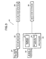
- Subsystem 20 includes a texture encoder 22, which receives still image texture data, 24, and generates a texture coded bit stream, 26.
- a mesh encoder 28 receives a 2D mesh sequence 30.
- Encoder 28 includes a geometry encoder 32 and a motion vector encoder 34. Encoder 28 generates a mesh coded bit stream 36.
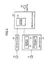
- the decoding subsystem 20 is shown in Fig. 4, and includes a texture decoder 38 and a mesh decoder 40.
- Mesh decoder 40 includes a geometry decoder 42 and a motion vector decoder 44.
- Output from texture decoder 38 and mesh decoder 40 results in texture mapping data 46, which is used in an animation application 48, resulting in an animated image 50.
- texture mapping data 46 which is used in an animation application 48, resulting in an animated image 50.
- a special flag may specify whether the initial mesh is uniform or Delaunay. See Table 8, below.
- nr_of_mesh_nodes_hori nr_or_mesh_nodes_verti
- mesh_rect_size_hori mesh_rech_size_verti
- triangle_split_code nr_of_mesh_nodes_hori
- nr_or_mesh_nodes_verti mesh_rect_size_hori
- mesh_rech_size_verti triangle_split_code
- nr_of_mesh_nodes_hori nr_or_mesh_nodes_verti
- the first two parameters, nr_of_mesh_nodes_hori, nr_or_mesh_nodes_verti specify the number of nodes in the horizontal and vertical direction, respectively, of the uniform mesh.
- the next two parameters, mesh_rect_size_hori, mesh_rect_size_verti specify the horizontal, and vertical size of each rectangle (containing two triangles) in half pixel units, respectively. This specifies the layout and dimensions of the mesh.
- triangle_split_code specifies how each rectangle is split to form two triangles.
- the node point coordinates are encoded, by first encoding the boundary node points and then the interior node points of the mesh. To encode the interior node positions, the nodes are traversed one by one using a nearest neighbor strategy and each node position is encoded differentially using the position of the previously encoded node as a predictor. A linear ordering of the node points is computed such that each node is visited once. When a node is visited, its position is differentially encoded with respect to the previously encoded node. That is, the difference between the position of the present node and the reconstructed value of the previous node is encoded using variable length coding (VLC). The ordering is such that the boundary nodes are visited first; then the interior nodes. By sending the total number of node points and the number of boundary node points, the decoder knows how many node points will follow, and how many of those are boundary nodes; thus it is able to reconstruct the polygonal boundary and the locations of all nodes.
- VLC variable length coding
- Fig. 7 depicts a traversal of node points of a 2D triangular mesh and ordering of the node points to be coded.
- the boundary nodes, p 0 ...p 9 are visited according to connectivity, i.e., the next node is always the next connected node on the boundary in the counterclockwise direction.
- the interior nodes, p 10 ...p 14 are visited according to proximity, i.e., the next node is always the nearest node that is not already encoded.
- the total number of nodes and the number of boundary nodes is encoded.
- That node is defined as the not already encoded node n with minimum
- , where (x last ,y last ) represent the coordinates of the previously encoded node. Then, the not previously encoded node nearest to the last encoded node is found and the difference is encoded, and so on. Every node point has an x- and y-coordinate, p n (x n , y n ), each of which is subtracted from the corresponding coordinate of the previously encoded node point.
- VLC variable length coding
- variable length codes specified by MPEG-4 for coding sprite trajectories are used. In principle, specific variable length codes may be designed.
- Each node point p n of a 2D mesh numbered k in the sequence of meshes has a 2D motion vector v n , defined from mesh k to k +1.
- Predictive coding of motion vectors entails prediction of each motion vector by one or more already encoded motion vector(s) of other node points in the mesh; subsequently the difference between the predicted vector and actual motion vector is encoded instead of the original.
- the first method, Method I uses only one already encoded motion vector to predict the value of a particular motion vector.
- the second method, Method II uses two already encoded motion vectors to predict the value of a particular motion vector.
- Method I the predicting motion vector is defined as the preceding motion vector in a simple node point ordering
- Method II the predicting motion vectors are defined by the use of a breadth-first traversal of the mesh. Note that the bit stream syntax for mesh motion coding, as defined in Table 6, is the same for Method I and II.
- n denotes the ordering number.
- the ordering is simply defined as the order in which the node point locations are encoded during mesh geometry encoding; i.e., the node point for which the location is encoded first is p 0 , the node point for which the location is encoded after that is p l , etc.
- the ordering used during mesh geometry encoding is based on a traversal of the initial mesh, where boundary nodes are visited first, then interior nodes are visited, as previously described.
- the node ordering is defined on the basis of the mesh structure as follows.
- the first node point in the ordering, p 0 is the most top-left node point of the uniform mesh; the following node points in the ordering are obtained by traversing the node points of the uniform mesh from left to right in the first (top) row of node points; going to the node in the second row of nodes immediately below the last node of the first row; traversing the second row from right to left; going down to the third row of nodes and traversing the third row from left to right, etc.
- This ordering is defined by a simple traversal of the uniform mesh.
- a one bit flag, the node_motion_vector_flag is encoded to specify whether that node point has a non-zero motion vector.
- a motion vector difference vector e n is encoded to specify the difference between the motion vector of that node and the previously encoded motion vector.
- the encoding process is as follows:
- Method II is based on a predictive coding technique where two motion vectors are used to compute a predictor.
- the predictive coding technique of Method II specifically employs the following technique of motion vector prediction.
- To encode the motion vector of a node point p n that is part of a triangle t k ⁇ p l , p m , p n ⁇ , where the two motion vectors vectors v l and v m of the nodes p l and p m have already been encoded, one may use the values of v l and v m to predict v n and encode the prediction error value.
- This prediction formula is used for all motion vectors, except for the first and second motion vectors encoded.
- a prediction error vector e n
- Each prediction error vector is encoded using variable length encoding. This procedure is repeated while traversing the triangles and nodes of the mesh, as explained below.
- the previously identified node_motion_vector_flag is used to specify whether a node has a non-zero motion vector or not.
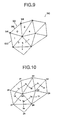
- the breadth-first traversal of the mesh triangles is defined as follows and is illustrated in Fig. 9, generally at 90.
- the edge 96 between the top-left node of the mesh and the next clockwise node 98 on the boundary is an edge of the triangle that is designated as the initial triangle. Label the initial triangle with the number 0.
- all other triangles are iteratively labeled with numbers 1, 2, ..., M - 1, where M is the number of triangles in the mesh.
- M is the number of triangles in the mesh.
- the initial triangle becomes the current triangle.
- the base edge of this triangle as the edge that connects this triangle to the already labeled neighboring triangle with the lowest number.
- the base edge is defined as the edge between the top-left node and the next clockwise node on the boundary.
- the triangle which has been labeled '3' is the 'current triangle'; the base edge is 'b'; the right and left edge are 'r' and 'l'.
- the triangles that will be labeled next are the triangles sharing the right, resp. left edge with the current triangle. After those triangles are labeled, the triangle which has been labeled '4' will be the next 'current triangle' and another motion vector will be encoded
- the ordering of the triangles according to their assigned label numbers implicitly defines the order in which the motion vector data of each node point is encoded.
- motion vector data for the top-left node of the mesh is encoded. No prediction is used for the motion vector of this node, hence this data specifies the motion vector itself.
- motion vector data for the second node which is the next clockwise node on the boundary with respect to the top-left node, is encoded. This data contains the prediction error for the motion vector of this node, where the motion vector of the top-left node is used as a prediction.
- the motion vectors of the two nodes that are on the base edge of the current triangle during that iteration are used to form a prediction for the motion vector of the third node of that triangle. If that third node is not yet labeled 'done', prediction error values are computed by subtracting the prediction from the actual motion vector, and the motion vector data is encoded by VLC. The third node is labeled 'done'. If the third note is already labeled 'done', it is simply ignored and no data is encoded.
- the breadth-first traversal of the triangles and the encoding of the node motion vector data may be performed simultaneously by making use of a first-in-first-out (FIFO) queue of triangles.
- FIFO first-in-first-out
- the motion vectors associated with these two nodes are encoded as described above.
- the (initially empty) FIFO queue is now initialized by appending the initial triangle at the end. Furthermore, the initial triangle is labeled with number 0, and its two already-processed nodes are marked 'done'. Next, the FIFO queue is processed as follows until it is empty.
- the ordered triple t k ⁇ p l , p m , p n ⁇ that is at the head of the queue is removed from the queue.
- the base edge, right edge and left edge of this triangle may be identified immediately from this triple.
- p n is marked 'done', no further action is taken; otherwise, a prediction vector is computed using the already encoded motion vectors associated with the first two nodes in the triple, p l and p m , and the actual motion vector at p n .
- the prediction error values are encoded by VLC.
- the subject node point now marked 'done'. Determine whether t k has an adjacent triangle sharing the right edge that has not yet been labeled.
- Every triangle in the mesh has at least one adjacent neighbor, and triangles are labeled when visited, every triangle is visited exactly once and the traversal terminates when (and only when) all triangles have been visited.
- the breadth-first traversal of triangles defines an ordering in which node points are visited. Node points may be visited more than once, but their motion vectors are encoded only at the first time a node is visited. Each node is labeled at the time of encoding, such that no attempt will be made to encode the corresponding motion vector again.
- the unique ordering of node points corresponds to the order of motion vector data put in the bit stream.
- the breadth-first traversal process is illustrated in Fig. 10 for a small triangular mesh, showing a traversal of triangles arbitrarily numbered t 0 , ..., t 9 and the corresponding ordering of node points arbitrarily numbered p 0 , ..., p 9 .
- the initial triangle t 3 is defined using the top-left node p 3 and the next clockwise node on the boundary p 1 .
- the motion vector v 3 is encoded without using any prediction; the motion vector v 1 is encoded using only v 3 as a prediction. Nodes p 3 and p 1 are marked 'done'.
- the triangle queue is initialized with t 3 and t 3 is labeled.
- the actual breadth-first traversal of the mesh now starts by removing the front element from the queue, in this case t 3 .
- the motion vector of its third node, v 6 is now encoded using v 3 and v 1 as predictors and putting the prediction error in the bit stream.
- Node p 6 is marked 'done'.
- the next step is to append any triangles adjacent to the current triangle t 3 and not yet labeled to the triangle queue.
- the triangle on the right of the current triangle (in this case t 5 ) is appended first; then the triangle on the left (in this case t 0 ); both are labeled.
- the next iteration of the traversal commences by removing the front element from the queue, in this case t 5 .
- the motion vector of its third node, v 7 is now encoded using v 3 and v 6 as predictors and retrieving the prediction error from the bit stream.
- Node p 7 is marked 'done' and the connected triangle t 8 is appended to the triangle queue and labeled.
- mesh_object_start_code has been decoded by mesh decoder 40
- a sequence of mesh object planes is decoded, until a mesh_object_end_code is detected.
- the new_mesh_flag of the mesh object plane class determines whether the data that follows specifies the initial geometry of a new dynamic mesh, in which case the data is sent to geometry decoder 42, or whether it specifies the motion of nodes from the previous mesh to the current mesh, in a sequence of meshes, in which case the data is sent to motion vector decoder 44.
- the mesh_type_code (Table 8) specifies whether the initial mesh is uniform or Delaunay.
- five parameters specify the geometry of a uniform mesh (Table 5).
- the first two decoded parameters specify the number of nodes in the horizontal and vertical, respectively, direction of the uniform mesh.
- the next two decoded parameters specify horizontal and vertical size of each rectangle (containing two triangles) in units accurate to half pixel units.
- the last parameter specifies how each rectangle is split into two triangles.
- N the total number of node points in the mesh N is decoded; then, the number of node points that are on the boundary of the mesh N b is decoded.
- N N i +N b .
- the x-, and y-coordinates of the first node point are decoded, which is specified in half-pixel units by a fixed length code (FLC). All the other node point locations are computed by adding differential values to previously decoded node locations. In particular, a delta_x, and delta_y value is added to the x- and y-coordinate, respectively, of the previously decoded node location.
- the delta_x and delta_y value are each decoded by first decoding a variable length code (VLC) specifying their respective lengths, delta_x_len_vlc and delta_y_len_vlc, and then decoding their values.
- VLC variable length code
- the differential values are decoded using variable length codes used at the encoder.
- the ordering in the sequence of decoded locations is such that the first N b locations correspond to boundary nodes (in counterclockwise direction).
- the decoder is able to reconstruct the boundary of the mesh by connecting each pair of successive boundary nodes, as well as the first and the last, by straight-line edge segments.
- the next N - N b values in the sequence of decoded locations correspond to interior node points.
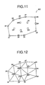
- the locations of both the boundary and interior nodes may be reconstructed, in addition to the polygonal shape of the boundary. This is illustrated in Fig. 11, which depicts decoded node points (rectangles) and mesh boundary edge segments (straight lines) that are the input to the constrained Delaunay triangulation.
- the mesh is finally obtained by applying constrained Delaunay triangulation to the set of decoded node points, where the edge segments on the mesh boundary are used as constraints.
- Delaunay triangulation proceeds by inserting an edge between two node points if there exists a circle through these two points that does not contain any other node point in its interior and does not intersect any other node point.
- the boundary edge segments present the only exceptions to this definition and may not be removed in the process.
- Each node point p n of a 2D mesh numbered k in the sequence of meshes has a 2D motion vector v n , defined from mesh k to k +1.
- v n 2D motion vector
- Method I is based on a predictive coding technique where only one motion vector is used as a predictor.
- a unique ordering of the node points p n is available, where n denotes the ordering number.
- this ordering is simply defined as the order in which the node point locations are received during mesh geometry decoding. The node point for which the location was received first is p 0 , the node point for which the location was received after that is p 1 , etc.
- the node ordering is defined on the basis of the mesh structure as previously described in the section entitled "Encoding of Node Motion Vectors: Method I.” This ordering, defined by a simple traversal of the uniform mesh, is illustrated in Fig. 8.
- a one bit flag specifies whether that node point has a non-zero motion vector.
- a motion vector difference vector e n specifies the difference between the motion vector of that node and the previously decoded motion vector.
- the first node point in the ordering has a non-zero motion vector
- Method II is based on a predictive coding technique where two motion vectors are used to compute a predictor.
- a breadth-first traversal is used to visit all the triangles and nodes in the mesh numbered k , and to decode the motion vectors defined from mesh k to k +1.
- the breadth-first traversal of the triangles is defined in the section on "Encoding of Node Motion Vectors: Method II,” and may be applied similarly to the decoding phase.
- the ordering of the triangles according to their label numbers assigned during the breadth-first traversal implicitly defines the order in which the motion vector data of each node point is decoded, as described in the following.
- motion vector data for the top-left node of the mesh is retrieved from the bit stream.
- No prediction is used for the motion vector of this node, hence this data specifies the motion vector itself.
- Motion vector data for the second node which is the next clockwise node on the boundary with respect to the top-left node, is retrieved from the bit stream. This data contains the prediction error for the motion vector of this node, where the motion vector of the top-left node is used as a prediction.
- These first two nodes (that form the base edge of the initial triangle) are marked with the label 'done'.
- the motion vectors of the two nodes that are on the base edge of the current triangle during that iteration are used to form a prediction for the motion vector of the third node of that triangle. If that third node is not yet labeled 'done', motion vector data is retrieved from the bit stream and used as prediction error values, i.e., the decoded values are added to the prediction to obtain the actual motion vector. That third node is then labeled 'done'. If the third note is already labeled 'done', then it is simply ignored and no data is retrieved from the bit stream.
- the two nodes on the base edge of a triangle are guaranteed to be labeled 'done' when that triangle becomes the 'current triangle', signifying that their motion vectors have already been decoded and may be used as predictors.
- Every triangle in the mesh has at least one adjacent neighbor, and triangles are labeled when visited, every triangle is visited exactly once and the traversal terminates when (and only when) all triangles have been visited.
- Node points may be visited more than once, but their motion vectors are decoded only at the first time a node is visited and each node is labeled at the time of decoding, therefore, no attempt will be made to decode the corresponding motion vector again.
- the unique ordering of node points corresponds to the order of motion vector data present in the bit stream.
- the breadth-first traversal of the triangles and the decoding of the node motion vector data may be performed simultaneously by making use of a first-in-first-out (FIFO) queue of triangles.
- FIFO first-in-first-out
- Fig. 10 depicts a traversal of triangles arbitrarily numbered t 0 , ..., t 9 and the corresponding ordering of node points arbitrarily numbered p 0 , ..., p 9 .
- the motion vector of its third node, v 7 is now decoded using v 3 and v 6 as predictors and retrieving the prediction error from the bit stream.
- Node p 7 is marked 'done' and the connected triangle t 8 is appended to the triangle queue and labeled. Such iterations continue until the triangle queue is empty and all node motion vectors have been decoded; the steps of the algorithm are also illustrated in Table 2.
- the following is an implementation of the invention within the current version of MPEG-4 Working Draft (WD )V 5.0.
- the Working Draft specifies only the decoding process.
- the following is an object-oriented pseudo computer code implementing the decoding process for both the mesh geometry and motion vectors according to the structure of the current specification of MPEG-4 WD V 5.0.
- the Mesh Object class defines the syntax for a sequence of 2D meshes.
- the Mesh Object Plane class defines the syntax for coding a single 2D mesh, either as a new mesh or with respect to the previously coded mesh.
- the Mesh Geometry class defines the syntax for coding the 2D geometry of a new mesh, which may either be a uniform mesh or a Delaunay triangulated mesh.
- the Mesh Motion class defines the syntax for coding the 2D motion vectors of the previous 2D mesh to the current mesh, thereby coding the current 2D mesh.
- the mesh bit stream syntax consists of two parts: mesh geometry and mesh motion.
- the mesh geometry is only encoded when a new mesh needs to be initialized; it consists of the initial positions of the mesh nodes.
- the mesh motion is encoded at subsequent time instants to describe the motion of the dynamic mesh; it consists of a motion vector for each mesh node.
- the dynamic mesh syntax allows for coding different types of 2D mesh structures, e.g., uniform or Delaunay-constrained and different magnitude ranges for the node motion vectors.
- the node coordinate and node motion vector accuracy is 0.5 pixel.
- marker_bit -- This one-bit code is set to "1". Setting this bit to "1" prevents emulation of start codes.
- new_mesh_flag mesh coding type 1 I coded by geometry
- 0 P coded by motion with respect to previous mesh
- triangle_split_code type 00 split all rectangles top-left to bottom-right 01 split all rectangles bottom-left to top-right 10 split alternately top-left to bottom-right and bottom-left to top-right 11 split alternately bottom-left to top-right and cop-left to bottom-right
- the delta_x_len_vlc and delta_x codes together specify the difference between the x-coordinates of a node (vertex) and the previously encoded node (vertex).
- the definition of the delta_x_len_vlc and delta_x codes are given in the MPEG-4 Video Verification Model 7.0 (VM 7.0) (N1642, section 4.7.1.1) (April 1997), hereinafter MPEG-4 VVM 7.0, where they are used for sprite trajectory coding.
- the definition of the delta_x_len_vlc and delta_x codes are given in the MPEG-4 VVM 7.0, section 4.7.1.1, where they are used for sprite trajectory coding.
- delta_y_len_vlc and delta_y codes together specify the difference between the y-coordinates of a node (vertex) and the previously encoded node (vertex).
- the definition of the delta_y_len_vlc and delta_y codes are given in the MPEG-4 VVM 7.0, section 4.7.1.1, where they are used for sprite trajectory coding.
- the definition of the delta_y_len_vlc and delta_y codes are given in the MPEG-4 VVM 7.0, section 4.7.1.1, where they are used for sprite trajectory coding.
- motion_range_code motion vector range in half sample units 1 [-32, 31] 2 [-64, 63] 3 [-128, 127]
- the section on the decoding process describes how the predicting motion vector is found.
- the definition of the delta_mv_x_vlc and delta_mv_x_res codes are given in the MPEG-4 VVM 7.0, section 6.1.8 and 6.1.9, Table 30, where they are used for motion vector difference coding.
- delta_mv_x_vlc This is a fixed length code defining the residual in the difference of motion vectors as encoded by delta_mv_x_vlc.
- the definition of the delta_mv_x_vlc and delta_mv_x_res codes are given in the MPEG-4 VVM 7.0, section 6.1.8 and 6.1.9, where they are used for motion vector difference coding.
- the section on the decoding process describes how the predicting motion vector is found.
- the definition of the delta_mv_y_vlc and delta_mv_y_res codes are given in the MPEG-4 VVM 7.0 section 6.1.8 and 6.1.9, Table 30, where they are used for motion vector difference coding.
- delta_mv_y_vlc This is a fixed length code defining the residual in the difference of motion vectors as encoded by delta_mv_y_vlc.
- delta_mv_y_vlc and delta_mv_y_res codes are given in the MPEG-4 VVM 7.0 section 6.1.8 and 6.1.9, where they are used for motion vector difference coding.
- the 2D dynamic mesh representation supports the following applications:
- the animation parameters of a 3D mesh model are often synthetically specified.
- the animation parameters of a 2D mesh model may likewise be specified synthetically, but they may also be derived from a natural video sequence by motion estimation.
- mesh modeling allows us to interactively combine natural and synthetic objects within a unified framework. Possible applications include object transfiguration (replacing one object by another object in moving video), augmented reality (augmenting/overlaying an object in moving video with graphics or text) and spatio/temporal image interpolation (zooming or frame-rate conversion)
- Motion estimation and compensation have proven to be important tools for video coding systems to obtain high compression ratios.
- the properties of the mesh-based motion model make it a suitable alternative to block-based motion modeling for use as a motion compensation tool in video coding in which case the motion vectors of mesh nodes are transmitted instead of block-motion vectors.
- Mesh-based video compression may for instance be performed by transmitting texture maps only at selected key frames and by animating these texture maps (without sending any prediction error image) for the intermediate frames using 2D mesh information. Only the image data of the first frame of a sequence is encoded, as well as the mesh motion data corresponding to all frames of the sequence. In case the initial mesh is adapted to image content, information about the initial mesh geometry has to be encoded and transmitted as well.
- the initial mesh geometry is sometimes restricted to limit the overhead involved (e.g., uniform meshes); however, more general mesh geometry compression schemes may be applied in case of multimedia coding, where several objects (video, audio, text, 2D / 3D meshes etc.) are encoded independently.
- Content-based random access to individual video objects becomes a desirable feature in several distributed multimedia applications, such as object-based browsing/editing/manipulation of video databases.
- Useful motion and shape features may be derived from the 2D content-based triangular mesh representation of video which may be employed in such applications.
Claims (8)
- Verfahren zum Codieren und Decodieren eines dynamischen Gitters, umfassend:Codieren und Decodieren einer Gittergeometrie aus einer Gruppe von Knotenpunkten; undCodieren und Decodieren eines Gitterknoten-Bewegungsvektors für jeden Knotenpunkt;wobei zum Codieren und Decodieren eines Gitterknoten-Bewegungsvektors Folgendes gehört:a) Komprimieren der Bewegungsvektoren für jeden Knotenpunkt unter Verwendung eines linearen Durchlaufs der Knotenpunkte und einer Vorhersage, unter Verwendung einer Vorhersage erster oder höherer Ordnung, folgender Bewegungsvektoren für jeden Knotenpunkt; oderb) Komprimieren der Bewegungsvektoren für jeden Knotenpunkt unter Verwendung eines Umfang-zuerst-Durchlaufs der Knotenpunkte und eines Vorhersagens, unter Verwendung einer Vorhersage zweiter oder höherer Ordnung, folgender Bewegungsvektoren für jeden Knotenpunkt;wobei es zum Komprimieren/Vorhersagen in den Schritten a) bzw. b) gehört, Vorhersagefehler unter Verwendung von Codes variabler Länge zu codieren und zu decodieren.
- Verfahren nach Anspruch 1, bei dem das dynamische Gitter Polygonflecke enthält.
- Verfahren nach Anspruch 2, bei dem die Polygonflecke Dreiecke sind und die Knotenpunkte die diesen Dreiecken entsprechenden Ecken sind.
- Verfahren nach Anspruch 1, 2 oder 3, bei dem es zum Codieren und Decodieren einer Gittergeometrie gehört, eine Gittertopologie vom Delaunay-Typ zu komprimieren.
- Verfahren nach Anspruch 1, 2 oder 3, bei dem es zum Codieren und Decodieren einer Gittergeometrie gehört, eine Gittertopologie von gleichmäßigem Typ zu komprimieren.
- Verfahren nach Anspruch 1, 2 oder 3, bei dem die Gitterknotenpunkte für ein Gitter vom Delaunay-Typ durchlaufen und geordnet werden.
- Verfahren nach Anspruch 1, 2 oder 3, bei dem die Gitterknotenpunkte für ein Gitter von gleichmäßigem Typ durchlaufen und geordnet werden.
- System zum Codieren und Decodieren einer Abfolge von durch ein dynamisches Gitter repräsentierten Bildern, wobei das dynamische Gitter über eine vordefinierte Geometrie verfügt, die einem beliebigen, zu repräsentierenden Objekt entspricht, mit einer Gruppe von Knotenpunkten an beliebigen Stellen und Bewegungsvektoren für die Knotenpunkte, mit:einem Codierer-Untersystem zum Codieren der Gittergeometrie der Gruppe von Knotenpunkten und zum Codieren eines Gitterknoten-Bewegungsvektors für jeden Knotenpunkt, mit:einem Texturcodierer zum Codieren der Textur eines Bilds und zum Erzeugen eines Bildbitstroms hieraus;einem Gittercodierer zum Codieren einer Gittersequenz, der einen Geometriecodierer zum Codieren der Geometrie eines Gitters und einen Bewegungsvektorcodierer zum Codieren der Bewegungsvektoren des Gitters und zum Erzeugen eines Gittercodebitstroms hieraus enthält;einem Decodierer-Untersystem zum Decodieren der Gittergeometrie der Gruppe von Knotenpunkten und zum Decodieren eines Gitterknoten-Bewegungsvektors für jeden Knotenpunkt, mit:einem Texturdecodierer zum Decodieren der Textur eines Bilds aus einem Bildbitstrom;einem Gitterdecodierer zum Decodieren des Gittercodebitstroms, der einen Geometriedecodierer zum Decodieren der Geometrie des Gitters und einem Bewegungsvektordecodierer zum Decodieren der Bewegungsvektoren des Gitters enthält; undeiner Animationsanwendung zum Kombinieren der codierten Texturdaten und des decodierten Gitters und zum Erzeugen eines animierten Bilds hieraus.
Applications Claiming Priority (5)
| Application Number | Priority Date | Filing Date | Title |
|---|---|---|---|
| US3301196P | 1996-12-16 | 1996-12-16 | |
| US33011P | 1996-12-16 | ||
| US08/942,313 US6047088A (en) | 1996-12-16 | 1997-10-01 | 2D mesh geometry and motion vector compression |
| US942313 | 1997-10-01 | ||
| PCT/JP1997/004607 WO1998027515A1 (en) | 1996-12-16 | 1997-12-15 | 2-d mesh geometry and motion vector compression |
Publications (2)
| Publication Number | Publication Date |
|---|---|
| EP1008108A1 EP1008108A1 (de) | 2000-06-14 |
| EP1008108B1 true EP1008108B1 (de) | 2003-05-14 |
Family
ID=26709176
Family Applications (1)
| Application Number | Title | Priority Date | Filing Date |
|---|---|---|---|
| EP97947938A Expired - Lifetime EP1008108B1 (de) | 1996-12-16 | 1997-12-15 | 2-d gittergeometrie und bewegungsvektorkompression |
Country Status (5)
| Country | Link |
|---|---|
| US (1) | US6047088A (de) |
| EP (1) | EP1008108B1 (de) |
| JP (1) | JP2001506828A (de) |
| DE (1) | DE69722040T2 (de) |
| WO (1) | WO1998027515A1 (de) |
Cited By (1)
| Publication number | Priority date | Publication date | Assignee | Title |
|---|---|---|---|---|
| TWI419075B (zh) * | 2010-05-14 | 2013-12-11 | Univ Nat Cheng Kung | 一種不等比例影片縮放之圖像處理器 |
Families Citing this family (69)
| Publication number | Priority date | Publication date | Assignee | Title |
|---|---|---|---|---|
| US6525722B1 (en) * | 1995-08-04 | 2003-02-25 | Sun Microsystems, Inc. | Geometry compression for regular and irregular mesh structures |
| KR100215451B1 (ko) * | 1996-05-29 | 1999-08-16 | 윤종용 | 임의형태 물체를 포함한 동화상의 부호화 및 복호화시스템 |
| DE69835039T2 (de) | 1997-02-14 | 2007-07-12 | The Trustees Of Columbia University In The City Of New York | Objektbasiertes audiovisuelles Endgerät und entsprechende Bitstromstruktur |
| US7920143B1 (en) * | 1997-03-27 | 2011-04-05 | At&T Intellectual Property Ii, L.P. | Method for defining animation parameters for an animation definition interface |
| KR100249223B1 (ko) * | 1997-09-12 | 2000-03-15 | 구자홍 | 엠팩(mpeg)-4의움직임벡터코딩방법 |
| US7199836B1 (en) * | 1998-02-13 | 2007-04-03 | The Trustees Of Columbia University In The City Of New York | Object-based audio-visual terminal and bitstream structure |
| US6271861B1 (en) * | 1998-04-07 | 2001-08-07 | Adobe Systems Incorporated | Smooth shading of an object |
| US6236738B1 (en) * | 1998-04-09 | 2001-05-22 | Board Of Trustees Of The Leland Stanford Junior University | Spatiotemporal finite element method for motion analysis with velocity data |
| US6167159A (en) * | 1998-04-30 | 2000-12-26 | Virtue Ltd. | Triangle mesh compression |
| US6342884B1 (en) | 1999-02-03 | 2002-01-29 | Isurftv | Method and apparatus for using a general three-dimensional (3D) graphics pipeline for cost effective digital image and video editing, transformation, and representation |
| FR2794329B1 (fr) * | 1999-05-26 | 2001-08-17 | France Telecom | Procede de codage d'images hierarchique, a mise en oeuvre selective d'un codage a base transformation reversible, et procede de decodage correspondant |
| FR2794269B1 (fr) * | 1999-05-26 | 2001-08-17 | France Telecom | Procede de codage d'images, a partition triangulaire et transformation reversible, et procede de decodage correspondant |
| US6356457B1 (en) | 1999-06-07 | 2002-03-12 | Sun Microsystems, Inc. | Circuit card support mechanism and method |
| US6792108B1 (en) * | 1999-06-08 | 2004-09-14 | Universite de Montrëal | Aperiodic encryption for digital data |
| US6628277B1 (en) * | 1999-06-14 | 2003-09-30 | Sun Microsystems, Inc. | Decompression of three-dimensional graphics data using mesh buffer references to reduce redundancy of processing |
| US8595764B2 (en) | 1999-06-25 | 2013-11-26 | Jlb Ventures, Llc | Image-oriented electronic programming guide |
| FR2802377B1 (fr) * | 1999-12-09 | 2002-03-08 | France Telecom | Procede d'estimation de mouvement entre deux images avec gestion des retournements de mailles et procede de codage correspondant |
| US6757330B1 (en) | 2000-06-01 | 2004-06-29 | Hewlett-Packard Development Company, L.P. | Efficient implementation of half-pixel motion prediction |
| US6847684B1 (en) | 2000-06-01 | 2005-01-25 | Hewlett-Packard Development Company, L.P. | Zero-block encoding |
| US6650335B2 (en) * | 2001-02-22 | 2003-11-18 | Mitsubishi Electric Research Laboratories, Inc. | Method for extracting static and dynamic super-resolution textures form a sequence of images |
| US7623739B2 (en) * | 2001-07-11 | 2009-11-24 | Ecole Polytechnique Federale De Lausanne (Epfl) | Method and computing system for creating and displaying images with animated microstructures |
| GB2379299B (en) * | 2001-09-04 | 2006-02-08 | Imagination Tech Ltd | A texturing system |
| US20030193503A1 (en) * | 2002-04-10 | 2003-10-16 | Mark Seminatore | Computer animation system and method |
| US6947045B1 (en) | 2002-07-19 | 2005-09-20 | At&T Corporation | Coding of animated 3-D wireframe models for internet streaming applications: methods, systems and program products |
| US8421804B2 (en) * | 2005-02-16 | 2013-04-16 | At&T Intellectual Property Ii, L.P. | System and method of streaming 3-D wireframe animations |
| FR2852773A1 (fr) * | 2003-03-20 | 2004-09-24 | France Telecom | Procedes et dispositifs de codage et de decodage d'une sequence d'images par decomposition mouvement/texture et codage par ondelettes |
| US7324105B1 (en) * | 2003-04-10 | 2008-01-29 | Nvidia Corporation | Neighbor and edge indexing |
| US7313285B2 (en) * | 2003-05-30 | 2007-12-25 | Lucent Technologies Inc. | Method and apparatus for compressing and decompressing images captured from viewpoints throughout N-dimensional space |
| US7983835B2 (en) * | 2004-11-03 | 2011-07-19 | Lagassey Paul J | Modular intelligent transportation system |
| US7529418B2 (en) * | 2004-05-20 | 2009-05-05 | Hewlett-Packard Development Company, L.P. | Geometry and view assisted transmission of graphics image streams |
| US9743078B2 (en) | 2004-07-30 | 2017-08-22 | Euclid Discoveries, Llc | Standards-compliant model-based video encoding and decoding |
| US9578345B2 (en) | 2005-03-31 | 2017-02-21 | Euclid Discoveries, Llc | Model-based video encoding and decoding |
| US9532069B2 (en) | 2004-07-30 | 2016-12-27 | Euclid Discoveries, Llc | Video compression repository and model reuse |
| US8902971B2 (en) | 2004-07-30 | 2014-12-02 | Euclid Discoveries, Llc | Video compression repository and model reuse |
| US8942283B2 (en) | 2005-03-31 | 2015-01-27 | Euclid Discoveries, Llc | Feature-based hybrid video codec comparing compression efficiency of encodings |
| AU2006230545B2 (en) * | 2005-03-31 | 2010-10-28 | Euclid Discoveries, Llc | Apparatus and method for processing video data |
| CN1852444B (zh) * | 2005-12-28 | 2010-05-12 | 华为技术有限公司 | 基于小波的自适应视频编码方法 |
| US7589746B2 (en) * | 2006-03-23 | 2009-09-15 | Intel Corporation | Optimized frustum clipping via cached clip vertices |
| EP2015256A4 (de) * | 2006-04-24 | 2010-05-12 | Panasonic Corp | Zeichnungsvorrichtung und zeichnungsverfahren |
| WO2008091484A2 (en) | 2007-01-23 | 2008-07-31 | Euclid Discoveries, Llc | Object archival systems and methods |
| JP2010517427A (ja) | 2007-01-23 | 2010-05-20 | ユークリッド・ディスカバリーズ・エルエルシー | 個人向けのビデオサービスを提供するシステムおよび方法 |
| CA2676219C (en) | 2007-01-23 | 2017-10-24 | Euclid Discoveries, Llc | Computer method and apparatus for processing image data |
| US8249371B2 (en) * | 2007-02-23 | 2012-08-21 | International Business Machines Corporation | Selective predictor and selective predictive encoding for two-dimensional geometry compression |
| EP2387004B1 (de) | 2010-05-11 | 2016-12-14 | Dassault Systèmes | Verlustfreie Kompression einer strukturierten Menge von Fließkommazahlen, insbesondere für CAD-Systeme |
| US9588489B2 (en) * | 2010-06-24 | 2017-03-07 | Disney Enterprises, Inc. | Computational highlight holography |
| JP5661359B2 (ja) * | 2010-07-16 | 2015-01-28 | キヤノン株式会社 | 画像処理装置、画像処理方法、およびプログラム |
| US9582934B2 (en) * | 2010-09-20 | 2017-02-28 | Siemens Healthcare Gmbh | Method and system for efficient extraction of a silhouette of a 3D mesh |
| US9392301B2 (en) | 2011-07-01 | 2016-07-12 | Qualcomm Incorporated | Context adaptive entropy coding for non-square blocks in video coding |
| US9161012B2 (en) * | 2011-11-17 | 2015-10-13 | Microsoft Technology Licensing, Llc | Video compression using virtual skeleton |
| US9892535B1 (en) | 2012-01-05 | 2018-02-13 | Google Inc. | Dynamic mesh generation to minimize fillrate utilization |
| EP2904584B1 (de) * | 2012-10-05 | 2017-08-09 | Universidade De Coimbra | Verfahren zur ausrichtung und verfolgung von punktbereichen in bildern mit radialer verzerrung und ausgabe von bewegungsmodellparametern, verzerrungskalibrierung und zoomvariation |
| US10699361B2 (en) * | 2012-11-21 | 2020-06-30 | Ati Technologies Ulc | Method and apparatus for enhanced processing of three dimensional (3D) graphics data |
| US9633459B2 (en) * | 2013-08-23 | 2017-04-25 | Disney Enterprises, Inc. | Methods and systems for creating a hull that may have concavities |
| US9773331B2 (en) | 2013-08-23 | 2017-09-26 | Disney Enterprises, Inc. | Methods and systems for efficient graphics rendering |
| US10097851B2 (en) | 2014-03-10 | 2018-10-09 | Euclid Discoveries, Llc | Perceptual optimization for model-based video encoding |
| US9621917B2 (en) | 2014-03-10 | 2017-04-11 | Euclid Discoveries, Llc | Continuous block tracking for temporal prediction in video encoding |
| US10091507B2 (en) | 2014-03-10 | 2018-10-02 | Euclid Discoveries, Llc | Perceptual optimization for model-based video encoding |
| USRE49930E1 (en) | 2015-03-26 | 2024-04-23 | Universidade De Coimbra | Methods and systems for computer-aided surgery using intra-operative video acquired by a free moving camera |
| WO2016168307A1 (en) | 2015-04-13 | 2016-10-20 | Universidade De Coimbra | Methods and systems for camera characterization in terms of response function, color, and vignetting under non-uniform illumination |
| CN107292963B (zh) * | 2016-04-12 | 2020-01-17 | 杭州海康威视数字技术股份有限公司 | 一种三维模型的调整方法及装置 |
| WO2017191978A1 (en) * | 2016-05-02 | 2017-11-09 | Samsung Electronics Co., Ltd. | Method, apparatus, and recording medium for processing image |
| KR101763921B1 (ko) | 2016-10-21 | 2017-08-01 | (주)플럭스플래닛 | 컨텐츠 스트리밍 시스템 및 방법 |
| US10796499B2 (en) | 2017-03-14 | 2020-10-06 | Universidade De Coimbra | Systems and methods for 3D registration of curves and surfaces using local differential information |
| GB2563895B (en) * | 2017-06-29 | 2019-09-18 | Sony Interactive Entertainment Inc | Video generation method and apparatus |
| US10708597B2 (en) | 2018-02-01 | 2020-07-07 | Microsoft Technology Licensing, Llc | Techniques for extrapolating image frames |
| US11631218B2 (en) * | 2018-12-11 | 2023-04-18 | Google Llc | Efficient compression of data representing triangular mesh attributes |
| US20200202622A1 (en) * | 2018-12-19 | 2020-06-25 | Nvidia Corporation | Mesh reconstruction using data-driven priors |
| US20210287431A1 (en) * | 2020-03-15 | 2021-09-16 | Intel Corporation | Apparatus and method for displaced mesh compression |
| US20220051466A1 (en) * | 2020-08-17 | 2022-02-17 | Intel Corporation | Apparatus and method for compressing ray tracing acceleration structure build data |
Family Cites Families (8)
| Publication number | Priority date | Publication date | Assignee | Title |
|---|---|---|---|---|
| SE465394B (sv) * | 1990-08-15 | 1991-09-02 | Televerket | Metod foer roerelsekompensering och elastisk deformation i bildsekvenser |
| JPH06325151A (ja) * | 1993-03-17 | 1994-11-25 | Fujitsu Ltd | アニメーション編集装置 |
| JP2838968B2 (ja) * | 1994-01-31 | 1998-12-16 | 日本電気株式会社 | 半導体デバイスシミュレータのメッシュ生成方法 |
| DE69619002T2 (de) * | 1995-03-10 | 2002-11-21 | Toshiba Kawasaki Kk | Bildkodierungs-/-dekodierungsvorrichtung |
| US5654771A (en) * | 1995-05-23 | 1997-08-05 | The University Of Rochester | Video compression system using a dense motion vector field and a triangular patch mesh overlay model |
| US5778192A (en) * | 1995-10-26 | 1998-07-07 | Motorola, Inc. | Method and device for optimal bit allocation between different sources of information in digital video compression |
| US5825369A (en) * | 1996-01-16 | 1998-10-20 | International Business Machines Corporation | Compression of simple geometric models using spanning trees |
| US5748789A (en) * | 1996-10-31 | 1998-05-05 | Microsoft Corporation | Transparent block skipping in object-based video coding systems |
-
1997
- 1997-10-01 US US08/942,313 patent/US6047088A/en not_active Expired - Lifetime
- 1997-12-15 DE DE69722040T patent/DE69722040T2/de not_active Expired - Lifetime
- 1997-12-15 WO PCT/JP1997/004607 patent/WO1998027515A1/en active Search and Examination
- 1997-12-15 EP EP97947938A patent/EP1008108B1/de not_active Expired - Lifetime
- 1997-12-15 JP JP52753598A patent/JP2001506828A/ja not_active Ceased
Cited By (1)
| Publication number | Priority date | Publication date | Assignee | Title |
|---|---|---|---|---|
| TWI419075B (zh) * | 2010-05-14 | 2013-12-11 | Univ Nat Cheng Kung | 一種不等比例影片縮放之圖像處理器 |
Also Published As
| Publication number | Publication date |
|---|---|
| DE69722040T2 (de) | 2004-04-01 |
| DE69722040D1 (de) | 2003-06-18 |
| US6047088A (en) | 2000-04-04 |
| WO1998027515A1 (en) | 1998-06-25 |
| EP1008108A1 (de) | 2000-06-14 |
| JP2001506828A (ja) | 2001-05-22 |
Similar Documents
| Publication | Publication Date | Title |
|---|---|---|
| EP1008108B1 (de) | 2-d gittergeometrie und bewegungsvektorkompression | |
| van Beek et al. | Hierarchical 2-D mesh representation, tracking, and compression for object-based video | |
| EP3043320B1 (de) | System und verfahren zur komprimierung von 3d-rechnergrafiken | |
| Lee et al. | A layered video object coding system using sprite and affine motion model | |
| US5936671A (en) | Object-based video processing using forward-tracking 2-D mesh layers | |
| Briceño Pulido | Geometry videos: a new representation for 3D animations | |
| US7616782B2 (en) | Mesh based frame processing and applications | |
| Tekalp et al. | Two-dimensional mesh-based visual-object representation for interactive synthetic/natural digital video | |
| JP4151158B2 (ja) | シーン記述生成装置及び方法 | |
| US20080031325A1 (en) | Mesh-based video compression with domain transformation | |
| KR20220137937A (ko) | 투영 기반 메시 압축 | |
| JP2002506585A (ja) | マスクおよび丸め平均値を使用したオブジェクトベースの符号化システムのためのスプライト生成に関する方法 | |
| US20050017968A1 (en) | Differential stream of point samples for real-time 3D video | |
| Malassiotis et al. | Model-based joint motion and structure estimation from stereo images | |
| JP2023544618A (ja) | ビデオベースのメッシュ圧縮 | |
| JP2001186516A (ja) | 画像データの符号化復号化方法及び装置 | |
| Chou et al. | Dynamic polygon clouds: Representation and compression for VR/AR | |
| Malassiotis et al. | Object-based coding of stereo image sequences using three-dimensional models | |
| Kim et al. | Generalized predictive binary shape coding using polygon approximation | |
| Malassiotis et al. | Coding of video-conference stereo image sequences using 3D models | |
| Chai et al. | A depth map representation for real-time transmission and view-based rendering of a dynamic 3D scene | |
| CA2466247A1 (en) | Mesh based frame processing and applications | |
| Mamou et al. | Multi-chart geometry video: A compact representation for 3D animations | |
| KR20060015755A (ko) | 3차원 모델을 사용하는 화상 시퀀스를 표현하는 방법 및 그장치와 신호 | |
| Mamou et al. | A preliminary evaluation of 3D mesh animation coding techniques |
Legal Events
| Date | Code | Title | Description |
|---|---|---|---|
| PUAI | Public reference made under article 153(3) epc to a published international application that has entered the european phase |
Free format text: ORIGINAL CODE: 0009012 |
|
| 17P | Request for examination filed |
Effective date: 19990528 |
|
| AK | Designated contracting states |
Kind code of ref document: A1 Designated state(s): DE FR GB |
|
| 17Q | First examination report despatched |
Effective date: 20011016 |
|
| GRAH | Despatch of communication of intention to grant a patent |
Free format text: ORIGINAL CODE: EPIDOS IGRA |
|
| GRAH | Despatch of communication of intention to grant a patent |
Free format text: ORIGINAL CODE: EPIDOS IGRA |
|
| GRAA | (expected) grant |
Free format text: ORIGINAL CODE: 0009210 |
|
| AK | Designated contracting states |
Designated state(s): DE FR GB |
|
| REG | Reference to a national code |
Ref country code: GB Ref legal event code: FG4D |
|
| RIN1 | Information on inventor provided before grant (corrected) |
Inventor name: TEKALP, AHMET, MURAT Inventor name: VAN BEEK, PETRUS, J., L. |
|
| REF | Corresponds to: |
Ref document number: 69722040 Country of ref document: DE Date of ref document: 20030618 Kind code of ref document: P |
|
| ET | Fr: translation filed | ||
| PLBE | No opposition filed within time limit |
Free format text: ORIGINAL CODE: 0009261 |
|
| STAA | Information on the status of an ep patent application or granted ep patent |
Free format text: STATUS: NO OPPOSITION FILED WITHIN TIME LIMIT |
|
| 26N | No opposition filed |
Effective date: 20040217 |
|
| REG | Reference to a national code |
Ref country code: DE Ref legal event code: R082 Ref document number: 69722040 Country of ref document: DE Representative=s name: MUELLER - HOFFMANN & PARTNER PATENTANWAELTE, DE |
|
| REG | Reference to a national code |
Ref country code: FR Ref legal event code: TP Owner name: RAKUTEN, INC., JP Effective date: 20131016 |
|
| REG | Reference to a national code |
Ref country code: GB Ref legal event code: 732E Free format text: REGISTERED BETWEEN 20131024 AND 20131030 |
|
| REG | Reference to a national code |
Ref country code: DE Ref legal event code: R082 Ref document number: 69722040 Country of ref document: DE Representative=s name: MUELLER HOFFMANN & PARTNER PATENTANWAELTE MBB, DE Effective date: 20131014 Ref country code: DE Ref legal event code: R082 Ref document number: 69722040 Country of ref document: DE Representative=s name: MUELLER - HOFFMANN & PARTNER PATENTANWAELTE, DE Effective date: 20131014 Ref country code: DE Ref legal event code: R081 Ref document number: 69722040 Country of ref document: DE Owner name: RAKUTEN, INC, JP Free format text: FORMER OWNER: SHARP K.K., OSAKA, JP Effective date: 20131014 |
|
| REG | Reference to a national code |
Ref country code: FR Ref legal event code: PLFP Year of fee payment: 19 |
|
| REG | Reference to a national code |
Ref country code: FR Ref legal event code: CA Effective date: 20151223 |
|
| REG | Reference to a national code |
Ref country code: FR Ref legal event code: PLFP Year of fee payment: 20 |
|
| PGFP | Annual fee paid to national office [announced via postgrant information from national office to epo] |
Ref country code: GB Payment date: 20161222 Year of fee payment: 20 Ref country code: DE Payment date: 20161213 Year of fee payment: 20 |
|
| PGFP | Annual fee paid to national office [announced via postgrant information from national office to epo] |
Ref country code: FR Payment date: 20161222 Year of fee payment: 20 |
|
| REG | Reference to a national code |
Ref country code: DE Ref legal event code: R071 Ref document number: 69722040 Country of ref document: DE |
|
| REG | Reference to a national code |
Ref country code: GB Ref legal event code: PE20 Expiry date: 20171214 |
|
| PG25 | Lapsed in a contracting state [announced via postgrant information from national office to epo] |
Ref country code: GB Free format text: LAPSE BECAUSE OF EXPIRATION OF PROTECTION Effective date: 20171214 |