EP1006630A2 - Combustion chamber for vehicle - Google Patents
Combustion chamber for vehicle Download PDFInfo
- Publication number
- EP1006630A2 EP1006630A2 EP99123630A EP99123630A EP1006630A2 EP 1006630 A2 EP1006630 A2 EP 1006630A2 EP 99123630 A EP99123630 A EP 99123630A EP 99123630 A EP99123630 A EP 99123630A EP 1006630 A2 EP1006630 A2 EP 1006630A2
- Authority
- EP
- European Patent Office
- Prior art keywords
- combustion chamber
- insulator body
- spark plug
- electrodes
- spark
- Prior art date
- Legal status (The legal status is an assumption and is not a legal conclusion. Google has not performed a legal analysis and makes no representation as to the accuracy of the status listed.)
- Granted
Links
Images

Classifications
-
- H—ELECTRICITY
- H01—ELECTRIC ELEMENTS
- H01T—SPARK GAPS; OVERVOLTAGE ARRESTERS USING SPARK GAPS; SPARKING PLUGS; CORONA DEVICES; GENERATING IONS TO BE INTRODUCED INTO NON-ENCLOSED GASES
- H01T13/00—Sparking plugs
- H01T13/02—Details
- H01T13/08—Mounting, fixing or sealing of sparking plugs, e.g. in combustion chamber
-
- F—MECHANICAL ENGINEERING; LIGHTING; HEATING; WEAPONS; BLASTING
- F02—COMBUSTION ENGINES; HOT-GAS OR COMBUSTION-PRODUCT ENGINE PLANTS
- F02B—INTERNAL-COMBUSTION PISTON ENGINES; COMBUSTION ENGINES IN GENERAL
- F02B75/00—Other engines
- F02B75/12—Other methods of operation
- F02B2075/125—Direct injection in the combustion chamber for spark ignition engines, i.e. not in pre-combustion chamber
-
- F—MECHANICAL ENGINEERING; LIGHTING; HEATING; WEAPONS; BLASTING
- F02—COMBUSTION ENGINES; HOT-GAS OR COMBUSTION-PRODUCT ENGINE PLANTS
- F02B—INTERNAL-COMBUSTION PISTON ENGINES; COMBUSTION ENGINES IN GENERAL
- F02B23/00—Other engines characterised by special shape or construction of combustion chambers to improve operation
- F02B23/08—Other engines characterised by special shape or construction of combustion chambers to improve operation with positive ignition
- F02B23/10—Other engines characterised by special shape or construction of combustion chambers to improve operation with positive ignition with separate admission of air and fuel into cylinder
- F02B23/101—Other engines characterised by special shape or construction of combustion chambers to improve operation with positive ignition with separate admission of air and fuel into cylinder the injector being placed on or close to the cylinder centre axis, e.g. with mixture formation using spray guided concepts
-
- Y—GENERAL TAGGING OF NEW TECHNOLOGICAL DEVELOPMENTS; GENERAL TAGGING OF CROSS-SECTIONAL TECHNOLOGIES SPANNING OVER SEVERAL SECTIONS OF THE IPC; TECHNICAL SUBJECTS COVERED BY FORMER USPC CROSS-REFERENCE ART COLLECTIONS [XRACs] AND DIGESTS
- Y02—TECHNOLOGIES OR APPLICATIONS FOR MITIGATION OR ADAPTATION AGAINST CLIMATE CHANGE
- Y02T—CLIMATE CHANGE MITIGATION TECHNOLOGIES RELATED TO TRANSPORTATION
- Y02T10/00—Road transport of goods or passengers
- Y02T10/10—Internal combustion engine [ICE] based vehicles
- Y02T10/12—Improving ICE efficiencies
Definitions
- the invention relates to a combustion chamber Internal combustion engine that has a fuel injector and one into a jet area of the injector protruding spark plug with two by one Insulator body includes separate electrodes.
- Such a combustion chamber is known from DE 196 27 524.
- a spark plug is used, the electrodes face each other on an air gap.
- the present invention solves the problem by instead of an air gap a series of against the electrodes and conductive insulated from each other Provides elements that a path for one Spark between the two electrodes on one side of the insulator body facing away from the injection valve establish.
- This feature Improvement in ignition behavior is attributed to that a long, particularly effective Spark arises, and that at the same time that of Injection valve facing away, i.e. in the slipstream lying side of the insulator body the speed the flow of the ignition mixture low and its turbulence is low so the spark is not is deflected.
- the smallest drops of the ignition mixture their movement closest to those in the combustion chamber Air flow follows, the one facing away from the injector Reach side of the insulator body. This Drops can be vaporized with the least amount of energy and therefore for the ignition of the mixture particularly valuable.
- the insulator body preferably has the shape of a tube, one of the electrodes passing through the tube extends and has a head which according to a preferred embodiment an end face of the pipe covered.
- the total width of this column can be Air gap width of a conventional spark plug correspond. But as soon as a spark on the If split columns are ignited, the individual unite Partial sparks quickly become one over the extending the entire distance between the electrodes Spark.
- This Shielding shield only causes small-scale additional Turbulence as that in its slipstream lying volume essentially from the insulator body is filled out.
- the shield can be on the wall of the combustion chamber or also be mounted on the spark plug, whereby the latter solution has the advantage of being application the invention also in a conventional Internal combustion engine only by exchanging the Allows spark plugs.
- FIG. 1 schematically shows an injection valve 10 and a spark plug 11 as related to each other are arranged in a combustion chamber, the wall 14 is only schematically indicated in sections.
- the Injector 10 injects the fuel onto its combustion chamber end 12 into the combustion chamber.
- the fuel spreads in about one Cone as indicated by dashed lines 13 is out in the combustion chamber and is doing so atomized so that a fuel-air mixture is formed.
- the thread 15 and the complementary internal thread the bore of the combustion chamber wall 14, which the Spark plug picks are sized so that the spark plug 11 then reaches a screwed position, when the ground electrode 16 and the conductive Elements 20 attach to the from the injector 10 facing away from the spark plug.
- an intermediate ring (not shown) be used between one Flange of the spark plug and a step of the bore the combustion chamber wall 14 or the outside thereof lie, and its thickness chosen in each case is that the spark plug is screwed tight Position reached when the conductive Elements 20 on the side facing away from the injection valve Side of the insulator body.
- This spark is extremely stable since it because of its close proximity to the surface of the insulator body 17 no significant turbulence Is exposed to currents that flow into it could tear away in one direction or another. It this creates a very stable spark that with the fuel-air mixture flowing out of the isolator body is well supplied and very reliable and ignites evenly.
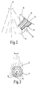
- FIG. 2 shows a modification of the arrangement from FIG 1.
- FIG. 3 shows a top view of this end in FIG axial direction.
- a shield 21 is in one piece with the thread 15 of the spark plug and the ground electrode 16 are formed and extends the entire length of the insulator body 17 up to the level of the head 19 the center electrode.
- This head is with this Designed as a hook-shaped element, that is from the longitudinal axis of the spark plug from the shield 21 in the radial direction to the edge of the cylindrical outer surface of the insulator body 17 extends.
- This design the head 19 excludes that an ignition spark between the head and the shield 21 skips. The spark is rather like that first embodiment, reliably along the conductive Elements 20 led to the ground electrode 16.
- the shield 21 also has the effect that most of the ejected from the injector Prevents fuel droplets directly to hit the insulator body 17 and to cool it too much, which leads to the formation of Cause cracks in its ceramic material and the lifespan could reduce the spark plug. So can the insulator body 17 in the operation of the internal combustion engine a constant high working temperature reach and prevents soot on the insulator body 17 sets off its insulation effect could affect.
- the Insulator body 17 against the body of the spark plug be freely rotatable and have a coding that in a complementary coding of the location hole the combustion chamber wall 14 engages so that during screwing the spark plug in the isolator from Start with the desired orientation in relation to the Injector is in and during screwing maintains.
- the shield can also rotatable and with the isolator body be firmly connected.
Abstract
Description
Die Erfindung betrifft eine Brennkammer einer Brennkraftmaschine, die ein Kraftstoff-Einspritzventil und eine in einen Strahlbereich des Einspritzventils ragende Zündkerze mit zwei durch einen Isolatorkörper getrennten Elektroden umfaßt.The invention relates to a combustion chamber Internal combustion engine that has a fuel injector and one into a jet area of the injector protruding spark plug with two by one Insulator body includes separate electrodes.
Eine solche Brennkammer ist aus DE 196 27 524 bekannt. Bei dieser bekannten Brennkammerkonstruktion wird eine Zündkerze eingesetzt, deren Elektroden sich beiderseits eines Luftspalts gegenüberliegen.Such a combustion chamber is known from DE 196 27 524. In this known combustion chamber construction a spark plug is used, the electrodes face each other on an air gap.
Bei einer Zündkerze mit Luftspalt tritt das Problem auf, daß bei starken Strömungen im Bereich des Luftspalts ein zwischen den Elektroden erzeugter Zündfunke von der Strömung mitgerissen wird, den Kontakt zu den Elektroden verliert und verlöscht, noch bevor er in der Lage ist, das Gemisch auf Zündtemperatur zu erhitzen. Zwar entsteht, solange Zündspannung anliegt, umgehend ein neuer Funke, doch ist die Gefahr nicht zu vernachlässigen, daß diesem das gleiche Schicksal widerfährt. Um diesen Effekt zu reduzieren, wurde in DE 196 27 524 vorgeschlagen, den Luftspalt mit Hilfe einer zu diesem konzentrisch angeordneten, im Querschnitt kreissektorförmigen Abschirmung gegen den direkten Einfluß des Einspritzstrahls zu schützen. Eine vollauf befriedigende Lösung des Problems des Ausblasens des Funkens wurde bislang jedoch nicht gefunden.The problem occurs with a spark plug with an air gap on that with strong currents in the area of Air gap created between the electrodes Ignition spark is carried away by the current Contact with the electrodes is lost and extinguished, even before he is able to open the mixture Heat the ignition temperature. Although arises as long Ignition voltage is present, immediately a new spark, but the danger cannot be neglected that the same fate happens to them. To this To reduce the effect, it was proposed in DE 196 27 524 the air gap using one to this concentrically arranged, sector-shaped in cross section Shield against direct influence to protect the injection jet. A completely satisfactory one Solving the blowout problem However, sparking has not yet been found.
Die vorliegende Erfindung löst das Problem, indem sie anstelle eines Luftspalts eine Reihe von gegen die Elektroden und gegeneinander isolierten leitfähigen Elementen vorsieht, die eine Bahn für einen Zündfunken zwischen den zwei Elektroden an einer vom Einspritzventil abgewandten Seite des Isolatorkörpers festlegen. Die durch dieses Merkmal erzielte Verbesserung des Zündverhaltens wird darauf zurückgeführt, daß ein langer, besonders wirksamer Funke entsteht, und daß gleichzeitig an der vom Einspritzventil abgewandten, also im Windschatten liegenden Seite des Isolatorkörpers die Geschwindigkeit der Strömung des Zündgemischs niedrig und seine Turbulenz gering ist, so daß der Funke nicht ausgelenkt wird. Hinzu kommt, daß insbesondere die kleinsten Tropfen des Zündgemischs, deren Bewegung am engsten der in der Brennkammer herrschenden Luftströmung folgt, die vom Einspritzventil abgewandte Seite des Isolatorkörpers erreichen. Diese Tropfen sind mit dem geringsten Energieaufwand verdampfbar und deshalb für die Zündung des Gemischs besonders wertvoll.The present invention solves the problem by instead of an air gap a series of against the electrodes and conductive insulated from each other Provides elements that a path for one Spark between the two electrodes on one side of the insulator body facing away from the injection valve establish. The achieved by this feature Improvement in ignition behavior is attributed to that a long, particularly effective Spark arises, and that at the same time that of Injection valve facing away, i.e. in the slipstream lying side of the insulator body the speed the flow of the ignition mixture low and its turbulence is low so the spark is not is deflected. In addition, the smallest drops of the ignition mixture, their movement closest to those in the combustion chamber Air flow follows, the one facing away from the injector Reach side of the insulator body. This Drops can be vaporized with the least amount of energy and therefore for the ignition of the mixture particularly valuable.
Zur Begrenzung von Turbulenzen im Windschatten des Isolatorkörpers ist es sinnvoll, diesen zylindrisch zu formen. To limit turbulence in the slipstream of the Insulator body, it makes sense to cylindrical this to shape.
Dabei hat der Isolatorkörper vorzugsweise die Form eines Rohres, wobei sich eine der Elektroden durch das Rohr erstreckt und einen Kopf aufweist, der gemäß einer bevorzugten Ausgestaltung eine Stirnfläche des Rohrs überdeckt.The insulator body preferably has the shape of a tube, one of the electrodes passing through the tube extends and has a head which according to a preferred embodiment an end face of the pipe covered.
Eine Länge der Bahn des Zündfunkens von 4 mm hat sich als geeignet erwiesen. Diese Länge kann mit einer Zündspannung erreicht werden, die sich nicht wesentlich von der herkömmlicher Zündkerzen mit Luftspalt unterscheidet, da die zwischen den Elektroden angeordneten leitfähigen Elemente zunächst die Entstehung sehr starker elektrischer Felder in den Teilspalten zwischen einer Elektrode und einem Element beziehungsweise zwischen den Elementen begünstigen. Die Gesamtbreite dieser Spalte kann der Breite des Luftspalts einer herkömmlichen Zündkerze entsprechen. Sobald aber ein Funke auf den Teilspalten gezündet ist, vereinigen sich die einzelnen Teilfunken schnell zu einem sich über die gesamte Strecke zwischen den Elektroden erstreckenden Funken.Has a length of the spark path of 4 mm proved to be suitable. This length can with an ignition voltage that cannot be reached much different from the conventional spark plugs Air gap differs because of that between the electrodes arranged conductive elements initially the creation of very strong electric fields in the partial columns between an electrode and a Favor element or between the elements. The total width of this column can be Air gap width of a conventional spark plug correspond. But as soon as a spark on the If split columns are ignited, the individual unite Partial sparks quickly become one over the extending the entire distance between the electrodes Spark.
Um den eventuell gegen Temperatursprünge empfindlichen Isolatorkörper vor einer zu heftigen Abkühlung durch auftreffendes Gemisch an der dem Einspritzventil zugewandten Seite zu schützen, kann an dieser Seite ein Abschirmschild montiert sein. Dieser Abschirmschild verursacht nur kleinräumige zusätzliche Turbulenzen, da das in seinem Windschatten liegende Volumen im wesentlichen von dem Isolatorkörper ausgefüllt ist. In order to be sensitive to temperature changes Insulator body before cooling too violently by impinging mixture on the injector Protect facing side can at this A shielding shield must be installed. This Shielding shield only causes small-scale additional Turbulence as that in its slipstream lying volume essentially from the insulator body is filled out.
Der Abschirmschild kann an der Wand der Brennkammer oder auch an der Zündkerze montiert sein, wobei letztere Lösung den Vorteil hat, daß sie die Anwendung der Erfindung auch in einer herkömmlichen Brennkraftmaschine alleine durch Austausch der Zündkerzen ermöglicht.The shield can be on the wall of the combustion chamber or also be mounted on the spark plug, whereby the latter solution has the advantage of being application the invention also in a conventional Internal combustion engine only by exchanging the Allows spark plugs.
Um zu garantieren, daß die in der Wand einer Brennkammer montierte Zündkerze die richtige Orientierung hat, sind ein Außengewinde der Zündkerze und ein Innengewinde einer Aufnahmebohrung der Brennkammerwand so angelegt, daß sie eine festverschraubte Stellung der Zündkerze festlegen, in der die leitfähigen Elemente sich an der vom Einspritzventil abgewandten Seite des Isolatorkörpers befinden. Eine entsprechende Wirkung kann erzielt werden, wenn bei der Verschraubung der Zündkerze in der Aufnahmebohrung ein Ausgleichsring von passend zu wählender Dicke verwendet wird.To guarantee that in the wall of a combustion chamber mounted spark plug the correct orientation has an external thread of the spark plug and an internal thread of a receiving bore of the combustion chamber wall so that it is screwed tight Determine the position of the spark plug in the the conductive elements attach to the from the injector facing away from the insulator body. A corresponding effect can be achieved if when screwing the spark plug in a matching ring from the mounting hole thickness to be selected.
Weitere Merkmale und Vorteile der Erfindung ergeben sich aus der nachfolgenden Beschreibung von Ausführungsbeispielen.Further features and advantages of the invention result itself from the following description of exemplary embodiments.
Es zeigen:
- Figur 1
- ein Einspritzventil und eine Zündkerze, eingebaut in die Wand einer Brennkammer;
- Figur 2
- eine Variante der Zündkerze gemäß der Erfindung; und
- Figur 3
- eine Draufsicht auf die Zündkerze aus Figur 2.
- Figure 1
- an injector and a spark plug built into the wall of a combustion chamber;
- Figure 2
- a variant of the spark plug according to the invention; and
- Figure 3
- a plan view of the spark plug of Figure 2.
Figur 1 zeigt schematisch ein Einspritzventil 10
und eine Zündkerze 11, wie sie in Bezug zueinander
in einer Brennkammer angeordnet sind, deren Wand 14
nur ausschnittweise schematisch angedeutet ist. Das
Einspritzventil 10 spritzt den Brennstoff an seinem
brennkammerseitigen Ende 12 in die Brennkammer ein.
Dabei breitet sich der Brennstoff in etwa in einem
Kegel, wie er durch die gestrichelten Linien 13 angegeben
ist, in der Brennkammer aus, und wird dabei
vernebelt, so daß ein Kraftstoff-Luft-Gemisch entsteht.FIG. 1 schematically shows an
In Nachbarschaft zum Einspritzventil 10 ist die
Zündkerze 11 mit ihrem Außengewinde 15 in der Wand
14 der Brennkammer verschraubt. Am brennkammerseitigen
Ende des Gewindes 15 steht eine mit dem Gewinde
einteilige Spitze 16 ins Innere der Brennkammer
und in Richtung der Achse der Zündkerze 11 vor.
Diese Spitze bildet eine Masseelektrode des Zündfunkens.
Entlang der Achse der Zündkerze erstreckt
sich ein hohlzylindrischer Isolatorkörper 17. Eine
Mittelelektrode 18 verläuft stiftförmig durch den
axialen Hohlraum des Isolatorkörpers 17 bis zu einem
Kopf 19, der die der Brennkammer zugewandte
Stirnfläche des Isolatorkörpers 17 abdeckt. Der
Isolatorkörper 17 trägt an seiner der Masseelektrode
16 zugewandten und von dem Einspritzventil 10
abgewandten Seite eine Reihe von leitfähigen Elementen
20. In the neighborhood of the
Das Gewinde 15 sowie das dazu komplementäre Innengewinde
der Bohrung der Brennkammerwand 14, die die
Zündkerze aufnimmt, sind so bemessen, daß die Zündkerze
11 eine festverschraubte Stellung dann erreicht,
wenn die Masseelektrode 16 und die leitfähigen
Elemente 20 sich an der von dem Einspritzventil
10 abgewandten Seite der Zündkerze befindet.The
Alternativ hierzu kann bei der Montage der Zündkerze
11 im Bedarfsfall ein Zwischenring (nicht dargestellt)
eingesetzt werden, der zwischen einem
Flansch der Zündkerze und einer Stufe der Bohrung
der Brennkammerwand 14 oder deren Außenseite zu
liegen kommt, und dessen Dicke jeweils so gewählt
wird, daß die Zündkerze eine fest verschraubte
Stellung dann erreicht, wenn sich die leitfähigen
Elemente 20 an der vom Einspritzventil abgewandten
Seite des Isolatorkörpers befinden.Alternatively, when installing the
Wenn Kraftstoff in die Brennkammer eingespritzt
wird, verdampft er größtenteils spontan, mischt
sich mit Luft und wird zusammen mit eventuell verbleibenden
kleinen Kraftstofftröpfchen in der Strömung
an die abgewandte Seite des Isolatorkörpers 17
in die Nähe der leitfähigen Elemente 20 geführt.
Wenn an die Mittelelektrode 18 eine Zündspannung
angelegt wird, bilden sich starke elektrische Felder
an der Oberfläche des Isolatorkörpers 17 im Bereich
zwischen dem Kopf 19 der Mittelelektrode und
dem nächstliegenden leitfähigen Element 20, zwischen
den leitfähigen Elementen 20 sowie zwischen
dem letzten der leitfähigen Elemente 20 und der
Masseelektrode 16. Diese zünden zunächst den Funken
auf den einzelnen Spalten zwischen den Elektroden
16, 18 und den leitfähigen Elementen 20, die sich
binnen Mikrosekunden zu einem einheitlichen, sich
über die leitfähigen Elemente 20 hinweg von einer
Elektrode 18 zur anderen 16 erstreckenden Funken
vereinigen. Dieser Funke ist äußerst stabil, da er
aufgrund seiner engen Nachbarschaft zur Oberfläche
des Isolatorkörpers 17 keinen wesentlichen turbulenten
Strömungen ausgesetzt ist, die ihn in die
eine oder andere Richtung fortreißen könnten. Es
entsteht somit ein sehr stabiler Zündfunken, der
mit dem den Isolatorkörper unströmenden Kraftstoffluftgemisch
gut versorgt ist und sehr zuverlässig
und gleichmäßig zündet.When fuel is injected into the combustion chamber
it evaporates spontaneously, mostly spontaneously, mixes
yourself with air and will along with any remaining
small droplets of fuel in the flow
to the opposite side of the
Figur 2 zeigt eine Abwandlung der Anordnung aus Figur
1. In Figur 2 sind lediglich die Spitze 12 des
Einspritzventils, der davon ausgehende Kraftstoffnebel
sowie das brennkammerseitige Ende der Zündkerze
11 im Schnitt dargestellt.
Figur 3 zeigt eine Draufsicht auf dieses Ende in
axialer Richtung.FIG. 2 shows a modification of the arrangement from FIG
1. In Figure 2, only the
Ein Abschirmschild 21 ist einteilig mit dem Gewinde
15 der Zündkerze und der Masseelektrode 16 ausgebildet
und erstreckt sich über die gesamte Länge
des Isolatorkörpers 17 bis in Höhe des Kopfes 19
der Mittelelektrode. Dieser Kopf ist bei dieser
Ausgestaltung als ein hakenförmiges Element ausgebildet,
das sich von der Längsachse der Zündkerze
aus in radialer Richtung von dem Abschirmschild 21
fort bis an den Rand der zylindrischen Außenfläche
des Isolatorkörpers 17 erstreckt. Diese Gestaltung
des Kopfes 19 schließt aus, daß ein Zündfunke zwischen
dem Kopf und dem Abschirmschild 21 überspringt.
Der Zündfunke wird vielmehr, wie bei der
ersten Ausgestaltung, zuverlässig entlang der leitfähigen
Elemente 20 zur Masseelektrode 16 geführt.A
Wie durch Striche 22 in den Figuren 2 und 3 angedeutet,
umströmt das Luft-Kraftstoff-Gemisch vom
Ende 12 des Einspritzventils aus die Zündkerze, wobei
sich an der von dem Einspritzventil abgewandten
Seite des Isolatorkörpers 17 (siehe Figur 2) sowie
an den seitlichen Kanten des Abschirmschildes 21
(siehe Figur 3) mäßig turbulente Bereiche ausbilden,
die durch Spirallinien angedeutet sind. Dabei
ist allerdings der Zündfunken durch den Isolatorkörper
17 weitgehend vor dem direkten Einfluß der
Turbulenzen geschützt. Turbulenzen, die am Abschirmschild
21 entstehen, sind, durch den Abstand
zwischen der Kante des Abschirmschildes 21 und der
Oberfläche des Isolatorkörpers 17 bestimmt, kleinräumig
im Verhältnis zu den Abmessungen der Zündkerze
und sind deshalb weitgehend abgeklungen und
haben somit zu einer effektiven Homogenisierung des
Luft-Kraftstoff-Gemischs beigetragen, bevor dieses
Gemisch die Rückseite des Isolatorkörpers 17 und
den Zündfunken zwischen den zwei Elektroden erreicht.
Auf diese Weise ist für eine gute und
gleichmäßige Gemischstoffversorgung des Zündfunkens
gesorgt.As indicated by lines 22 in FIGS. 2 and 3,
flows around the air-
Der Abschirmschild 21 hat zusätzlich die Wirkung,
daß er einen Großteil der vom Einspritzventil ausgestoßenen
Kraftstofftröpfchen daran hindert, direkt
auf den Isolatorkörper 17 aufzutreffen und
diesen zu stark abzukühlen, was zur Bildung von
Rissen in dessen Keramikmaterial führen und die Lebensdauer
der Zündkerze verringern könnte. So kann
der Isolatorkörper 17 im Betrieb der Brennkraftmaschine
eine gleichbleibend hohe Arbeitstemperatur
erreichen und verhindert, daß sich Ruß auf dem Isolatorkörper
17 absetzt, der dessen Isolationswirkung
beeinträchtigen könnte.The
Gemäß einer nicht dargestellten Abwandlung kann der
Isolatorkörper 17 gegen den Körper der Zündkerze
frei drehbar sein und eine Kodierung aufweisen, die
in eine komplementäre Kodierung der Aufnahmebohrung
der Brennkammerwand 14 eingreift, so daß während
des Einachraubens der Zündkerze der Isolator von
Anfang an die gewünschte Orientierung in Bezug zum
Einspritzventil innehat und während des Verschraubens
beibehält. Bei dieser Variante kann der Abschirmschild
ebenfalls drehbar und mit dem Isolatorkörper
fest verbunden sein.According to a modification, not shown, the
Claims (8)
Applications Claiming Priority (2)
| Application Number | Priority Date | Filing Date | Title |
|---|---|---|---|
| DE19855791 | 1998-12-03 | ||
| DE19855791A DE19855791A1 (en) | 1998-12-03 | 1998-12-03 | Combustion chamber for a motor vehicle |
Publications (3)
| Publication Number | Publication Date |
|---|---|
| EP1006630A2 true EP1006630A2 (en) | 2000-06-07 |
| EP1006630A3 EP1006630A3 (en) | 2001-01-31 |
| EP1006630B1 EP1006630B1 (en) | 2003-02-19 |
Family
ID=7889849
Family Applications (1)
| Application Number | Title | Priority Date | Filing Date |
|---|---|---|---|
| EP99123630A Expired - Lifetime EP1006630B1 (en) | 1998-12-03 | 1999-11-27 | Combustion chamber for vehicle |
Country Status (3)
| Country | Link |
|---|---|
| EP (1) | EP1006630B1 (en) |
| JP (1) | JP2000170635A (en) |
| DE (2) | DE19855791A1 (en) |
Cited By (1)
| Publication number | Priority date | Publication date | Assignee | Title |
|---|---|---|---|---|
| DE102006042457B4 (en) * | 2006-09-09 | 2010-06-10 | Ford Global Technologies, LLC, Dearborn | Aligned spark plug |
Families Citing this family (2)
| Publication number | Priority date | Publication date | Assignee | Title |
|---|---|---|---|---|
| DE102007024878A1 (en) | 2007-05-29 | 2008-12-04 | GM Global Technology Operations, Inc., Detroit | Spark plug and cylinder head for it |
| DE102021214629A1 (en) | 2021-12-17 | 2023-06-22 | Robert Bosch Gesellschaft mit beschränkter Haftung | Spark plug with element for directing the flow on the front side of the housing on the combustion chamber side |
Citations (6)
| Publication number | Priority date | Publication date | Assignee | Title |
|---|---|---|---|---|
| US2129576A (en) * | 1936-09-16 | 1938-09-06 | Frank A Gorny | Spark plug |
| US4272697A (en) * | 1979-03-01 | 1981-06-09 | Bernard Wax | Spark plug with annular rings in insulating core channels forming series gap |
| US5187404A (en) * | 1991-08-05 | 1993-02-16 | Cooper Industries, Inc. | Surface gap igniter |
| EP0748012A1 (en) * | 1995-06-08 | 1996-12-11 | Ngk Spark Plug Co., Ltd | A spark plug for an internal combustion engine and a method of making the same |
| DE19627524A1 (en) * | 1996-07-09 | 1998-01-15 | Bosch Gmbh Robert | Sparking plug for use on fuel-injected IC engines |
| US5731654A (en) * | 1993-09-15 | 1998-03-24 | Robert Bosch Gmbh | Spark plug having a creepage spark gap |
-
1998
- 1998-12-03 DE DE19855791A patent/DE19855791A1/en not_active Withdrawn
-
1999
- 1999-11-27 EP EP99123630A patent/EP1006630B1/en not_active Expired - Lifetime
- 1999-11-27 DE DE59904322T patent/DE59904322D1/en not_active Expired - Fee Related
- 1999-12-03 JP JP11345366A patent/JP2000170635A/en active Pending
Patent Citations (6)
| Publication number | Priority date | Publication date | Assignee | Title |
|---|---|---|---|---|
| US2129576A (en) * | 1936-09-16 | 1938-09-06 | Frank A Gorny | Spark plug |
| US4272697A (en) * | 1979-03-01 | 1981-06-09 | Bernard Wax | Spark plug with annular rings in insulating core channels forming series gap |
| US5187404A (en) * | 1991-08-05 | 1993-02-16 | Cooper Industries, Inc. | Surface gap igniter |
| US5731654A (en) * | 1993-09-15 | 1998-03-24 | Robert Bosch Gmbh | Spark plug having a creepage spark gap |
| EP0748012A1 (en) * | 1995-06-08 | 1996-12-11 | Ngk Spark Plug Co., Ltd | A spark plug for an internal combustion engine and a method of making the same |
| DE19627524A1 (en) * | 1996-07-09 | 1998-01-15 | Bosch Gmbh Robert | Sparking plug for use on fuel-injected IC engines |
Cited By (1)
| Publication number | Priority date | Publication date | Assignee | Title |
|---|---|---|---|---|
| DE102006042457B4 (en) * | 2006-09-09 | 2010-06-10 | Ford Global Technologies, LLC, Dearborn | Aligned spark plug |
Also Published As
| Publication number | Publication date |
|---|---|
| EP1006630B1 (en) | 2003-02-19 |
| EP1006630A3 (en) | 2001-01-31 |
| DE19855791A1 (en) | 2000-06-21 |
| JP2000170635A (en) | 2000-06-20 |
| DE59904322D1 (en) | 2003-03-27 |
Similar Documents
| Publication | Publication Date | Title |
|---|---|---|
| EP0675272B1 (en) | Prechamber ignition device | |
| EP1492953B1 (en) | Combined fuel injection valve/ignition plug | |
| DE102011053530B4 (en) | Pre-chamber spark plug Method for producing a prechamber spark plug and method for promoting combustion in an internal combustion engine | |
| DE3731211C2 (en) | ||
| EP1265329B1 (en) | Spark plug of an internal combustion engine | |
| DE112015000466B4 (en) | IGNITER AND METHOD FOR GENERATION OF PLASMA DISCHARGE RADIATION | |
| DE10159910A1 (en) | The fuel injector-spark plug combination | |
| DE102006000070A1 (en) | Spark plug with a shield for a ground electrode | |
| DE2831442A1 (en) | INTERNAL COMBUSTION ENGINE WITH A MAIN COMBUSTION CHAMBER AND ITS COMPLETED IGNITION CHAMBER WITH IGNITION DEVICE | |
| WO2007092972A1 (en) | Sparkplug | |
| DE102012022872A1 (en) | Ignition device for combustion engine i.e. gas engine, has cylindrical central bore fluidly connected between ignition chamber and combustion chamber, where diameter of central bore is greater than diameter of another cylindrical bore | |
| CH621852A5 (en) | ||
| DE102007050634A1 (en) | spark plug | |
| DE10340043B4 (en) | spark plug | |
| DE112021003181T5 (en) | Spark plug for an internal combustion engine | |
| EP1006630B1 (en) | Combustion chamber for vehicle | |
| WO1997036354A1 (en) | Sparking plug connector for an internal combustion engine | |
| DE60100653T2 (en) | Sliding discharge spark plug with radial spark | |
| DE102015102745B4 (en) | Spark plug for a prechamber internal combustion engine | |
| DE3017948C2 (en) | ||
| DE69932684T2 (en) | Ceramic tip for glow sensor | |
| DE19843712A1 (en) | Spark plug assembly for internal combustion engine | |
| DE102007055873A1 (en) | Plasma ignition device, has spin producing unit arranged at surface of inner wall of insulator device, where spin producing unit is discharged with reversed gas from discharge chamber | |
| DE19627524A1 (en) | Sparking plug for use on fuel-injected IC engines | |
| EP0858139B1 (en) | Sparking plug |
Legal Events
| Date | Code | Title | Description |
|---|---|---|---|
| PUAI | Public reference made under article 153(3) epc to a published international application that has entered the european phase |
Free format text: ORIGINAL CODE: 0009012 |
|
| AK | Designated contracting states |
Kind code of ref document: A2 Designated state(s): DE FR GB IT |
|
| AX | Request for extension of the european patent |
Free format text: AL;LT;LV;MK;RO;SI |
|
| PUAL | Search report despatched |
Free format text: ORIGINAL CODE: 0009013 |
|
| AK | Designated contracting states |
Kind code of ref document: A3 Designated state(s): AT BE CH CY DE DK ES FI FR GB GR IE IT LI LU MC NL PT SE |
|
| AX | Request for extension of the european patent |
Free format text: AL;LT;LV;MK;RO;SI |
|
| RIC1 | Information provided on ipc code assigned before grant |
Free format text: 7H 01T 13/08 A, 7H 01T 13/52 B |
|
| 17P | Request for examination filed |
Effective date: 20010731 |
|
| AKX | Designation fees paid |
Free format text: DE FR GB IT |
|
| GRAG | Despatch of communication of intention to grant |
Free format text: ORIGINAL CODE: EPIDOS AGRA |
|
| 17Q | First examination report despatched |
Effective date: 20011207 |
|
| GRAG | Despatch of communication of intention to grant |
Free format text: ORIGINAL CODE: EPIDOS AGRA |
|
| GRAH | Despatch of communication of intention to grant a patent |
Free format text: ORIGINAL CODE: EPIDOS IGRA |
|
| GRAH | Despatch of communication of intention to grant a patent |
Free format text: ORIGINAL CODE: EPIDOS IGRA |
|
| GRAA | (expected) grant |
Free format text: ORIGINAL CODE: 0009210 |
|
| AK | Designated contracting states |
Designated state(s): DE FR GB IT |
|
| REG | Reference to a national code |
Ref country code: GB Ref legal event code: FG4D Free format text: NOT ENGLISH |
|
| REF | Corresponds to: |
Ref document number: 59904322 Country of ref document: DE Date of ref document: 20030327 Kind code of ref document: P |
|
| GBT | Gb: translation of ep patent filed (gb section 77(6)(a)/1977) | ||
| ET | Fr: translation filed | ||
| PGFP | Annual fee paid to national office [announced via postgrant information from national office to epo] |
Ref country code: GB Payment date: 20031103 Year of fee payment: 5 |
|
| PGFP | Annual fee paid to national office [announced via postgrant information from national office to epo] |
Ref country code: FR Payment date: 20031119 Year of fee payment: 5 |
|
| PGFP | Annual fee paid to national office [announced via postgrant information from national office to epo] |
Ref country code: DE Payment date: 20031215 Year of fee payment: 5 |
|
| PLBE | No opposition filed within time limit |
Free format text: ORIGINAL CODE: 0009261 |
|
| STAA | Information on the status of an ep patent application or granted ep patent |
Free format text: STATUS: NO OPPOSITION FILED WITHIN TIME LIMIT |
|
| 26N | No opposition filed |
Effective date: 20031120 |
|
| PG25 | Lapsed in a contracting state [announced via postgrant information from national office to epo] |
Ref country code: GB Free format text: LAPSE BECAUSE OF NON-PAYMENT OF DUE FEES Effective date: 20041127 |
|
| PG25 | Lapsed in a contracting state [announced via postgrant information from national office to epo] |
Ref country code: DE Free format text: LAPSE BECAUSE OF NON-PAYMENT OF DUE FEES Effective date: 20050601 |
|
| GBPC | Gb: european patent ceased through non-payment of renewal fee |
Effective date: 20041127 |
|
| PG25 | Lapsed in a contracting state [announced via postgrant information from national office to epo] |
Ref country code: FR Free format text: LAPSE BECAUSE OF NON-PAYMENT OF DUE FEES Effective date: 20050729 |
|
| REG | Reference to a national code |
Ref country code: FR Ref legal event code: ST |
|
| PG25 | Lapsed in a contracting state [announced via postgrant information from national office to epo] |
Ref country code: IT Free format text: LAPSE BECAUSE OF NON-PAYMENT OF DUE FEES Effective date: 20051127 |