EP1006005A2 - Ordnersystem und Vorrichtung zum Lochen von Blättern - Google Patents
Ordnersystem und Vorrichtung zum Lochen von Blättern Download PDFInfo
- Publication number
- EP1006005A2 EP1006005A2 EP99203559A EP99203559A EP1006005A2 EP 1006005 A2 EP1006005 A2 EP 1006005A2 EP 99203559 A EP99203559 A EP 99203559A EP 99203559 A EP99203559 A EP 99203559A EP 1006005 A2 EP1006005 A2 EP 1006005A2
- Authority
- EP
- European Patent Office
- Prior art keywords
- sheet
- supplied
- openings
- opening
- pins
- Prior art date
- Legal status (The legal status is an assumption and is not a legal conclusion. Google has not performed a legal analysis and makes no representation as to the accuracy of the status listed.)
- Withdrawn
Links
Images


Classifications
-
- B—PERFORMING OPERATIONS; TRANSPORTING
- B42—BOOKBINDING; ALBUMS; FILES; SPECIAL PRINTED MATTER
- B42F—SHEETS TEMPORARILY ATTACHED TOGETHER; FILING APPLIANCES; FILE CARDS; INDEXING
- B42F11/00—Filing appliances with separate intermediate holding means
Definitions
- the present invention concerns a sheet part that is supplied with devices to apply them in a filing system such as an album and/or folder on one side and supplied with fastening devices for the application of a sheet on the other side.
- Such a sheet part is known in European Patent no. 0 322 507.
- a filing folder is shown consisting of a number of bayonet-like gaps in the sheets that should couple to a support supplied with pins.
- a number of sheets are attached to each other and a joint strip is used that is supplied with the above described bayonet gaps.
- this is supplied with a pin shaped projection that snaps in a hole in the filing folder. Through which locking is generated. By removing this lock, it will be possible to take out such a collection of sheets out of the binding system.
- An object of this invention is to provide a sheet part by which it is possible to connect sheets or other parts in a simple way.
- sheet part contains coupling devices being two edge parts opposite to each other connected to that sheet part strip, with in between an inserting device for a sheet.
- Such sheets can contain any, in the technical art known structure.
- at least one part of the material that is added is self adhesive to which an additional sheet can be applied.
- two of such self adhesive parts are present, which are constructed approximately in V-shape in order to insert an additional sheet between this V-shape.
- the invention also relates to a filing system for separate sheets, consisting of a folder for inserting the sheets containing at least two inserting pins or rings of which at least one can be opened and closed, and which pins or rings are constructed to insert the sheets through the applied openings, whereby at least one of the openings is bounded along the complete circumference of the sheet.
- a protecting folder is generaly known in the technical art. By this the pins or rings are always removed for inserting a sheet.
- a more simple system for inserting sheets is the system used for suspension filing cabinets, by which they are supplied with an edge with gaps that have a bayonet-like outlet. Through gravity the concerned sheets are always filed with the outlet facing downwards so that getting loose of the sheets does not have to be feared.
- Such a system is unsuitable for ordners or other filing systems that are used in horizontal position.
- this further object is realized through the above described filing system because this one contains at least one other gap in the sheet that extends to end freely at the end edge of that sheet, by which the first part of this extension of that opening stretches out at least in the direction parallel to the connecting line between the pins or rings, by which the width of the extended limited groove is larger than the dimension of the cross-section of the pins or rings.
- the remaining part of the extension can be constructed in any suggested technical way. According a very simple construction this part stretches out perpendicularly from the first part, meaning the shortest way to the end edge of the concerned sheet.
- each sheet contains one opening for co-operation with the pins, meaning one all-sided limited opening, while two other openings are constructed as the above described bayonet-like shape. Besides it is important that these two bayonet-like shaped openings are constructed so that movement in the same direction cause the release of the sheet.
- the invention also relates to a sheet supplied with the above described openings.
- sheet also is meant a sheet part consisting of a material strip to which with help of coupling devices and such, an additional sheet can be applied.
- the invention also relates to a construction to apply the openings/gaps in a sheet consisting of a basic surface on which a construction is applied, by which between a part of that construction and the basic surface an inserting groove for a sheet or sheet part is bounded, by which the construction is supplied with coming and going movable punch devices perpendicular on the basic surface and by which that basic surface is supplied with devices that co-operate with the punch devices, by which the punch devices are equipped to make a gap/opening in that sheet.
- An example of such a construction is the well known perforator. According the invention this perforator is constructed in such a way that the above mentioned bayonet-like openings can be made.
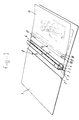
- FIG 1 and 2 a protective folder in total view is indicated with 1. This consists of two not further indicated and known contour parts connected by a back part. Hinges between the back and the contour respectively back side are made by means of hinges 2.
- a support 4 is attached, for example by glue.
- This support 4 is supplied with a hinge 5 through which the upper part of support 4, that is connected to supporting back 3, ables to hinge. By comparing figure 1 with 2 such a hinge movement will appear.
- Supporting back 3 is mainly U-shape constructed and supplied with two pins 6 as well as a screw-thread 7.
- Screw-thread 7 is constructed to receive a screw pin 8 which is also illustrated schematically in figure 1 and is shown in the applied position in figure 2.
- FIG 1 a sheet is applied. A next sheet is inserted. This next sheet is indicated with 15 and is supplied with a circular opening 16 which is bounded all-sided by the sheet. This is constructed to co-operate with screw pin 8. Besides, two bayonet-like openings 17 are present consisting of circular round holes supplied with extensions.
- the first part of the extension is indicated with 18 and stretches out in the direction of the connection line between pins 6 or the centre lines of the openings 16, 17. It is important that the expanding direction of both first parts of the extension 18 of both openings 17 is the same.
- a second part of the extension is indicated with 19 and stretches out from the first part of the extension to the free edge of the sheet 15.
- the above mentioned structure operates as follows: if a sheet 15 must be inserted in a folder that can already be filled with sheets, screw pin 8 is removed and the sheet 15 is positioned in such a way that the pins 6 in the second part of the extension indicated by 19 are moved. Next, the sheet 15 in figure 1 can be moved further to the left. Consequently, the sheet 15 in figure 1 is moved downwards so that the pins 6 become situated in the "upper" part of the opening 17. Exactly in this position, opening 16 is situated precisely beneath the insert opening of screw pin 8. Meaning, screw pin 8 can only be inserted in this position. After inserting screw pin 8 the sheet 15 is not only supported by opening 16, but also by openings 17. Moving the sheet 15 upwards is efficiently avoided by inserting pin 8.
- first pin 8 should be taken out and further by means of sliding the concerned sheet by placing the pins 6 in front of the second part of the extension of opening 17, indicated by 19, the sheet can be removed. By this the other sheets should not be moved and are kept in place by the pins 6.
- FIG. 3 illustrates a variation of the sheet shown in figures 1 and 2.
- the same openings 16 and 17 are applied.
- two with regard to each other movable edge parts 26 are applied. At least one of them is supplied with a self adhesive layer 27 which is protected by a protective foil 28.
- a protective foil 28 By removing the protective foil 28 while the edge parts 26 are separated, and followed by inserting a to be attached sheet 29, and pressing them against each other with the applied sheet in between, this sheet 29 can be attached to the strip 25.
- all sorts of sheets or other parts can be attached in a folder in a very simple manner. It will be understood, that the invention is also applicable to other structures by which sheets are attached to strips supplied with punch holes.
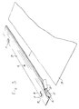
- Figure 4 illustrates an example of a structure for producing the above described openings. This is illustrated only very schematically and shows large resemblance with the known paper perforators.
- This structure is in total indicated with 31 and consists of a basic sheet 32 on which by means of a hinge 34 a control lever 33 is applied. Through the control lever 33 the punch pins 35 and 36 are operated which seize in the punch holes 37 respectively 38.
- the drawing clearly shows that the punch pins 36 are constructed for making circular holes in the concerned end part of the sheet while punch pins 36 are constructed for making the above described bayonet-like openings.
Landscapes
- Perforating, Stamping-Out Or Severing By Means Other Than Cutting (AREA)
- Sheet Holders (AREA)
Applications Claiming Priority (2)
| Application Number | Priority Date | Filing Date | Title |
|---|---|---|---|
| NL1010577 | 1998-11-17 | ||
| NL1010577A NL1010577C2 (nl) | 1998-11-17 | 1998-11-17 | Bladdeel, opbergsysteem alsmede inrichting voor het vervaardigen van openingen in een bladmateriaal. |
Publications (2)
| Publication Number | Publication Date |
|---|---|
| EP1006005A2 true EP1006005A2 (de) | 2000-06-07 |
| EP1006005A3 EP1006005A3 (de) | 2000-09-27 |
Family
ID=19768160
Family Applications (1)
| Application Number | Title | Priority Date | Filing Date |
|---|---|---|---|
| EP99203559A Withdrawn EP1006005A3 (de) | 1998-11-17 | 1999-10-29 | Ordnersystem und Vorrichtung zum Lochen von Blättern |
Country Status (2)
| Country | Link |
|---|---|
| EP (1) | EP1006005A3 (de) |
| NL (1) | NL1010577C2 (de) |
Cited By (1)
| Publication number | Priority date | Publication date | Assignee | Title |
|---|---|---|---|---|
| FR2913367A1 (fr) * | 2007-03-09 | 2008-09-12 | Visu Ad Sarl | Systeme de reliure, articles equipes d'un tel systeme et machine pour la perforation |
Citations (1)
| Publication number | Priority date | Publication date | Assignee | Title |
|---|---|---|---|---|
| FR2521911A1 (fr) * | 1982-02-23 | 1983-08-26 | Martin Tim J M | Accessoire pour l'adaptation de documents divers a des classeurs |
-
1998
- 1998-11-17 NL NL1010577A patent/NL1010577C2/nl not_active IP Right Cessation
-
1999
- 1999-10-29 EP EP99203559A patent/EP1006005A3/de not_active Withdrawn
Patent Citations (1)
| Publication number | Priority date | Publication date | Assignee | Title |
|---|---|---|---|---|
| FR2521911A1 (fr) * | 1982-02-23 | 1983-08-26 | Martin Tim J M | Accessoire pour l'adaptation de documents divers a des classeurs |
Cited By (1)
| Publication number | Priority date | Publication date | Assignee | Title |
|---|---|---|---|---|
| FR2913367A1 (fr) * | 2007-03-09 | 2008-09-12 | Visu Ad Sarl | Systeme de reliure, articles equipes d'un tel systeme et machine pour la perforation |
Also Published As
| Publication number | Publication date |
|---|---|
| EP1006005A3 (de) | 2000-09-27 |
| NL1010577C2 (nl) | 2000-05-18 |
Similar Documents
| Publication | Publication Date | Title |
|---|---|---|
| EP1726453B1 (de) | Ordner mit rückplatte und aktendeckel | |
| US6419416B1 (en) | Filing device | |
| EP0409979B1 (de) | Heftvorrichtungen | |
| EP1006005A2 (de) | Ordnersystem und Vorrichtung zum Lochen von Blättern | |
| CN101480897A (zh) | 模块化归档系统 | |
| US4306736A (en) | Document holder | |
| CA2368042A1 (en) | Fastener for a folder | |
| EP0304411B1 (de) | Heftmappe | |
| US4531854A (en) | Device for holding sheets provided with perforations | |
| US5080398A (en) | Paper sheets binding system with dual orientation binding posts to resist multiple failure modes | |
| US5683113A (en) | Edge mounted index tab | |
| EP0291043A2 (de) | Vorrichtung zum Aufstecken von Bögen | |
| CN209995639U (zh) | 可调式文件架 | |
| US3238948A (en) | Device for filing punched papers in folders | |
| EP0140847A2 (de) | Aus zusammensetzbaren Elementen gebildeter Halter für Computerausdrücke und Dokumente | |
| CN101983134A (zh) | 装订工具固定装置、文件夹及装订工具固定方法 | |
| WO2007086802A1 (en) | Label holder for binders | |
| GB2188288A (en) | Improvement in files | |
| GB2143476A (en) | Loose leaf file with interchangeable spine | |
| US8152202B2 (en) | Spine elements for use with albums | |
| US2010740A (en) | Guide card retaining means for filing drawers | |
| AU634463B1 (de) | ||
| JPS6027025Y2 (ja) | パイプ式フアイル | |
| JP3148897B2 (ja) | リングバインダ用ホルダー | |
| US1634345A (en) | Flyleaf for loose-leaf binders |
Legal Events
| Date | Code | Title | Description |
|---|---|---|---|
| PUAI | Public reference made under article 153(3) epc to a published international application that has entered the european phase |
Free format text: ORIGINAL CODE: 0009012 |
|
| AK | Designated contracting states |
Kind code of ref document: A2 Designated state(s): AT BE CH CY DE DK ES FI FR GB GR IE IT LI LU MC NL PT SE |
|
| AX | Request for extension of the european patent |
Free format text: AL;LT;LV;MK;RO;SI |
|
| PUAL | Search report despatched |
Free format text: ORIGINAL CODE: 0009013 |
|
| AK | Designated contracting states |
Kind code of ref document: A3 Designated state(s): AT BE CH CY DE DK ES FI FR GB GR IE IT LI LU MC NL PT SE |
|
| AX | Request for extension of the european patent |
Free format text: AL;LT;LV;MK;RO;SI |
|
| AKX | Designation fees paid | ||
| STAA | Information on the status of an ep patent application or granted ep patent |
Free format text: STATUS: THE APPLICATION IS DEEMED TO BE WITHDRAWN |
|
| 18D | Application deemed to be withdrawn |
Effective date: 20010328 |
|
| REG | Reference to a national code |
Ref country code: DE Ref legal event code: 8566 |