EP1004496B1 - Steering wheel, mounting structure thereof and boss structure thereof - Google Patents
Steering wheel, mounting structure thereof and boss structure thereof Download PDFInfo
- Publication number
- EP1004496B1 EP1004496B1 EP00105873A EP00105873A EP1004496B1 EP 1004496 B1 EP1004496 B1 EP 1004496B1 EP 00105873 A EP00105873 A EP 00105873A EP 00105873 A EP00105873 A EP 00105873A EP 1004496 B1 EP1004496 B1 EP 1004496B1
- Authority
- EP
- European Patent Office
- Prior art keywords
- boss
- steering wheel
- core bars
- spoke core
- steering shaft
- Prior art date
- Legal status (The legal status is an assumption and is not a legal conclusion. Google has not performed a legal analysis and makes no representation as to the accuracy of the status listed.)
- Expired - Lifetime
Links
- 229910052782 aluminium Inorganic materials 0.000 claims description 40
- XAGFODPZIPBFFR-UHFFFAOYSA-N aluminium Chemical compound [Al] XAGFODPZIPBFFR-UHFFFAOYSA-N 0.000 claims description 40
- 238000003466 welding Methods 0.000 claims description 8
- 230000002093 peripheral effect Effects 0.000 description 11
- 238000005516 engineering process Methods 0.000 description 10
- 230000000694 effects Effects 0.000 description 7
- 238000005266 casting Methods 0.000 description 6
- 229910000831 Steel Inorganic materials 0.000 description 5
- 238000004512 die casting Methods 0.000 description 5
- 238000000034 method Methods 0.000 description 5
- 239000010959 steel Substances 0.000 description 5
- 230000035882 stress Effects 0.000 description 5
- 238000010276 construction Methods 0.000 description 4
- 239000012528 membrane Substances 0.000 description 4
- 238000003754 machining Methods 0.000 description 3
- 230000000452 restraining effect Effects 0.000 description 3
- 230000003245 working effect Effects 0.000 description 3
- XEEYBQQBJWHFJM-UHFFFAOYSA-N Iron Chemical compound [Fe] XEEYBQQBJWHFJM-UHFFFAOYSA-N 0.000 description 2
- 229920005830 Polyurethane Foam Polymers 0.000 description 2
- 238000010273 cold forging Methods 0.000 description 2
- 230000006355 external stress Effects 0.000 description 2
- 238000005242 forging Methods 0.000 description 2
- 239000011496 polyurethane foam Substances 0.000 description 2
- 229910000838 Al alloy Inorganic materials 0.000 description 1
- 230000002411 adverse Effects 0.000 description 1
- 238000005452 bending Methods 0.000 description 1
- 238000001816 cooling Methods 0.000 description 1
- 230000000881 depressing effect Effects 0.000 description 1
- 238000005553 drilling Methods 0.000 description 1
- 229910052742 iron Inorganic materials 0.000 description 1
- 238000005304 joining Methods 0.000 description 1
- 239000000463 material Substances 0.000 description 1
- 229910052751 metal Inorganic materials 0.000 description 1
- 239000002184 metal Substances 0.000 description 1
- 238000000465 moulding Methods 0.000 description 1
- 229920003023 plastic Polymers 0.000 description 1
- 239000004033 plastic Substances 0.000 description 1
- 230000035939 shock Effects 0.000 description 1
- 229920003002 synthetic resin Polymers 0.000 description 1
- 239000000057 synthetic resin Substances 0.000 description 1
Images


Classifications
-
- B—PERFORMING OPERATIONS; TRANSPORTING
- B60—VEHICLES IN GENERAL
- B60R—VEHICLES, VEHICLE FITTINGS, OR VEHICLE PARTS, NOT OTHERWISE PROVIDED FOR
- B60R21/00—Arrangements or fittings on vehicles for protecting or preventing injuries to occupants or pedestrians in case of accidents or other traffic risks
- B60R21/02—Occupant safety arrangements or fittings, e.g. crash pads
- B60R21/16—Inflatable occupant restraints or confinements designed to inflate upon impact or impending impact, e.g. air bags
- B60R21/20—Arrangements for storing inflatable members in their non-use or deflated condition; Arrangement or mounting of air bag modules or components
- B60R21/203—Arrangements for storing inflatable members in their non-use or deflated condition; Arrangement or mounting of air bag modules or components in steering wheels or steering columns
-
- B—PERFORMING OPERATIONS; TRANSPORTING
- B62—LAND VEHICLES FOR TRAVELLING OTHERWISE THAN ON RAILS
- B62D—MOTOR VEHICLES; TRAILERS
- B62D1/00—Steering controls, i.e. means for initiating a change of direction of the vehicle
- B62D1/02—Steering controls, i.e. means for initiating a change of direction of the vehicle vehicle-mounted
- B62D1/04—Hand wheels
- B62D1/10—Hubs; Connecting hubs to steering columns, e.g. adjustable
-
- F—MECHANICAL ENGINEERING; LIGHTING; HEATING; WEAPONS; BLASTING
- F16—ENGINEERING ELEMENTS AND UNITS; GENERAL MEASURES FOR PRODUCING AND MAINTAINING EFFECTIVE FUNCTIONING OF MACHINES OR INSTALLATIONS; THERMAL INSULATION IN GENERAL
- F16B—DEVICES FOR FASTENING OR SECURING CONSTRUCTIONAL ELEMENTS OR MACHINE PARTS TOGETHER, e.g. NAILS, BOLTS, CIRCLIPS, CLAMPS, CLIPS OR WEDGES; JOINTS OR JOINTING
- F16B2200/00—Constructional details of connections not covered for in other groups of this subclass
- F16B2200/40—Clamping arrangements where clamping parts are received in recesses of elements to be connected
- F16B2200/403—Threaded clamping parts
-
- Y—GENERAL TAGGING OF NEW TECHNOLOGICAL DEVELOPMENTS; GENERAL TAGGING OF CROSS-SECTIONAL TECHNOLOGIES SPANNING OVER SEVERAL SECTIONS OF THE IPC; TECHNICAL SUBJECTS COVERED BY FORMER USPC CROSS-REFERENCE ART COLLECTIONS [XRACs] AND DIGESTS
- Y10—TECHNICAL SUBJECTS COVERED BY FORMER USPC
- Y10T—TECHNICAL SUBJECTS COVERED BY FORMER US CLASSIFICATION
- Y10T403/00—Joints and connections
- Y10T403/70—Interfitted members
- Y10T403/7026—Longitudinally splined or fluted rod
- Y10T403/7033—Longitudinally splined or fluted rod including a lock or retainer
-
- Y—GENERAL TAGGING OF NEW TECHNOLOGICAL DEVELOPMENTS; GENERAL TAGGING OF CROSS-SECTIONAL TECHNOLOGIES SPANNING OVER SEVERAL SECTIONS OF THE IPC; TECHNICAL SUBJECTS COVERED BY FORMER USPC CROSS-REFERENCE ART COLLECTIONS [XRACs] AND DIGESTS
- Y10—TECHNICAL SUBJECTS COVERED BY FORMER USPC
- Y10T—TECHNICAL SUBJECTS COVERED BY FORMER US CLASSIFICATION
- Y10T74/00—Machine element or mechanism
- Y10T74/20—Control lever and linkage systems
- Y10T74/20576—Elements
- Y10T74/20732—Handles
- Y10T74/20834—Hand wheels
Definitions
- This invention relates to a steering wheel.
- a steering wheel comprises an annular ring, a pad disposed in the center of the ring and spokes extending from the ring to the pad.
- a ring core bar is embedded in the ring, while spoke core bars are embedded in the spokes.
- the ring and spoke core bars are covered with a sheath made of polyurethane foam, for example.
- a distal end of the spoke core bars are connected to a boss plate (boss) below the pad.
- the boss has a through hole with a serration on an inner periphery thereof so that it is fitted on an end of a steering shaft formed with the same serration and mounted thereon by tightening a nut.
- the spoke core bars and hence the boss integrated with a steering wheel main body are mounted on the steering shaft by tightening the nut, and thereafter an air bag device and the like are attached and the pad is fitted to cover them.
- the yoke type boss includes a cylindrical portion having a serration corresponding to the serration of the steering shaft formed on an inner periphery thereof and a yoke portion formed integrally with the cylindrical portion.
- the yoke portion is of generally C-shape in plan and is formed with through holes substantially at both ends thereof. At least one of the through holes is formed with an internal thread.
- the steering shaft is formed with a constricted portion in the position corresponding to the through holes.
- spoke core bars and the like are made of die-cast aluminum so as to make the steering wheel lighter as a whole.
- boss formed in a generally cylindrical shape
- a preformed boss is set in a mold for die casting as an insert and, in this condition, molten aluminum is poured into the mold.
- the core bars can be formed in such a manner that the periphery (extreme edge) of the boss is connected to spoke core bars, that is, the extreme edge of the boss is embedded in aluminum to form core bars.
- the above die casting technology could not be applied as it was. This is because the yoke portion of the boss is generally C-shaped in plan, so that molten aluminum goes around through the opening of the yoke portion at the time of die casting.
- Japanese Patent Unexamined Publication No. 60-60065 discloses a technology in which spoke core bars are connected to each other by means of a connecting portion with a through hole in which the boss is to be fitted. Fixing of the boss is performed by caulking a peripheral edge of the through hole of the connecting portion. According to this technology, the boss can be fixed to the connecting portion after connecting the spoke core bars to each other, and therefore degree of freedom in shape of the boss itself can be further increased.
- GB-A-2 058 694 describes a steering wheel which has a central hub portion formed together with spokes. Into a central hole with an inner serration of this hub portion, a boss is inserted in axial direction of the steering wheel and interlocking with the steering wheel by means of serrations on its outer periphery. The boss and the hub portion of the steering wheel are fixed to the steering shaft by means of a nut screwed on the steering shaft in an axial direction thereof.
- EP-A-0685379 describes a steering wheel comprising a boss adapted to be fitted on a steering shaft having a serration composed of a plurality of teeth formed on an outer periphery thereof, said boss including a cylindrical portion and a yoke portion provided integral with said cylindrical portion and having through holes formed substantially at both ends thereof, at least one of said through holes being formed with an internal thread.
- a bolt with an external thread is adapted to be screwed into said through holes so as to fix the boss on the steering shaft.
- An object of the present invention is to provide a steering wheel which is capable, in a steering wheel of the type that a sheath covering ring and spoke core bars is formed integrally with a pad, of improving the working property when assembling as well as of ensuring the stability of mounting condition.
- Another object of the invention is to provide a steering wheel of the type that a sheath covering ring and spoke core bars are formed integrally with a pad and a yoke type boss is adopted, which is capable of reducing weight by the use of spoke core bars made of die-cast aluminum while making direct connection between the boss and die-cast aluminum.
- a steering wheel comprising a boss adapted to be fitted on a steering shaft having a serration made up of a plurality of teeth formed on an outer periphery thereof.
- the boss includes a cylindrical portion with a serration corresponding to the serration of the steering shaft on an inner periphery thereof and a yoke portion integral with the cylindrical portion and having through holes substantially at both ends thereof, at least one of the through holes being formed with an internal thread.
- the steering wheel includes a steering wheel body having a ring core bar, spoke core bars, sheaths covering the core bars, and a pad formed integrally with the sheaths and located in a substantially central upper portion of a ring. Part of the spoke core bars are connected to the boss.
- a bolt with an external thread formed at least approximately on an end thereof is screwed into the through holes so as to fix the boss, to which the steering wheel body is connected, on the steering shaft.
- At least the spoke core bars are made of die-cast aluminum.
- the boss comprises a boss body including the cylindrical portion and the yoke portion and a boss plate fixed by welding to the boss body and having a larger area than the yoke portion, and the extreme edge of the boss plate is embedded in the spoke core bars.
- a steering wheel comprising a boss adapted to be fitted on a steering shaft having a serration made up of a plurality of teeth formed on an outer periphery thereof, the boss including a cylindrical portion with a serration corresponding to the serration of the steering shaft on an inner periphery thereof and a yoke portion provided integral with the cylindrical portion and having through holes substantially at both ends thereof. At least one of the through holes is formed with an internal thread.
- a steering wheel body is provided and includes a ring core bar, spoke core bars, sheaths covering the core bars, and a pad formed integrally with the sheaths and located in a substantially central upper portion of a ring.
- the boss comprises a boss body including the cylindrical portion and the yoke portion and a flange formed integrally with the boss body and having a larger area than the yoke portion, and the flange is embedded in a connecting portion connected to the spoke core bars.
- vertical direction of steering wheel does not necessarily mean the vertical direction of the steering wheel in a state of being mounted on a vehicle, but means the axial direction of the steering shaft.
- the boss connected with the steering wheel body is fitted on the steering shaft having the serration made up of plural teeth formed on the outer periphery thereof in such a manner that the serration formed on the inner periphery of the cylindrical portion of the boss meshes with the serration of the steering shaft.
- the bolt is screwed into the through holes of the yoke portion. This screwing causes the serrations to further mesh with each other and the yoke portion to be tightened, so that the steering wheel is restrained from moving in the direction of rotation with respect to the steering shaft. Due to adoption of a yoke type boss, the steering wheel can be mounted relatively easily on the steering shaft even in cases where the pad is formed integrally with the sheath.
- the boss is formed by welding and fixing the boss plate having a larger area than the yoke portion to the boss body including the cylindrical portion and the yoke portion.
- the boss plate serves as a seal in the die to restrain molten aluminum from going around to the inside of the boss through the opening of the yoke portion. Therefore, the extreme edge of the boss plate is embedded in the die-cast aluminum spoke core bars obtained by casting, thereby making it possible to obtain the integrated boss and core bars without fail.
- the boss having at least a generally cylindrical shape is fixedly fitted on the steering shaft.
- a plurality of spoke core bars extending from the annular ring core bar toward approximately the center thereof are connected to one another by means of the connecting portion formed integrally with the spoke core bars.
- the connecting portion is connected to the boss as well.
- the spoke core bars and the connecting portion are made of die-cast aluminum, which contributes to making the whole steering wheel lightweight.
- the present invention exhibits an excellent effect that, in a steering wheel of the type that a sheath covering ring and spoke core bars is formed integrally with a pad, the working property during assembly can be improved and the stability of mounting condition can be ensured.
- the present invention also exhibits an outstanding effect that, in a steering wheel of the type that a sheath covering ring and spoke core bars is formed integrally with a pad and a yoke type boss, it can be made lightweight by the spoke core bars made of die-cast aluminum and direct connection between the boss and die-cast aluminum can be ensured.
- the present invention exhibits an excellent effect that, in a steering wheel of the type that at least the spoke core bars are made of die-cast aluminum so as to make the steering wheel lightweight and a boss structure thereof, the degree of freedom in shape of the boss can be increased and the stability of mounting condition can be ensured.
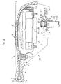
- Fig. 3 is a rear view of a steering wheel W of this embodiment
- Fig. 2 is a sectional view taken along the line II-II of Fig. 3.
- a steering wheel body 1 of the steering wheel W comprises an annular ring 2, a pad 3 disposed in the center of the ring 2, and three spokes 4 extending from the ring 2 to the pad 3.
- This embodiment can also be materialized in a steering wheel having two or not less than four spoke core bars.
- the ring 2 is constituted by a ring core bar 5 made of steel pipe, for example, and a sheath 7a covering it, while the spokes 4 are constituted by spoke core bars 6A, 6B, 6C made of lightweight die-cast metal such as aluminum alloy and a sheath 7b covering them.
- the sheaths 7a, 7b and the pad 3 are integrally made of soft synthetic resin (such as polyurethane foam).
- the steering wheel body 1 is assembled and fixed to a boss 8. This assembling structure will be described below in detail.
- a concave housing portion 11 enclosed by the sheath 7b.
- a membrane switch (not shown) and an air bag device generally indicated at 13.
- the membrane switch has upper and lower thin plates constituting a part of a horn switch circuit (not shown) so that depressing of the pad 3 brings the thin plates into contact with each other to sound a horn.
- the air bag device 13 comprises an air bag 14 stored in a folded state, an inflator 15 for filling the air bag 14 with gas for expansion, and a bag holder 16 on which the air bag 14 and the inflator 15 are held and fixed.
- the bag holder 16 is fixed to the spoke core bar 6A or the like with screws 17 as shown in Fig. 2, for example.
- the present invention can also be materialized in a steering wheel of the type that has a shock absorbing member instead of the air bag device 13.
- the boss 8 is integral with the steering wheel body 1. Namely, the boss 8 is connected to the right and left spoke core bars 6B, 6C through connecting portions 21; however, the boss 8 is located below the ring core bar 5 and the spoke core bars 6B, 6C.
- the spoke core bars 6B, 6C are connected to the remaining spoke core bar 6A (adjacent to a driver) by means of sub-connecting portions 22. Due to this structure, the spoke core bars 6A - 6C, the ring core bar 5 and the boss 8 are firmly connected to one another, and a relatively large opening 23 is defined by the boss 8, the connecting portions 21 and the auxiliary connecting portions 22 on the driver side of the boss 8. Further, the spoke core bars 6B, 6C are connected to each other by means of a support bar 24 (see Fig. 2) so as to secure stability when the air bag 14 is inflated.
- the connecting portions 21, the auxiliary connecting portions 22 and the support bar 24 are made of die-cast aluminum like the spoke core bars 6A - 6C.
- a plastic lower cover (not shown) is provided to enclose the underside of the steering wheel body 1.
- a steering shaft 30 is formed at a distal end portion thereof with a serration 31 having a predetermined number of (approx. thirty, in general) teeth 31a, and an annular groove 32 constituting a constricted portion is formed in a vertically middle portion of the serration 31.
- the steering shaft 30 may be formed with the annular groove 32 partially along the circumference instead of being formed along the entire circumference.
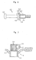
- the boss 8 comprises a tabular boss plate 33, a steel cylindrical portion 34 fixed by welding to the inner periphery of a through hole formed in the center of the plate 33, and a yoke portion 35 formed in an upper portion of the cylindrical portion 34 so as to be generally C-shaped in plan.
- the extreme edge of the boss plate 33 is partially embedded in the spoke core bars 6A - 6C. Owing to this embedding, the boss 8 and the spoke core bars 6A - 6C are connected to each other.
- the C-shaped yoke portion 35 is formed approximately at both ends thereof with through holes 36, 37 having different inside diameters, respectively.
- the through hole 36 of smaller diameter is formed with an internal thread.
- the cylindrical portion 34 is formed at an inner peripheral surface thereof with a serration 38 corresponding to the serration 31 of the steering shaft 30.
- the cylindrical portion 34 is fitted on the end of the steering shaft 30 in such a manner that the serrations 31, 38 mesh with each other.
- a bolt 41 is inserted into the through holes 36, 37 and screwed particularly in the through hole 36 of smaller diameter.
- the bolt 41 includes a shaft 42 and a head 43, the shaft 42 being formed on one end portion thereof with an external thread.
- the shaft 42 is constituted by a general shaft portion 44 located on the external thread side and an extended shaft portion 45, and an enlarged diameter portion 46 is integrally formed between the general shaft portion 44 and the extended shaft portion 45.
- the extended shaft portion 45 and the enlarged diameter portion 46 may be dispensed with.
- a washer 48 is interposed between the collar 47 and the enlarged diameter portion 46. Therefore, the collar 47 is kept immovably fixed between the enlarged diameter portion 46 (washer 48) and the external thread. Alternatively, the washer 48 may be dispensed with.
- the cylindrical portion 34 is fitted in the through hole of the boss plate 33 and welding is performed to couple the two, thereby to constitute the boss 8.
- the ring core bar 5 is formed separately.
- the thus-obtained boss 8 and ring core bar 5 are set in a die (not shown).
- a cavity for forming the spoke core bars 6A - 6C and the like (including the connecting portions 21, the sub-connecting portions 22 and the support bar 24) is defined to be isolated from the yoke portion 35 due to the presence of the boss plate 33.
- molten aluminum is poured into the cavity to fill it up.
- die-cast aluminum is molded in such a manner that the extreme edge of the boss plate 33 is embedded therein, with the result that the spoke core bars 6A - 6C and the like are obtained.
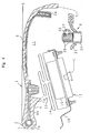
- the membrane switch and the air bag device 13 are inserted through the opening 23 defined by the boss 8, the connecting portions 21 and the sub-connecting portions 22, and the bag holder 16 of the air bag device 13 is fixed to the spoke core bar 6A and the like by means of screws 17 (see Figs. 2 and 5).
- the opening 23 is relatively large, the air bag device 13 can be easily mounted in the steering wheel main body 1.
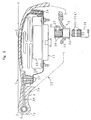
- the boss 8 integrated with the steering wheel body 1 is fitted on the distal end of the steering shaft 30 in such a manner that the serration 31 of the steering shaft 30 and the serration 38 formed in the cylindrical portion 34 of the boss 8 mesh with each other.
- the bolt 41 integrated with the collar 47 is inserted into the through holes 37, 36 of the yoke portion 35, as shown in Fig. 8.
- the collar 47 is so designed as to be inserted only through the through hole 37 of larger diameter but it may be made longer so as to be partially inserted into the other through hole 36. In this case, however, it is necessary to provide a projection or the like to ensure a sufficient thread tolerance.
- the external thread of the bolt 41 is screwed in the through hole 36 formed with the internal thread. This screwing causes the serrations 31, 38 to further mesh with each other (or come into surface contact with each other) and the yoke portion 35 to be tightened as shown in Figs.
- the boss 8 and hence the steering wheel W are restrained from moving in the direction of rotation with respect to the steering shaft 30.
- the collar 47 on the outer periphery of the bolt 41 is inserted into (fitted in) the annular groove 32 of the steering shaft 30, so that the boss 8 and hence the steering wheel W are restrained from moving vertically. Owing to these restraints, the steering wheel W can be fixed on the steering shaft 30.
Landscapes
- Engineering & Computer Science (AREA)
- Mechanical Engineering (AREA)
- Chemical & Material Sciences (AREA)
- Combustion & Propulsion (AREA)
- Transportation (AREA)
- Steering Controls (AREA)
Description
- This invention relates to a steering wheel.
- A steering wheel comprises an annular ring, a pad disposed in the center of the ring and spokes extending from the ring to the pad. A ring core bar is embedded in the ring, while spoke core bars are embedded in the spokes. In this case, the ring and spoke core bars are covered with a sheath made of polyurethane foam, for example. A distal end of the spoke core bars are connected to a boss plate (boss) below the pad. The boss has a through hole with a serration on an inner periphery thereof so that it is fitted on an end of a steering shaft formed with the same serration and mounted thereon by tightening a nut.
- In the steering wheel with such construction, the spoke core bars and hence the boss integrated with a steering wheel main body are mounted on the steering shaft by tightening the nut, and thereafter an air bag device and the like are attached and the pad is fitted to cover them.
- On the other hand, recently there has been proposed a steering wheel of the type that a sheath and a pad are formed integrally to eliminate a border line between the sheath and pad (Japanese Utility Model Unexamined Publication No. 2-133955, for example). According to such technology, since the sheath and the pad can be integrated, it is possible to improve the design.
- However, according to the above technology, it is very difficult to tighten a nut after fitting the steering wheel main body on the end of the steering shaft. This is because the top of the steering wheel main body is not open since the pad is integral with the sheath.
- In contrast, it can be thought to adopt a yoke type boss so as to tighten the steering wheel from the side thereof with a bolt. Namely, the yoke type boss includes a cylindrical portion having a serration corresponding to the serration of the steering shaft formed on an inner periphery thereof and a yoke portion formed integrally with the cylindrical portion. The yoke portion is of generally C-shape in plan and is formed with through holes substantially at both ends thereof. At least one of the through holes is formed with an internal thread. Meanwhile, the steering shaft is formed with a constricted portion in the position corresponding to the through holes.
- By screwing the bolt into the through holes, the serrations are caused to mesh with each other and the yoke portion is tightened. This contributes to restraining the steering wheel from moving in the direction of rotation. At the same time, a shaft of the bolt is fitted in the constricted portion. This contributes to restraining the steering wheel from moving in the vertical direction as well. In consequence, according to such technology, even in the steering wheel in which the pad is integral with the sheath, the mounting operation can be performed relatively easily.
- However, in the above conventional technology, it is designed that the shaft of the bolt by which the steering wheel and the steering shaft are connected, is fitted directly in the constricted portion of the steering shaft. Therefore, when external stress is applied to the steering wheel, stress strain between the steering wheel and the steering shaft is transmitted directly to the bolt. As a result, there has been an apprehension that after assembling the steering wheel, the tightened bolt might be loosened or the threaded portion (internal or external thread) might be damaged.
- Incidentally, in the field of steering wheels, it is typical that spoke core bars and the like are made of die-cast aluminum so as to make the steering wheel lighter as a whole. In this case, it is necessary to connect aluminum spoke core bars to an iron boss. In the case of the usual boss (formed in a generally cylindrical shape), a preformed boss is set in a mold for die casting as an insert and, in this condition, molten aluminum is poured into the mold. Then, the core bars can be formed in such a manner that the periphery (extreme edge) of the boss is connected to spoke core bars, that is, the extreme edge of the boss is embedded in aluminum to form core bars.
- However, such technology could not be applied as it was in cases where the above yoke type boss was formed in a generally C-shaped in plan so as to allow molten aluminum to go around through an opening of the yoke portion.
- The above conventional technology, however, needed to have such a configuration in that it prevents molten aluminum from going around to the inside of the boss when casting the spoke core bars. For this reason, the shape itself was limited, resulting in low degree of freedom in its shape.
- Particularly, in cases where the yoke type boss was adopted (which has a yoke portion for bolt tightening formed on the cylindrical portion to be generally C-shaped in plan), the above die casting technology could not be applied as it was. This is because the yoke portion of the boss is generally C-shaped in plan, so that molten aluminum goes around through the opening of the yoke portion at the time of die casting.
- On the other hand, Japanese Patent Unexamined Publication No. 60-60065 discloses a technology in which spoke core bars are connected to each other by means of a connecting portion with a through hole in which the boss is to be fitted. Fixing of the boss is performed by caulking a peripheral edge of the through hole of the connecting portion. According to this technology, the boss can be fixed to the connecting portion after connecting the spoke core bars to each other, and therefore degree of freedom in shape of the boss itself can be further increased.
- However, in this technology, since the peripheral edge of the through hole of the connecting portion is simply caulked from the outside, there is the risk of easy rotation of the boss, resulting in difficulty in ensuring sufficient joining strength between the boss and the core bars. This gives rise to a problem with respect to stability of mounting condition.
- GB-A-2 058 694 describes a steering wheel which has a central hub portion formed together with spokes. Into a central hole with an inner serration of this hub portion, a boss is inserted in axial direction of the steering wheel and interlocking with the steering wheel by means of serrations on its outer periphery. The boss and the hub portion of the steering wheel are fixed to the steering shaft by means of a nut screwed on the steering shaft in an axial direction thereof.
- Finally, EP-A-0685379 describes a steering wheel comprising a boss adapted to be fitted on a steering shaft having a serration composed of a plurality of teeth formed on an outer periphery thereof, said boss including a cylindrical portion and a yoke portion provided integral with said cylindrical portion and having through holes formed substantially at both ends thereof, at least one of said through holes being formed with an internal thread. A bolt with an external thread is adapted to be screwed into said through holes so as to fix the boss on the steering shaft.
- An object of the present invention is to provide a steering wheel which is capable, in a steering wheel of the type that a sheath covering ring and spoke core bars is formed integrally with a pad, of improving the working property when assembling as well as of ensuring the stability of mounting condition.
- Another object of the invention is to provide a steering wheel of the type that a sheath covering ring and spoke core bars are formed integrally with a pad and a yoke type boss is adopted, which is capable of reducing weight by the use of spoke core bars made of die-cast aluminum while making direct connection between the boss and die-cast aluminum.
- These objects are solved with a steering wheel according to
claim - According to the invention, there is provided a steering wheel comprising a boss adapted to be fitted on a steering shaft having a serration made up of a plurality of teeth formed on an outer periphery thereof. The boss includes a cylindrical portion with a serration corresponding to the serration of the steering shaft on an inner periphery thereof and a yoke portion integral with the cylindrical portion and having through holes substantially at both ends thereof, at least one of the through holes being formed with an internal thread. The steering wheel includes a steering wheel body having a ring core bar, spoke core bars, sheaths covering the core bars, and a pad formed integrally with the sheaths and located in a substantially central upper portion of a ring. Part of the spoke core bars are connected to the boss. A bolt with an external thread formed at least approximately on an end thereof is screwed into the through holes so as to fix the boss, to which the steering wheel body is connected, on the steering shaft. At least the spoke core bars are made of die-cast aluminum. The boss comprises a boss body including the cylindrical portion and the yoke portion and a boss plate fixed by welding to the boss body and having a larger area than the yoke portion, and the extreme edge of the boss plate is embedded in the spoke core bars.
- Further according to the invention, there is provided a steering wheel comprising a boss adapted to be fitted on a steering shaft having a serration made up of a plurality of teeth formed on an outer periphery thereof, the boss including a cylindrical portion with a serration corresponding to the serration of the steering shaft on an inner periphery thereof and a yoke portion provided integral with the cylindrical portion and having through holes substantially at both ends thereof. At least one of the through holes is formed with an internal thread. A steering wheel body is provided and includes a ring core bar, spoke core bars, sheaths covering the core bars, and a pad formed integrally with the sheaths and located in a substantially central upper portion of a ring. Part of the spoke core bars are connected to the boss, wherein a bolt with an external thread formed at least approximately on an end thereof is screwed into the through holes so as to fix the boss, to which the steering wheel body is connected, on the steering shaft, and at least the spoke core bars are made of die-cast aluminum. The boss comprises a boss body including the cylindrical portion and the yoke portion and a flange formed integrally with the boss body and having a larger area than the yoke portion, and the flange is embedded in a connecting portion connected to the spoke core bars.
- Incidentally, in the text of this specification, "vertical direction of steering wheel" does not necessarily mean the vertical direction of the steering wheel in a state of being mounted on a vehicle, but means the axial direction of the steering shaft.
- In accordance with the present invention, the boss connected with the steering wheel body is fitted on the steering shaft having the serration made up of plural teeth formed on the outer periphery thereof in such a manner that the serration formed on the inner periphery of the cylindrical portion of the boss meshes with the serration of the steering shaft. Then the bolt is screwed into the through holes of the yoke portion. This screwing causes the serrations to further mesh with each other and the yoke portion to be tightened, so that the steering wheel is restrained from moving in the direction of rotation with respect to the steering shaft. Due to adoption of a yoke type boss, the steering wheel can be mounted relatively easily on the steering shaft even in cases where the pad is formed integrally with the sheath.
- In the present invention, the boss is formed by welding and fixing the boss plate having a larger area than the yoke portion to the boss body including the cylindrical portion and the yoke portion. When casting the core bars from aluminum, the boss plate serves as a seal in the die to restrain molten aluminum from going around to the inside of the boss through the opening of the yoke portion. Therefore, the extreme edge of the boss plate is embedded in the die-cast aluminum spoke core bars obtained by casting, thereby making it possible to obtain the integrated boss and core bars without fail.
- According to the present invention, the boss having at least a generally cylindrical shape is fixedly fitted on the steering shaft. A plurality of spoke core bars extending from the annular ring core bar toward approximately the center thereof are connected to one another by means of the connecting portion formed integrally with the spoke core bars. Further, the connecting portion is connected to the boss as well. The spoke core bars and the connecting portion are made of die-cast aluminum, which contributes to making the whole steering wheel lightweight.
- Accordingly, the present invention exhibits an excellent effect that, in a steering wheel of the type that a sheath covering ring and spoke core bars is formed integrally with a pad, the working property during assembly can be improved and the stability of mounting condition can be ensured.
- The present invention also exhibits an outstanding effect that, in a steering wheel of the type that a sheath covering ring and spoke core bars is formed integrally with a pad and a yoke type boss, it can be made lightweight by the spoke core bars made of die-cast aluminum and direct connection between the boss and die-cast aluminum can be ensured.
- Further, the present invention exhibits an excellent effect that, in a steering wheel of the type that at least the spoke core bars are made of die-cast aluminum so as to make the steering wheel lightweight and a boss structure thereof, the degree of freedom in shape of the boss can be increased and the stability of mounting condition can be ensured.
-
- Fig. 1 is a sectional view showing essential portions of a steering wheel mounting structure according to a first embodiment of the invention;
- Fig. 2 is a sectional view taken along the line II-II of Fig. 3;
- Fig. 3 is a rear view of a steering wheel;
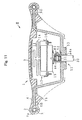
- Fig. 4 is a sectional view of a steering wheel body and the like showing a manner of installing an air bag device and the like;
- Fig. 5 is a sectional view for explanation of a process for mounting the steering wheel on a steering shaft;
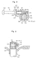
- Fig. 6 is a sectional view of a bolt of a steering wheel;
- Fig. 7 is a vertical sectional view showing a construction of a boss of a steering wheel;
- Fig. 8 is a sectional view of the boss and the like showing a manner of threadedly engaging the bolt;
- Fig. 9 is a vertical sectional view showing essential portions of a steering wheel mounting structure;
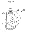
- Fig. 10 is a perspective view of a boss according to a second embodiment of the invention;
- Fig. 11 is a sectional view of a steering wheel of the invention;
- Fig. 12 is a sectional view showing the boss and a structure of a connecting portion of the invention;
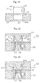
- Fig. 13 is a fragmentary sectional view of a die for forming the connecting portion and the like;
- Fig. 14 is a fragmentary sectional view showing a state in which a cavity is filled up with molten aluminum;
- Fig. 15 is a sectional view of a steering wheel boss structure according to an unclaimed example of the invention;
- Fig. 16 is a sectional view of a steering wheel of Fig. 15;
- Fig. 17 is a perspective view of core bars and the like;
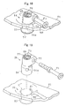
- Fig. 18 is a perspective view of the boss structure; and
- Fig. 19 is an exploded perspective view of the boss structure.
- Now, a first embodiment of the present invention will be described with reference to the drawings. Fig. 3 is a rear view of a steering wheel W of this embodiment, and Fig. 2 is a sectional view taken along the line II-II of Fig. 3.
- Referring to the drawings, a
steering wheel body 1 of the steering wheel W comprises anannular ring 2, apad 3 disposed in the center of thering 2, and threespokes 4 extending from thering 2 to thepad 3. This embodiment can also be materialized in a steering wheel having two or not less than four spoke core bars. Thering 2 is constituted by aring core bar 5 made of steel pipe, for example, and a sheath 7a covering it, while thespokes 4 are constituted by spoke core bars 6A, 6B, 6C made of lightweight die-cast metal such as aluminum alloy and a sheath 7b covering them. The sheaths 7a, 7b and thepad 3 are integrally made of soft synthetic resin (such as polyurethane foam). Thesteering wheel body 1 is assembled and fixed to aboss 8. This assembling structure will be described below in detail. - Meanwhile, below the
pad 3 is formed aconcave housing portion 11 enclosed by the sheath 7b. In theconcave housing portion 11 are disposed a membrane switch (not shown) and an air bag device generally indicated at 13. The membrane switch has upper and lower thin plates constituting a part of a horn switch circuit (not shown) so that depressing of thepad 3 brings the thin plates into contact with each other to sound a horn. - The
air bag device 13 comprises anair bag 14 stored in a folded state, aninflator 15 for filling theair bag 14 with gas for expansion, and abag holder 16 on which theair bag 14 and the inflator 15 are held and fixed. Thebag holder 16 is fixed to thespoke core bar 6A or the like withscrews 17 as shown in Fig. 2, for example. The present invention can also be materialized in a steering wheel of the type that has a shock absorbing member instead of theair bag device 13. - The
boss 8 is integral with thesteering wheel body 1. Namely, theboss 8 is connected to the right and left spoke core bars 6B, 6C through connectingportions 21; however, theboss 8 is located below thering core bar 5 and the spoke core bars 6B, 6C. - The spoke core bars 6B, 6C are connected to the remaining
spoke core bar 6A (adjacent to a driver) by means ofsub-connecting portions 22. Due to this structure, the spoke core bars 6A - 6C, thering core bar 5 and theboss 8 are firmly connected to one another, and a relativelylarge opening 23 is defined by theboss 8, the connectingportions 21 and the auxiliary connectingportions 22 on the driver side of theboss 8. Further, the spoke core bars 6B, 6C are connected to each other by means of a support bar 24 (see Fig. 2) so as to secure stability when theair bag 14 is inflated. The connectingportions 21, the auxiliary connectingportions 22 and thesupport bar 24 are made of die-cast aluminum like the spoke core bars 6A - 6C. - In this embodiment, a plastic lower cover (not shown) is provided to enclose the underside of the
steering wheel body 1. - Now, description will be given of the details of a mounting structure of the steering wheel W (features of this embodiment).
- As shown in Figs. 1, 2, 5 and 7, a steering
shaft 30 is formed at a distal end portion thereof with aserration 31 having a predetermined number of (approx. thirty, in general)teeth 31a, and anannular groove 32 constituting a constricted portion is formed in a vertically middle portion of theserration 31. Alternatively, the steeringshaft 30 may be formed with theannular groove 32 partially along the circumference instead of being formed along the entire circumference. Meanwhile, theboss 8 comprises atabular boss plate 33, asteel cylindrical portion 34 fixed by welding to the inner periphery of a through hole formed in the center of theplate 33, and ayoke portion 35 formed in an upper portion of thecylindrical portion 34 so as to be generally C-shaped in plan. The extreme edge of theboss plate 33 is partially embedded in the spoke core bars 6A - 6C. Owing to this embedding, theboss 8 and the spoke core bars 6A - 6C are connected to each other. The C-shapedyoke portion 35 is formed approximately at both ends thereof with throughholes hole 36 of smaller diameter is formed with an internal thread. Further, thecylindrical portion 34 is formed at an inner peripheral surface thereof with aserration 38 corresponding to theserration 31 of the steeringshaft 30. Thecylindrical portion 34 is fitted on the end of the steeringshaft 30 in such a manner that theserrations bolt 41 is inserted into the throughholes hole 36 of smaller diameter. - More specifically, as shown in Fig. 6, the
bolt 41 includes ashaft 42 and ahead 43, theshaft 42 being formed on one end portion thereof with an external thread. Theshaft 42 is constituted by ageneral shaft portion 44 located on the external thread side and anextended shaft portion 45, and anenlarged diameter portion 46 is integrally formed between thegeneral shaft portion 44 and theextended shaft portion 45. Alternatively, theextended shaft portion 45 and theenlarged diameter portion 46 may be dispensed with. - Further, in this embodiment, a
cylindrical collar 47 made of steel, like thebolt 41, is fitted on thegeneral shaft portion 44 in a position between the external thread and theenlarged diameter portion 46. In addition, awasher 48 is interposed between thecollar 47 and theenlarged diameter portion 46. Therefore, thecollar 47 is kept immovably fixed between the enlarged diameter portion 46 (washer 48) and the external thread. Alternatively, thewasher 48 may be dispensed with. - In this embodiment, as shown in Fig. 1, it is not the
general shaft portion 44 of thebolt 41 but thecollar 47 that is fitted in theannular groove 32 of the steeringshaft 30. In this way, theboss 8 is firmly fixed to the distal end of the steeringshaft 30 by means of thebolt 41, with the result that the steering wheel W is mounted on the steeringshaft 30. - Now, description will be given of how to mount the steering wheel W on the steering
shaft 30. - First, the
cylindrical portion 34 is fitted in the through hole of theboss plate 33 and welding is performed to couple the two, thereby to constitute theboss 8. On the other hand, thering core bar 5 is formed separately. - Subsequently, the thus-obtained
boss 8 andring core bar 5 are set in a die (not shown). At this time, a cavity for forming the spoke core bars 6A - 6C and the like (including the connectingportions 21, thesub-connecting portions 22 and the support bar 24) is defined to be isolated from theyoke portion 35 due to the presence of theboss plate 33. Then, molten aluminum is poured into the cavity to fill it up. In this case, owing to the presence of theboss plate 33, the molten aluminum is prevented from going around to theyoke portion 35 within the die. Therefore, as shown in Fig. 2, die-cast aluminum is molded in such a manner that the extreme edge of theboss plate 33 is embedded therein, with the result that the spoke core bars 6A - 6C and the like are obtained. - Succeedingly, as shown in Fig. 4, the membrane switch and the
air bag device 13 are inserted through theopening 23 defined by theboss 8, the connectingportions 21 and thesub-connecting portions 22, and thebag holder 16 of theair bag device 13 is fixed to thespoke core bar 6A and the like by means of screws 17 (see Figs. 2 and 5). In this case, since theopening 23 is relatively large, theair bag device 13 can be easily mounted in the steering wheelmain body 1. - Thereafter, as shown in Fig. 5, the
boss 8 integrated with thesteering wheel body 1 is fitted on the distal end of the steeringshaft 30 in such a manner that theserration 31 of the steeringshaft 30 and theserration 38 formed in thecylindrical portion 34 of theboss 8 mesh with each other. - In this condition, the
bolt 41 integrated with thecollar 47 is inserted into the throughholes yoke portion 35, as shown in Fig. 8. In this embodiment, thecollar 47 is so designed as to be inserted only through the throughhole 37 of larger diameter but it may be made longer so as to be partially inserted into the other throughhole 36. In this case, however, it is necessary to provide a projection or the like to ensure a sufficient thread tolerance. The external thread of thebolt 41 is screwed in the throughhole 36 formed with the internal thread. This screwing causes theserrations yoke portion 35 to be tightened as shown in Figs. 1 and 9, so that theboss 8 and hence the steering wheel W are restrained from moving in the direction of rotation with respect to the steeringshaft 30. Further, thecollar 47 on the outer periphery of thebolt 41 is inserted into (fitted in) theannular groove 32 of the steeringshaft 30, so that theboss 8 and hence the steering wheel W are restrained from moving vertically. Owing to these restraints, the steering wheel W can be fixed on the steeringshaft 30. - Description will now be given of a function and an effect of the first embodiment.
- (a) As described above, in this embodiment, the
cylindrical collar 47 is provided on the outer periphery of thebolt 41 and is fitted in theannular groove 32 of the steeringshaft 30. Therefore, after assembling, even in cases where the external stress is applied to the steering wheel W to give rise to strain stress between the steering wheel W and the steeringshaft 30, the stress is first transmitted to thecollar 47. This prevents the strain/stress from being transmitted directly to thebolt 41. Accordingly, it is possible to avoid a fear that the tightening portion of thebolt 41 is loosened or the thread portion (external or internal thread) is damaged. - (b) In this embodiment, the
collar 47 is immovably provided between the external thread and the enlarged diameter portion 46 (washer 48) of thebolt 41. Therefore, play between thecollar 47 and thebolt 41 is not permitted, thereby making it possible to further stabilize the mounting condition. - (c) Since the
collar 47 is made of the same material as thebolt 41, thecollar 47 itself is hardly deformed or damaged by the strain/stress. - (d) In this embodiment, the
bolt 41 has the extendedshaft portion 45 so as to make an overall length thereof longer. In consequence, thebolt 41 can be easily screwed from the side of the steering wheel W. As a result, the working property in mounting can be improved. - (e) As described above, in this embodiment, due to adoption of the
yoke type boss 8, the steering wheel W can be mounted on the steeringshaft 30 relatively easily even in cases where thepad 3 is formed integrally with the sheaths 7a, 7b. - (f) In this embodiment, the
boss 8 is formed by welding and fixing theboss plate 33 having a larger area than theyoke portion 35 to the boss body composed of thecylindrical portion 34 and theyoke portion 35. When casting the spoke core bars 6A - 6C from aluminum, theboss plate 33 serves as a seal in the die so that molten aluminum is prevented from going around to the inside of the boss 8 (cylindrical portion 34) through the opening of theyoke portion 35. Therefore, the extreme edge of theboss plate 33 can be embedded in the die-cast aluminum spoke core bars 6A - 6C obtained by casting, with the result that the steering wheel W in which theboss 8 and the core bars 6A - 6C are integral with each other can be obtained without fail. - (g) It is naturally possible to construct the spoke core bars 6A - 6C from die-cast aluminum, and therefore an overall weight of the steering wheel can be reduced.
- (h) In this embodiment, screwing of the
bolt 41 causes theserrations yoke portion 35 to be tightened, so that it is possible to restrain the steering wheel W from moving in the direction of rotation with respect to the steeringshaft 30. Further, since thebolt 41 is fitted in theannular groove 32 of the steeringshaft 30, it is possible to restrain theboss 8 and hence the steering wheel W from moving vertically. In consequence, the steering wheel W can be firmly fixed on the steeringshaft 30.
Now, a second embodiment of the present invention will be described with reference to Figs. 10 - 14. In the construction of this embodiment, the same components or members as those of the first embodiment are designated by the same reference numerals and explanation thereof is omitted. The following description lays special emphasis on differences from the first embodiment.
In contrast with the first embodiment in which theboss 8 comprises theboss plate 33 and the boss body (composed of thecylindrical portion 34 and the yoke portion 35), aboss 51 of this embodiment comprises, as shown in Fig. 10, aboss body 66 composed of acylindrical portion 64 and ayoke portion 65, and aflange 52 formed integrally with thecylindrical portion 64. Theflange 52 is formed in a non-circular shape.
Theboss 51 may be made by any method but it can be generally made by one of the methods including cold forging, hot forging, press working and machining or by a suitable combination of these methods. For instance, softened steel is roughly shaped with a die and then subjected to drilling, threading, slitting and the like, thereby making a boss. Incidentally, theserration 68 may be formed after molding die-cast aluminum to be described below. This makes it possible to prevent theserration 68 from being adversely affected by heat transfer at the time of casting.
In this embodiment, thecylindrical portion 64 is formed integrally with aflange portion 64a at the lowermost end thereof as well. Alternatively, theflange portion 64a may be dispensed with. The shapes of theflange 52 and theflange portion 64a are not limited to those of this embodiment.
As shown in Figs. 11, 12, a die-castaluminum connecting portion 53 is disposed around thecylindrical portion 64 in a position between theflange 52 and theflange portion 64a, and the connectingportion 53 is connected to the spoke core bars 6A - 6C. In other words, the connectingportion 53 is made of die-cast aluminum in the same manner as the spoke core bars 6A - 6C so as to be integral therewith.
Now, description will be given of the method of forming the spoke core bars 6A - 6C and the connectingportion 53 of the steering wheel W constructed as described above. As shown in Fig. 13, adie 54 consists of a first split die 55 and a second split die 56. The second split die 56 is formed with aconcave portion 57 for housing theyoke portion 65 and apositioning projection 58. On the other hand, the first split die 55 is formed integrally with apositioning pin 59 which faces thepositioning projection 58.
When forming the spoke core bars 6A - 6C and the connectingportion 53, as shown in Fig. 13, theyoke portion 65 of theboss 51 is set in theconcave portion 57 so as to be fitted on thepositioning projection 58, and thecylindrical portion 64 is so set as to be fitted on thepositioning pin 59, and thereafter, both split dies 55, 57 are fastened to each other. In this case, it is a matter of course to set thering core bar 5 in the die 54 as well, although this is not shown. Due to fastening of die, acavity 60 for forming the connectingportion 53 and the spoke core bars 6A - 6C is provided between the first and second split dies 55 and 56. Thecavity 60 is isolated from the yoke portion 65 (concave portion 57) due to presence of theflange 52 and the like.
Then, molten aluminum is poured into thecavity 60 to fill it up as shown in Fig. 14. In this case, owing to the presence of theflange 52, the molten aluminum is prevented from flowing to the yoke portion 65 (concave portion 57) within thedie 54. Therefore, as described above, the die-cast aluminum is molded around thecylindrical portion 64 with theflange 52 and theflange portion 64a embedded therein, with the result that the connectingportion 53, the spoke core bars 6A - 6C and the like are obtained.
Description will now be given of a function and an effect of the second embodiment. - (i) As described above, this embodiment basically has substantially the same function and effect as the first embodiment as well. In addition, in this embodiment, since the
flange 52 is an integral part of theboss body 66, welding or other like operations may be dispensed with. Therefore, it is possible to avoid warp of thecylindrical portion 64 and deformation of theserration 68 on the inner surface of thecylindrical portion 64 which might be caused otherwise by heat or the like at the time of welding. As a result, the trouble of machining the serration over again, attributed to the warp and deformation, can be avoided. - (j) In this embodiment, the
flange 52 is formed in a non-circular shape, and therefore, even when theflange 52 is embedded in the die-cast aluminum, theboss 51 can be restrained from moving in rotation with respect to the connectingportion 53 without fail. As a result, it is possible to avoid the problem attributable to the rotating movement.
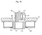
Description will now be given of an unclaimed example with reference to Figs. 15 - 19. Fig. 16 is a sectional view of a steering wheel W according to this example, and Fig. 17 is a perspective view showing core bar portions. In the construction of this example, the same components or members as those of the first embodiment are designated by the same reference numerals, and an explanation thereof is omitted. The following description lays special emphasis on differences from the first embodiment.
Aboss 28 is connected to spoke core bars 6A - 6C so as to be integral with asteering wheel body 1. Namely, as shown in Figs. 15, 17, theboss 28 is connected to the right and left spoke core bars 6B and 6C through a connectingportion 71. In other words, the right and left spoke core bars 6B, 6C are connected to each other by means of the connectingportion 71 which is in turn connected to theboss 28. In this example, theboss 28 is made of steel, while the connectingportion 71,sub-connecting portions 22 and asupport bar 24 are each made of die-cast aluminum similarly to the spoke core bars 6B, 6C.
In this example, as shown in Figs. 15, 19, a throughhole 72 is formed in substantially the central portion of the connectingportion 71. The throughhole 72 is formed integrally with acylinder portion 73 projecting downwardly. The throughhole 72 of this example, therefore, has a predetermined depth. Around the peripheral edge of the throughhole 72 is formed aconcave portion 84 by bending the connectingportion 71. Further, in the surface of the connectingportion 71 is formed aguide groove 71A for guiding abolt 91 toward the throughhole 72. Incidentally, disposed around thecylinder portion 73 is arelay spiral cable 86.
The throughhole 72 is so tapered as to be reduced in diameter towards its lower end. Into the throughhole 72 formed by thecylinder portion 73 is press-fitted acylindrical portion 74 of theboss 28. Thecylindrical portion 74 is also tapered at the beginning so as to be reduced in diameter towards its lower end (see Fig. 19), and the outer peripheral surface thereof corresponds to the inner peripheral surface of the throughhole 72. Further, thecylindrical portion 74 is formed in a portion of the outer peripheral surface thereof with a partially flattened detent 74a. The throughhole 72 is also formed with a detent (not shown) in a portion of the inner peripheral surface thereof corresponding to the detent 74a.
Description will now be given of how to mount the steering wheel W on the steeringshaft 30.
In the first place, aring core bar 5 is formed. Thisring core bar 5 is then set in a die (not shown). At this time, a cavity for forming the spoke core bars 6A - 6C and the like (including the connectingportion 71,sub-connecting portion 22 and the support bar 24) is defined in the die. Unlike the prior art, the boss is never set in the die of this example as an insert. Therefore, degree of freedom in shape of the cavity (hence the connectingportion 71, the spoke core bars 6A - 6C and the like) can be increased. Then, molten aluminum is poured into the cavity to fill it up. Thereafter, by virtue of the aluminum cooling and solidifying, the connectingportion 71 with the throughhole 72 and the spoke core bars 6A - 6C can be obtained.
Meanwhile, theboss 28 is formed separately by means of cold forging, hot forging, machining, press working or the like. Subsequently, the thus-obtainedboss 28 is press-fitted in the throughhole 72 in such a manner that the detent 74a meets the detent on the inner peripheral surface of the throughhole 72. That is to say, the detent 74a also serves as a kind of positioning means. Then, as shown in Fig. 15, the press-fittedboss 28 is increased in diameter such that the tapered end portion of thecylindrical portion 74 extending beyond the distal end of thecylinder portion 73 is subjected to caulking.
Succeedingly, a membrane switch and anair bag device 13 are mounted in thesteering wheel body 1 in the same manner as in the first embodiment. Thereafter, theboss 28 is fitted on the distal end of the steeringshaft 30 in the same manner as in the first embodiment. When screwing an external thread of thebolt 91 into a throughhole 76 formed with an internal thread, thebolt 91 is guided by theguide groove 71A, and therefore the screwing operation can be relatively easily performed even if the position of ayoke portion 75 is relatively low.
Now, description will be given of a function and an effect of this example. - (k) As described above, due to adoption of the
yoke type boss 28, the steering wheel W can be relatively easily mounted on the steeringshaft 30 even in cases where apad 3 is formed integrally with sheaths 7a, 7b. - (l) When obtaining the boss structure, the spoke core bars 6A - 6C and the connecting
portion 21 are first formed in the predetermined shape by die casting, thus making the steering wheel lightweight. At this time, the connectingportion 71 is formed with the tapered throughhole 72. Then, thecylindrical portion 74 of theboss 28 formed separately is press-fitted in the throughhole 72. Further, the distal end portion of thecylindrical portion 74 is increased in diameter by caulking. Due to this increase in diameter, theboss 28 is firmly fixed to the connectingportion 71.
As described above, unlike the prior art in which the spoke core bars were formed by die casting with the boss set in the die as an insert, it will do in this example to fix theboss 28 after forming the spoke core bars 6A - 6C and the like. Therefore, even if theboss 28 is of the type that has an opening (yoke type), the boss structure can be materialized without fail. Further, theboss 28 can be firmly fixed to the connectingportion 71 due to frictional force between theboss 28 and the inner peripheral surface of the throughhole 72 and an increase in diameter of the distal end of thecylindrical portion 74. In consequence, adoption of the spoke core bars 6A - 6C made of die-cast aluminum makes it possible to reduce the weight and increase the degree of freedom in shape of theboss 28. Further, it is possible to ensure the stability of mounting condition. - (m) Particularly, the
cylinder portion 73 is provided in a portion of the connectingportion 71. Therefore, the throughhole 72 has a predetermined depth, so that there can be ensured a sufficient contact surface with the boss 28 (cylindrical portion 74). In consequence, the frictional force can be increased, so that theboss 28 is fixed to the connectingportion 71 more firmly, thereby making it possible to further stabilize the mounting condition. - (n) Since the
pad 3 is formed integrally with the sheaths 7a, 7b, a space between thepad 3 and theboss 28 has relatively many restrictions. However, by forming theconcave portion 84 in the connectingportion 71, theyoke portion 75 is allowed to be positioned as low as possible. At the same time, thecylinder portion 73 is made to extend downwardly. This prevents the space above theboss 28 from being obstructed. As a result, it is also possible to effectively utilize the space.
Moreover, theguide groove 71A for guiding thebolt 91 is formed in the upper surface of the connectingportion 71. It is therefore possible to perform the screwing operation without difficulty even if theyoke portion 75 is positioned as low as possible, thereby making it possible to easily secure theboss 28. - (o) The boss 28 (cylindrical portion 74) is formed in a portion thereof with the detent 74a and the through
hole 72 is formed in the inner peripheral surface thereof with the detent. This contributes to restraining the rotation of theboss 28 relative to the connectingportion 71. It is therefore possible to secure theboss 28 to the connectingportion 71 more firmly.
Claims (2)
- A steering wheel comprising:a boss (8) adapted to be fitted on a steering shaft (30) having a serration (31) composed of a plurality of teeth (31a) formed on an outer periphery thereof, said boss (8) including a cylindrical portion (34) with a serration (38), corresponding to said serration (31) of the steering shaft, on an inner periphery thereof, and a yoke portion (35) provided integral with said cylindrical portion (34) and having through holes (36, 37) formed substantially at both ends thereof, at least one (36) of said through holes (36, 37) being formed with an internal thread;a steering wheel body (1) including a ring core bar (5), spoke core bars (6A, 6B, 6C), sheaths (7a, 7b) covering said core bars (5, 6A, 6B, 6C), and a pad (3) formed integrally with said sheaths (7a, 7b) and located in a substantially central upper portion of a ring (2), part of said spoke core bars (6A, 6B, 6C) being connected to said boss (8); anda bolt (41) with an external thread formed at least approximately on an end thereof being adapted to be screwed into said through holes (36, 37) so as to fix the boss (8), to which said steering wheel body (1) is connected, on said steering shaft (30), at least said spoke core bars (6A, 6B, 6C) being made of die-cast aluminum, and wherein said boss (8) comprises a boss body composed of said cylindrical portion (34) and said yoke portion (35), and a boss plate (33) fixed by welding to said boss body and having a larger area than said yoke portion (35), and the extreme edge of said boss plate (33) is embedded in said spoke core bars (6A, 6B, 6C).
- A steering wheel comprising:a boss (51) adapted to be fitted on a steering shaft (30) having a serration (31) composed of a plurality of teeth (31a) formed on an outer periphery thereof, said boss (51) including a cylindrical portion (64) with a serration (68), corresponding to said serration (31) of the steering shaft, on an inner periphery thereof, and a yoke portion (65) provided integral with said cylindrical portion (64) and having through holes (36, 37) formed substantially at both ends thereof, at least one (36) of said through holes (36, 37) being formed with an internal thread;a steering wheel body (1) including a ring core bar (5), spoke core bars (6A, 6B, 6C), sheaths (7a, 7b) covering said core bars (5, 6A, 6B, 6C), and a pad (3) formed integrally with said sheaths (7a, 7b) and located in a substantially central upper portion of a ring (2), part of said spoke core bars (6A, 6B, 6C) being connected to said boss (51); anda bolt (81) with an external thread formed at least approximately on an end thereof being adapted to be screwed into said through holes (36, 37) so as to fix the boss (51), to which said steering wheel body (1) is connected, on said steering shaft (30), at least said spoke core bars (6A, 6B, 6C) being made of die-cast aluminum, and wherein said boss (51) comprises a boss body (66) including said cylindrical portion (64) and said yoke portion (65), and a flange (64a, 52) formed integrally with said boss body (66) and having a larger area than said yoke portion (65), and said flange (64a, 52) is embedded in a connecting portion (53) connected to said spoke core bars (6A, 6B, 6C).
Applications Claiming Priority (7)
| Application Number | Priority Date | Filing Date | Title |
|---|---|---|---|
| JP03824196A JP3209076B2 (en) | 1996-02-26 | 1996-02-26 | Steering wheel mounting structure |
| JP3824196 | 1996-02-26 | ||
| JP5580496 | 1996-03-13 | ||
| JP5580596 | 1996-03-13 | ||
| JP5580596A JPH09240491A (en) | 1996-03-13 | 1996-03-13 | Steering wheel and boss structure thereof |
| JP8055804A JP3070471B2 (en) | 1996-03-13 | 1996-03-13 | Steering wheel |
| EP97100137A EP0791520B1 (en) | 1996-02-26 | 1997-01-07 | Steering wheel, mounting structure thereof and boss structure thereof |
Related Parent Applications (2)
| Application Number | Title | Priority Date | Filing Date |
|---|---|---|---|
| EP97100137A Division EP0791520B1 (en) | 1996-02-26 | 1997-01-07 | Steering wheel, mounting structure thereof and boss structure thereof |
| EP97100137.5 Division | 1997-01-07 |
Publications (3)
| Publication Number | Publication Date |
|---|---|
| EP1004496A2 EP1004496A2 (en) | 2000-05-31 |
| EP1004496A3 EP1004496A3 (en) | 2000-06-28 |
| EP1004496B1 true EP1004496B1 (en) | 2006-09-27 |
Family
ID=27289752
Family Applications (2)
| Application Number | Title | Priority Date | Filing Date |
|---|---|---|---|
| EP00105873A Expired - Lifetime EP1004496B1 (en) | 1996-02-26 | 1997-01-07 | Steering wheel, mounting structure thereof and boss structure thereof |
| EP97100137A Expired - Lifetime EP0791520B1 (en) | 1996-02-26 | 1997-01-07 | Steering wheel, mounting structure thereof and boss structure thereof |
Family Applications After (1)
| Application Number | Title | Priority Date | Filing Date |
|---|---|---|---|
| EP97100137A Expired - Lifetime EP0791520B1 (en) | 1996-02-26 | 1997-01-07 | Steering wheel, mounting structure thereof and boss structure thereof |
Country Status (4)
| Country | Link |
|---|---|
| US (3) | US5855145A (en) |
| EP (2) | EP1004496B1 (en) |
| AU (1) | AU683813B2 (en) |
| DE (2) | DE69711968T2 (en) |
Families Citing this family (18)
| Publication number | Priority date | Publication date | Assignee | Title |
|---|---|---|---|---|
| DE19616234C2 (en) * | 1996-04-15 | 1998-07-16 | Petri Ag | Device for fastening a hub on a shaft, in particular a steering wheel hub on a steering column |
| US6367351B2 (en) | 1998-01-13 | 2002-04-09 | Toyoda Gosei Co., Ltd. | Steering wheel |
| US6283501B1 (en) | 1997-09-29 | 2001-09-04 | Toyoda Gosei Co., Ltd. | Steering wheel |
| US6276865B1 (en) * | 1998-10-30 | 2001-08-21 | The Torrington Company | Steering column shaft clamp |
| FR2796892B1 (en) * | 1999-07-28 | 2001-10-19 | Sc2N Sa | SYSTEM FOR FIXING A CONTROL PANEL TO AN EASY IMPLEMENTATION STEERING COLUMN |
| US6568702B1 (en) * | 2000-02-04 | 2003-05-27 | Breed Automotive Technology, Inc. | No housing driver's air bag module |
| US6314833B1 (en) | 2000-05-31 | 2001-11-13 | Trw Inc. | Apparatus for attaching a vehicle steering wheel to a vehicle steering shaft |
| US6318756B1 (en) * | 2000-09-14 | 2001-11-20 | Trw Inc. | Apparatus for attaching a steering wheel to a steering shaft |
| JP3431012B2 (en) * | 2000-10-10 | 2003-07-28 | 豊田合成株式会社 | Steering wheel |
| DE20101868U1 (en) * | 2001-02-01 | 2001-06-21 | Trw Automotive Safety Sys Gmbh | Vehicle steering wheel |
| US6925714B2 (en) * | 2002-12-19 | 2005-08-09 | Delphi Technologies, Inc. | Upper steering shaft-assembly |
| US20060230873A1 (en) * | 2005-04-15 | 2006-10-19 | Takata-Petri Inc. | Steering wheel and method of manufacturing |
| US8661936B2 (en) * | 2006-01-31 | 2014-03-04 | Toyoda Gosei Co. Ltd. | Trim plate for steering wheel |
| US7891902B2 (en) * | 2007-06-19 | 2011-02-22 | Robotzone, Llc | Hobby servo shaft adapter |
| CN101939206B (en) * | 2009-04-07 | 2013-02-13 | 丰田自动车株式会社 | Shaft coupling structure |
| JP5964650B2 (en) * | 2012-05-14 | 2016-08-03 | 日本プラスト株式会社 | Steering wheel with finisher |
| FR3006400B1 (en) * | 2013-05-29 | 2015-06-19 | Zf Systemes De Direction Nacam Sas | SECURE ASSEMBLY OF TWO PIECES BY VISSAGE |
| US11011957B2 (en) | 2016-11-15 | 2021-05-18 | Robotzone, Llc | Servo shaft couplers |
Family Cites Families (41)
| Publication number | Priority date | Publication date | Assignee | Title |
|---|---|---|---|---|
| GB655837A (en) * | 1948-12-02 | 1951-08-01 | Bluemel Brothers Ltd | Improvements in or relating to steering wheels for motor road vehicles |
| FR997670A (en) * | 1949-09-23 | 1952-01-09 | Device for wedging two-arm steering wheels | |
| DE1015704B (en) * | 1956-03-08 | 1957-09-12 | Petri Lenkradwerk | Removable steering wheel for motor vehicles |
| DE1094610B (en) * | 1956-03-08 | 1960-12-08 | Petri Lenkradwerk | Removable steering wheel for motor vehicles |
| GB2058694A (en) * | 1979-09-17 | 1981-04-15 | Faul T L | Steering Wheel |
| GB2102092B (en) * | 1981-06-17 | 1985-04-03 | Rawcliffe Laurence Carl | Locking means |
| GB2101092A (en) * | 1981-06-24 | 1983-01-12 | Ashton Containers | A stackable box or tray |
| JPS606005A (en) * | 1983-06-24 | 1985-01-12 | Toshiba Corp | Overspeed trip for turbine |
| JPS6060065A (en) * | 1983-09-12 | 1985-04-06 | Toyoda Gosei Co Ltd | Steering wheel |
| JPS6060065U (en) | 1983-09-30 | 1985-04-26 | 富士通株式会社 | magnetic disk device |
| FR2557992B1 (en) * | 1984-01-06 | 1986-11-07 | Eckendorff Jean Pierre | DEVICE FOR ADJUSTING THE ANGULAR POSITION OF A CALE MEMBER ROTATING WITH A SHAFT, ESPECIALLY A STEERING WHEEL FOR A MOTOR VEHICLE ASSOCIATED WITH A STEERING COLUMN. |
| US4685848A (en) * | 1985-02-12 | 1987-08-11 | Langer Alfred C | Gear headed fastener and drive tool structure |
| JPS62149552A (en) * | 1985-08-29 | 1987-07-03 | Toyoda Gosei Co Ltd | Vibration preventing device for steering wheel |
| CA1271112A (en) * | 1986-01-14 | 1990-07-03 | Nihon Plast Co., Ltd. | Steering wheel |
| JPS63134368A (en) * | 1986-11-22 | 1988-06-06 | Toyoda Gosei Co Ltd | Steering wheel installing structure |
| DE3700968A1 (en) * | 1987-01-15 | 1988-08-04 | Bosch Gmbh Robert | TENSIONING DEVICE FOR AXIAL CLAMPING OF A TOOL, IN PARTICULAR A DISC |
| FR2614951B1 (en) * | 1987-05-05 | 1989-08-25 | Laurencot Jean | INACCESSIBLE AXIS TIGHTENING ASSEMBLY |
| IT1210743B (en) * | 1987-05-19 | 1989-09-20 | Fiat Auto Spa | DEVICE FOR THE CORRECT POSITIONING OF THE LOWER SHAFT STEERING CONTROL TO THE PINION OF THE STEERING BOX AND TO THE UPPER SHAFT |
| JPH0545588Y2 (en) * | 1988-08-08 | 1993-11-22 | ||
| JPH02133955A (en) * | 1988-11-15 | 1990-05-23 | Mitsubishi Electric Corp | Semiconductor integrated circuit device |
| JPH02133955U (en) | 1989-04-13 | 1990-11-07 | ||
| US5267486A (en) * | 1989-11-30 | 1993-12-07 | Toyoda Gosei Co., Ltd. | Steering wheel with pad |
| JP2559893B2 (en) * | 1990-08-09 | 1996-12-04 | 日本プラスト株式会社 | Steering wheel |
| US5144861A (en) * | 1990-03-19 | 1992-09-08 | Nihon Plast Co., Ltd. | Steering wheel construction |
| IT1240545B (en) * | 1990-09-11 | 1993-12-17 | Gallino Componenti Plastici S.P.A. | COUPLING DEVICE BETWEEN THE HUB OF A MOTOR VEHICLE STEERING WHEEL AND THE RELATIVE STEERING COLUMN |
| FR2675106B1 (en) * | 1991-04-10 | 1993-08-13 | Ecia Equip Composants Ind Auto | SECURITY TIGHTENING DEVICE OF A MALE MEMBER IN A CALIPER OF A FEMALE MEMBER, IN PARTICULAR USE FOR CONNECTING TWO PORTIONS OF A STEERING COLUMN OF A MOTOR VEHICLE. |
| JP2733150B2 (en) * | 1991-06-26 | 1998-03-30 | 株式会社河合楽器製作所 | Automatic piano playing method and apparatus |
| JPH06285607A (en) * | 1993-04-07 | 1994-10-11 | Toyoda Gosei Co Ltd | Manufacture of core metal for steering wheel |
| GB2282574B (en) * | 1993-10-05 | 1997-01-15 | Autoliv Dev | A steering wheel |
| US5510747A (en) * | 1993-11-30 | 1996-04-23 | Siliconix Incorporated | Gate drive technique for a bidirectional blocking lateral MOSFET |
| FR2715906B1 (en) * | 1994-02-04 | 1996-04-26 | Ecia Equip Composants Ind Auto | Device for fixing a member to a steering shaft, in particular of a motor vehicle. |
| DE4419078A1 (en) * | 1994-05-31 | 1995-12-07 | Trw Repa Gmbh | Fastening device for a vehicle steering wheel |
| US5588337A (en) * | 1994-11-17 | 1996-12-31 | General Motors Corporation | Motor vehicle steering column |
| US5536106A (en) * | 1995-02-09 | 1996-07-16 | General Motors Corporation | Connection between a shaft and a hub |
| JP3633050B2 (en) * | 1995-08-31 | 2005-03-30 | 豊田合成株式会社 | Steering wheel mounting structure |
| JPH09123919A (en) * | 1995-08-31 | 1997-05-13 | Toyoda Gosei Co Ltd | Mounting structure for steering wheel |
| US5692770A (en) * | 1995-09-15 | 1997-12-02 | Breed Automotive Technology, Inc. | Modular steering wheel and airbag combination |
| DE29516623U1 (en) * | 1995-10-20 | 1996-01-25 | Trw Repa Gmbh | Fastening a vehicle steering wheel to a steering shaft |
| JPH09132149A (en) * | 1995-11-10 | 1997-05-20 | Toyoda Gosei Co Ltd | Attaching structure of steering wheel |
| US5617763A (en) * | 1995-11-24 | 1997-04-08 | General Motors Corporation | Steering wheel for motor vehicle |
| JP3204099B2 (en) * | 1996-07-01 | 2001-09-04 | 豊田合成株式会社 | Steering wheel |
-
1996
- 1996-12-30 AU AU76521/96A patent/AU683813B2/en not_active Ceased
-
1997
- 1997-01-07 EP EP00105873A patent/EP1004496B1/en not_active Expired - Lifetime
- 1997-01-07 DE DE69711968T patent/DE69711968T2/en not_active Expired - Fee Related
- 1997-01-07 EP EP97100137A patent/EP0791520B1/en not_active Expired - Lifetime
- 1997-01-07 DE DE69736749T patent/DE69736749T2/en not_active Expired - Fee Related
- 1997-02-05 US US08/795,793 patent/US5855145A/en not_active Expired - Lifetime
-
1998
- 1998-10-20 US US09/175,463 patent/US5950499A/en not_active Expired - Lifetime
-
1999
- 1999-06-28 US US09/340,049 patent/US6079291A/en not_active Expired - Fee Related
Also Published As
| Publication number | Publication date |
|---|---|
| EP1004496A2 (en) | 2000-05-31 |
| EP0791520A1 (en) | 1997-08-27 |
| US6079291A (en) | 2000-06-27 |
| DE69736749D1 (en) | 2006-11-09 |
| AU7652196A (en) | 1997-09-04 |
| DE69711968D1 (en) | 2002-05-23 |
| AU683813B2 (en) | 1997-11-20 |
| US5855145A (en) | 1999-01-05 |
| DE69736749T2 (en) | 2007-08-16 |
| US5950499A (en) | 1999-09-14 |
| DE69711968T2 (en) | 2002-08-29 |
| EP0791520B1 (en) | 2002-04-17 |
| EP1004496A3 (en) | 2000-06-28 |
Similar Documents
| Publication | Publication Date | Title |
|---|---|---|
| EP1004496B1 (en) | Steering wheel, mounting structure thereof and boss structure thereof | |
| US5868041A (en) | Reduced vibration shock absorbing deformable steering wheel | |
| US6367351B2 (en) | Steering wheel | |
| US4920821A (en) | Steering wheel for vehicle | |
| US5720494A (en) | Steering wheel with air bag device | |
| US6095552A (en) | Steering wheel with an integral pad portion | |
| EP1134144A1 (en) | Core bar for steering wheels | |
| US5476022A (en) | Steering wheel core with improved spoke | |
| US6126193A (en) | Steering wheel | |
| JP3209076B2 (en) | Steering wheel mounting structure | |
| JP3070471B2 (en) | Steering wheel | |
| EP1195313B1 (en) | Tilt steering apparatus | |
| JP3275843B2 (en) | Steering wheel | |
| JPH09240491A (en) | Steering wheel and boss structure thereof | |
| JP3114928B2 (en) | Core | |
| JP3327163B2 (en) | Steering wheel | |
| JPH11198818A (en) | Steering wheel | |
| JPS6213233B2 (en) | ||
| JP3235469B2 (en) | Steering wheel | |
| JP2001080528A (en) | Fixing device for steering gear box | |
| JPH08230684A (en) | Steering wheel | |
| JPH046589B2 (en) | ||
| JPH09286340A (en) | Steering wheel | |
| JPH08207782A (en) | Steering wheel structure for automobile | |
| JPH046590B2 (en) |
Legal Events
| Date | Code | Title | Description |
|---|---|---|---|
| PUAI | Public reference made under article 153(3) epc to a published international application that has entered the european phase |
Free format text: ORIGINAL CODE: 0009012 |
|
| PUAL | Search report despatched |
Free format text: ORIGINAL CODE: 0009013 |
|
| AC | Divisional application: reference to earlier application |
Ref document number: 791520 Country of ref document: EP |
|
| AK | Designated contracting states |
Kind code of ref document: A2 Designated state(s): DE FR GB |
|
| RIC1 | Information provided on ipc code assigned before grant |
Free format text: 7B 62D 1/04 A, 7B 62D 1/10 B |
|
| AK | Designated contracting states |
Kind code of ref document: A3 Designated state(s): DE FR GB |
|
| 17P | Request for examination filed |
Effective date: 20000508 |
|
| RIC1 | Information provided on ipc code assigned before grant |
Free format text: 7B 62D 1/04 A |
|
| RIN1 | Information on inventor provided before grant (corrected) |
Inventor name: MIZUNO, TAKANORI Inventor name: SAKANE, KATSUNOBU Inventor name: YAMAMOTO, HITOSHI Inventor name: NAGATA, ATSUSHI Inventor name: TAKAMORI, TETSUVA Inventor name: HOSOI, AKIO |
|
| AKX | Designation fees paid |
Free format text: DE FR GB |
|
| GRAP | Despatch of communication of intention to grant a patent |
Free format text: ORIGINAL CODE: EPIDOSNIGR1 |
|
| RIN1 | Information on inventor provided before grant (corrected) |
Inventor name: YAMAMOTO, HITOSHI Inventor name: SAKANE, KATSUNOBU Inventor name: MIZUNO, TAKANORI Inventor name: TAKAMORI, TETSUYA Inventor name: NAGATA, ATSUSHI Inventor name: HOSOI, AKIO |
|
| GRAS | Grant fee paid |
Free format text: ORIGINAL CODE: EPIDOSNIGR3 |
|
| GRAA | (expected) grant |
Free format text: ORIGINAL CODE: 0009210 |
|
| AC | Divisional application: reference to earlier application |
Ref document number: 0791520 Country of ref document: EP Kind code of ref document: P |
|
| AK | Designated contracting states |
Kind code of ref document: B1 Designated state(s): DE FR GB |
|
| REG | Reference to a national code |
Ref country code: GB Ref legal event code: FG4D |
|
| REF | Corresponds to: |
Ref document number: 69736749 Country of ref document: DE Date of ref document: 20061109 Kind code of ref document: P |
|
| ET | Fr: translation filed | ||
| PLBE | No opposition filed within time limit |
Free format text: ORIGINAL CODE: 0009261 |
|
| STAA | Information on the status of an ep patent application or granted ep patent |
Free format text: STATUS: NO OPPOSITION FILED WITHIN TIME LIMIT |
|
| 26N | No opposition filed |
Effective date: 20070628 |
|
| PGFP | Annual fee paid to national office [announced via postgrant information from national office to epo] |
Ref country code: DE Payment date: 20080104 Year of fee payment: 12 Ref country code: GB Payment date: 20080102 Year of fee payment: 12 |
|
| PGFP | Annual fee paid to national office [announced via postgrant information from national office to epo] |
Ref country code: FR Payment date: 20080108 Year of fee payment: 12 |
|
| GBPC | Gb: european patent ceased through non-payment of renewal fee |
Effective date: 20090107 |
|
| PG25 | Lapsed in a contracting state [announced via postgrant information from national office to epo] |
Ref country code: DE Free format text: LAPSE BECAUSE OF NON-PAYMENT OF DUE FEES Effective date: 20090801 |
|
| REG | Reference to a national code |
Ref country code: FR Ref legal event code: ST Effective date: 20091030 |
|
| PG25 | Lapsed in a contracting state [announced via postgrant information from national office to epo] |
Ref country code: GB Free format text: LAPSE BECAUSE OF NON-PAYMENT OF DUE FEES Effective date: 20090107 |
|
| PG25 | Lapsed in a contracting state [announced via postgrant information from national office to epo] |
Ref country code: FR Free format text: LAPSE BECAUSE OF NON-PAYMENT OF DUE FEES Effective date: 20090202 |