EP1004059B1 - Method for detecting malfunctions of a first relay - Google Patents
Method for detecting malfunctions of a first relay Download PDFInfo
- Publication number
- EP1004059B1 EP1004059B1 EP98951166A EP98951166A EP1004059B1 EP 1004059 B1 EP1004059 B1 EP 1004059B1 EP 98951166 A EP98951166 A EP 98951166A EP 98951166 A EP98951166 A EP 98951166A EP 1004059 B1 EP1004059 B1 EP 1004059B1
- Authority
- EP
- European Patent Office
- Prior art keywords
- relay
- switching
- malfunction
- relays
- detected
- Prior art date
- Legal status (The legal status is an assumption and is not a legal conclusion. Google has not performed a legal analysis and makes no representation as to the accuracy of the status listed.)
- Expired - Lifetime
Links
Images
Classifications
-
- G—PHYSICS
- G01—MEASURING; TESTING
- G01R—MEASURING ELECTRIC VARIABLES; MEASURING MAGNETIC VARIABLES
- G01R31/00—Arrangements for testing electric properties; Arrangements for locating electric faults; Arrangements for electrical testing characterised by what is being tested not provided for elsewhere
- G01R31/327—Testing of circuit interrupters, switches or circuit-breakers
- G01R31/3277—Testing of circuit interrupters, switches or circuit-breakers of low voltage devices, e.g. domestic or industrial devices, such as motor protections, relays, rotation switches
- G01R31/3278—Testing of circuit interrupters, switches or circuit-breakers of low voltage devices, e.g. domestic or industrial devices, such as motor protections, relays, rotation switches of relays, solenoids or reed switches
-
- H—ELECTRICITY
- H01—ELECTRIC ELEMENTS
- H01H—ELECTRIC SWITCHES; RELAYS; SELECTORS; EMERGENCY PROTECTIVE DEVICES
- H01H47/00—Circuit arrangements not adapted to a particular application of the relay and designed to obtain desired operating characteristics or to provide energising current
- H01H47/002—Monitoring or fail-safe circuits
Definitions
- the invention is based on a method for the detection of Incorrect switching of a first relay, its switching means in series is connected to a consumer that is in the preamble of Claim 1 defined genus.
- Switching means is connected in series with a consumer and each the connection according to the switching position in accordance with switching commands to the consumer interrupts or closes. Will a malfunction recognized, either with the switching commands or with the relays the motor consumer is supplied with potential so that it Start is prevented.
- the existing fault detection is based on the Detection of certain potentials and their quite complex ones Evaluation.
- the method according to the invention for the detection of faulty switching a first relay with the characteristic features of Claim 1 has the advantage of a simple and to provide a reliable solution where one Relay test using an electronic control unit implemented current measurement is carried out. In advantageous All relays can thus be controlled without one the actuators provided as consumers must be moved.
- a flowing through a circuit containing the switching means Current is detected and a malfunction of the relay, especially one Sticking of the switching means, recognized if the amperage is not the current strength to be expected according to the selected switching position equivalent.
- At least one second relay which has a first terminal the circuit by switching to at least two can put different potentials, and a second terminal of the Circuit lies on a first of the two potentials, provided, and according to the invention is a to the second relay Switching signal for connecting the first terminal to the second Potential is given and a switching signal is sent to the first relay given to open, and a failure of the two relays characteristic first error signal is emitted when a Current flow in the circuit is detected.
- Training is provided that a to the second relay Switching signal for switching the first terminal to the first Potential is given and a switching signal to the first relay is given to close if none in the previous step Fault was detected, and that a fault of the two relays characteristic error signal is emitted when a current flow in the Circuit is recognized.
- a third relay is provided, via which the second Terminal can be connected to one of the two potentials. According to an advantageous application of this Training according to the invention is achieved by switching the third Relay malfunction of the second relay and vice versa detected.
- Another advantageous embodiment of the invention is characterized by the use of a semiconductor switch Place at least one of the relays.
- the invention is based on one shown in the drawing Exemplary embodiment in the following description explained.
- the single figure shows schematically a block diagram an actuator control, shown using motors, in the the method according to the invention can be used advantageously.
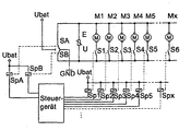
- Fig. 1 the structure is schematic in a block diagram an actuator control shown, in which the actuators Motors M1, ..., Mx are. These motors M1, ..., Mx are over first relay 1 - X, consisting of the respective associated Relay coils Sp1 to Spx and those serving as switching means Relay contacts S1 to Sx, to which on lines 1 and 2 connected potentials switched.
- first relay 1 - X consisting of the respective associated Relay coils Sp1 to Spx and those serving as switching means Relay contacts S1 to Sx, to which on lines 1 and 2 connected potentials switched.
- a second relay A consisting of the relay coil SpA and the associated one Relay contact SA, a line 7 with two different Potentials, in the example shown either with GND or Ubat, connected. This different potential lies accordingly on one side of motors M1, ..., Mx.
- a line 6 with two different potentials in the example shown either with GND or Ubat. Accordingly, this is different potential on the second side of the motors M1, ..., Mx on. In this way, the clockwise or counterclockwise rotation of the Motors are determined.
- the control of the relay coils Sp1 to Spx, SpA and SpB are carried out by a control unit which corresponding switching signals or switching commands to the as Switching relay contacts in the corresponding Spend switch positions.
- the action of the relay coils on the associated relay contacts is by dotted lines indicated.
- Control device preferably provided a microcontroller and an in Device not shown in the figure for Total current measurement of all actuators, for example via one Shunt resistance in the line between the relay contacts SA / SB, line 5 and the GND potential, or a current measurement each path separately or a mixture of the two.
- the first test step involves driving the relay coil SpA and thus the closing of the relay contact SA after line 8.
- the potential Ubat on the motors is then on line 7 M1, ..., Mx on.
- the microcontroller measures a current, the greater than zero, generally: greater than an expected Setpoint, is and thus detects that one of the relays 1 to x, consisting of relay coils Sp1 to Spx and associated Relay contacts S1 to Sx, 'hangs in the closed position) Line 2).
- the control of the control unit for test purposes Relay takes place so long that the relays pull securely. On the other hand, the control is not maintained for so long received so that a malfunction of the relay Keep actuator movement as minimal as possible. In the The data of the used relays.
- the potential Ubat is then on line 6 on motors M1, ..., Mx.
- the microcontroller measures one Current greater than zero, generally: greater than an expected Setpoint, is and thus detects that one of the relays 1 to x, consisting of relay coils Sp1 to Spx and associated Relay contacts S1 to Sx, 'hangs in the closed position (against Line 2).
- a second test step is now that any Relay 1 to x, consisting of the associated relay coils Sp1 to Spx and the relay contacts S1 to Sx. Is now one of the relays A or B, consisting of a relay coil SpA / SpB and associated relay contact SA / SB, faulty closed, then the microcontroller measures a current that is larger is as zero. This detects that one of the relays A and B 'hangs' in position against the Ubat potential on line 8. After This second test step reverses the arrangement after the Control back to the basic position described above.
- the test regarding the 'hanging' of relays 1 - X in open Position or relays A and B against GND potential is via a minimum current detection in normal operation of the system, with the actuator control of the microcontroller does not measure any current. The error is then detected.
- test according to the method according to the invention can be carried out arbitrarily, for example after switching on the ignition in a motor vehicle or cyclically or in another appropriately.
- the result is available for diagnostic purposes Available and can in the functionality of the control unit be involved. For example, to ensure that the Detection of a relay malfunction no activation of the corresponding actuator more takes place.
- the method according to the invention can then advantageously also be used when using a semiconductor switch in place of at least one of the relays.
- Semiconductor switches can for example be a MOSFET transistor Find use.
- the method according to the invention enables a relay test without Movement of the actuators, provided the relays are OK. It also saves a lot of time because it doesn't all relays must be controlled for the test.
Description
Die Erfindung geht aus von einem Verfahren zur Erkennung von Fehlschaltungen eines ersten Relais, dessen Schaltmittel in Reihe mit einem Verbraucher geschaltet ist, der im Oberbegriff des Anspruchs 1 definierten Gattung.The invention is based on a method for the detection of Incorrect switching of a first relay, its switching means in series is connected to a consumer that is in the preamble of Claim 1 defined genus.
Aus der DE 31 35 888 C2 ist ein Verfahren bekannt, welches zur Erkennung von Fehlschaltungen von Relais dient, dessen Schaltmittel in Reihe mit einem Verbraucher geschaltet ist und je nach Schaltstellung nach Maßgabe von Schaltbefehlen die Verbindung zum Verbraucher unterbricht oder schließt. Wird eine Fehlschaltung erkannt, entweder bei den Schaltbefehlen oder bei den Relais, wird der motorische Verbraucher so mit Potential versorgt, daß er am Anlaufen gehindert ist. Vorliegende Fehlererkennung beruht auf der Erkennung bestimmter Potentiale und deren recht komplexen Auswertung. From DE 31 35 888 C2 a method is known which for Detection of faulty switching of relays is used Switching means is connected in series with a consumer and each the connection according to the switching position in accordance with switching commands to the consumer interrupts or closes. Will a malfunction recognized, either with the switching commands or with the relays the motor consumer is supplied with potential so that it Start is prevented. The existing fault detection is based on the Detection of certain potentials and their quite complex ones Evaluation.
Das erfindungsgemäße Verfahren zur Erkennung von Fehlschaltungen eines ersten Relais mit den kennzeichnenden Merkmalen des Anspruchs 1 hat demgegenüber den Vorteil, eine einfache und zuverlässige Lösung zur Verfügung zu stellen, bei welcher ein Relaistest mit Hilfe einer in einem elektronischen Steuergerät implementierten Strommessung durchgeführt wird. In vorteilhafter Weise können somit alle Relais angesteuert werden, ohne daß einer der als Verbraucher vorgesehenen Aktuatoren bewegt werden muß.The method according to the invention for the detection of faulty switching a first relay with the characteristic features of Claim 1 has the advantage of a simple and to provide a reliable solution where one Relay test using an electronic control unit implemented current measurement is carried out. In advantageous All relays can thus be controlled without one the actuators provided as consumers must be moved.
Bei dem Verfahren nach der Erfindung wird dazu prinzipiell ein durch einen die Schaltmittel beinhaltenden Stromkreis fließender Strom erfaßt und eine Fehlfunktion des Relais, insbesondere ein Kleben des Schaltmittels, erkannt, wenn die Stromstärke nicht der gemäß der angewählten Schaltstellung zu erwartenden Stromstärke entspricht.In principle, in the method according to the invention, a flowing through a circuit containing the switching means Current is detected and a malfunction of the relay, especially one Sticking of the switching means, recognized if the amperage is not the current strength to be expected according to the selected switching position equivalent.
Durch die in den weiteren Ansprüchen niedergelegten Maßnahmen sind vorteilhafte Weiterbildungen und Verbesserungen des im Anspruch 1 angegebenen Verfahrens möglich.Through the measures laid down in the further claims are advantageous further developments and improvements in Claim 1 specified method possible.
Nach einer besonders zweckmäßigen Weiterbildung der Erfindung ist wenigstens ein zweites Relais vorgesehen, das eine erste Klemme des Stromkreises durch Umschaltung auf wenigstens zwei verschiedene Potentiale legen kann, und eine zweite Klemme des Stromkreises auf einem ersten der beiden Potentiale liegt, vorgesehen, und erfindungsgemäß wird an das zweite Relais ein Schaltsignal zur Verbindung der ersten Klemme mit dem zweiten Potential abgegeben und an das erste Relais wird ein Schaltsignal zum Öffnen gegeben, und ein einen Fehler der beiden Relais kennzeichnendes erstes Fehlersignal wird dann abgegeben, wenn ein Stromfluß in dem Stromkreis erkannt wird. According to a particularly expedient development of the invention at least one second relay is provided which has a first terminal the circuit by switching to at least two can put different potentials, and a second terminal of the Circuit lies on a first of the two potentials, provided, and according to the invention is a to the second relay Switching signal for connecting the first terminal to the second Potential is given and a switching signal is sent to the first relay given to open, and a failure of the two relays characteristic first error signal is emitted when a Current flow in the circuit is detected.
In vorteilhafter Ausgestaltung dieser erfindungsgemäßen Weiterbildung ist vorgesehen, daß an das zweite Relais ein Schaltsignal zur Schaltung der ersten Klemme an das erste Potential gegeben wird und an das erste Relais ein Schaltsignal zum Schließen gegeben wird, wenn im vorhergehenden Schritt kein Fehler erkannt wurde, und daß ein einen Fehler der beiden Relais kennzeichnendes Fehlersignal abgegeben wird, wenn ein Stromfluß im Stromkreis erkannt wird.In an advantageous embodiment of this invention Training is provided that a to the second relay Switching signal for switching the first terminal to the first Potential is given and a switching signal to the first relay is given to close if none in the previous step Fault was detected, and that a fault of the two relays characteristic error signal is emitted when a current flow in the Circuit is recognized.
In einer weiteren vorteilhaften Ausgestaltung der Erfindung ist vorgesehen, daß mehrere Verbraucher mit zugeordneten ersten Relais parallel zu den beiden Klemmen geschaltet sind und Fehler in einzelnen und/oder mehreren der Relais erkannt werden.In a further advantageous embodiment of the invention provided that several consumers with assigned first relays are connected in parallel to the two terminals and errors in individual and / or more of the relays are recognized.
In besonders vorteilhafter und zweckmäßiger Weiterbildung der Erfindung ist ein drittes Relais vorgesehen, über das die zweite Klemme mit einem der beiden Potentiale verbunden werden kann. Entsprechend einer vorteilhaften Anwendung dieser erfindungsgemäßen Weiterbildung wird durch Schalten des dritten Relais eine Fehlfunktion des zweiten Relais und umgekehrt festgestellt.In a particularly advantageous and expedient development of Invention, a third relay is provided, via which the second Terminal can be connected to one of the two potentials. According to an advantageous application of this Training according to the invention is achieved by switching the third Relay malfunction of the second relay and vice versa detected.
Eine weitere vorteilhaften Ausgestaltung der Erfindung ist gekennzeichnet durch die Verwendung eines Halbleiterschalters an Stelle wenigstens eines der Relais.Another advantageous embodiment of the invention is characterized by the use of a semiconductor switch Place at least one of the relays.
Die Erfindung ist anhand eines in der Zeichnung dargestellten Ausführungsbeispiels in der nachfolgenden Beschreibung näher erläutert. Die einzige Figur zeigt schematisch ein Blockschaltbild einer Aktuatoransteuerung, dargestellt anhand von Motoren, bei der das erfindungsgemäße Verfahren vorteilhaft einsetzbar ist.The invention is based on one shown in the drawing Exemplary embodiment in the following description explained. The single figure shows schematically a block diagram an actuator control, shown using motors, in the the method according to the invention can be used advantageously.
In Fig. 1 ist schematisch in einem Blockschaltbild der Aufbau einer Aktuatoränsteuerung dargestellt, bei dem die Aktuatoren Motore M1, ..., Mx sind. Diese Motore M1, ..., Mx werden über erste Relais 1 - X, bestehend aus den jeweils zugehörigen Relaisspulen Sp1 bis Spx und den als Schaltmittel dienenden Relaiskontakten S1 bis Sx, an die an den Leitungen 1 bzw. 2 anliegenden Potentiale geschaltet. Mit Hilfe eines zweiten Relais A, bestehend aus der Relaisspule SpA und dem zugehörigen Relaiskontakt SA, wird eine Leitung 7 mit zwei verschiedenen Potentialen, im dargestellten Beispiel entweder mit GND oder Ubat, verbunden. Dementsprechend liegt dieses unterschiedliche Potential an der einen Seite der Motoren M1, ..., Mx an. Mit Hilfe eines weiteren Relais B, bestehend aus der Relaisspule SpB und dem zugehörigen Relaiskontakt SB, wird eine Leitung 6 mit zwei verschiedenen Potentialen, im dargestellten Beispiel entweder mit GND oder Ubat, verbunden. Dementsprechend liegt dieses unterschiedliche Potential an der zweiten Seite der Motoren M1, ..., Mx an. Auf diese Weise kann der Rechts- oder Linkslauf der Motoren bestimmt werden. Die Ansteuerung der Relaisspulen Sp1 bis Spx, SpA und SpB erfolgt von einem Steuergerät aus, welches die entsprechenden Schaltsignale bzw. Schaltbefehle abgibt, um die als Schaltmittel dienenden Relaiskontakte in die entsprechenden Schaltstellungen zu verbringen. Die Einwirkung der Relaisspulen auf die zugehörigen Relaiskontakte ist durch gepunktete Linien angedeutet.In Fig. 1, the structure is schematic in a block diagram an actuator control shown, in which the actuators Motors M1, ..., Mx are. These motors M1, ..., Mx are over first relay 1 - X, consisting of the respective associated Relay coils Sp1 to Spx and those serving as switching means Relay contacts S1 to Sx, to which on lines 1 and 2 connected potentials switched. With the help of a second relay A, consisting of the relay coil SpA and the associated one Relay contact SA, a line 7 with two different Potentials, in the example shown either with GND or Ubat, connected. This different potential lies accordingly on one side of motors M1, ..., Mx. With help of a further relay B, consisting of the relay coil SpB and the associated relay contact SB, a line 6 with two different potentials, in the example shown either with GND or Ubat. Accordingly, this is different potential on the second side of the motors M1, ..., Mx on. In this way, the clockwise or counterclockwise rotation of the Motors are determined. The control of the relay coils Sp1 to Spx, SpA and SpB are carried out by a control unit which corresponding switching signals or switching commands to the as Switching relay contacts in the corresponding Spend switch positions. The action of the relay coils on the associated relay contacts is by dotted lines indicated.
Zur Durchführung des erfindungsgemäßen Verfahrens ist im Steuergerät bevorzugt ein Mikrokontroller vorgesehen sowie eine in der Figur nicht näher dargestellte Vorrichtung zur Summenstrommessung aller Aktuatoren, beispielsweise über einen Shunt-Widerstand in der Leitung zwischen den Relaiskontakten SA/SB, Leitung 5 und dem GND-Potential, oder einer Strommessung jedes Pfades getrennt oder einer Mischung aus beidem.To carry out the method according to the invention Control device preferably provided a microcontroller and an in Device not shown in the figure for Total current measurement of all actuators, for example via one Shunt resistance in the line between the relay contacts SA / SB, line 5 and the GND potential, or a current measurement each path separately or a mixture of the two.
Zur Überprüfung der in der Figur dargestellten Relais, ob diese beispielsweise in geschlossenem Zustand 'Kleben', genügen die nachfolgend aufgeführten Testschritte. Dabei ist von folgender, in der Figur dargestellter Grundstellung der Relaiskontakte ausgegangen: die Relaiskontakte S1 bis Sx sind offen, die Relaiskontakte SA und SB liegen auf GND-Potential.To check the relay shown in the figure, whether this for example, in the closed state 'glue', are sufficient test steps listed below. It is from the following, in the figure shown basic position of the relay contacts out: the relay contacts S1 to Sx are open, the Relay contacts SA and SB are at GND potential.
Der erste Testschritt beinhaltet das Ansteuern der Relaisspule SpA und damit das Schließen des Relaiskontaktes SA nach Leitung 8. Damit liegt dann auf Leitung 7 das Potential Ubat an den Motoren M1, ..., Mx an. Ist nun eines der Relaiskontakte S1 bis Sx fehlerhaft geschlossen, dann mißt der Mikrokontroller einen Strom, der größer als Null, allgemein: größer als ein erwarteter Sollwert, ist und detektiert damit, daß eines der Relais 1 bis x, bestehend aus Relaisspulen Sp1 bis Spx sowie zugehörigen Relaiskontakten S1 bis Sx, 'hängt in geschlossener Position )gegen Leitung 2). Mißt das Steuergerät bzw. der Mikrokontroller keinen derartigen Strom, dann sind alle den Motoren zugeordnete erste Relais 1 - x offen oder das Relais A, bestehend aus Relaisspule SpA sowie zugehörigem Relaiskontakt SA, 'hängt' gegen Leitung 5. Nach diesem ersten Testschritt kehrt die Anordnung nach Beendigung der Ansteuerung in die vorstehend beschriebene Grundstellung zurück.The first test step involves driving the relay coil SpA and thus the closing of the relay contact SA after line 8. The potential Ubat on the motors is then on line 7 M1, ..., Mx on. Is now one of the relay contacts S1 to Sx closed incorrectly, then the microcontroller measures a current, the greater than zero, generally: greater than an expected Setpoint, is and thus detects that one of the relays 1 to x, consisting of relay coils Sp1 to Spx and associated Relay contacts S1 to Sx, 'hangs in the closed position) Line 2). Does not measure the control unit or the microcontroller such current, then all are first associated with the motors Relay 1 - x open or relay A, consisting of a relay coil SpA and associated relay contact SA, 'hangs' against line 5. After this first test step, the arrangement returns after completion the control in the basic position described above back.
Die vom Steuergerät für Testzwecke vorgenommene Ansteuerung der Relais erfolgt solange, daß die Relais sicher anziehen. Andererseits wird die Ansteuerung nicht so lange aufrecht erhalten, um somit bei einer Fehlfunktion der Relais eine Aktuatorbewegung so minimal wie irgend möglich zu halten. Bei der Wahl der erforderlichen Ansteuerzeit werden die Daten der verwendeten Relais beachtet.The control of the control unit for test purposes Relay takes place so long that the relays pull securely. On the other hand, the control is not maintained for so long received so that a malfunction of the relay Keep actuator movement as minimal as possible. In the The data of the used relays.
In einem optionalen Testschritt erfolgt das Ansteuern der Relaisspule SpB und damit das Schließen des Relaiskontaktes SB nach Leitung 8. Damit liegt dann auf Leitung 6 das Potential Ubat an den Motoren M1, ..., Mx an. Ist nun eines der Relaiskontakte S1 bis Sx fehlerhaft geschlossen, dann mißt der Mikrokontroller einen Strom, der größer als Null, allgemein: größer als ein erwarteter Sollwert, ist und detektiert damit, daß eines der Relais 1 bis x, bestehend aus Relaisspulen Sp1 bis Spx sowie zugehörigen Relaiskontakten S1 bis Sx, 'hängt in geschlossener Position (gegen Leitung 2). Mißt das Steuergerät bzw. der Mikrokontroller keinen derartigen Strom, dann sind alle den Motoren zugeordnete erste Relais 1 - x offen oder das Relais B, bestehend aus Relaisspule SpB sowie zugehörigem Relaiskontakt SB, 'hängt' gegen Leitung 5. Nach diesem optionalen Testschritt kehrt die Anordnung nach Beendigung der Ansteuerung in die vorstehend beschriebene Grundstellung zurück.In an optional test step, the Relay coil SpB and thus the closing of the relay contact SB after line 8. The potential Ubat is then on line 6 on motors M1, ..., Mx. Is now one of the relay contacts S1 until Sx is closed incorrectly, then the microcontroller measures one Current greater than zero, generally: greater than an expected Setpoint, is and thus detects that one of the relays 1 to x, consisting of relay coils Sp1 to Spx and associated Relay contacts S1 to Sx, 'hangs in the closed position (against Line 2). Does not measure the control unit or the microcontroller such current, then all are first associated with the motors Relay 1 - x open or relay B, consisting of a relay coil SpB and associated relay contact SB, 'hangs' against line 5. After this optional test step, the arrangement is repeated Completion of the control in the above Home position back.
Mit diesem ersten bzw. optionalen Testschritt werden alle Relais überprüft. Wird kein Strom gemessen und damit Fehlverhalten festgestellt, kann auf weitere Tests verzichtet werden.With this first or optional test step, all relays checked. If no current is measured and misconduct occurs determined, further tests can be dispensed with.
Ein zweiter Testschritt besteht nun darin, daß ein beliebiges Relais 1 bis x, bestehend aus den jeweils zugehörigen Relaisspulen Sp1 bis Spx und den Relaiskontakten S1 bis Sx, angesteuert wird. Ist nun eines der Relais A oder B, bestehend aus Relaisspule SpA/SpB sowie zugehörigem Relaiskontakt SA/SB, fehlerhaft geschlossen, dann mißt der Mikrokontroller einen Strom, der größer als Null ist. Damit wird detektiert, daß eines der Relais A bzw. B 'hängt' in Position gegen das Potential Ubat auf Leitung 8. Nach diesem zweiten Testschritt kehrt die Anordnung nach Beendigung der Ansteuerung in die vorstehend beschriebene Grundstellung zurück.A second test step is now that any Relay 1 to x, consisting of the associated relay coils Sp1 to Spx and the relay contacts S1 to Sx. Is now one of the relays A or B, consisting of a relay coil SpA / SpB and associated relay contact SA / SB, faulty closed, then the microcontroller measures a current that is larger is as zero. This detects that one of the relays A and B 'hangs' in position against the Ubat potential on line 8. After This second test step reverses the arrangement after the Control back to the basic position described above.
Der Test bezüglich des 'Hängens' der Relais 1 - X in offener Position bzw. der Relais A und B gegen GND-Potential erfolgt über eine Mindeststromerkennung im Normalbetrieb des Systems, wobei bei der Aktuatoransteuerung der Mikrokontroller keinen Strom mißt. Daraufhin erfolgt die Fehlerdetektion.The test regarding the 'hanging' of relays 1 - X in open Position or relays A and B against GND potential is via a minimum current detection in normal operation of the system, with the actuator control of the microcontroller does not measure any current. The error is then detected.
Der Test entsprechend dem erfindungsgemäßen Verfahren kann beliebig durchgeführt werden, beispielsweise nach dem Einschalten der Zündung bei einem Kraftfahrzeug oder zyklisch oder in anderer geeigneter Weise. Das Ergebnis steht für Diagnosezwecke zur Verfügung und kann in die Funktionalität des Steuergerätes eingebunden werden. So kann z.B. dafür gesorgt werden, daß bei der Feststellung einer Relaisfehlfunktion keine Ansteuerung des entsprechenden Aktuators mehr erfolgt.The test according to the method according to the invention can can be carried out arbitrarily, for example after switching on the ignition in a motor vehicle or cyclically or in another appropriately. The result is available for diagnostic purposes Available and can in the functionality of the control unit be involved. For example, to ensure that the Detection of a relay malfunction no activation of the corresponding actuator more takes place.
Das erfindungsgemäße Verfahren kann vorteilhafterweise auch dann eingesetzt werden, wenn die Verwendung eines Halbleiterschalters an Stelle wenigstens eines der Relais vorgesehen ist. Als Halbleiterschalter kann beispielsweise ein MOSFET-Transistor Verwendung finden.The method according to the invention can then advantageously also be used when using a semiconductor switch in place of at least one of the relays. As Semiconductor switches can for example be a MOSFET transistor Find use.
Das erfindungsgemäße Verfahren ermöglicht einen Relaistest ohne Bewegung der Aktuatoren, vorausgesetzt die Relais sind in Ordnung. Es bringt darüber hinaus eine wesentliche Zeitersparnis, da nicht alle Relais zum Test angesteuert werden müssen.The method according to the invention enables a relay test without Movement of the actuators, provided the relays are OK. It also saves a lot of time because it doesn't all relays must be controlled for the test.
Claims (6)
- Method for detecting malfunctions of a first relay, operated on d.c. voltage, the switching means of which is connected in series to a load and, depending on the switching position, interrupts or closes the connection to the load in accordance with switching commands, characterized in that a current flowing through a circuit containing the switching means is sensed and a malfunction of the first relay, in particular a sticking of the switching means, is detected if the current intensity does not correspond to the current intensity to be expected according to the chosen switching position, furthermore at least a second relay, likewise operated on d.c. voltage, is provided and can apply at least two different potentials to a first terminal of the circuit by means of switching over, and a second terminal of the circuit lies at a first of the two potentials, and in that a switching signal for connecting the first terminal to the second potential is emitted to the second relay and a switching signal for opening is passed to the first relay, and in that a first malfunction signal, identifying a malfunction of the two relays, is emitted if a current flow in the circuit is detected.
- Method according to Claim 1, characterized in that a switching signal for switching the first terminal to the first potential is passed to the second relay and a switching signal for closing is passed to the first relay if no malfunction was detected in the previous step, and in that a malfunction signal identifying a malfunction of the two relays is emitted if a current flow in the circuit is detected.
- Method according to Claim 1 or 2, characterized in that a plurality of loads are connected with the assigned first relay in parallel with the two terminals and malfunctions in one and/or more of the relays are detected.
- Method according to one of Claims 1 to 3, characterized in that a third relay is provided, via which the second terminal can be connected to one of the two potentials.
- Method according to Claim 4, characterized in that, by switching the third relay, a malfunction of the second relay is established, and vice versa.
- Method according to one of the preceding claims, characterized by the use of a semiconductor switch in place of at least one of the relays.
Applications Claiming Priority (5)
| Application Number | Priority Date | Filing Date | Title |
|---|---|---|---|
| DE19736731 | 1997-08-22 | ||
| DE19736731 | 1997-08-22 | ||
| DE19805658 | 1998-02-12 | ||
| DE19805658A DE19805658A1 (en) | 1997-08-22 | 1998-02-12 | Method for detecting faulty switching of a first relay |
| PCT/DE1998/002410 WO1999010780A1 (en) | 1997-08-22 | 1998-08-19 | Method for detecting malfunctions of a first relay |
Publications (2)
| Publication Number | Publication Date |
|---|---|
| EP1004059A1 EP1004059A1 (en) | 2000-05-31 |
| EP1004059B1 true EP1004059B1 (en) | 2002-08-14 |
Family
ID=26039408
Family Applications (1)
| Application Number | Title | Priority Date | Filing Date |
|---|---|---|---|
| EP98951166A Expired - Lifetime EP1004059B1 (en) | 1997-08-22 | 1998-08-19 | Method for detecting malfunctions of a first relay |
Country Status (5)
| Country | Link |
|---|---|
| US (1) | US6304189B1 (en) |
| EP (1) | EP1004059B1 (en) |
| BR (1) | BR9811960A (en) |
| ES (1) | ES2182364T3 (en) |
| WO (1) | WO1999010780A1 (en) |
Cited By (2)
| Publication number | Priority date | Publication date | Assignee | Title |
|---|---|---|---|---|
| EP2085836A1 (en) | 2008-01-29 | 2009-08-05 | BSH Bosch und Siemens Hausgeräte GmbH | Circuit arrangement and method for operating a home appliance |
| EP2093581A1 (en) * | 2008-02-19 | 2009-08-26 | E.G.O. Control Systems GmbH | Control device for a domestic appliance, domestic appliance and corresponding method |
Families Citing this family (12)
| Publication number | Priority date | Publication date | Assignee | Title |
|---|---|---|---|---|
| US6683778B2 (en) * | 2000-02-18 | 2004-01-27 | Sanyo Electric Co., Ltd. | Device for use in electric vehicles for detecting adhesion in relay due to melting |
| US6696968B2 (en) * | 2001-02-28 | 2004-02-24 | Josette Tari | Visualization luminous device adapted for electric motors of equipments supplied by the three-phase voltage |
| US6882155B2 (en) * | 2001-04-19 | 2005-04-19 | Vince J Lazzaro | Remotely actuated, circuit testing emergency stop apparatus and method |
| US7417519B2 (en) * | 2004-09-30 | 2008-08-26 | Rockwell Automation Technologies, Inc. | Emergency stop relay combination |
| CA2513018A1 (en) * | 2005-07-22 | 2007-01-22 | Research In Motion Limited | Method for training a proxy server for content delivery based on communication of state information from a mobile device browser |
| US7606363B1 (en) | 2005-07-26 | 2009-10-20 | Rockwell Collins, Inc. | System and method for context switching of a cryptographic engine |
| DE102007002060B4 (en) * | 2007-01-13 | 2010-12-02 | Diehl Ako Stiftung & Co. Kg | Apparatus and method for assessing erroneous operation of a cooktop |
| US8441248B2 (en) | 2010-10-21 | 2013-05-14 | Whirlpool Corporation | Laundry treating appliance with voltage detection |
| GB2486493B (en) * | 2010-12-17 | 2016-06-15 | Ge Aviat Systems Ltd | Switching circuits and methods of testing |
| US8836338B2 (en) | 2011-12-16 | 2014-09-16 | Ge Aviation Systems Limited | Switching circuits and methods of testing thereof |
| US9236209B2 (en) * | 2013-04-03 | 2016-01-12 | Tektronix, Inc. | Relay failure detection system |
| WO2017102025A1 (en) * | 2015-12-18 | 2017-06-22 | Pepperl+Fuchs Gmbh | Methods and apparatuses for monitoring the functionality of redundantly interconnected contacts |
Family Cites Families (7)
| Publication number | Priority date | Publication date | Assignee | Title |
|---|---|---|---|---|
| DE3135888A1 (en) | 1981-09-10 | 1983-03-24 | Robert Bosch Gmbh, 7000 Stuttgart | SAFETY DEVICE FOR AN ELECTRICAL ACTUATOR |
| CA1263144A (en) | 1984-06-04 | 1989-11-21 | Heihachiro Umemura | Relay trouble detecting device |
| US5136280A (en) * | 1989-05-15 | 1992-08-04 | Teledyne Industries, Inc. | Switch status indicator and self tester |
| US5243291A (en) * | 1991-10-11 | 1993-09-07 | Shinkoh Electric Co., Ltd. | Electromagnetic contactor deposition detecting apparatus which detects load current and switch current |
| DE4211251C1 (en) | 1992-04-03 | 1993-07-15 | Siemens Ag, 8000 Muenchen, De | |
| JP2594573Y2 (en) | 1993-11-02 | 1999-04-26 | 住友電装株式会社 | Relay abnormality detection device |
| JPH09213471A (en) | 1996-01-30 | 1997-08-15 | Sanyo Electric Co Ltd | Microwave oven |
-
1998
- 1998-08-19 ES ES98951166T patent/ES2182364T3/en not_active Expired - Lifetime
- 1998-08-19 BR BR9811960-5A patent/BR9811960A/en not_active IP Right Cessation
- 1998-08-19 EP EP98951166A patent/EP1004059B1/en not_active Expired - Lifetime
- 1998-08-19 US US09/486,169 patent/US6304189B1/en not_active Expired - Lifetime
- 1998-08-19 WO PCT/DE1998/002410 patent/WO1999010780A1/en active IP Right Grant
Cited By (2)
| Publication number | Priority date | Publication date | Assignee | Title |
|---|---|---|---|---|
| EP2085836A1 (en) | 2008-01-29 | 2009-08-05 | BSH Bosch und Siemens Hausgeräte GmbH | Circuit arrangement and method for operating a home appliance |
| EP2093581A1 (en) * | 2008-02-19 | 2009-08-26 | E.G.O. Control Systems GmbH | Control device for a domestic appliance, domestic appliance and corresponding method |
Also Published As
| Publication number | Publication date |
|---|---|
| WO1999010780A1 (en) | 1999-03-04 |
| US6304189B1 (en) | 2001-10-16 |
| ES2182364T3 (en) | 2003-03-01 |
| EP1004059A1 (en) | 2000-05-31 |
| BR9811960A (en) | 2000-08-15 |
Similar Documents
| Publication | Publication Date | Title |
|---|---|---|
| EP1004059B1 (en) | Method for detecting malfunctions of a first relay | |
| DE3341472C2 (en) | Circuit arrangement with a microcomputer | |
| EP1490700B1 (en) | Circuit arrangement and method for testing an electric circuit | |
| EP2357484B1 (en) | Method for diagnosing an electrical connection and output assembly | |
| WO2009124884A1 (en) | Apparatus and method for recognizing an error in a power bridge circuit | |
| DE19611522B4 (en) | Method and device for fault detection in an output stage circuit arrangement | |
| EP1594021B1 (en) | Circuit device and method for testing relay switching contacts of a digital output circuit | |
| EP1032519B1 (en) | Protective circuit for a controlling element and method for testing the control circuit of a controlling element | |
| DE102010000852A1 (en) | Method of operating a brushless motor | |
| DE19805658A1 (en) | Method for detecting faulty switching of a first relay | |
| DE102005028058B3 (en) | Drive for a swing panel, e.g. a door, has a control system which gives a cyclic test of the motor and brake circuits and generates a safety reaction on detection of a fault | |
| DE19906932B4 (en) | Binary | |
| DE4313532B4 (en) | Method for checking an output stage | |
| DE102018218800B4 (en) | Actuator device, valve device and method for detecting a position of an actuator | |
| EP2876509B1 (en) | Safety control | |
| WO2018059649A1 (en) | Relay circuit | |
| DE102018215687B4 (en) | Actuator device, valve device and method for detecting a position of an actuator | |
| DE10246107B4 (en) | Method and circuit arrangement for fault monitoring of at least one electrical load | |
| DE102016203504A1 (en) | Method for operating an electric motor | |
| DE102008018642A1 (en) | Monitoring circuit and method for testing the circuit | |
| EP1872476B1 (en) | Method and device for recognising a load which is connected to a relay | |
| DE10359235B3 (en) | Testing power end stages involves switching semiconductor switches sequentially or simultaneously into conducting state, checking voltage at star point of motor windings against tolerance range to detecting end stage fault | |
| EP1215811B1 (en) | Method and device for monitoring stepper motors | |
| EP2750960B1 (en) | Electrical motor having a test current source | |
| DE102012224181A1 (en) | Electrical circuit for fuel heater of filter device used in vehicle, has measurement circuit that is arranged between control current circuit and load current circuit to measure measurement signal in control current circuit |
Legal Events
| Date | Code | Title | Description |
|---|---|---|---|
| PUAI | Public reference made under article 153(3) epc to a published international application that has entered the european phase |
Free format text: ORIGINAL CODE: 0009012 |
|
| 17P | Request for examination filed |
Effective date: 20000322 |
|
| AK | Designated contracting states |
Kind code of ref document: A1 Designated state(s): DE ES FR GB IT |
|
| GRAG | Despatch of communication of intention to grant |
Free format text: ORIGINAL CODE: EPIDOS AGRA |
|
| 17Q | First examination report despatched |
Effective date: 20011119 |
|
| GRAG | Despatch of communication of intention to grant |
Free format text: ORIGINAL CODE: EPIDOS AGRA |
|
| GRAH | Despatch of communication of intention to grant a patent |
Free format text: ORIGINAL CODE: EPIDOS IGRA |
|
| GRAH | Despatch of communication of intention to grant a patent |
Free format text: ORIGINAL CODE: EPIDOS IGRA |
|
| GRAA | (expected) grant |
Free format text: ORIGINAL CODE: 0009210 |
|
| AK | Designated contracting states |
Kind code of ref document: B1 Designated state(s): DE ES FR GB IT |
|
| PG25 | Lapsed in a contracting state [announced via postgrant information from national office to epo] |
Ref country code: GB Free format text: LAPSE BECAUSE OF FAILURE TO SUBMIT A TRANSLATION OF THE DESCRIPTION OR TO PAY THE FEE WITHIN THE PRESCRIBED TIME-LIMIT Effective date: 20020814 |
|
| REG | Reference to a national code |
Ref country code: GB Ref legal event code: FG4D Free format text: NOT ENGLISH |
|
| REF | Corresponds to: |
Ref document number: 59805201 Country of ref document: DE Date of ref document: 20020919 |
|
| PGFP | Annual fee paid to national office [announced via postgrant information from national office to epo] |
Ref country code: GB Payment date: 20020926 Year of fee payment: 5 |
|
| GBV | Gb: ep patent (uk) treated as always having been void in accordance with gb section 77(7)/1977 [no translation filed] |
Effective date: 20020814 |
|
| ET | Fr: translation filed | ||
| REG | Reference to a national code |
Ref country code: ES Ref legal event code: FG2A Ref document number: 2182364 Country of ref document: ES Kind code of ref document: T3 |
|
| PLBE | No opposition filed within time limit |
Free format text: ORIGINAL CODE: 0009261 |
|
| STAA | Information on the status of an ep patent application or granted ep patent |
Free format text: STATUS: NO OPPOSITION FILED WITHIN TIME LIMIT |
|
| 26N | No opposition filed |
Effective date: 20030515 |
|
| PGFP | Annual fee paid to national office [announced via postgrant information from national office to epo] |
Ref country code: FR Payment date: 20090819 Year of fee payment: 12 Ref country code: ES Payment date: 20090821 Year of fee payment: 12 |
|
| PGFP | Annual fee paid to national office [announced via postgrant information from national office to epo] |
Ref country code: IT Payment date: 20090826 Year of fee payment: 12 |
|
| REG | Reference to a national code |
Ref country code: FR Ref legal event code: ST Effective date: 20110502 |
|
| PG25 | Lapsed in a contracting state [announced via postgrant information from national office to epo] |
Ref country code: IT Free format text: LAPSE BECAUSE OF NON-PAYMENT OF DUE FEES Effective date: 20100819 |
|
| PG25 | Lapsed in a contracting state [announced via postgrant information from national office to epo] |
Ref country code: FR Free format text: LAPSE BECAUSE OF NON-PAYMENT OF DUE FEES Effective date: 20100831 |
|
| REG | Reference to a national code |
Ref country code: ES Ref legal event code: FD2A Effective date: 20111019 |
|
| PG25 | Lapsed in a contracting state [announced via postgrant information from national office to epo] |
Ref country code: ES Free format text: LAPSE BECAUSE OF NON-PAYMENT OF DUE FEES Effective date: 20100820 |
|
| PGFP | Annual fee paid to national office [announced via postgrant information from national office to epo] |
Ref country code: DE Payment date: 20121024 Year of fee payment: 15 |
|
| PG25 | Lapsed in a contracting state [announced via postgrant information from national office to epo] |
Ref country code: DE Free format text: LAPSE BECAUSE OF NON-PAYMENT OF DUE FEES Effective date: 20140301 |
|
| REG | Reference to a national code |
Ref country code: DE Ref legal event code: R119 Ref document number: 59805201 Country of ref document: DE Effective date: 20140301 |