EP1004013B1 - Automated biological reaction system - Google Patents
Automated biological reaction system Download PDFInfo
- Publication number
- EP1004013B1 EP1004013B1 EP98939901.9A EP98939901A EP1004013B1 EP 1004013 B1 EP1004013 B1 EP 1004013B1 EP 98939901 A EP98939901 A EP 98939901A EP 1004013 B1 EP1004013 B1 EP 1004013B1
- Authority
- EP
- European Patent Office
- Prior art keywords
- fluid dispenser
- fluid
- chamber
- reservoir chamber
- piston
- Prior art date
- Legal status (The legal status is an assumption and is not a legal conclusion. Google has not performed a legal analysis and makes no representation as to the accuracy of the status listed.)
- Expired - Lifetime
Links
Images








Classifications
-
- G—PHYSICS
- G01—MEASURING; TESTING
- G01N—INVESTIGATING OR ANALYSING MATERIALS BY DETERMINING THEIR CHEMICAL OR PHYSICAL PROPERTIES
- G01N35/00—Automatic analysis not limited to methods or materials provided for in any single one of groups G01N1/00 - G01N33/00; Handling materials therefor
- G01N35/10—Devices for transferring samples or any liquids to, in, or from, the analysis apparatus, e.g. suction devices, injection devices
- G01N35/1009—Characterised by arrangements for controlling the aspiration or dispense of liquids
- G01N35/1016—Control of the volume dispensed or introduced
-
- G—PHYSICS
- G01—MEASURING; TESTING
- G01N—INVESTIGATING OR ANALYSING MATERIALS BY DETERMINING THEIR CHEMICAL OR PHYSICAL PROPERTIES
- G01N1/00—Sampling; Preparing specimens for investigation
- G01N1/28—Preparing specimens for investigation including physical details of (bio-)chemical methods covered elsewhere, e.g. G01N33/50, C12Q
- G01N1/30—Staining; Impregnating ; Fixation; Dehydration; Multistep processes for preparing samples of tissue, cell or nucleic acid material and the like for analysis
- G01N1/31—Apparatus therefor
- G01N1/312—Apparatus therefor for samples mounted on planar substrates
-
- G—PHYSICS
- G01—MEASURING; TESTING
- G01N—INVESTIGATING OR ANALYSING MATERIALS BY DETERMINING THEIR CHEMICAL OR PHYSICAL PROPERTIES
- G01N35/00—Automatic analysis not limited to methods or materials provided for in any single one of groups G01N1/00 - G01N33/00; Handling materials therefor
- G01N35/00584—Control arrangements for automatic analysers
- G01N35/00722—Communications; Identification
- G01N35/00871—Communications between instruments or with remote terminals
-
- G—PHYSICS
- G01—MEASURING; TESTING
- G01N—INVESTIGATING OR ANALYSING MATERIALS BY DETERMINING THEIR CHEMICAL OR PHYSICAL PROPERTIES
- G01N35/00—Automatic analysis not limited to methods or materials provided for in any single one of groups G01N1/00 - G01N33/00; Handling materials therefor
- G01N35/10—Devices for transferring samples or any liquids to, in, or from, the analysis apparatus, e.g. suction devices, injection devices
- G01N35/1002—Reagent dispensers
-
- G—PHYSICS
- G01—MEASURING; TESTING
- G01N—INVESTIGATING OR ANALYSING MATERIALS BY DETERMINING THEIR CHEMICAL OR PHYSICAL PROPERTIES
- G01N1/00—Sampling; Preparing specimens for investigation
- G01N1/28—Preparing specimens for investigation including physical details of (bio-)chemical methods covered elsewhere, e.g. G01N33/50, C12Q
- G01N1/30—Staining; Impregnating ; Fixation; Dehydration; Multistep processes for preparing samples of tissue, cell or nucleic acid material and the like for analysis
- G01N1/31—Apparatus therefor
- G01N2001/317—Apparatus therefor spraying liquids onto surfaces
-
- G—PHYSICS
- G01—MEASURING; TESTING
- G01N—INVESTIGATING OR ANALYSING MATERIALS BY DETERMINING THEIR CHEMICAL OR PHYSICAL PROPERTIES
- G01N35/00—Automatic analysis not limited to methods or materials provided for in any single one of groups G01N1/00 - G01N33/00; Handling materials therefor
- G01N35/00584—Control arrangements for automatic analysers
- G01N35/00722—Communications; Identification
- G01N35/00871—Communications between instruments or with remote terminals
- G01N2035/00881—Communications between instruments or with remote terminals network configurations
-
- G—PHYSICS
- G01—MEASURING; TESTING
- G01N—INVESTIGATING OR ANALYSING MATERIALS BY DETERMINING THEIR CHEMICAL OR PHYSICAL PROPERTIES
- G01N35/00—Automatic analysis not limited to methods or materials provided for in any single one of groups G01N1/00 - G01N33/00; Handling materials therefor
- G01N35/10—Devices for transferring samples or any liquids to, in, or from, the analysis apparatus, e.g. suction devices, injection devices
- G01N2035/1027—General features of the devices
- G01N2035/1034—Transferring microquantities of liquid
-
- Y—GENERAL TAGGING OF NEW TECHNOLOGICAL DEVELOPMENTS; GENERAL TAGGING OF CROSS-SECTIONAL TECHNOLOGIES SPANNING OVER SEVERAL SECTIONS OF THE IPC; TECHNICAL SUBJECTS COVERED BY FORMER USPC CROSS-REFERENCE ART COLLECTIONS [XRACs] AND DIGESTS
- Y10—TECHNICAL SUBJECTS COVERED BY FORMER USPC
- Y10T—TECHNICAL SUBJECTS COVERED BY FORMER US CLASSIFICATION
- Y10T137/00—Fluid handling
- Y10T137/7722—Line condition change responsive valves
- Y10T137/7837—Direct response valves [i.e., check valve type]
- Y10T137/7869—Biased open
- Y10T137/7871—Weight biased
- Y10T137/7873—Ball valves
-
- Y—GENERAL TAGGING OF NEW TECHNOLOGICAL DEVELOPMENTS; GENERAL TAGGING OF CROSS-SECTIONAL TECHNOLOGIES SPANNING OVER SEVERAL SECTIONS OF THE IPC; TECHNICAL SUBJECTS COVERED BY FORMER USPC CROSS-REFERENCE ART COLLECTIONS [XRACs] AND DIGESTS
- Y10—TECHNICAL SUBJECTS COVERED BY FORMER USPC
- Y10T—TECHNICAL SUBJECTS COVERED BY FORMER US CLASSIFICATION
- Y10T436/00—Chemistry: analytical and immunological testing
- Y10T436/11—Automated chemical analysis
-
- Y—GENERAL TAGGING OF NEW TECHNOLOGICAL DEVELOPMENTS; GENERAL TAGGING OF CROSS-SECTIONAL TECHNOLOGIES SPANNING OVER SEVERAL SECTIONS OF THE IPC; TECHNICAL SUBJECTS COVERED BY FORMER USPC CROSS-REFERENCE ART COLLECTIONS [XRACs] AND DIGESTS
- Y10—TECHNICAL SUBJECTS COVERED BY FORMER USPC
- Y10T—TECHNICAL SUBJECTS COVERED BY FORMER US CLASSIFICATION
- Y10T436/00—Chemistry: analytical and immunological testing
- Y10T436/11—Automated chemical analysis
- Y10T436/112499—Automated chemical analysis with sample on test slide
-
- Y—GENERAL TAGGING OF NEW TECHNOLOGICAL DEVELOPMENTS; GENERAL TAGGING OF CROSS-SECTIONAL TECHNOLOGIES SPANNING OVER SEVERAL SECTIONS OF THE IPC; TECHNICAL SUBJECTS COVERED BY FORMER USPC CROSS-REFERENCE ART COLLECTIONS [XRACs] AND DIGESTS
- Y10—TECHNICAL SUBJECTS COVERED BY FORMER USPC
- Y10T—TECHNICAL SUBJECTS COVERED BY FORMER US CLASSIFICATION
- Y10T436/00—Chemistry: analytical and immunological testing
- Y10T436/25—Chemistry: analytical and immunological testing including sample preparation
- Y10T436/2575—Volumetric liquid transfer
Definitions
- This invention relates to biological reaction systems, and more particularly relates to a method and apparatus for an automated biological reaction system.
- Immunostaining and in situ DNA analysis are useful tools in histological diagnosis and the study of tissue morphology.
- Immunostaining relies on the specific binding affinity of antibodies with epitopes in tissue samples, and the increasing availability of antibodies which bind specifically with unique epitopes present only in certain types of diseased cellular tissue.
- Immunostaining requires a series of treatment steps conducted on a tissue section mounted on a glass slide to highlight by selective staining certain morphological indicators of disease states.
- Typical steps include pretreatment of the tissue section to reduce non-specific binding, antibody treatment and incubation, enzyme labeled secondary antibody treatment and incubation, substrate reaction with the enzyme to produce a fluorophore or chromophore highlighting areas of the tissue section having epitopes binding with the antibody, counterstaining, and the like.
- Each of these steps is separated by multiple rinse steps to remove unreacted residual reagent from the prior step.
- Incubations are conducted at elevated temperatures, usually around 40°C, and the tissue must be continuously protected from dehydration.
- In situ DNA analysis relies upon the specific binding affinity of probes with unique nucleotide sequences in cell or tissue samples and similarly involves a series of process steps, with a variety of reagents and process temperature requirements.
- Automated biological reaction systems include the biological reaction apparatus and the dispensers for the reagents and other fluids used in the biological reaction apparatus.
- the biological reaction apparatus may be computer controlled.
- the computer control is limited in that it is dedicated to and resident on the biological reaction apparatus.
- the memory which is used in conjunction with the computer control, contains data relating to the reagents including serial number, product code (reagent type), package size (250 test), and the like.
- the biological reaction system should apply a predetermined amount of fluid upon the slide in order to consistently test each slide in the automated biological reaction apparatus. Therefore, an important focus of a biological reaction system is to consistently and efficiently apply a predetermined amount of fluid on the slide.
- reagents must be dispensed on the slide in precise amounts using a fluid dispenser.
- the fluid dispenser which is used in conjunction with the biological reaction apparatus, should be easy to manufacture, reliable and compact in size.
- WO96/00195 relates to a medication sprayer used to spray a liquid medication directly from a vial having a needle pierceable septum.
- the sprayer includes a body reciprocally housing the vial.
- a spike assembly includes an air inlet spike connected to the ambient environment and a liquid exit spike, both piercing the septum.
- the liquid exit spike is fluidly coupled to a piston/cylinder arrangement having a combination piston/flapper valve at one end of the cylinder and a supplemental check valve at the other end.
- NL8700226 relates to a method for dosing school paint.
- a pump is screwed onto the bottle of paint in a holder.
- a vacuum in the pump which opens valve in the bottle neck permitting a quantity of school paint into the pump. This is repeated 5 to 25 times to completely fill the pump with school paint, whereby the school paint can be dispensed from the pump through a further valve.
- US5226563 relates to a fluid spraying or dispensing device.
- the device has a sheath extending between an open first end and a second end provided with an end wall which is pierced by at least one hole.
- a fluid tank is slidably mounted inside the sheath and is provided with a fluid ejection device controlled by a push rod secured to the sheath, and a cover is adapted to be slidably engaged on the second end of the sheath.
- the cover includes at least one projection adapted to penetrate through the hole in the end wall of the sheath to enable the push rod to be actuated by pressing against the end wall of the tank.
- US5431309 relates to a liquid soap dispenser having a permanent housing which permits simplified insertion and replacement of disposable fluid reservoirs.
- the housing includes and actuator assembly which is cycled by a lever between first and second positions.
- the actuator assembly is configured to couple to a valve assembly on the reservoir so that when cycled, the valve assembly is actuated in sliding movement to dispense a quantity of fluid.
- the actuator assembly includes a pair of resiliently deformable fingers which act to secure the valve assembly to the actuator assembly for sliding movement therewith. The fingers are deformable to permit movement of the actuator assembly relative to valve assembly.
- a fluid dispenser for use in an automated biological reaction system, the fluid dispenser comprising: a barrel having a reservoir chamber and an upper portion and a lower portion; a coupler having a dispense chamber which is substantially coaxial with the reservoir chamber; a valve is adjacent to the lower portion of the barrel for transferring fluid from the reservoir chamber to the dispense chamber based on pressure differential between the dispense chamber and the reservoir chamber and operative to disallow a flow of fluid from the dispense chamber to the reservoir chamber; and a cap connected to the upper portion of the barrel; characterised in that the barrel is coupled to the coupler with at least a lower portion of the barrel moving downward into the dispense chamber of the coupler, which lower portion of the barrel acts as a piston to expel liquid from the dispense chamber.
- the fluid dispenser may have a vent adjacent to the cap.
- the vent includes a first means to maintain constant pressure in the reservoir chamber, a second means to maintain constant pressure in the reservoir chamber, and a space, the space being between the first and second means to maintain constant pressure in the reservoir chamber.
- the fluid dispenser may have a piston at a lower portion of the barrel, a cap connected to the reservoir chamber, a valve adjacent to the reservoir chamber, and a coupler, wherein the coupler has a dispense chamber whereby the piston moves in the dispense chamber.
- the method includes the step of inserting a valve and a valve insert into the lower portion of a barrel.
- the method also includes the step of welding the cap to the upper portion of the barrel.
- the method further includes the step of placing the ball in the check valve ball seat.
- the method includes the step of snapping the check valve ball seat into the coupler.
- the method includes the step of snapping the coupler and barrel together.
- the method includes the step of providing the fluid dispenser with a cap, a barrel having a reservoir chamber, the barrel being adjacent to the cap, a dispense chamber adjacent to the reservoir chamber, and a nozzle adjacent to the dispense chamber.
- the method also includes the step of providing a syringe with a tip and a syringe plunger.
- the method further includes the step of opening the cap on the fluid dispenser.
- the method also includes the step of filling the reservoir chamber within the fluid dispenser with fluid.
- the method also includes the step of closing the cap on the fluid dispenser.
- the method also includes the step of placing the tip of the syringe inside the nozzle of the fluid dispenser without requiring the fluid dispenser be turned upside down. And, the method also includes the step of expanding the plunger of the syringe in order to draw fluid from the reservoir chamber and the dispense chamber into the syringe.
- an automated biological reaction system has a slide support carousel drive means engaging the slide support carousel for moving the slide support carousel, a consistency pulse application station comprising, at least one nozzle for directing a stream of fluid onto a slide which is less than 35 degrees from the horizontal, and a volume adjust application station positioned above the slide for applying a predetermined amount of fluid on the slide by dropping the fluid onto the slide.
- Also disclosed herein is a method of placing a consistent amount of fluid on a slide in an automated biological reaction apparatus which has at least one rinse station, the rinse station comprising a rinse station nozzle positioned for directing a stream of fluid onto the slide and connected to tubing which is connected to at least one valve.
- the valve is connected to a bottle containing fluid, wherein the valve controls the flow of fluid from the bottle to the nozzle.
- the method includes the step of turning on the valve for supplying fluid to the nozzle and directing a stream of fluid onto the slide.
- the method also includes the step of waiting until the pressure is substantially equal in the tubing.
- the method includes the step of turning off the valve for supplying fluid to the nozzle.
- the method includes the step of providing a rinse station comprising a first rinse station nozzle and a second rinse station nozzle, the first and second rinse station nozzles positioned to direct a stream of fluid onto the slide.
- the method also includes the step of directing a stream of fluid onto the slide from the first rinse station nozzle with a first momentum for a first predetermined amount of time.
- the method includes the step of directing a stream of fluid onto the slide from the second rinse station nozzle for a second predetermined amount of time with a second momentum.
- the method includes the step of directing a stream of fluid onto the slide from the second rinse station nozzle for a third predetermined amount of time with a third momentum, the third momentum being greater than first or second momentum, the third predetermined amount of time being greater than the first or second predetermined amount of time.
- an automated biological reaction apparatus which includes a slide support carousel, drive means engaging the slide support carousel for moving the slide support carousel, a reagent delivery system for applying a predetermined quantity of reagent to one of the slides by movement of the slide support carousel in a reagent delivery zone, a heat zone for heating samples on the slide support carousel, and a rinse station.
- the rinse station comprises a first nozzle, a first valve connected to the first nozzle through tubing, the first valve connected to a bottle containing fluid.
- the rinse station further comprises a controller, the controller controlling the flow of fluid from the bottle to the first nozzle via the operation of the first valve, the controller opening the first valve until the pressure is substantially equal in the tubing.
- an automated biological reaction system which includes a host device, the host device comprising a processor, a memory device connected to the processor, the memory device including a look-up table which contains steps for staining a slide, the processor creating a sequence of steps from the look-up table.
- the automated biological reaction system further includes a remote device, the remote device being physically separate from the host device, the remote device being in electrical communication with the host device.
- the remote device comprises a processor, a memory device connected to the processor.
- a slide support carousel connected to the processor, drive means engaging the slide support carousel for moving the slide support carousel, the drive means connected to the processor, a reagent delivery system for applying a predetermined quantity of reagent to one of the slides by movement of the slide support carousel in a reagent delivery zone, the reagent delivery system connected to the processor, a heat zone for heating samples on the slide support carousel, the heat zone connected to the processor.
- the rinse station connected to the processor, the remote device receiving the sequence of steps from the host device, the remote device executing, through the processor, the sequence of steps in the processor to control the slide support carousel, the reagent delivery system, the heat zone and the rinse station.
- a method for generating a run program in an automated biological reaction system includes the step of providing a host device and a remote device, the remote device being physically separate from the host device. the remote device being in communication with the host device.
- the method also includes the step of reading by the remote device of a barcode on a slide in a carousel on the remote device.
- the method further includes the step of reading by the remote devide of a barcode on a dispenser in the remote device.
- the method includes the step of sending of the slide barcode and dispenser barcode from the remote device to the host device.
- the method includes the step of generating of a sequence of steps for a run based on the slide barcode and dispenser barcode.
- the method includes the step of determining by the host device whether the remote device is capable of executing the sequence of steps.
- the method includes the step of sending by the host device of the sequence of steps to the remote device.
- the memory management system includes a memory device, the memory device including a table containing data for a dispenser used in the automated biological reaction apparatus.
- the memory management system also including a means to transfer the data in the memory device to a host device.
- the host device comprises a processor, a host memory device connected to the processor.
- the host memory device includes a look-up table.
- the processor is connected, via the means to transfer the data in the memory device to a host device, to the memory device, and the processor updates the look-up table in the host memory device based on comparisons to the table in the memory device.
- Also disclosed herein is a method for updating dispenser information in an automated biological reaction system
- the method includes the steps of providing a host device and a memory device, the host device comprising a processor, a host memory device connected to the processor, the host memory device including a look-up table, the memory device including barcode and expiration date information for the dispenser used in the automated biological reaction apparatus.
- the method also includes the step of reading by the host device of the barcode and expiration date information in the memory device.
- the method includes the step of updating the look-up table in the host device based on the barcode and expiration date information in the memory device.
- the method includes the step of writing in the memory device that the barcode and expiration date information has previously been read.
- Also disclosed herein is a method for programming a memory device for an automated biological reaction system
- the method includes the step of selecting a form which includes information on numbers and types of dispensers in a kit for the automated biological reaction system.
- the method also includes the step of scanning in barcodes for a set of dispensers.
- the method includes the step of determining the type of dispenser for each of the dispensers scanned in Further, the method includes the step of comparing whether the numbers types of dispensers scanned in correspond to the numbers and types of dispenser in the kit form.
- the method includes the step of programming the memory device if the numbers types of dispensers scanned in equal the numbers and types of dispenser in the kit form.
- the fluid dispenser for an automated biological reaction system.
- the fluid dispenser has a barrel, the barrel having a reservoir chamber and an upper portion.
- the fluid dispenser also has a cap connected to the upper portion of the barrel.
- the fluid dispenser also has a cup check valve, the cup check valve having a first end and a second end, the cup check valve adjacent to the reservoir chamber at the first end, the cup check valve having a cup piece at the second end.
- the fluid dispenser further has a dispense chamber adjacent to the second end of the cup check valve.
- the valve passes fluid from one side of the valve to the other side based on a pressure differential between the one side and the other side, whereby the valve is placed in a housing.
- the valve includes an attachment, the attachment piece being attached to the housing, a connecting piece being connected to the attachment piece, and a cup piece.
- the cup piece is connected to the connecting piece. The cup piece abuts against the housing when the pressure on the one side of the valve is equal to the pressure on the other side of the valve. The cup piece does not abut against the housing when the pressure on the one side of the valve is unequal to the pressure on the other side of the valve.
- the method includes the step of providing a valve having an attachment piece, a connecting piece being connected to the attachment piece, and a cup piece, the cup piece being connected to the connecting piece.
- the method also including the step of abutting the cup piece against the housing when the pressure on the one side of the valve is equal to the pressure on the other side of the valve.
- the method includes the step of flexing the cup piece inward so that the cup piece is not abutting against the housing when the pressure on the one side of the valve is unequal to the pressure on the other side of the valve.
- the fluid dispenser of the first aspect may have a barrel having a reservoir chamber and a piston, the piston being adjacent to the reservoir chamber, and wherein the fluid dispenser also has an extension piece connected to the piston. And, the fluid dispenser has a coupler, wherein the coupler has a dispense chamber. The dispense chamber is adjacent to the reservoir chamber. Further, the extension piece moves inside the coupler. .
- the fluid dispenser of the first aspect may have a barrel, a piston adjacent to the lower portion of the barrel and a lubricated washer, the lubricated washer coaxial with the piston and a dispense chamber, the dispense chamber adjacent to the barrel.
- a primary object of the invention is to provide an automated biological reaction system which is modular in design.
- Another object of the invention is to provide an automated biological reaction system which consistently and efficiently applies a predetermined amount of buffer upon the slide to which a precise volume of reagent can be added upon the slide.
- a further object of the invention is to provide a fluid dispenser, which is used in conjunction with the biological reaction apparatus, which is reliable.
- Yet a further object of the invention is to provide a fluid dispenser, which is used with a wider array of chemistries in conjunction with the biological reaction apparatus, which is easy to manufacture.
- Still another object of the invention is to provide a fluid dispenser, which is used in conjunction with the biological reaction apparatus, which is compact in size.
- Still yet another object of the invention is to provide a fluid dispenser which is easy to prime.
- the automated immunostaining system described herein performs all steps of immunohistochemical irrespective of complexity or their order, at the time and temperature, and in the environment needed.
- Specially prepared slides containing a bar code identifier and a mounted tissue section are placed in special supports on a carousel, subjected to a preprogrammed sequence of reactions, and are removed from the carousel, ready for examination.
- the apparatus will be described in terms of immunohistochemical processes.
- Figure 1 is front right isometric view of the automated biological reaction system with a host device 32 and one remote device 166.
- the remote device 166 includes a staining module 167, bulk fluid module 230 and the host device 32 includes a host computer 33, a monitor 34, a keyboard 35 and a mouse 37.
- Figure 2 is a front right isometric view of the staining module which is part of the automated biological reaction system. Liquid and air supply tubing and electrical wiring connecting the respective components are conventional, well known in the art, and are omitted from the drawings for purposes of clarity.
- the apparatus has an upper section 2, intermediate section 4 and lower section 6.
- reagent tray 10 which supports the reagent fluid dispensers 12 is mounted for rotation about its central axis 7 on reagent carousel 8.
- the reagent carousel 8 and slide carousel 24 are circular in the preferred embodiment, but can be any shape which allows integration with other components in the system.
- Reagent fluid dispensers 12, described herein with respect to FIGS. 10-21 required for the inmunohistochemical reactions to be conducted during slide treatment cycle, are supported by the reagent tray 10 and mounted in reagent fluid dispenser receptors 11. These receptors 11 are configured to receive reagent fluid dispensers 12.
- the receptors 11 are preferably equally spaced in a circular pattern axially concentric with the carousel axis 7.
- the number of receptors 11 provided should be sufficient to accommodate the number of different reagent fluid dispensers 12 required for a cycle or series of cycles. Twenty-five fluid dispenser receptors 11 are shown, but the number can be smaller or greater, and the diameter of the reagent tray 10 can be increased to accept a larger number of reagent fluid dispensers 12.
- the reagent carousel 8 is rotated by the stepper motor 14 drive belt 16 to a position placing a selected reagent fluid dispenser 12 in the reagent deliver position under the air cylinder reagent delivery actuator over a slide to be treated with reagent.
- the intermediate section 4 comprises a vortex mixing plate to which the 4 of the 6 mix blocks are attached, the remaining two mix blocks being mounted on the lower : section.
- the lower section 6 comprises support plate 22 upon which the slide carousel 24 is rotatably mounted.
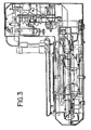
- the slide carousel 24 supports slide supports 26. Heated air is supplied to the apparatus via a resistive heating element and a blower. The heated air recirculates within the apparatus as shown in Figure 3 .
- the support plate 22 also supports a remote device microcontroller 36 on the automated biological reaction apparatus, power supply 24 and fluid and pneumatic valves 62.
- the remote device microcontroller printed circuit board 36 is generally a processor and can be replaced by a standard computer.
- the remote device microcontroller printed circuit board 36 interfaces, via an RS-485 line, with a host device 32, as described subsequently in FIGS. 5A-5C .
- the lower section 6 includes support plate 40 upon which are supported accessories such as power supply 42 and buffer heater 44.
- the stepper motor 48 rotates the slide carousel 24, engaging drive belt 25 engaging the drive sprocket of the slide carousel 24.
- the annular waste liquid sump surrounds the shroud and is supported on the bottom of plate 22. The waste reagent and rinse fluids are collected in the sump and passed to a drain through an outlet tube in the sump bottom (not shown).
- Rinse and Liquid CoverslipTM (which is light oil substance used to prevent evaporation of the aqueous solutions on the slide) spray blocks 60 are supplied with fluid through conventional solenoid valves 62 (see also FIG. 6A , 248F-J).
- Buffer heater temperature sensor 66 mounted on buffer heater 44, controls the heat energy supplied to the buffer heater 44.
- Slide temperature monitoring sensor 68 mounted on support plate 22, controls the temperature of the air in the apparatus by controlling energy supplied to annular heater elements 27.
- Power supply 42 provides power to the stepper motors 14, 48 and control systems.
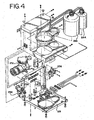
- FIG. 4 is a left front isometric view of the bulk fluid module system 230 which is included in the automated biological reaction system 150.
- the bulk fluid module 230 includes an air compressor 232, a pressure relief valve (prv) 238, cooling tubing 231, a water condenser and filter 234, an air pressure regulator 236, a bottle containing wash buffer 246, and a bottle containing Liquid CoverslipTM 244.
- the air compressor 232 provides compressed air which is regulated by the pressure relief valve (prv) 238 to 25 psi.
- the air passes from the compressor 232 through the cooling tubing and enters the condenser and filter 234. From the condenser and filter 234, the air passes to the pressure regulator 236.
- the pressure regulator 236 regulates the pressure to 13 psi.
- the air maintained at 13 psi, is supplied to the wash buffer bottle 246 and the Liquid CoverslipTM bottle 244 and the staining module 167 (see FIG. 2 ). Water condensing out of the compressed air passes out of the condenser and filter through the pressure relief valve and exits the bulk module. Wash buffer and Liquid CoverslipTM are supplied to the staining module.
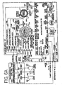
- the automated biological reaction system 150 is segmented into a host device 32, which includes a typical personal computer, and at least one remote device 166, which includes the automated biological reaction device in FIGS. 2 and 6A .
- a host device 32 which includes a typical personal computer
- at least one remote device 166 which includes the automated biological reaction device in FIGS. 2 and 6A .
- Each remote device 166 on the network has a unique address so that each remote device 166 may be identified and individually controlled by the host device 32.
- the automated biological reaction system 150 can support up to eight remote devices 166 due to the 3 bits (values 0-7) dedicated to the addressing of the remote devices 166.
- a rotary switch is provided on the remote device 166 to allow for the identification and the changing of the 3 bit address for each remote device 166. All host messages include this address in them. as described subsequently in FIG. 5B .
- the number of remote devices 166 can be smaller or larger than eight, depending on the capacity requirements or practical limitations of the laboratory in terms of space.
- the remote devices 166 may be immunohistochemistry staining modules, another type of instrument that performs a different type of staining, or another type of medical testing device.
- Communication between the host device 32 and the remote devices 166 is accomplished using a serial RS-485 link, which serves as a network, that supports one host and up to 32 remotes at one time.
- addressing of the remote devices 166 allows up to 8 remote devices to communicate with the host at one time.
- the RS-485 link has at least two pairs of lines for communication, one pair for transmitting and one pair for receiving.
- the remote devices 166 which are connected to the network "hear" the host messages but do not "hear" other remote messages. In the preferred embodiment, all communications begin with a host message, followed a short time later by a response by a remote device 166 if present.
- the host device 32 If the host device 32 sends a message and there is no remote device 166 to respond to it, the host device 32 times out. In this manner. the communication provides a simple, collision-free link between the host device 32 and the remote devices 166.
- the remote devices 166 in addition to communicating with the host device 32, address each other. For example, the remote devices 166 address each other using the unique 3 bit address, sending information about staining runs, which are described subsequently.
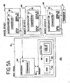
- the host device 32 is a typical personal computer with a processor 152 which includes a comparator 154 for comparing values in the processor.
- the processor 152 is also in communication with memory devices 156, including nonvolatile memory devices such as a ROM 158, volatile memory devices such as a RAM 160, and a hard disk 162. Any of the memory devices may contain databases or look-up tables; however, in the preferred embodiment, the hard disk 162 contains the databases or look-up tables 164.
- the remote device 166 includes a processor, such as a microcontroller 36 wherein the microcontroller 36 has a comparator 170 for comparing values in the microcontroller 36. In an alternative embodiment, the microcontroller 36 in the remote device 166 is replaced by a personal computer.
- the microcontroller 36 is manufactured by Dallas Semiconductor, model number DS2251T 128K Soft microcontroller module.
- the microcontroller 36 has two lines (serial to PC, serial to next inst) to facilitate communication between the host and the remote devices.
- the host device 32 through the processor 152, is connected to the serial to PC pin of the microcontroller 36 of remote device 1 ( 166 ).
- the serial to next inst line of the microcontroller 36 of remote device ( 166 ) is connected to the serial to PC pin of remote device 2 ( 166 ).
- the connections follow similarly through remote device N ( 166 ). In the preferred embodiment, there are up to 8 remote devices on the network.
- the serial to next instrument line is connected to a terminator 171.
- the terminator 171 can thereby match the impedance of the network.
- the serial to PC line and the serial to next remote device line need only be connected to each other for the remote device 166 to be removed from the network. Thereby, the network does not "see” that remote device 166 and is effectively removed from the network.
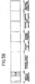
- FIG. 5B there is shown a format of the addressing for the host and remote devices 166 described in FIG. 5A .
- Both the host device 32 and the remote devices 166 have the same format and are distinguishable from one another only by the messages in their fields.
- Both the host device command and the remote device response for a given message transaction contains the same message.
- the first character is the start of message character.
- the 8 th bit is always set to 1, the lower 3 bits contain the address of the remote and bits 3-6 are unused.
- the host device 32 addresses the remote device 166 in this manner.
- the addressed remote responds in kind with its own address here.
- the message length is 2 characters in length. This number indicates the number of characters in the entire message. This includes the start of message character and the message checksum character. This is the actual number of characters transmitted as seen through the host/remote serial ports.
- the message ID is one character in length. It tags a message with a number (0-255) that identifies it from other messages. The message ID provides identification for message acknowledges from the remote and provides safe message retry processing in the remote. The message ID is implemented by incrementing a number until it reaches 255, and thereafter returning to 0. Each successful message transmission causes the message ID to increment by 1. Retransmitted messages from the host, due to unsuccessful acknowledgments from the remote, are repeated with the same message ID as the original message.
- the message command is 1 character in length.
- the message command indicates to the remote the type of command the message command data pertains to.
- this field is used to tell the host device 32 how the request was received.
- the message command data is of variable length. It contains additional message data, depending on the particular host command. The size of the message command data is dictated by the message length, described previously. After removing the other fields from around this field, the remainder is the message information. Since message commands may not require message command data, this field may not always be used.
- the message checksum is 1 character in length. It contains the computed checksum of all characters in the message, starting with the start of message character and including all message characters up to, but not including, this checksum field. No message is processed if the message checksum does not match the actual computed checksum of the received message.
- FIG. 5C there is shown a communication transmission protocol between the host device 32 and remote devices 166 described in FIG. 5A .
- Messages are downloaded from the host device 32 to the remote devices 166.
- the host device initiates a message to send to a remote device ( 172 ).
- the host device allocates memory to hold a message 176 and loads the message into memory 178.
- the host device 32 then places the message at the top or at the bottom of the queue 180, 182, depending on the priority of the message. Since the queue is first-in-first-out, the messages at the bottom of the queue go out first. Therefore, if a message must be sent out immediately, it is placed at the bottom of the queue 180.
- the message is placed at the top of the queue 182. Thereafter, the messages are sent to the message queues for each of the up to eight remote devices 184, 186, 188, 190, 192, 194, 196, 198.
- a message is sent from the host device 32 to a remote device 166
- messages are sent periodically through the use of a timer.
- the timer is turned off 200 and all of the messages from the specific queue as indicated by the host are sent 202. If the host device 32 determines that the message does not need to be rapidly sent, the message is sent in the predetermined sequence based on the timer by sending it in the predetermined sequence 206.
- the host uses the tab position 204, which indicates which remote to send the message to.
- the remote device 166 includes a microcontroller 36.
- the microcontroller 36 has a user switch and LEDs line which connects to the status PCB (printed circuit board) 294.
- the status PCB 294 is the interface-to the user for the remote device 166 and includes three LEDs (light emitting diodes) for power determination, error notification and notification of a run in progress.
- the status PCB 294 also includes a switch 295, such as a push-button switch, which is used for testing of various functions.
- the microcontroller 36 executes the last set of instructions (described later as macro 0) that was entered in the microcontroller 36.
- Macro 0 is a list of instructions which are used to execute a staining run in the remote device 166. For testing purposes, operators may wish to review the last staining run. In order to do this without requiring the operator to download the program from the host device 32 to the remote device 166 (which may be in a different location), the operator may depress the push-button switch 295. In this manner, the operator may repeatedly execute the last run at the touch of a button.
- the microcontroller 36 also has a slide fan out connection which is used to control the blower fan 4.
- the blower fan 4 recirculates air to heat the slides on the slide carousel 24 of the remote device 166 by forcing air over the heater 302 and then over the slides.
- the slide temp in connection on microcontroller 36 is connected to the slide temperature monitoring sensor 68 which senses the temperature of the air.
- the slide temperature monitoring sensor 68 is positioned in the path of the heated air and thereby sends information to the microcontroller 36 when to turn the slide heater 302 on and off.
- the slide heater out connection is connected to the slide heater 302 which, as discussed previously, heats the air in order to elevate the temperature of the slides.
- the host device 32 downloads to the remote device 166 both the sequence of steps in a run program, and the sensor monitoring and control logic called the run rules.
- One of the environmental parameters is the upper and lower limit of the air temperature of the slides (used for heating the slides). If, during a run, the environmental temperature is below the lower limit, as indicated by slide temperature monitoring sensor 68, the slide heater 302 is turned on. Likewise. if the environmental temperature is above the upper limit as indicated by slide temperature monitoring sensor 68, the slide heater 302 is turned off.
- the power supply 24 supplies both 24 VDC and 5 VDC to the applicable 24 VDC and 5 VDC connections.
- the 24 Volt power supply 24 is used to power the motors 14,48 which move the slide carousel 24 and the reagent carousel 8, and the valves 248A-J, which are described subsequently.
- the 120 VAC input is sent through a power switch 310, a fuse 308 and a filter 306 to the AC In connection of the power supply 24.
- the 120 VAC input is also used to power the slide heater 302, buffer heater 44 and compressor 232 of the bulk fluid module, which are described subsequently.
- the serial to PC line and the serial to next remote device line are described with reference to FIG. 5A .
- the tub overflow in line receives input from a conductivity sensor 255 which senses the level of the waste in the tub 254.
- the conductivity sensor 255 When the conductivity sensor 255 senses that the waste line is above a predetermined level, the conductivity sensor 255 notifies the microcontroller 36, which in turn sends a status message to the host device 32. The operator is first given an opportunity to clear the waste from the tub 254. If the tub 254 is still above the predetermined level, the run is stopped.
- the buffer heater 44 is used to heat the wash buffer before it is placed on the slides since it has been determined that better results are achieved by heating the wash buffer to the temperature of the tissue on the slide.
- the buffer heater 44 consists of a cast aluminum block 250 with a spiral tubing 251 inside the block. When the wash buffer flows through the tubing 251 through the block 250, the temperature of the wash buffer will be the temperature of the aluminum block 250 upon exit from the tubing 251.
- a buffer heater temperature sensor 66 is used which is physically placed on the aluminum block 250.
- the microcontroller 36 receives the buffer temperature sensor input via the buffer temp line and can thereby control the temperature of the buffer heater 44 by turning on and off the buffer heater 44 via the buffer heater line on the PCB microcontroller 36.
- the fluid valves 248A-J for the Liquid CoverslipTM and the wash buffer are controlled by the fluid valve connections. There is a separate pair of wires (power and ground) for each valve 248A-J shown in FIG. 6A which are omitted for ease of display. Each valve 248A-J is a relay which is activated by the microcontroller 36. The volume adjust 266, dual rinse top 263, and two dual rinse bottom 264 devices will be described subsequently in FIGS. 7-9 . Further. there is a slide door optical sensor 258 which is input to the slide door switch in line connection and which is used to determine if the front door 256 of the remote device 166 is open.
- This sensor 258 is used for safety reasons so that, if the front door is open and remains open for five minutes, the slide carousel 24 does not move. Moreover, there is a second optical sensor, the upper level optical sensor 262, which is used to determine if the upper chassis on the remote device 166 has been opened.
- the dispense cylinder 282 uses the dispense cylinder extend and the dispense cylinder retract so that the dispense plunger extends and retracts the fluid dispensers. Using air via the system air line, the dispense cylinder 282 is pushed out by using the dispense cylinder extend line.
- the microcontroller 36 controls the air valves 248A, 248B so that the relay corresponding to the dispense cylinder extend line is activated. In this manner the dispense cylinder 282 pushes the fluid dispenser down, as described subsequently in FIGS. 12A-12C , thereby dispersing reagent.
- the dispense cylinder retract valve 248B is activated using the system air line so that the fluid dispenser is pushed to retraction. Additionally, an extension spring is used to help speed the retraction process, as described subsequently.
- An optical sensor is used to determine if the dispense is extended, and thereby activated. When the dispense cylinder 282 is extended, the optical sensor is tripped validating that the dispense operation has occurred.
- Motors 14, 48 move the slide carousel 24 and the reagent carousel 8, and are connected to the slide motor out connection and the reagent motor out connection, respectively.
- the motors 14, 48 are typically stepper motors.
- Sensors 274, 286 are placed in proximity to the slide carousel 24 and the reagent carousel 8 in order to determine the "home" position of each.
- the slide carousel home sensor 274 is inductive-type and senses a piece of metal placed underneath the slide designated as the "home" position. When the "home" position is found, the sensor 274 sends a signal to the slide home in line of the microcontroller 36.
- the sensor 286 also is an inductive-type of sensor.
- the reagent tray 10 has a large flat metal ring around the entire tray except for the home position.
- the sensor 286 senses an absence of metal, this is determined to be the home position thereby indicating to the microcontroller 36, via the reagent home in connection, that the home position is found.
- the sensor 286 senses the reagent tray 10, rather than the reagent carousel 8, since the user may remove the reagent tray 10. Additionally, since the sensor 286 looks for the absence of metal for the home position, the absence of the reagent tray 10 may be tested by looking for the absence of metal in two consecutive positions.
- System pressure is determined via the system air line which directly feeds into a transducer 290.
- the transducer 290 generates an analog voltage which is proportional to the pressure.
- the output of the transducer 290 is then sent to an analog to digital converter (ADC) 292 whose output is sent to the microcontroller 36 via the system pressure in connection.
- ADC analog to digital converter
- the transducer 290 and ADC 292 combination indicates to the microcontroller 36 the exact pressure. Therefore, the microcontroller 36 can determine both whether the pressure is too low and too high. In either instance, the microcontroller 36 sends an error message and shuts down the run.
- the bulk fluid module 230 includes the compressor 232 which pressurizes the air to up to 90 psi.
- the compressed air is sent to a filter 234 in order to filter out water and other contaminants.
- Pressure is regulated in a two-step fashion. First, the pressure is regulated at the compressor to approximately 25 psi ( ⁇ 1psi) via a spring diaphram (prv) 238.
- the prv 238 is manufactured by Norgren in Littleton, Colorado, part number NIP-702 with a plastic bonnet. Second, the pressure is fine-tuned to 13 psi using an air pressure regulator 236.
- the pressure regulator 236 is very accurate in terms of precise pressure regulation over long periods of time.
- the compressor 232 need not overwork itself since the prv 238 maintains the pressure at the output of the compressor to 25 psi by opening and letting out excess pressure when the pressure exceeds 25 psi.
- Water and particulates, which are filtered out of the air via the filter 234, are sent to a waste receptacle.
- the compressed air pressurizes the Liquid CoverslipTM and wash buffer bottles 244, 246 so that when the valves 248F-J are opened corresponding to the Liquid CoverslipTM, volume adjust, dual rinse top, dual rinse bottom lines, the pressure is already on the line and the fluid may flow.
- the compressed air is used for the dispense cylinder extend line, the dispense cylinder retract line, the mirror air cylinder line, the vortex mixers line, and the bar code blowoff/airknife line.
- Filters 240 are used at the outputs of the Liquid CoverslipTM and wash buffer bottles 244, 246 in order to remove particulates which may get caught in the valves 248.
- the mirror air cylinder line is used to turn the mirror cylinder 278 so that the bar code reader 276 either reads bar codes on the slides of the slide carousel 24 or bar codes on the fluid dispensers on the reagent carousel 8.
- the output from the bar code reader 276 is input to the microcontroller 36 via the bar code serial I/O connection.
- a flow restrictor 268 In between the valve 248C for the mirror air cylinder line and the mirror cylinder is a flow restrictor 268.
- the flow restrictor 268 slows the flow of air in the line while still maintaining the 13 psi pressure on the line. In this manner. this moves the mirror slower than would otherwise be done without the restrictor 268.
- the vortex mixers 271 likewise operate off of the 13 psi system air line to mix the contents on the slide.
- the vortex mixers 271 may be used in a single stream or in a dual stream mode. In particular, a single stream of air or a dual stream of air may be used to mix the contents on the slide.
- restrictors 268 are used in the vortex mixers lines in order to reduce the flow of air. In this manner, when the vortex mixers 271 are used to mix the contents on the slide, the fluid does not blow off the slide and the mixers do not dry any particular spot on the slide.
- the bar code blowoff/airknife 267 is used to blow air on the portion of the slide which contains the bar code. In this manner, the bar code is easier to read. Further, fluid can be kept on the slide better due to surface tension if fluid near the edge of the slide is removed.
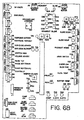
- FIG. 6B there is shown a circuit board connection diagram for the microcontoller.
- the sensors and motors for the remote device 166 plug into this board which in turn is in communication with the microcontroller.
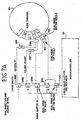
- FIG. 7A there is shown a block diagram of the dual rinse and volume adjust components 263. 264, 266 of the remote device 166 in FIG. 6A .
- a run is generally executed in a series of steps including the following: reagent is applied to the slide, Liquid CoverslipTM is applied to the slide, the reagent reacts with the tissue on the slide, a different reagent is applied to the slide, Liquid CoverslipTM is applied to the slide, the different reagent reacts with the slide, etc. After the reagent reacts with the slide, but before the next reagent is applied to the slide, the excess reagent which did not react with the sample should be removed from the slide.
- the residual reagent from the previous step is washed from the sample using a wash buffer. Washing may be achieved using a dual rinse device which executes a dual rinse step using a dual rinse top valve 248H and a dual rinse bottom valve 248I, as shown in FIG. 7A .
- the microcontroller 36 controls the valves so that the wash buffer pulses the slide with the dual rinse top valve 248H and one of the dual rinse bottom valves 248I or 248J consecutively.
- the microcontroller 36 turns on the dual rinse top valve 248H, then one of the dual rinse bottom valves 248I or 248J, and so on. As described subsequently, there are two dual rinse bottom valves 248I or 248J in order to achieve the consistency pulse.
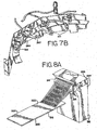
- FIG. 7B there is shown a perspective view of the dual rinse top and dual rinse bottom, volume adjust/coverslip, airknife/barcode blowoff and vortex mixers.
- the configuration is in the form of a boomerang whereby the boomerang follows the curved portion of the slide carousel 24.
- FIG. 8A there is shown a side isometric view of one embodiment of the wash block 312 which employs the dual rinse top nozzle 263 and dual rinse bottom nozzle 264 as shown in FIG. 7A .
- the wash block 312 comprises a lower set of nozzle outlet openings 316 corresponding to the dual rinse bottom nozzle 264 and an upper set of nozzle outlet openings 314 corresponding to the dual rinse top nozzle 263.
- the dual rinse bottom nozzle 264 and dual rinse top nozzle 263 each comprise a plurality of openings.
- the dual rinse bottom nozzle 264 and dual rinse top nozzle 263 each comprise a single opening.
- these openings 314, 316 direct streams of pulsed rinsed fluid towards one or the other of the longitudinal edges 322 of the slide 318.
- the streams of the pulsed rinsing fluid, from each of the lower and upper sets of nozzle outlet openings 314, 316 preferably impact the slide 318 at the rinse fluid impact zone 320 which is upstream on the slide 318 from the tissue sample (not shown) positioned thereon.
- Positioning of the wash block 312 is important due to the fragile nature of the tissue sample positioned on the slide.
- the upper set of nozzle outlet openings 314 is constructed so that the associated streams of rinse fluid are off-set at an angle from the longitudinal center line of the slide so that the pulsed streams of rinse fluid are directed toward one of the longitudinal edges of the slide 318.
- the lower set of nozzle openings 316 is constructed so that the associated streams of rinsing fluid are also off-set at an angle from the longitudinal center line of the slide so that the pulsed streams of rinse fluid are directed toward the other one of the longitudinal edges of the slide 318.
- the wash block 312 directs streams of pulsed rinsing fluid, for example from the lower set of nozzle openings 316 toward a single longitudinal edge of the slide and after completion then directs streams of pulsed rinse fluid, for example from the upper set of nozzle openings 314, to the other longitudinal edge of the slide.
- This procedure is repeated, via control of the valves 248H-J using the microcontroller 36, and has the effect of rinsing the previous layer of rinse fluid and chemicals off of the slide.
- each of the dual rinse top nozzle and dual rinse bottom nozzle 263, 264 forms an angle with the horizontal of between 15 and 35 degrees, preferably substantially 35 degrees for the dual rinse top nozzle 263 and substantially 25 degrees for the dual rinse bottom nozzle 264, as described in FIGS. 8B and 8C .
- the angle of the slide is substantially horizontal (.5 degrees to 1.25 degrees) so that the wash buffer both washes the excess reagents off of the slide and also flows off of the slide.
- wash buffer After cleaning the excess reagent off of the slide, a precise amount of wash buffer should be applied to the slide. Ordinarily, 270 ⁇ L is the optimal amount of buffer which should be placed on the slide for the next step. In executing the dual rinse step, there is residual wash buffer on the slide: however, the amount of wash buffer left on the slide varies considerably. In order to consistently leave a specific amount of fluid on the slide, the microcontroller 36 executes a consistency pulse.
- the consistency pulse consistently leaves an amount of fluid on the slide with variation in amount lower than a shorter pulse, and the consistency pulse cleans the slide of excess reagents.
- the consistency pulse is a pulse of wash buffer which is executed for a longer period of time than the individual pulses of the dual rinse step.
- the tubing containing the wash buffer is pressurized. Because of this pressure and because of the turning on and off of the wash buffer valves 248H-J, there is a pressure wave effect generated in the wash buffer tubing (i.e., there are "reflections" with a certain frequency that travel through the tubing based on, among other things, the length and geometry of the tubing). Therefore, one cannot consistently determine where one is on the wave.
- the consistency pulse turns the valve on for a period of sufficient time and/or for a sufficient strength in order to let the wave effect minimize within the tubing.
- This sufficient amount of time amounts to a few periods of the frequency of the reflected wave. Since the reflected wave is a decaying sinusoid. after a few periods, the wave is no longer a factor in the consistency pulse.
- the consistency pulse is therefore an extended burst of either the dual rinse top nozzle 263 or the dual rinse bottom nozzle 264 for a period longer than the dual rinse step. For example, as describe in FIG. 9 in more detail below, the period for a pulse during the dual rinse step is 60 mSec whereas the period for the consistency pulse is 300 mSec.
- the momentum of the consistency pulse should be greater than that during the dual rinse step.
- the increase in momentum of the pulse is achieved by increasing the volume of wash buffer flow using two dual rinse bottom valves 248I and 248J, as shown in FIG. 7 . as opposed to using only one dual rinse valve 248I or 248J during the dual rinse step. In this manner, the stream of wash buffer with an increased momentum is sent across the slide with the result that the residual volume of buffer left on the slide after the consistency pulse is lower and also has a lower variation. If a pulse of lower momentum is used. more solution is left on the slide due to interaction with the surface tension of the slide.
- the increase in volume and subsequent increase in momentum for the consistency pulse may be achieved using a valve which has an opening which is larger than the opening of the valves 248H-J used during the dual rinse step.
- the consistency pulse therefore has a strong flow out of the nozzle, generating a laminar, not turbulent, flow on the slide. The laminar flow then washes off the slide, consistently leaving an amount of fluid on the slide.
- the consistency pulse is consistent, not only from run to run on an individual machine, but also from machine to machine as well. Therefore, machine may be interchanged without the need for recalibrating the system to determine the amount of buffer left on the slide.
- the dual rinse bottom nozzle 264 should be used rather than the dual rinse top nozzle 263.
- the angle of the dual rinse bottom nozzle 264 is less than the angle for the dual rinse top nozzle 263; therefore, the less steep the angle, the more likely the buffer will flow off of the slide, not interacting with the surface tension of the slide. For example, using a dual rinse top nozzle 263 with a single valve leaves approximately 275 ⁇ 40 ⁇ L on the slide whereas using a dual rinse bottom nozzle 264 with a dual valve leaves approximately 180 ⁇ 20 ⁇ L on the slide.
- the consistency pulse may be used in several ways.
- the first way is for the consistency pulse to leave a minimal amount of wash buffer on the slide with minimal variation from run to run and machine to machine (180 ⁇ 20 ⁇ L) for any given instrument.
- this variation of ⁇ 20 ⁇ L is across all machines so that, in the event that one machine must be replaced by a second machine, the variation is small enough so that the amount of fluid left on the slide is within acceptable parameters.
- the variation from run to run within a single machine is approximately ⁇ 10 ⁇ L; therefore, once the machine is calibrated (and the amount of volume dispensed from the volume adjust, as discussed , subsequently, is determined to achieve a total volume of 270 ⁇ L), the fluid on the slides for a particular machine does not vary significantly run to run.
- the modification of the consistency pulse is done by using a time longer than the individual dual step pulse, the dual rinse bottom nozzle 264, and the two valves 248I and 248J; after the consistency pulse step, the required amount of buffer on the slide (as determined by experiment) may be added using the volume adjust 266, which-is described subsequently, with extreme precision.
- the consistency pulse may be used to leave an amount greater than a minimal amount, while still having a low variation in the amount left on the slide.
- the operator may adjust the amount of momentum of the pulse, the duration of the pulse, the angle of the outlet nozzle with respect to the slide, and the angle of slide with respect to horizontal.
- the outlet of the nozzle may be designed with an angle which is less than the angle of the dual rinse bottom nozzle. In this manner, the operator may tailor the amount left on the slide depending on the amount and variance of the buffer necessary for the experiment.
- the volume adjust is used. as shown in FIGS. 7A and 7B .
- the microcontroller 36 turns on the valve 248G for the volume adjust line to place buffer on the slide.
- the volume adjust line has a restrictor 268 which reduces the volume flow of the wash buffer through the line. This is done so that the buffer does not disturb the tissue on the slide since the needle of the volume adjust nozzle 388 is directly above the slide and the wash buffer is dropped onto the slide. A precise amount of buffer is able to be placed on the slide.
- the amount of volume placed on the slide may be adjusted by changing the dial nozzle which controls the amount of time the valve for the volume adjust line is open. In the alternative, the amount of time the valve is open may be adjusted using a potentiometer.
- the volume adjust 266 is more accurate when it is turned on for more than 60 mSec. Operating the volume adjust 266 less than 60 mSec makes the dispensing of the buffer less accurate. This is due to the fact that the turning on and off of the valves, which is controlled by the microcroller, is interrupt driven. There is a window of accuracy of approximately 10 mSec when turning on/off the valves ( e.g., if the volume adjust 266 is to be turned on for 50 mSec, the actual time in which the valve for the volume adjust is turned on is between 40 mSec and 50 mSec).
- the consistency pulse should leave a volume of fluid on the slide low enough so that the volume adjust may be turned on for more than 60 mSec (which is determined to be the minimal amount of time in which the accuracy of the volume adjust is acceptable).
- the consistency pulse is designed to leave a minimal amount of fluid on the slide by using the dual rinse bottom nozzle 264 and the two valves 248I and 248J.
- the volume on the slide is increased to approximately 270 ⁇ L.
- FIGS. 8B and 8C there are shown side views of the angles of the dual rinse top nozzle 263 and dual rinse bottom nozzle 264, respectively, as shown in FIG. 8A .
- the angle, as described previously, is 35 degrees from the horizontal for the outlet of the dual rinse top nozzle ( 263 ) is 25 horizontal for the outlet of the dual rinse bottom nozzle ( 264 ). These angles may be varied in order to modify the amount and/or variation of fluid left on the slide after the consistency pulse.
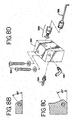
- FIG. 8D there is shown a side view of one embodiment of the volume adjust as shown in FIG. 7A .
- the needle 388 of the volume adjust is composed of a stainless steel with a 90 degree needle. Fluid therefore goes at a downward angle and drops onto the slide, thereby allowing for greater control of the placement of the fluid.
- the connector pieces which connect the needle 388 to the acrylic block 392 of the volume adjust are also composed of stainless steel. The stainless steel is used since it does not react with the wash buffer.
- a connector 394 which connects to the volume adjust line of FIG. 6A .
- At the side of the acrylic block is a connector 396 which connects to the Liquid CoverslipTM line of FIG. 6A .
- FIG. 9 there is shown a flow chart of the dual rinse, the consistency pulse and the volume adjust steps.
- one of the dual rinse bottom valves (248I or 248J ) is first turned on 324, the microcontroller 36 waits for 60 mSec 326, and the dual rinse bottom valve (248I or 248J ) is turned off 328. The microcontroller 36 then delays for 30 mSec 330.
- the dual rinse top valve ( 248H ) is then turned on 332, the microcontroller 36 waits for 60 mSec 334, and the dual rinse top valve ( 248H ) is turned off 336.
- the microcontroller 36 then delays for 30 mSec 338. This sequence is repeated two times 340.
- the microcontroller 36 waits 1100 mSec 342. Then, the dual rinse top valve ( 248H ) is turned on 344, the microcontroller 36 waits for 60 mSec 346, and the dual rinse top valve ( 248H ) is turned off 348. The microcontroller 36 then delays for 30 mSec 350. One of the dual rinse bottom valves (248I or 248J ) is first turned on 352, the microcontroller 36 waits for 60 mSec 354, and the dual rinse bottom valve (248I or 248J ) is turned off 356. The microcontroller 36 then delays for 30 mSec 358. This sequence is repeated four times 360.
- the dual rinse top valve ( 248H ) is turned on 362, the microcontroller 36 waits for 60 mSec 364, and the dual rinse top valve ( 248H ) is turned off 366. The microcontroller 36 then waits 1200 mSec 368.
- the dual rinse step begins with a bottom-top, bottom-top rinse cycle, and then a top-bottom, top-bottom, top-bottom, top-bottom rinse cycle. In this manner, the slide is cleaned better.
- This switching of the dual rinse step starting with one set of nozzles (in the preferred embodiment, the dual rinse bottom valve), and in the next step, starting with the other set of nozzles (in the preferred embodiment, the dual rinse top valve), allows for quicker cleaning of the slide while using less buffer.
- the number of pulses (top-bottom or bottom-top) and the amount of buffer sent in the pulses are varied. Rinsing removes excessive reagent in the slide and the tissue, which in turn will reduce the background staining on the slide and aid in analysis of the slide.
- 6.5 to 7.5 mL of buffer should be used in the dual rinse step. More than 7.5 mL in the dual rinse step uses an excessive amount of buffer (i.e ., one may run out of buffer during a staining run), and may limit the amount of dual rinse steps performed in one run. Moreover, by experimentation, the dual rinse step should end by using the bottom valve and bottom nozzle. This is so that, the consistency pulse, which also uses the bottom valves, is run more consistently.
- both the dual rinse bottom valves (248I and 248J ) are turned on 370, 372, the microcontroller 36 then delays 300 mSec 374, and both the dual rinse bottom valves (248I and 248J ) are turned off 376, 378.
- the valve 248G for the volume adjust line is turned on 382.
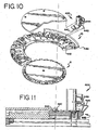
- FIGS. 10 and 11 illustrate the manner of mounting a fluid dispenser 400 in a reagent tray which is engaged in the reagent carousel 8.
- the foot 440 is initially inserted into a circular U-shaped groove 442 formed in the reagent tray 10.
- the foot is inserted into a rectangular shaped groove.
- Groove 444 of spring member 448 engages a circumferential lip 446 of the reagent tray 10.
- FIG. 11 shows a cross sectional view of the fluid dispenser 400 after it has been mounted on the reagent tray 10 showing in particular the manner in which foot 440 fits into groove 442 and showing the flexing of spring member 448 to hold the fluid dispenser 400 firmly in place.
- spring member 448 is simply bent inward slightly so that the groove 444 clears the lip 446. and the foot 440 is withdrawn from groove 442.
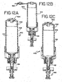
- FIG. 12A there is shown an elevational cutaway view of a prefilled fluid dispenser 400 in the extended position.
- FIG. 12B shows an elevational cutaway view of a user fillable fluid dispenser 400 in the extended position.
- the main difference between the prefilled and customer fillable dispensers is the substitution of a flip cap 402 to replace the snap cap 404.
- the fluid dispenser 400 has a reservoir chamber 410, which stores the fluid, and a dispense chamber 412, whereby the reservoir chamber 410 is above the dispense chamber 412.
- the reservoir chamber 410 is substantially in line with the dispense chamber, and in the preferred embodiment, coaxial with the dispense chamber 412.
- Previous liquid dispensers had a side by side arrangement whereby the reservoir chamber was to the side of the dispense chamber. In this configuration, the reservoir chamber was smaller and therefore held less fluid. In the present invention the reservoir chamber can be enlarged thereby holding more fluid. For example, in previous dispensers, the reservoir chamber could hold approximately 27.5 mL of fluid whereas, in the present invention, the reservoir chamber can hold approximately 34.0 mL of fluid. Ordinarily, a single dispenser is rated to give 250 shots (i.e., 250 dispenses of fluid). In order to provide the 250 shots in the previous dispensers, different types of couplers, depending on different types of reagents had to be made.
- the dispenser can provide 250 shots, regardless of the viscosity of the fluid, so that different couplers are not necessary.
- previous fluid dispensers which included a reservoir chamber 410 that was to the side of the dispense chamber 412 required a connecting or horizontal section which connected the reservoir chamber 410 with the dispense chamber 412.
- the previous design was more difficult to manufacture.
- the side-by-side design required that the molding process of the horizontal or connecting piece be carefully controlled so that all sides of the connecting piece interact correctly with the reservoir chamber 410, the dispense chamber 412, and the ball chamber 432 and nozzle 430.
- the ball chamber 432 includes a ball 426 which seats in the upper part of the ball chamber 432 during a portion of the operation of the fluid dispenser 400.
- the coupler was formed via a T-shaped chamber, i.e. a horizontal chamber abutting two vertical pieces. At the intersection of the pieces, the ball seat area was formed. In manufacturing this coupler, the consistency of the T-shaped piece varied so that the ball seat area was, at times, difficult to manufacture properly.
- the fluid dispenser 400 requires no horizontal connecting portion between the reservoir chamber 410 and the dispense chamber 412.
- the reservoir chamber 410 is on top of dispense chamber 412 and, in the preferred embodiment, the reservoir chamber 410 is coaxial with the dispense chamber 412. Since the flow is substantially in one line or vertical, the T-shaped piece is removed.
- the ball seat area is replaced by a check valve ball insert 424 which is a separate and smaller molded piece, and therefore can be controlled, from a manufacturing standpoint, better than in previous designs.
- the reservoir chamber 410 shape is as shown in FIGS. 12A and 12B .
- the reservoir shape may also be funnel-like or any other shape which drains the fluid through the connecting means between the reservoir chamber 410 and the dispense chamber 412.
- the connecting means between the reservoir chamber 410 to the dispense chamber 412 in the preferred embodiment is a valve, such as a duckbill check valve 416 which has a means to sense pressure differentials.
- the duckbill check valve is manufactured by Vernay Laboratories, Inc. in Yellow Springs, Ohio, part number X6597-E.
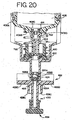
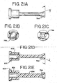
- the connecting means is any device which transfers fluid in one direction (from the reservoir chamber 410 to the dispense chamber 412) and which passes fluid based on a pressure differential. This includes using an umbrella valve or the cup check valve 792 as described in FIGS. 20-21 .
- Fluid is ejected from the dispense chamber 412 by exerting a downward force on the cap, against the force of the compression spring 418. This forces the barrel 408 downward until it reaches the stop 420 which prevents the barrel 408 from further downward movement, as shown in FIG. 12C .
- the downward force on the cap 404 is applied by the dispense cylinder extend air line, as described in FIG. 6A , or by some other means to push the barrel 408 downward.
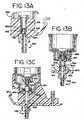
- FIG. 13A there is shown a detailed view of the ball chamber 432 and nozzle 430.
- the coupler 428 is formed where a hole in the coupler is offset for ball chamber 432 so that an inner edge of nozzle 430 protrudes into the outlet of ball chamber 432.
- Ball chamber 432 contains a ball 426 which fits loosely against the cylindrical surface of ball chamber 432 and is free to move between an uppermost position and a lowermost position. In its uppermost position, ball 426 mates with the ball check valve insert 424, thereby preventing fluid flow in the direction from nozzle 430 to dispense chamber 412. At its lowermost position, the ball 426 is restrained by inner edge of nozzle 430 and prevented from falling into nozzle 430. This does not prevent fluid from flowing from ball chamber 432 to nozzle 430. however.
- fluid dispenser 400 is in the positions shown in FIGS. 12A and 12B .
- a downward force is applied against cap 402. This overcomes the force of compression spring 418 and forces the barrel 408 downward until it reaches the top of the stop 420. thereby dispensing a predetermined volume of liquid equal to approximately 100 ⁇ L. This is equal to the liquid volume of the area that the barrel 408 moves down minus the "suck back" (which is the amount of fluid that travels past the ball on the upstroke of the barrel 408 before the ball 426 shuts off the flow).
- the fluid flows from dispense chamber 412 into ball chamber 432.
- the downward flow through ball chamber 432 forces ball 426 to its lowermost position, abutting edge 434, but this does not prevent flow in this direction and the measured amount of fluid is ejected from nozzle 430.
- the volume of fluid which flows from nozzle towards dispense chamber 412 ("suck back") while ball 426 is moving from its lowermost to its uppermost position is preselected to be a volume equal to the volume of the hanging drop left at tip at the end of the dispense cycle.
- the drip is effectively drawn back into nozzle 430 and an internal meniscus forms at tip.
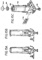
- FIGS. 13B and 13C there is shown a front and side cutaway of the lower portion of the fluid dispenser 400, respectively, in an alternative embodiment of the invention wherein the ball check valve insert 424 and ball 426 are removed.
- the piston 454 on the end of the barrel 408 has an extension piece 456 connected to it.
- the extension piece 456 moves upward as well, thereby retracting any drops on the edge of the nozzle 430.
- FIG. 13B shows the barrel is in the down position.
- the diameter of the piston and the diameter of the cavity in which the piston moves may vary in dimensions based on the needs of the liquid dispenser.
- the piston 454 has a single hole 806.
- the O-ring 810 is a tight fit with the extension piece so that the O-ring 810 travels with the extension piece. Because the O-ring 810 is not flush with the chamfer 808 (which is a cone shaped), fluid in the dispense chamber can flow down around the back side of the O-ring 810 and out through the nozzle 430.
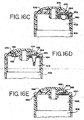
- a second O-ring 814 takes the place of the quad seal 422, as shown in FIGS. 14A-14B .
- the O-ring 810 travels with the extension piece 454, which is attached to the piston 454, until the O-ring 810 seats against the chamfer 808.
- the extension piece 454 acts as a piston extension.
- the chamfer 808 is housed inside the O-ring insert 812 and is fixed during movement of the piston.
- the O-ring insert 812 is connected to the coupler 428.
- the fluid travels with the extension piece 454, and the drop at the end of the tip of the dispenser travels with the fluid due to surface tension. Therefore, the hanging drop is pulled back into the nozzle 430. Moreover, with the barrel 408 in the up position, fluid does not travel through the holes 806 due to the O-ring 810 seating inside the chamfer 808. In this embodiment, the ball and ball check valve insert is not necessary.
- FIGS. 14A and 14B there are shown exploded views of a cutaway of a prefilled and user fillable fluid dispenser 400, respectively. Differences between the prefilled and the user fillable fluid dispensers include: (1) the snap cap 404, as shown in FIGS. 14A and 14B ; the barrel 408 being transparent in the user fillable fluid dispenser; and (3) the lack of an evaporation ring 405 in the user fillable fluid dispenser. Fluid can be filled into the reservoir through a fill hole and subsequently closed using a snap cap 404 in order to close the system. For prefilled fluid dispensers, the snap cap 404 is permanently attached over the fill hole after filling.
- the fill hole and the snap cap 404 are matched using a luer fitting design in order to be a tight seal, as shown in FIG. 16 .
- the user fillable fluid dispenser 400 utilizes a living hinge design and luer slip design between the fill hole and the flip cap 402.
- the cap 406. as previously described, is sonically welded to the barrel 408.
- the cap 406 also has a vent 460, which is described subsequently with respect to FIG. 16 .
- the duckbill check valve insert 414 holds the duckbill check valve 416 in place and creates a seal so that fluid cannot drip either from the dispense chamber 412 to the reservoir chamber 410 or from the reservoir chamber 410 to the dispense chamber 412.
- the duckbill check valve insert 414 has a protrusion, or a nipple, which holds the duckbill to it for ease of assembly, as shown in more detail in FIG. 17B .
- the duckbill check valve 416 which serves as a check valve, is snapped to the duckbill check valve insert 414.
- the duckbill check valve 416 is a one way valve with a high cracking pressure of between .6 to 3.0 psi. This acts to hold the fluid in the reservoir chamber 410 since the cracking pressure is greater than the head pressure of fluid in the reservoir chamber 410.
- the duckbill passes fluid from the reservoir chamber 410 to the dispense chamber 412 on the upstroke of the barrel 408 while preventing fluid to pass during the downstroke of the barrel 408.
- the duckbill check valve 416 and duckbill check valve insert 414 are seated in the lower portion of the barrel 408 as shown in FIG. 17A .
- the spring 418 is a compression spring which expands and contracts based on the movement of the barrel 408.
- the stop 420 stops the downward stroke of the barrel 408.
- the stop also holds the quad seal 422 in place during movement of the fluid dispenser 400 and composed of polypropylene.
- the stop 420 is held in place based on the compression spring 418 with the force varies based on the movement of the barrel 408.
- the stop 420 is held in place, in turn, keeps the quad seal 422 in place via a ledge 420A, as shown in FIG. 17C . on the stop 420.
- the quad seal 422 ensures that the fluid dispenser 400 is always a closed system thereby keeping the fluid dispenser 400 primed.
- the quad seal 422 is made of VitonTM rubber that is a fluoroelastomer, and is distributed by Lutz Sales, in Hanover Park, Illinois, part number QS-008-2799.
- the quad seal 422 may also be made from ethylene propylene diamonomer (EPDM).
- EPDM ethylene propylene diamonomer
- the ball check valve insert 424 is a separate part from the coupler 428 and is seated inside the coupler 428, being snapped into place by grooves in the chamber of the coupler 428 and by being seated on a ledge 428A, as shown in FIG. 17A .
- the ball check valve insert 424 has a ball seat 424A on the inside with which to engage the ball 426 on the upstroke of the barrel 408.
- Previous fluid dispensers integrated the coupler with the ball check valve insert for the ball.
- manufacturing of the coupler integrating those functions was difficult due to the fact that 3 pins, at the positions of 12:00, 3:00 and 6:00, had to come together and not distort the ball check valve insert. Therefore, processing is simplified by separating the ball check valve insert 424 from the coupler 428.
- the inner cavity 432 of the ball check valve insert 424, which engages the ball 426, may then be manufactured more easily.
- the ball 426 is made of borosilicate (which is a type of glass).
- a ball 426 composed of rubber may be used. In certain instances, a rubber ball may seat better in the plastic ball check valve insert 424, provided there is no chemical interaction of the rubber ball with the reagents.
- the duckbill check valve 416 and duckbill check valve insert 414 are placed in the lower part of the barrel 408.
- the cap 406 is welded to the barrel.
- the ball 426 is placed, the ball check valve insert 424 is snapped and then the quad seal 422 is inserted into the coupler 428.
- the stop 420 and the spring 418 are inserted into the coupler 428 and the coupler 428 is snapped on to the barrel 408.
- the barrel 408 is filled with reagent and the fluid dispenser 400 is primed.
- the cap 404 is placed on the top of the dispenser and the nozzle cap 458 is placed on the output of the nozzle 430 on the coupler 428.
- the present invention allows for easier manufacture and filling of the reagents in the fluid dispenser 400.
- Previous fluid dispensers required gluing of many pieces and sonic welding after filling the dispenser, thus requiring a certain level of skill and training.
- the fluid dispenser of the present invention requires snapping in of pieces and only the sonic welding of the vent 460 to the cap 406 and the cap 406 to the barrel 408.
- the filling of the reagents in the fluid dispenser 400 is easier in the present invention.
- the fluid dispenser is assembled except for the piston, piston guide, cap and nozzle cap. The reservoir chamber is filled with reagent. The piston and piston guide are then placed in the reservoir chamber and any leftover fluid on top of the piston is evacuated.
- the cap is sonically welded or screwed onto the top of the barrel 408.
- the cap 406 is first sonically welded to the barrel 408, and then the reagents are added to the reservoir chamber 410. In this manner, there are fewer steps in the filling of the dispenser.
- some of the more manufacturing sensitive parts are smaller, thereby making manufacturing easier.
- the material used is polypropylene. Under these conditions, smaller parts have a higher level of dimensional stability. Therefore, smaller components, such as the ball check valve insert 424 (which is, in the present invention, a separate component from the coupler 428) are able to be processed more consistently.
- FIGS. 15A and 15B there are shown side views of a prefilled fluid dispenser 400 and customer fillable fluid dispenser 400, respectively. Both types of dispensers have barcode labels which are read by the barcode reader 276, as described above.
- the snap cap 404 is replaced by a flip cap 402 which varies in two ways from the snap cap: (1) the flip cap has an attachment to the cap; and (2) the flip cap has a protrusion 402A which acts as a thumbpad to prop open the flip cap 402.
- the fluid dispenser had to be inverted in order to prime the syringe.
- the customer was required to first fill up a transfer syringe manually, push on an epindorf syringe and fill up this syringe. Then, the customer pressed this syringe into the coupler and forced fluid from the syringe through the connecting section between the reservoir chamber and the dispense chamber. The customer had to then pump the plunger, at least 6 to 8 times, holding the coupler upside-down, until fluid came out of the nozzle which did not have any bubbles. In the present invention, the customer opens the flip cap, fills the reservoir chamber 410, and closes the flip cap. The customer, without turning the fluid dispenser upside down, uses a typical syringe 459, as shown in FIG. 19A , to prime the fluid dispenser 400.
- the syringe may be manufactured by B-D Corp., in Franklin Lakes, New Jersey, size 20cc, part number BC301032.
- the syringe 459 has a restrictor 459A and an O-ring 459B.
- the restrictor 459A has an internal diameter of approximately 5 thousandths of an inch.
- the syringe 459 is placed inside the nozzle 430 of the coupler 428 and the syringe plunger is expanded to draw fluid from the reservoir chamber 410 and the dispense chamber 412.
- the barrel 408 is pushed down, and is released simultaneously when the syringe plunger is expanded. In this manner, there is significantly less waste of reagent.
- FIG. 19B there is shown an exploded view of the syringe 459 (and a syringe label 788) with a restrictor 459A and an O-ring 459B for use in the nozzle of the coupler.
- the O-ring 459B is placed on the side of the restrictor 459A that does not have the v-notch in it.
- the restrictor 459A. with the O-ring 459B side down, is placed into a holding fixture 790, as shown in FIG. 19B .
- the syringe 459 is then pressed onto the restrictor 459A for assembly.
- the restrictor 459A is made by Airlogic, in Racine, Wisconsin, part number F-2815-050 (color: lime green), with a one inch orifice for the restrictor 459A.
- the O-ring 459B is manufactured by Parker Co., in Lexington, Kentucky, part number 2-003.
- the restrictor 459A fits well in the nozzle of the syringe 459 so that the syringe 459 does not need the O-ring 459B to seat against the coupler. Because of potential differences in mold runs for the coupler 428 of the fluid dispenser 400, the O-ring 459B is used so that the restrictor 459A fits tightly against the coupler 428.
- the customer may flip the dispenser upside-down, tap the dispenser, dislodging any trapped air then pressing down on the barrel slowly to move the air bubble past the ball seat.
- the customer may then flip the coupler right-side-up and release the barrel. Good priming occurs with approximately one drop of waste.
- FIG. 15C there is shown an exploded view of a prefilled fluid dispenser with an evaporation ring 405 adjacent to the cap.
- the interaction of the vent, the evaporation ring 405 and the cap are discussed subsequently with respect to FIGS. 16A-E .
- the barcode label 784 is placed on the dispenser in order to be read by the barcode reader 276.
- the dispenser label 786 is also placed on the dispenser.
- FIG. 16A there is shown a cutaway view of the cap 406 and vent 460 of a fluid dispenser 400.
- the vent is the component adjacent the top of the cap and includes the vent area 464, vent material 466, and backing 468.
- the vent 460 is used as a means to allow air to flow both into and out of the reservoir chamber 410 ( i.e., so that the reservoir chamber can "breathe”).
- the vent 460 allows for a constant pressure in the reservoir chamber and equalizes the pressure in the reservoir chamber 410 with the pressure in the atmosphere.
- There are several ways in which to construct the vent in order to maintain a constant pressure in the reservoir chamber 410 and/or equalize the pressure in the reservoir chamber 410.
- the vent area is approximately 70 thousandths of an inch, with a vent material 466 composed of a hydrophobic material.
- a vent material 466 composed of a hydrophobic material.
- the vent area is reduced to approximately 10 thousandths of an inch, thereby reducing the amount of evaporation from the reservoir chamber 410.
- processing a fluid dispenser with a reduced vent area is more difficult due to the corresponding reduced area of the vent material.
- the vent area 464 may be any area.
- the vent material may be composed of a tighter material, thereby reducing the air flow through the vent material and reducing the amount of evaporation through the vent area 464.
- the vent material is 1 ⁇ m in the size of the mesh. Reducing the size of the mesh, such as to 25 ⁇ m, further reduces the amount of evaporation through the vent area 464.
- the vent area may be any area and a section of tape is placed across the vent area. The tape contains a pin hole whereby the vent area is effectively reduced thereby reducing the amount of evaporation.
- the cap 406 and snap cap 404 are luer fitting design so that the cap 406 and snap cap 404 portion which engage each other to seal the fill hole is conical.
- a ring or a lip 462 At the lower portion of the conical section of the snap cap 404 is a ring or a lip 462 that is used to snap the snap cap 404 into place.
- the snap cap 404 is pushed down until it locks into the cap 406.
- the snap cap 404 has a curved section 472 that abuts against a curved section of the cap thereby stopping the snap cap 404 at that point.
- the snap cap 404 also engages the cap 406 to form an air space 474 that is adjacent to the vent area.
- This air space 474 forms a ring, so that regardless of the orientation of the snap cap to the cap, a hollow section is adjacent to the vent area 464 (which is approximately 70 thousandths of an inch or less). Further, the outside diameter of the snap cap 404 is slightly smaller than the inner diameter of the cap 406 so that a small air gap 476 is formed adjacent to the air space 474 to the outside of the dispenser.
- the air space 474 serves as a path from the vent 460 to the outside atmosphere as well as serving as a buffer between the outside of the dispenser and the vent 460.
- the air gap 476 may be used in conjunction with a notch in the side of the cap, as shown in FIG. 15C . This notch allows more air into the air gap 476, in the event that the greater air flow is required. Moreover, the notch may replace the air gap 476, so that the sole means of air flow into the air space 474 is through the notch.
- the vent 460 is a hydrophobic vent which allows air to flow through the vent while keeping fluid trapped inside the reservoir chamber 410.
- the vent is composed of a filter material 466 such as a teflon material with a backing to attach the vent to the cap.
- the vent opening or area 464 as described previously, is approximately 70 thousandths of an inch.
- the pressure inside the reservoir chamber 410 is constant, even though the level of reagent may be changing inside the reservoir chamber 410 since air is allowed to flow into the reservoir chamber 410. Moreover, some reagents produce a by product of gas (called outgassing).
- the hydrophobic vent 460 allows gas through the vent 460, thereby avoiding any pressure build-up inside the reservoir chamber 410.
- previous fluid dispensers that required a piston to exert force on the fluid in the reservoir chamber 410 may be removed.
- the piston in previous designs suffered from several drawbacks.
- certain reagents such as proteins
- the interaction between the piston and the barrel rely on lubricants.
- Certain reagents are composed, in part, of detergents and the detergents interfere with the lubrication between the piston and the barrel. Both effects interfere with the performance of the fluid dispenser, thereby giving inconsistent dispensing of fluid.
- outgassing interacts with the piston either to increase the flow out of the reservoir chamber 410 or to create a compressible air gap between the piston and the main section of the reservoir chamber 410.
- quad seal 422 is coated with fluorine. Fluorine reacts with the outer layer of the quad seal 422, thereby discouraging reactions with certain types of reagents.
- the evaporation ring 405 is composed of low density polyethylene material manufactured by Whitmark (vendor part number 105060), and is 1/8 inch thick. As discussed previously, the ring acts as a barrier, making it more difficult for air to pass across the vent. In this manner, the ring acts as a restrictor (of air), thereby reducing the amount of evaporation, while still allowing the reservoir chamber 410 to breathe.
- the ring is a closed cell foam, and is inexpensive in nature.
- the ring may be composed of any material or foam that acts to restrict the air across the vent area 464.
- the ring is inserted in between the cap 406 and the snap cap 404.
- the ring should abut the vent area 464. thereby restricting the air flow across the vent area 464.
- the ring being composed of cell foam, compresses to fill up the air section 474.
- FIG. 16A there are protrusions 470 on the inside upper portion of the cap 406 which are used to align the piece of vent material.
- the vent 460 is therefore centered on top of that upper portion of the cap 406.
- FIG. 16B there is shown an underside view of the vent 460. Included with the vent 460 is a platform 468 for the vent 460, star-shaped in design, which holds the vent 460 flat. When air is passing through the vent 460, particularly when outgassing, the vent 460 has a tendency to flex which may damage the teflon in the vent. In order to minimize flexing of the vent 460, the platform 468 is adjacent to the vent.
- the surface area of the vent may still be relatively large but still have a grid support to stabilize the vent 460 during outgassing.
- the platform 466 is star-shaped due to ease of molding; however, the shape of the platform may be any design, which supports or stabilizes the vent.
- the vent may be substituted with a bi-directional valve 478 or bi-directional duckbill (or two valves or two duckbills) as another means by which to allow air to flow into and out of the reservoir chamber 410.
- the bi-directional valve 478 has a bi-directional valve insert 480 for placement of the bi-directional valve 478.
- the bi-directional valve 478 also has a hydrophobic layer which allows air to flow through the bidirectional valve 478 while keeping fluid trapped inside the reservoir chamber 410. In one direction (air flowing into the reservoir chamber 410), the bi-directional duckbill 478 has a low cracking pressure, in order to equalize the pressure in the reservoir chamber 410 when fluid is dispensed.
- the bi-directional duckbill 478 In the second direction (air flowing out of the reservoir chamber 410), the bi-directional duckbill 478 has a high cracking pressure, in order to alleviate any pressure due to outgassing.
- the bi-directional duckbill 478 allows air to flow through while keeping fluid trapped inside the reservoir chamber 410. Therefore, the bi-directional duckbill 478 allows air to flow into and out of the reservoir chamber 410 and allows for equalization of the pressure.
- a bi-directional-duckbill 478 may have less refinement in terms of control when compared to two uni-directional duckbills.
- the bi-directional duckbill 478 may be replaced by two uni-directional duckbills, as shown in FIG. 16D .
- the system becomes a three duckbill system.
- the duckbill that releases to atmosphere has the light cracking pressure
- the duckbill that allows air into the reservoir chamber has the light cracking pressure
- the duckbill check valve 416 that is down in the barrel has a medium cracking pressure.
- the duckbill check valve 416 in the barrel should be of a higher cracking pressure than the duckbill releasing air to the atmosphere so that pressure built up in the reservoir should be relieved through the lighter cracking pressure duckbill.
- vent 460 may be substituted with a uni-directional valve or duckbill 482, (made by Vernay in Yellow Springs, Ohio, part number VL-857-101) with a duckbill valve insert 484.
- the uni-directional duckbill 482 has a low cracking pressure to alleviate pressure due to outflow of fluid from the reservoir chamber 410.
- vent material is not required since the air is flowing only into the reservoir chamber.
- the vent opening 464 may be reduced to approximately 10 thousandths of an inch (from 70 thousandths of an inch as shown in FIG. 16A ).
- the snap cap 404. for prefilled fluid dispensers, or the flip cap 402, for user fillable fluid dispensers, may also be modified to include a seal 488 where the snap cap 404 or flip cap 402 engages the cap 406.
- this alternative embodiment does not have a gap 476 between the snap cap 404 (or flip cap 402) and the cap 406, but instead includes a seal 488.
- FIG. 17A there is shown a cutaway view of the lower portion of the barrel 408, duckbill check valve 416, duckbill check valve insert 414, washer 421, quad seal 422, ball 426, ball check valve insert 424 and coupler 428 of a fluid dispenser 400.
- the barrel 408 has protrusions 408A, which mate with the coupler in order to, maintain the position of the barrel 408 on the upstroke. Otherwise, if the spring pushes the barrel 408 upward too high, the seal, as provided by the quad seal 422, may be broken thereby creating an air path and causing the fluid dispenser 400 to lose prime.
- Positioned in between the stop 420 and the quad seal 422 is the washer 421.
- the washer 421 has the shape of a conventional washer with an inner diameter dimension of .180 inches, an outer diameter of .300 inches and a thickness of .020 inches. In this manner, the washer 421 is sandwiched in between the stop 420 and the quad seal 422.
- the washer 421 is made of a felt material and is treated with a lubricant, such as a medical grade silicone lubricant. Without the washer, there is a tendency for the piston of the barrel to stick after multiple upward and downward motions of the barrel. To remedy this, the washer 421, treated with a lubricant, keeps the piston lubricated, thereby keeping the movement smooth. In particular, the washer 421, which envelops the piston, allows the piston to remain lubricated as the piston moves upward and downward.
- the barrel 408 also has a flange 408B which mates with the stop 420 on the downstroke.
- the barrel 408 also has a pocket 408C, where the duckbill check valve insert 414 is inserted. This pocket acts as a funnel so that no puddles are formed at the bottom of the barrel 408 at the interaction point with the duckbill check valve 416 or duckbill check valve insert 414, thereby minimizing waste.
- the barrel 408 also has at its lower portion a piston 454 by which fluid is expelled in the dispenser 400. At the lower portion of FIG. 17A is a nozzle cap 458 for engagement with the nozzle 430 of the coupler 428.
- the nozzle cap 454 and nozzle 430 are matched using a luer fitting design in order to be a fluid tight seal.
- FIG. 17B there is shown a cutaway view of the lower portion of the barrel, duckbill check valve, and duckbill check valve insert of a fluid dispenser. As shown in FIG. 17B , there is a protrusion 414a on the duckbill check valve insert 414 in order to hold the duckbill check valve insert 414 in place.
- FIG. 17C there is shown a cutaway view of the quad seal of a fluid dispenser.
- FIG. 17D there is shown a cutaway view of an alternative embodiment of the duckbill check valve insert of a fluid dispenser. The protrusion 414a on the duckbill check valve insert 414 in FIG. 17D is placed on the upper portion of the duckbill check valve insert 414.
- FIG. 17A also shows a cutaway view of the coupler 428.
- the coupler 428 has grooves 428B in which the ball check valve insert 424 snaps.
- the grooves 428B act to prevent any leakage of fluid downward or air upward through the walls of the ball check valve insert 424 and the coupler wall.
- the coupler 428 also has protrusions 428C, which ensure that the dispenser is aligned on the reagent tray 10. For example, if the dispenser is misaligned, the dispense cylinder may not engage the dispenser properly.
- the coupler also has stabilizing bumps 428D, which reduce any rocking back and forth of the fluid dispenser 400.
- FIG. 18A there is shown a barrel 408 which has a lower section which acts as a piston 454 at its lower end, similar to FIGS. 12A-12C .
- a throughhole at the bottom of the piston 454 at the lower section of the barrel in the piston area.
- the pressure differential is such that the duckbill check valve 482 opens and fills the dispense chamber 410 with fluid.
- the duckbill check valve 482 in FIG. 18A is a duckbill check valve of low cracking pressure. Further, when the barrel is in the up position, the end of the piston 454A is closed by the O-ring seals 452 thereby sealing the bottom of the barrel 408 except for the holes 450.
- FIG. 18B there is shown a barrel 408 which has a lower section which acts as a piston 454 at its lower end, similar to FIG. 18A .
- a quad seal 422 is used instead of placing O-ring seals 452 to cover the hole 450 in the lower end of the piston 454A.
- FIG. 20 there is shown an alternative embodiment of a cutaway view of the lower portion of the fluid dispenser with a cup check valve 792.
- the lower portion of the cup check valve 792 i.e ., the cup piece 794 abuts against the piston 454 of the barrel 408, thereby disallowing liquid to pass through the lower portion of the barrel 408.
- the upper portion of the cup check valve 792 which is composed of an upper ledge 800 and side walls 802, abuts against the duckbill check valve insert 414 and the side of the piston 454.
- the cup check valve 792 operates in a manner similar to the duckbill check valve 416, as shown in FIG. 17A in that it operates based on a pressure differential.
- the cup piece 794 of the cup check valve 792 remains rigid so that the piston, and the cup piece, push the liquid out of the dispense chamber 412.
- the ball 434 in the ball chamber 432 seats against the check valve ball insert 424, as described in FIG. 13A , creating a vacuum in the dispense chamber.
- This vacuum creates a pressure in the dispense chamber and in the adjacent piston area of the barrel 408, causing the cup piece 794 of the cup check valve 792 to flex inward, so that the cup piece 794 does not abut against the piston 454.
- fluid in the reservoir chamber is allowed to pass around the cup check valve 792 and into the dispense chamber.
- the cup piece 794 is flexed inward until the pressure equalizes between the dispense chamber and reservoir chamber. As such, the dispense chamber receives fluid on the upstroke of the barrel 408. For better flexing effect due to the vacuum caused in the dispense chamber, the cup piece 794 of the cup check valve 792 should sit low in the piston 454 of the barrel 408. In this manner, the less area under the cup, the more suction effect caused by the vacuum.
- FIG. 21A there is shown a side view of the cup check valve 792.
- the cup piece 794 spreads outward at angle of approximately 71° from the horizontal.
- the cup piece 794 may be curved outward or inward, depending on the flexing needs of the cup piece 794.
- the upper ledge 800 and side walls 802 are formed to abut against the duckbill check valve insert 414 and the side of the piston 454. This upper piece may be of such a form in order to be held securely in place.
- FIG. 21B there is shown a bottom view of the cup check valve 792.
- the bottom 796 is round, in order to abut the round sidewalls of the piston 454.
- the bottom of the cup check valve 792 may be any shape that forms against the surface abutting it, in this case, the piston 454.
- FIG. 21C there is shown a top view of the cup check valve 792.
- the top 798 is round, in order to abut the round sidewalls of the duckbill check valve insert 414.
- the top of the cup check valve 792 may be any shape that forms against the surface abutting it, in this case, the duckbill check valve insert 414.
- FIGS. 21D and 21E there are shown views of the cup check valve 792 at cross-sections A-A and B-B in FIG. 21C , respectively.
- the cup piece 794 of the cup check valve 792 is forked for ease of flexing.
- the thickness and shape of the cup piece 794 may be varied depending on the flexing needs of the cup piece.
- the connecting piece 804 may be any shape that connects the upper piece of the cup check valve 792 to the cup piece 794.
- the connecting piece 804 is cylindrical so as not to interfere with the flow of fluid through the piston 454.
Landscapes
- Life Sciences & Earth Sciences (AREA)
- Health & Medical Sciences (AREA)
- Immunology (AREA)
- Pathology (AREA)
- Analytical Chemistry (AREA)
- Biochemistry (AREA)
- General Health & Medical Sciences (AREA)
- General Physics & Mathematics (AREA)
- Physics & Mathematics (AREA)
- Chemical & Material Sciences (AREA)
- Engineering & Computer Science (AREA)
- Biomedical Technology (AREA)
- Molecular Biology (AREA)
- Automatic Analysis And Handling Materials Therefor (AREA)
- Sampling And Sample Adjustment (AREA)
- Apparatus Associated With Microorganisms And Enzymes (AREA)
- Investigating Or Analysing Biological Materials (AREA)
Description
- A portion of the disclosure of this patent document contains matter subject to copyright protection. The copyright owner has no objection to the facsimile reproduction by anyone of the patent disclosure document as it appears in the Patent and Trademark Office files and records but otherwise retains all copyrights whatsoever.
- This invention relates to biological reaction systems, and more particularly relates to a method and apparatus for an automated biological reaction system.
- Immunostaining and in situ DNA analysis are useful tools in histological diagnosis and the study of tissue morphology. Immunostaining relies on the specific binding affinity of antibodies with epitopes in tissue samples, and the increasing availability of antibodies which bind specifically with unique epitopes present only in certain types of diseased cellular tissue. Immunostaining requires a series of treatment steps conducted on a tissue section mounted on a glass slide to highlight by selective staining certain morphological indicators of disease states. Typical steps include pretreatment of the tissue section to reduce non-specific binding, antibody treatment and incubation, enzyme labeled secondary antibody treatment and incubation, substrate reaction with the enzyme to produce a fluorophore or chromophore highlighting areas of the tissue section having epitopes binding with the antibody, counterstaining, and the like. Each of these steps is separated by multiple rinse steps to remove unreacted residual reagent from the prior step. Incubations are conducted at elevated temperatures, usually around 40°C, and the tissue must be continuously protected from dehydration. In situ DNA analysis relies upon the specific binding affinity of probes with unique nucleotide sequences in cell or tissue samples and similarly involves a series of process steps, with a variety of reagents and process temperature requirements.
- Automated biological reaction systems include the biological reaction apparatus and the dispensers for the reagents and other fluids used in the biological reaction apparatus. As disclosed in United States Patent
5,595,707, inventors Copeland et al. , entitled Automated Biological Reaction Apparatus, assigned to Ventana Medical Systems, Inc. which is incorporated herein by reference, the biological reaction apparatus may be computer controlled. However, the computer control is limited in that it is dedicated to and resident on the biological reaction apparatus. Moreover, the memory, which is used in conjunction with the computer control, contains data relating to the reagents including serial number, product code (reagent type), package size (250 test), and the like. - One of the requirements in a biological reaction system is consistency in testing. In particular, the biological reaction system should apply a predetermined amount of fluid upon the slide in order to consistently test each slide in the automated biological reaction apparatus. Therefore, an important focus of a biological reaction system is to consistently and efficiently apply a predetermined amount of fluid on the slide.
- Further, as disclosed in
U.S. Patent No. 5,232,664 entitled Liquid Dispenser by inventors Krawzak et al. and assigned to Ventana Medical Systems, Inc., which is incorporated herein by reference, reagents must be dispensed on the slide in precise amounts using a fluid dispenser. The fluid dispenser, which is used in conjunction with the biological reaction apparatus, should be easy to manufacture, reliable and compact in size. -
WO96/00195 -
NL8700226 -
US5226563 relates to a fluid spraying or dispensing device. The device has a sheath extending between an open first end and a second end provided with an end wall which is pierced by at least one hole. A fluid tank is slidably mounted inside the sheath and is provided with a fluid ejection device controlled by a push rod secured to the sheath, and a cover is adapted to be slidably engaged on the second end of the sheath. The cover includes at least one projection adapted to penetrate through the hole in the end wall of the sheath to enable the push rod to be actuated by pressing against the end wall of the tank. -
US5431309 relates to a liquid soap dispenser having a permanent housing which permits simplified insertion and replacement of disposable fluid reservoirs. The housing includes and actuator assembly which is cycled by a lever between first and second positions. The actuator assembly is configured to couple to a valve assembly on the reservoir so that when cycled, the valve assembly is actuated in sliding movement to dispense a quantity of fluid. The actuator assembly includes a pair of resiliently deformable fingers which act to secure the valve assembly to the actuator assembly for sliding movement therewith. The fingers are deformable to permit movement of the actuator assembly relative to valve assembly. - In accordance with a first aspect of the invention, there is provided a fluid dispenser for use in an automated biological reaction system, the fluid dispenser comprising: a barrel having a reservoir chamber and an upper portion and a lower portion; a coupler having a dispense chamber which is substantially coaxial with the reservoir chamber; a valve is adjacent to the lower portion of the barrel for transferring fluid from the reservoir chamber to the dispense chamber based on pressure differential between the dispense chamber and the reservoir chamber and operative to disallow a flow of fluid from the dispense chamber to the reservoir chamber; and a cap connected to the upper portion of the barrel; characterised in that the barrel is coupled to the coupler with at least a lower portion of the barrel moving downward into the dispense chamber of the coupler, which lower portion of the barrel acts as a piston to expel liquid from the dispense chamber.
- The fluid dispenser may have a vent adjacent to the cap. The vent includes a first means to maintain constant pressure in the reservoir chamber, a second means to maintain constant pressure in the reservoir chamber, and a space, the space being between the first and second means to maintain constant pressure in the reservoir chamber.
- The fluid dispenser may have a piston at a lower portion of the barrel, a cap connected to the reservoir chamber, a valve adjacent to the reservoir chamber, and a coupler, wherein the coupler has a dispense chamber whereby the piston moves in the dispense chamber.
- Also disclosed herein is a method of assembly of a fluid dispenser for an automated biological reaction system. The method includes the step of inserting a valve and a valve insert into the lower portion of a barrel. The method also includes the step of welding the cap to the upper portion of the barrel. The method further includes the step of placing the ball in the check valve ball seat. Further, the method includes the step of snapping the check valve ball seat into the coupler. In addition, the method includes the step of snapping the coupler and barrel together.
- Also disclosed herein is a method of filling and priming a fluid dispenser for an automated biological reaction system. The method includes the step of providing the fluid dispenser with a cap, a barrel having a reservoir chamber, the barrel being adjacent to the cap, a dispense chamber adjacent to the reservoir chamber, and a nozzle adjacent to the dispense chamber. The method also includes the step of providing a syringe with a tip and a syringe plunger. The method further includes the step of opening the cap on the fluid dispenser. The method also includes the step of filling the reservoir chamber within the fluid dispenser with fluid. In addition, the method also includes the step of closing the cap on the fluid dispenser. Further, the method also includes the step of placing the tip of the syringe inside the nozzle of the fluid dispenser without requiring the fluid dispenser be turned upside down. And, the method also includes the step of expanding the plunger of the syringe in order to draw fluid from the reservoir chamber and the dispense chamber into the syringe.
- Also disclosed herein is an automated biological reaction system has a slide support carousel drive means engaging the slide support carousel for moving the slide support carousel, a consistency pulse application station comprising, at least one nozzle for directing a stream of fluid onto a slide which is less than 35 degrees from the horizontal, and a volume adjust application station positioned above the slide for applying a predetermined amount of fluid on the slide by dropping the fluid onto the slide.
- Also disclosed herein is a method of placing a consistent amount of fluid on a slide in an automated biological reaction apparatus which has at least one rinse station, the rinse station comprising a rinse station nozzle positioned for directing a stream of fluid onto the slide and connected to tubing which is connected to at least one valve. The valve is connected to a bottle containing fluid, wherein the valve controls the flow of fluid from the bottle to the nozzle. The method includes the step of turning on the valve for supplying fluid to the nozzle and directing a stream of fluid onto the slide. The method also includes the step of waiting until the pressure is substantially equal in the tubing. And, the method includes the step of turning off the valve for supplying fluid to the nozzle.
- Also disclosed herein is a method of washing a slide in an automated biological reaction apparatus. The method includes the step of providing a rinse station comprising a first rinse station nozzle and a second rinse station nozzle, the first and second rinse station nozzles positioned to direct a stream of fluid onto the slide. The method also includes the step of directing a stream of fluid onto the slide from the first rinse station nozzle with a first momentum for a first predetermined amount of time. In addition, the method includes the step of directing a stream of fluid onto the slide from the second rinse station nozzle for a second predetermined amount of time with a second momentum. And, the method includes the step of directing a stream of fluid onto the slide from the second rinse station nozzle for a third predetermined amount of time with a third momentum, the third momentum being greater than first or second momentum, the third predetermined amount of time being greater than the first or second predetermined amount of time.
- Also disclosed herein is an automated biological reaction apparatus which includes a slide support carousel, drive means engaging the slide support carousel for moving the slide support carousel, a reagent delivery system for applying a predetermined quantity of reagent to one of the slides by movement of the slide support carousel in a reagent delivery zone, a heat zone for heating samples on the slide support carousel, and a rinse station. The rinse station comprises a first nozzle, a first valve connected to the first nozzle through tubing, the first valve connected to a bottle containing fluid. The rinse station further comprises a controller, the controller controlling the flow of fluid from the bottle to the first nozzle via the operation of the first valve, the controller opening the first valve until the pressure is substantially equal in the tubing.
- Also disclosed herein is an automated biological reaction system which includes a host device, the host device comprising a processor, a memory device connected to the processor, the memory device including a look-up table which contains steps for staining a slide, the processor creating a sequence of steps from the look-up table. The automated biological reaction system further includes a remote device, the remote device being physically separate from the host device, the remote device being in electrical communication with the host device. The remote device comprises a processor, a memory device connected to the processor. a slide support carousel connected to the processor, drive means engaging the slide support carousel for moving the slide support carousel, the drive means connected to the processor, a reagent delivery system for applying a predetermined quantity of reagent to one of the slides by movement of the slide support carousel in a reagent delivery zone, the reagent delivery system connected to the processor, a heat zone for heating samples on the slide support carousel, the heat zone connected to the processor. and a rinse station for rinsing slides on the slide support carousel, the rinse station connected to the processor, the remote device receiving the sequence of steps from the host device, the remote device executing, through the processor, the sequence of steps in the processor to control the slide support carousel, the reagent delivery system, the heat zone and the rinse station.
- Also disclosed herein is a method for generating a run program in an automated biological reaction system is wherein the method includes the step of providing a host device and a remote device, the remote device being physically separate from the host device. the remote device being in communication with the host device. The method also includes the step of reading by the remote device of a barcode on a slide in a carousel on the remote device. The method further includes the step of reading by the remote devide of a barcode on a dispenser in the remote device. In addition, the method includes the step of sending of the slide barcode and dispenser barcode from the remote device to the host device. Also, the method includes the step of generating of a sequence of steps for a run based on the slide barcode and dispenser barcode. Moreover, the method includes the step of determining by the host device whether the remote device is capable of executing the sequence of steps. And, the method includes the step of sending by the host device of the sequence of steps to the remote device.
- Also disclosed herein is a memory management system for an automated biological reaction apparatus wherein the memory management system includes a memory device, the memory device including a table containing data for a dispenser used in the automated biological reaction apparatus. The memory management system also including a means to transfer the data in the memory device to a host device. The host device comprises a processor, a host memory device connected to the processor. The host memory device includes a look-up table. The processor is connected, via the means to transfer the data in the memory device to a host device, to the memory device, and the processor updates the look-up table in the host memory device based on comparisons to the table in the memory device.
- Also disclosed herein is a method for updating dispenser information in an automated biological reaction system wherein the method includes the steps of providing a host device and a memory device, the host device comprising a processor, a host memory device connected to the processor, the host memory device including a look-up table, the memory device including barcode and expiration date information for the dispenser used in the automated biological reaction apparatus. The method also includes the step of reading by the host device of the barcode and expiration date information in the memory device. In addition, the method includes the step of updating the look-up table in the host device based on the barcode and expiration date information in the memory device. And, the method includes the step of writing in the memory device that the barcode and expiration date information has previously been read.
- Also disclosed herein is a method for programming a memory device for an automated biological reaction system wherein the method includes the step of selecting a form which includes information on numbers and types of dispensers in a kit for the automated biological reaction system. The method also includes the step of scanning in barcodes for a set of dispensers. Moreover, the method includes the step of determining the type of dispenser for each of the dispensers scanned in Further, the method includes the step of comparing whether the numbers types of dispensers scanned in correspond to the numbers and types of dispenser in the kit form. And, the method includes the step of programming the memory device if the numbers types of dispensers scanned in equal the numbers and types of dispenser in the kit form.
- Also disclosed herein is a fluid dispenser for an automated biological reaction system. The fluid dispenser has a barrel, the barrel having a reservoir chamber and an upper portion. The fluid dispenser also has a cap connected to the upper portion of the barrel. The fluid dispenser also has a cup check valve, the cup check valve having a first end and a second end, the cup check valve adjacent to the reservoir chamber at the first end, the cup check valve having a cup piece at the second end. The fluid dispenser further has a dispense chamber adjacent to the second end of the cup check valve.
- Also disclosed herein is a valve. The valve passes fluid from one side of the valve to the other side based on a pressure differential between the one side and the other side, whereby the valve is placed in a housing. The valve includes an attachment, the attachment piece being attached to the housing, a connecting piece being connected to the attachment piece, and a cup piece. The cup piece is connected to the connecting piece. The cup piece abuts against the housing when the pressure on the one side of the valve is equal to the pressure on the other side of the valve. The cup piece does not abut against the housing when the pressure on the one side of the valve is unequal to the pressure on the other side of the valve.
- Also disclosed herein is a method for passing liquid through a housing based on a pressure differential. The method includes the step of providing a valve having an attachment piece, a connecting piece being connected to the attachment piece, and a cup piece, the cup piece being connected to the connecting piece. The method also including the step of abutting the cup piece against the housing when the pressure on the one side of the valve is equal to the pressure on the other side of the valve. And, the method includes the step of flexing the cup piece inward so that the cup piece is not abutting against the housing when the pressure on the one side of the valve is unequal to the pressure on the other side of the valve.
- The fluid dispenser of the first aspect may have a barrel having a reservoir chamber and a piston, the piston being adjacent to the reservoir chamber, and wherein the fluid dispenser also has an extension piece connected to the piston. And, the fluid dispenser has a coupler, wherein the coupler has a dispense chamber. The dispense chamber is adjacent to the reservoir chamber. Further, the extension piece moves inside the coupler. . The fluid dispenser of the first aspect may have a barrel, a piston adjacent to the lower portion of the barrel and a lubricated washer, the lubricated washer coaxial with the piston and a dispense chamber, the dispense chamber adjacent to the barrel.
- Accordingly, a primary object of the invention is to provide an automated biological reaction system which is modular in design.
- Another object of the invention is to provide an automated biological reaction system which consistently and efficiently applies a predetermined amount of buffer upon the slide to which a precise volume of reagent can be added upon the slide.
- A further object of the invention is to provide a fluid dispenser, which is used in conjunction with the biological reaction apparatus, which is reliable.
- Yet a further object of the invention is to provide a fluid dispenser, which is used with a wider array of chemistries in conjunction with the biological reaction apparatus, which is easy to manufacture.
- Still another object of the invention is to provide a fluid dispenser, which is used in conjunction with the biological reaction apparatus, which is compact in size.
- Still yet another object of the invention is to provide a fluid dispenser which is easy to prime.
- These and other objects, features, and advantages of the present invention are discussed or apparent in the following detailed description.
- A presently preferred embodiment of the present invention is described herein with reference to the drawings wherein:
-
FIG. 1 is a left front, isometric view of the automated biological reaction system; -
FIG. 2 is an exploded right front isometric view of the system shown inFIG. 1 ; -
FIG. 3 is a partial exploded left front isometric view of the system shown inFIG. 1 : -
FIG. 4 is a partial exploded right rear isometric view of the apparatus shown inFIG. 1 ; -
FIG. 5A is a block diagram of the modularity of the host and remote devices of the automated biological reaction system: -
FIG. 5B is a format of the addressing for the host devices and remote devices described inFIG. 5A ; -
FIG. 5C is a communication transmission protocol between the host device and remote devices described inFIG. 5A ; -
FIG. 6A is an expanded block diagram of the remote device inFIG. 5A ; - FIG.'6B is a circuit board connection diagram for the microcontroller;
-
FIG. 7A is a block diagram of the dual rinse and volume adjust components of the remote device inFIG. 6A ; -
FIG. 7B is a perspective view of the dual rinse top and dual rinse bottom, volume adjust/coverslip, airknife/barode blowoff and vortex mixers; -
FIG. 8A is a side isometric view of one embodiment of the dual rinse top nozzle and dual rinse bottom nozzle as shown inFIG. 7A ; -
FIG. 8B is a side view of the angle of the dual rinse top nozzle as shown inFIG. 8A ; -
FIG. 8C is a side view of the angle of the dual rinse bottom nozzle as shown inFIG. 8A ; -
FIG. 8D is a side view of one embodiment of the volume adjust as shown in FIG. -
FIG. 9 is a flow chart of the dual rinse, the consistency pulse and the volume adjust steps; -
FIGS. 10 and 11 illustrate the mounting of a fluid dispenser on a reagent tray and the manner in which a reagent tray is engaged with a drive carousel; -
FIG. 12A is an elevational cutaway view of a prefilled fluid dispenser in the extended position; -
FIG. 12B is an elevational cutaway view of a user fillable fluid dispenser in the extended position; -
FIG. 12C is an elevational cutaway view of a prefilled fluid dispenser in the compressed position; -
FIG. 13A is a cutaway view of the ball chamber and nozzle; -
FIGS. 13B and 13C are front and side cutaway views of the lower portion of the barrel with an extension section; -
FIG. 14A is an exploded view of an elevational cutaway of a prefilled fluid dispenser; -
FIG. 14B is an exploded view of an elevational cutaway of a user fillable fluid dispenser; -
FIG. 15A is a side view of a prefilled fluid dispenser; -
FIG. 15B is a side view of a customer fillable fluid dispenser with flip top; -
FIG. 15C is an exploded view of a prefilled fluid dispenser with an evaporation ring adjacent the cap; -
FIG. 16A is a cutaway view of the cap and vent of a prefilled fluid dispenser according to one embodiment: -
FIG. 16B is an underside view of the cap and vent ofFIG. 16A ; -
FIG. 16C is a cutaway view of the cap and vent of a prefilled fluid dispenser with a bi-directional duckbill valve; -
FIG. 16D is a cutaway view of the cap and vent of a prefilled fluid dispenser with a uni-directional duckbill valve: -
FIG. 16E is a cutaway view of the cap and vent of a prefilled fluid dispenser according to another embodiment; -
FIG. 17A is a cutaway view of the lower portion of the barrel, duckbill check valve, duckbill check valve insert, quad seal, ball, ball check valve insert, washer, and coupler of a fluid dispenser; -
FIG. 17B is a cutaway view of the lower portion of the barrel, duckbill check valve, duckbill check valve insert of a fluid dispenser; -
FIG. 17C is a cutaway view of the quad seal of a fluid dispenser; -
FIG. 17D is a cutaway view of an alternative embodiment of the duckbill check valve insert of a fluid dispenser; -
FIG. 18A is an alternative embodiment of a cutaway view of the lower portion of the fluid dispenser; -
FIG. 18B is an alternative embodiment of a cutaway view of the lower portion of the fluid dispenser; -
FIG. 19A is a cutaway view of a syringe with a restrictor for use in the nozzle of the coupler; -
FIG. 19B is an exploded view of a syringe with a restrictor and an O-ring for use in the nozzle of the coupler; -
FIG. 20 is an alternative embodiment of a cutaway view of the lower portion of the fluid dispenser with a cup check valve; -
FIG. 21A is a side view of the cup check valve; -
FIG. 21B is a bottom view of the cup check valve; -
FIG. 21C is a top view of the cup check valve: -
FIG. 21D is a view of the cup check valve at cross-section A-A inFIG. 21C ; -
FIG. 21E is a view of the cup check valve at cross-section B-B inFIG. 21C ; - The automated immunostaining system described herein performs all steps of immunohistochemical irrespective of complexity or their order, at the time and temperature, and in the environment needed. Specially prepared slides containing a bar code identifier and a mounted tissue section are placed in special supports on a carousel, subjected to a preprogrammed sequence of reactions, and are removed from the carousel, ready for examination. For purposes of clarity of the following description of the apparatus of this invention and not by way of limitation, the apparatus will be described in terms of immunohistochemical processes.
-
Figure 1 is front right isometric view of the automated biological reaction system with a host device 32 and oneremote device 166. Theremote device 166 includes astaining module 167,bulk fluid module 230 and the host device 32 includes ahost computer 33, amonitor 34, akeyboard 35 and amouse 37.Figure 2 is a front right isometric view of the staining module which is part of the automated biological reaction system. Liquid and air supply tubing and electrical wiring connecting the respective components are conventional, well known in the art, and are omitted from the drawings for purposes of clarity. - The apparatus has an
upper section 2,intermediate section 4 andlower section 6. In theupper section 2,reagent tray 10 which supports thereagent fluid dispensers 12 is mounted for rotation about itscentral axis 7 onreagent carousel 8. Thereagent carousel 8 and slidecarousel 24 are circular in the preferred embodiment, but can be any shape which allows integration with other components in the system.Reagent fluid dispensers 12, described herein with respect toFIGS. 10-21 , required for the inmunohistochemical reactions to be conducted during slide treatment cycle, are supported by thereagent tray 10 and mounted in reagentfluid dispenser receptors 11. Thesereceptors 11 are configured to receivereagent fluid dispensers 12. Thereceptors 11 are preferably equally spaced in a circular pattern axially concentric with thecarousel axis 7. The number ofreceptors 11 provided should be sufficient to accommodate the number of differentreagent fluid dispensers 12 required for a cycle or series of cycles. Twenty-fivefluid dispenser receptors 11 are shown, but the number can be smaller or greater, and the diameter of thereagent tray 10 can be increased to accept a larger number ofreagent fluid dispensers 12. Thereagent carousel 8 is rotated by thestepper motor 14drive belt 16 to a position placing a selectedreagent fluid dispenser 12 in the reagent deliver position under the air cylinder reagent delivery actuator over a slide to be treated with reagent. - The
intermediate section 4 comprises a vortex mixing plate to which the 4 of the 6 mix blocks are attached, the remaining two mix blocks being mounted on the lower : section. Thelower section 6 comprisessupport plate 22 upon which theslide carousel 24 is rotatably mounted. Theslide carousel 24 supports slide supports 26. Heated air is supplied to the apparatus via a resistive heating element and a blower. The heated air recirculates within the apparatus as shown inFigure 3 . Thesupport plate 22 also supports aremote device microcontroller 36 on the automated biological reaction apparatus,power supply 24 and fluid andpneumatic valves 62. The remote device microcontroller printedcircuit board 36, as described subsequently, is generally a processor and can be replaced by a standard computer. The remote device microcontroller printedcircuit board 36 interfaces, via an RS-485 line, with a host device 32, as described subsequently inFIGS. 5A-5C . Thelower section 6 includessupport plate 40 upon which are supported accessories such aspower supply 42 andbuffer heater 44. - In the
lower section 6, thestepper motor 48 rotates theslide carousel 24, engagingdrive belt 25 engaging the drive sprocket of theslide carousel 24. The annular waste liquid sump surrounds the shroud and is supported on the bottom ofplate 22. The waste reagent and rinse fluids are collected in the sump and passed to a drain through an outlet tube in the sump bottom (not shown). - Rinse and Liquid Coverslip™ (which is light oil substance used to prevent evaporation of the aqueous solutions on the slide) spray blocks 60 are supplied with fluid through conventional solenoid valves 62 (see also
FIG. 6A , 248F-J). Bufferheater temperature sensor 66, mounted onbuffer heater 44, controls the heat energy supplied to thebuffer heater 44. Slidetemperature monitoring sensor 68, mounted onsupport plate 22, controls the temperature of the air in the apparatus by controlling energy supplied toannular heater elements 27.Power supply 42 provides power to thestepper motors FIG. 4 is a left front isometric view of the bulkfluid module system 230 which is included in the automatedbiological reaction system 150. Thebulk fluid module 230 includes anair compressor 232, a pressure relief valve (prv) 238, coolingtubing 231, a water condenser andfilter 234, anair pressure regulator 236, a bottle containingwash buffer 246, and a bottle containingLiquid Coverslip™ 244. Theair compressor 232 provides compressed air which is regulated by the pressure relief valve (prv) 238 to 25 psi. The air passes from thecompressor 232 through the cooling tubing and enters the condenser andfilter 234. From the condenser andfilter 234, the air passes to thepressure regulator 236. Thepressure regulator 236 regulates the pressure to 13 psi. The air, maintained at 13 psi, is supplied to thewash buffer bottle 246 and the LiquidCoverslip™ bottle 244 and the staining module 167 (seeFIG. 2 ). Water condensing out of the compressed air passes out of the condenser and filter through the pressure relief valve and exits the bulk module. Wash buffer and Liquid Coverslip™ are supplied to the staining module. - Referring to
FIG. 5A , there is shown a block diagram of the automatedbiological reaction system 150. The automatedbiological reaction system 150 is segmented into a host device 32, which includes a typical personal computer, and at least oneremote device 166, which includes the automated biological reaction device inFIGS. 2 and6A . In the preferred embodiment, there are up to eightremote devices 166 which communicate with the host device 32. Eachremote device 166 on the network has a unique address so that eachremote device 166 may be identified and individually controlled by the host device 32. As described subsequently inFIG. 5B , the automatedbiological reaction system 150 can support up to eightremote devices 166 due to the 3 bits (values 0-7) dedicated to the addressing of theremote devices 166. A rotary switch is provided on theremote device 166 to allow for the identification and the changing of the 3 bit address for eachremote device 166. All host messages include this address in them. as described subsequently inFIG. 5B . However, the number ofremote devices 166 can be smaller or larger than eight, depending on the capacity requirements or practical limitations of the laboratory in terms of space. Moreover, theremote devices 166 may be immunohistochemistry staining modules, another type of instrument that performs a different type of staining, or another type of medical testing device. - Communication between the host device 32 and the
remote devices 166 is accomplished using a serial RS-485 link, which serves as a network, that supports one host and up to 32 remotes at one time. In the preferred embodiment, addressing of theremote devices 166 allows up to 8 remote devices to communicate with the host at one time. The RS-485 link has at least two pairs of lines for communication, one pair for transmitting and one pair for receiving. Theremote devices 166 which are connected to the network "hear" the host messages but do not "hear" other remote messages. In the preferred embodiment, all communications begin with a host message, followed a short time later by a response by aremote device 166 if present. If the host device 32 sends a message and there is noremote device 166 to respond to it, the host device 32 times out. In this manner. the communication provides a simple, collision-free link between the host device 32 and theremote devices 166. In an alternative embodiment, theremote devices 166, in addition to communicating with the host device 32, address each other. For example, theremote devices 166 address each other using the unique 3 bit address, sending information about staining runs, which are described subsequently. - As shown in
FIG. 5A , the host device 32 is a typical personal computer with aprocessor 152 which includes acomparator 154 for comparing values in the processor. Theprocessor 152 is also in communication withmemory devices 156, including nonvolatile memory devices such as aROM 158, volatile memory devices such as aRAM 160, and ahard disk 162. Any of the memory devices may contain databases or look-up tables; however, in the preferred embodiment, thehard disk 162 contains the databases or look-up tables 164. Theremote device 166 includes a processor, such as amicrocontroller 36 wherein themicrocontroller 36 has acomparator 170 for comparing values in themicrocontroller 36. In an alternative embodiment, themicrocontroller 36 in theremote device 166 is replaced by a personal computer. Themicrocontroller 36 is manufactured by Dallas Semiconductor, model number DS2251T 128K Soft microcontroller module. Themicrocontroller 36 has two lines (serial to PC, serial to next inst) to facilitate communication between the host and the remote devices. As shown inFIG. 5A , the host device 32, through theprocessor 152, is connected to the serial to PC pin of themicrocontroller 36 of remote device 1 (166). The serial to next inst line of themicrocontroller 36 of remote device (166) is connected to the serial to PC pin of remote device 2 (166). The connections follow similarly through remote device N (166). In the preferred embodiment, there are up to 8 remote devices on the network. In order to terminate the network with the correct impedance in order to avoid any pulse reflections on the network, the serial to next instrument line is connected to aterminator 171. Theterminator 171 can thereby match the impedance of the network. In the event that one of the remote devices on the network must be removed from the network, the serial to PC line and the serial to next remote device line need only be connected to each other for theremote device 166 to be removed from the network. Thereby, the network does not "see" thatremote device 166 and is effectively removed from the network. - Referring to
FIG. 5B , there is shown a format of the addressing for the host andremote devices 166 described inFIG. 5A . Both the host device 32 and theremote devices 166 have the same format and are distinguishable from one another only by the messages in their fields. Both the host device command and the remote device response for a given message transaction contains the same message. The first character is the start of message character. The 8th bit is always set to 1, the lower 3 bits contain the address of the remote and bits 3-6 are unused. The host device 32 addresses theremote device 166 in this manner. The addressed remote responds in kind with its own address here. - The message length is 2 characters in length. This number indicates the number of characters in the entire message. This includes the start of message character and the message checksum character. This is the actual number of characters transmitted as seen through the host/remote serial ports. The message ID is one character in length. It tags a message with a number (0-255) that identifies it from other messages. The message ID provides identification for message acknowledges from the remote and provides safe message retry processing in the remote. The message ID is implemented by incrementing a number until it reaches 255, and thereafter returning to 0. Each successful message transmission causes the message ID to increment by 1. Retransmitted messages from the host, due to unsuccessful acknowledgments from the remote, are repeated with the same message ID as the original message. The message command is 1 character in length. For host messages, the message command indicates to the remote the type of command the message command data pertains to. For remote messages, this field is used to tell the host device 32 how the request was received. The message command data is of variable length. It contains additional message data, depending on the particular host command. The size of the message command data is dictated by the message length, described previously. After removing the other fields from around this field, the remainder is the message information. Since message commands may not require message command data, this field may not always be used. The message checksum is 1 character in length. It contains the computed checksum of all characters in the message, starting with the start of message character and including all message characters up to, but not including, this checksum field. No message is processed if the message checksum does not match the actual computed checksum of the received message.
- Referring to
FIG. 5C , there is shown a communication transmission protocol between the host device 32 andremote devices 166 described inFIG. 5A . Messages are downloaded from the host device 32 to theremote devices 166. The host device initiates a message to send to a remote device (172). The host device allocates memory to hold amessage 176 and loads the message intomemory 178. The host device 32 then places the message at the top or at the bottom of thequeue 180, 182, depending on the priority of the message. Since the queue is first-in-first-out, the messages at the bottom of the queue go out first. Therefore, if a message must be sent out immediately, it is placed at the bottom of thequeue 180. Otherwise, if it is a routine status message, the message is placed at the top of the queue 182. Thereafter, the messages are sent to the message queues for each of the up to eightremote devices - Ordinarily, when a message is sent from the host device 32 to a
remote device 166, messages are sent periodically through the use of a timer. When the host device 32 determines that a message needs to be sent rapidly 174, the timer is turned off 200 and all of the messages from the specific queue as indicated by the host are sent 202. If the host device 32 determines that the message does not need to be rapidly sent, the message is sent in the predetermined sequence based on the timer by sending it in thepredetermined sequence 206. The host uses thetab position 204, which indicates which remote to send the message to. - Referring to
FIG. 6A , there is shown an expanded block diagram of theremote device 166. As discussed previously, theremote device 166 includes amicrocontroller 36. Themicrocontroller 36 has a user switch and LEDs line which connects to the status PCB (printed circuit board) 294. Thestatus PCB 294 is the interface-to the user for theremote device 166 and includes three LEDs (light emitting diodes) for power determination, error notification and notification of a run in progress. Thestatus PCB 294 also includes aswitch 295, such as a push-button switch, which is used for testing of various functions. When the push-button switch 295 is depressed, themicrocontroller 36 executes the last set of instructions (described later as macro 0) that was entered in themicrocontroller 36. Macro 0, as described subsequently, is a list of instructions which are used to execute a staining run in theremote device 166. For testing purposes, operators may wish to review the last staining run. In order to do this without requiring the operator to download the program from the host device 32 to the remote device 166 (which may be in a different location), the operator may depress the push-button switch 295. In this manner, the operator may repeatedly execute the last run at the touch of a button. - The
microcontroller 36 also has a slide fan out connection which is used to control theblower fan 4. Theblower fan 4 recirculates air to heat the slides on theslide carousel 24 of theremote device 166 by forcing air over theheater 302 and then over the slides. The slide temp in connection onmicrocontroller 36 is connected to the slidetemperature monitoring sensor 68 which senses the temperature of the air. The slidetemperature monitoring sensor 68 is positioned in the path of the heated air and thereby sends information to themicrocontroller 36 when to turn theslide heater 302 on and off. The slide heater out connection is connected to theslide heater 302 which, as discussed previously, heats the air in order to elevate the temperature of the slides. As discussed subsequently, the host device 32 downloads to theremote device 166 both the sequence of steps in a run program, and the sensor monitoring and control logic called the run rules. One of the environmental parameters is the upper and lower limit of the air temperature of the slides (used for heating the slides). If, during a run, the environmental temperature is below the lower limit, as indicated by slidetemperature monitoring sensor 68, theslide heater 302 is turned on. Likewise. if the environmental temperature is above the upper limit as indicated by slidetemperature monitoring sensor 68, theslide heater 302 is turned off. Thepower supply 24 supplies both 24 VDC and 5 VDC to the applicable 24 VDC and 5 VDC connections. The 24Volt power supply 24 is used to power themotors slide carousel 24 and thereagent carousel 8, and the valves 248A-J, which are described subsequently. The 120 VAC input is sent through apower switch 310, a fuse 308 and a filter 306 to the AC In connection of thepower supply 24. The 120 VAC input is also used to power theslide heater 302,buffer heater 44 andcompressor 232 of the bulk fluid module, which are described subsequently. The serial to PC line and the serial to next remote device line are described with reference toFIG. 5A . The tub overflow in line receives input from aconductivity sensor 255 which senses the level of the waste in thetub 254. When theconductivity sensor 255 senses that the waste line is above a predetermined level, theconductivity sensor 255 notifies themicrocontroller 36, which in turn sends a status message to the host device 32. The operator is first given an opportunity to clear the waste from thetub 254. If thetub 254 is still above the predetermined level, the run is stopped. - The
buffer heater 44 is used to heat the wash buffer before it is placed on the slides since it has been determined that better results are achieved by heating the wash buffer to the temperature of the tissue on the slide. Thebuffer heater 44 consists of acast aluminum block 250 with aspiral tubing 251 inside the block. When the wash buffer flows through thetubing 251 through theblock 250, the temperature of the wash buffer will be the temperature of thealuminum block 250 upon exit from thetubing 251. In order to control the temperature of the block, a bufferheater temperature sensor 66 is used which is physically placed on thealuminum block 250. Themicrocontroller 36 receives the buffer temperature sensor input via the buffer temp line and can thereby control the temperature of thebuffer heater 44 by turning on and off thebuffer heater 44 via the buffer heater line on thePCB microcontroller 36. - The fluid valves 248A-J for the Liquid Coverslip™ and the wash buffer are controlled by the fluid valve connections. There is a separate pair of wires (power and ground) for each valve 248A-J shown in
FIG. 6A which are omitted for ease of display. Each valve 248A-J is a relay which is activated by themicrocontroller 36. The volume adjust 266, dual rinse top 263, and two dual rinse bottom 264 devices will be described subsequently inFIGS. 7-9 . Further. there is a slide dooroptical sensor 258 which is input to the slide door switch in line connection and which is used to determine if thefront door 256 of theremote device 166 is open. Thissensor 258 is used for safety reasons so that, if the front door is open and remains open for five minutes, theslide carousel 24 does not move. Moreover, there is a second optical sensor, the upper leveloptical sensor 262, which is used to determine if the upper chassis on theremote device 166 has been opened. - Further, as shown in
FIG. 6A . the dispensecylinder 282 uses the dispense cylinder extend and the dispense cylinder retract so that the dispense plunger extends and retracts the fluid dispensers. Using air via the system air line, the dispensecylinder 282 is pushed out by using the dispense cylinder extend line. Themicrocontroller 36 controls the air valves 248A, 248B so that the relay corresponding to the dispense cylinder extend line is activated. In this manner the dispensecylinder 282 pushes the fluid dispenser down, as described subsequently inFIGS. 12A-12C , thereby dispersing reagent. In order to retract the dispensecylinder 282, the dispense cylinder retract valve 248B is activated using the system air line so that the fluid dispenser is pushed to retraction. Additionally, an extension spring is used to help speed the retraction process, as described subsequently. An optical sensor is used to determine if the dispense is extended, and thereby activated. When the dispensecylinder 282 is extended, the optical sensor is tripped validating that the dispense operation has occurred.Motors slide carousel 24 and thereagent carousel 8, and are connected to the slide motor out connection and the reagent motor out connection, respectively. Themotors -
Sensors slide carousel 24 and thereagent carousel 8 in order to determine the "home" position of each. In the case of theslide carousel 24, the slidecarousel home sensor 274 is inductive-type and senses a piece of metal placed underneath the slide designated as the "home" position. When the "home" position is found, thesensor 274 sends a signal to the slide home in line of themicrocontroller 36. In the case of thereagent tray 10, thesensor 286 also is an inductive-type of sensor. Thereagent tray 10 has a large flat metal ring around the entire tray except for the home position. In this manner, when thesensor 286 senses an absence of metal, this is determined to be the home position thereby indicating to themicrocontroller 36, via the reagent home in connection, that the home position is found. Thesensor 286 senses thereagent tray 10, rather than thereagent carousel 8, since the user may remove thereagent tray 10. Additionally, since thesensor 286 looks for the absence of metal for the home position, the absence of thereagent tray 10 may be tested by looking for the absence of metal in two consecutive positions. - System pressure is determined via the system air line which directly feeds into a
transducer 290. Thetransducer 290 generates an analog voltage which is proportional to the pressure. The output of thetransducer 290 is then sent to an analog to digital converter (ADC) 292 whose output is sent to themicrocontroller 36 via the system pressure in connection. Contrary to previous pressure switches which only indicated whether the pressure was below a minimum value, thetransducer 290 andADC 292 combination indicates to themicrocontroller 36 the exact pressure. Therefore, themicrocontroller 36 can determine both whether the pressure is too low and too high. In either instance, themicrocontroller 36 sends an error message and shuts down the run. - As shown in
FIG. 6A , thebulk fluid module 230 includes thecompressor 232 which pressurizes the air to up to 90 psi. The compressed air is sent to afilter 234 in order to filter out water and other contaminants. Pressure is regulated in a two-step fashion. First, the pressure is regulated at the compressor to approximately 25 psi (± 1psi) via a spring diaphram (prv) 238. Theprv 238 is manufactured by Norgren in Littleton, Colorado, part number NIP-702 with a plastic bonnet. Second, the pressure is fine-tuned to 13 psi using anair pressure regulator 236. Thepressure regulator 236 is very accurate in terms of precise pressure regulation over long periods of time. In this manner, thecompressor 232 need not overwork itself since theprv 238 maintains the pressure at the output of the compressor to 25 psi by opening and letting out excess pressure when the pressure exceeds 25 psi. Water and particulates, which are filtered out of the air via thefilter 234, are sent to a waste receptacle. The compressed air pressurizes the Liquid Coverslip™ and washbuffer bottles valves 248F-J are opened corresponding to the Liquid Coverslip™, volume adjust, dual rinse top, dual rinse bottom lines, the pressure is already on the line and the fluid may flow. In addition, the compressed air is used for the dispense cylinder extend line, the dispense cylinder retract line, the mirror air cylinder line, the vortex mixers line, and the bar code blowoff/airknife line.Filters 240 are used at the outputs of the Liquid Coverslip™ and washbuffer bottles valves 248. - The mirror air cylinder line is used to turn the
mirror cylinder 278 so that thebar code reader 276 either reads bar codes on the slides of theslide carousel 24 or bar codes on the fluid dispensers on thereagent carousel 8. The output from thebar code reader 276 is input to themicrocontroller 36 via the bar code serial I/O connection. In between thevalve 248C for the mirror air cylinder line and the mirror cylinder is aflow restrictor 268. The flow restrictor 268 slows the flow of air in the line while still maintaining the 13 psi pressure on the line. In this manner. this moves the mirror slower than would otherwise be done without therestrictor 268. - The
vortex mixers 271 likewise operate off of the 13 psi system air line to mix the contents on the slide. Thevortex mixers 271 may be used in a single stream or in a dual stream mode. In particular, a single stream of air or a dual stream of air may be used to mix the contents on the slide. Further,restrictors 268 are used in the vortex mixers lines in order to reduce the flow of air. In this manner, when thevortex mixers 271 are used to mix the contents on the slide, the fluid does not blow off the slide and the mixers do not dry any particular spot on the slide. - The bar code blowoff/
airknife 267 is used to blow air on the portion of the slide which contains the bar code. In this manner, the bar code is easier to read. Further, fluid can be kept on the slide better due to surface tension if fluid near the edge of the slide is removed. - Referring to
FIG. 6B , there is shown a circuit board connection diagram for the microcontoller. The sensors and motors for theremote device 166 plug into this board which in turn is in communication with the microcontroller. - Referring to
FIG. 7A , there is shown a block diagram of the dual rinse and volume adjustcomponents 263. 264, 266 of theremote device 166 inFIG. 6A . A run is generally executed in a series of steps including the following: reagent is applied to the slide, Liquid Coverslip™ is applied to the slide, the reagent reacts with the tissue on the slide, a different reagent is applied to the slide, Liquid Coverslip™ is applied to the slide, the different reagent reacts with the slide, etc. After the reagent reacts with the slide, but before the next reagent is applied to the slide, the excess reagent which did not react with the sample should be removed from the slide. Otherwise, there is the possibility of having non-specific staining, or background staining, on the slide. This non-specific staining may interfere with the visual analysis of the slide at the end of the run. In order to minimize the non-specific staining, the residual reagent from the previous step is washed from the sample using a wash buffer. Washing may be achieved using a dual rinse device which executes a dual rinse step using a dual rinsetop valve 248H and a dual rinse bottom valve 248I, as shown inFIG. 7A . Themicrocontroller 36 controls the valves so that the wash buffer pulses the slide with the dual rinsetop valve 248H and one of the dual rinsebottom valves 248I or 248J consecutively. In particular, during the dual rinse step, themicrocontroller 36 turns on the dual rinsetop valve 248H, then one of the dual rinsebottom valves 248I or 248J, and so on. As described subsequently, there are two dual rinsebottom valves 248I or 248J in order to achieve the consistency pulse. - Referring to
FIG. 7B , there is shown a perspective view of the dual rinse top and dual rinse bottom, volume adjust/coverslip, airknife/barcode blowoff and vortex mixers. The configuration is in the form of a boomerang whereby the boomerang follows the curved portion of theslide carousel 24. - Referring to
FIG. 8A , there is shown a side isometric view of one embodiment of thewash block 312 which employs the dual rinsetop nozzle 263 and dual rinsebottom nozzle 264 as shown inFIG. 7A . Thewash block 312 comprises a lower set ofnozzle outlet openings 316 corresponding to the dual rinsebottom nozzle 264 and an upper set ofnozzle outlet openings 314 corresponding to the dual rinsetop nozzle 263. In the preferred embodiment, the dual rinsebottom nozzle 264 and dual rinsetop nozzle 263 each comprise a plurality of openings. In an alternate embodiment, the dual rinsebottom nozzle 264 and dual rinsetop nozzle 263 each comprise a single opening. During the dual rinse step, theseopenings longitudinal edges 322 of theslide 318. The streams of the pulsed rinsing fluid, from each of the lower and upper sets ofnozzle outlet openings slide 318 at the rinsefluid impact zone 320 which is upstream on theslide 318 from the tissue sample (not shown) positioned thereon. Positioning of thewash block 312 is important due to the fragile nature of the tissue sample positioned on the slide. By directing streams of pulsed rinsing fluid at theimpact zone 320 of the slide, the rinse fluid is provided with laminar flow by the time the rinse fluid reaches the tissue sample. As a result, undue damage to the fragile tissue sample is prevented. - The upper set of
nozzle outlet openings 314 is constructed so that the associated streams of rinse fluid are off-set at an angle from the longitudinal center line of the slide so that the pulsed streams of rinse fluid are directed toward one of the longitudinal edges of theslide 318. The lower set ofnozzle openings 316 is constructed so that the associated streams of rinsing fluid are also off-set at an angle from the longitudinal center line of the slide so that the pulsed streams of rinse fluid are directed toward the other one of the longitudinal edges of theslide 318. As a result of this arrangement, pulsed streams of rinse fluid are alternatively and repeatedly directed to one and then the other of the longitudinal edges of the slide. - As shown in
FIG. 7A , separate plumbing and valving are provided for each of the lower and upper sets ofnozzle outlet openings bottom nozzle wash block 312 directs streams of pulsed rinsing fluid, for example from the lower set ofnozzle openings 316 toward a single longitudinal edge of the slide and after completion then directs streams of pulsed rinse fluid, for example from the upper set ofnozzle openings 314, to the other longitudinal edge of the slide. This procedure is repeated, via control of thevalves 248H-J using themicrocontroller 36, and has the effect of rinsing the previous layer of rinse fluid and chemicals off of the slide. The wash block nozzle axis of each of the dual rinse top nozzle and dual rinsebottom nozzle top nozzle 263 and substantially 25 degrees for the dual rinsebottom nozzle 264, as described inFIGS. 8B and 8C . Moreover, the angle of the slide is substantially horizontal (.5 degrees to 1.25 degrees) so that the wash buffer both washes the excess reagents off of the slide and also flows off of the slide. - After cleaning the excess reagent off of the slide, a precise amount of wash buffer should be applied to the slide. Ordinarily, 270 µL is the optimal amount of buffer which should be placed on the slide for the next step. In executing the dual rinse step, there is residual wash buffer on the slide: however, the amount of wash buffer left on the slide varies considerably. In order to consistently leave a specific amount of fluid on the slide, the
microcontroller 36 executes a consistency pulse. - The consistency pulse consistently leaves an amount of fluid on the slide with variation in amount lower than a shorter pulse, and the consistency pulse cleans the slide of excess reagents. The consistency pulse is a pulse of wash buffer which is executed for a longer period of time than the individual pulses of the dual rinse step. To send wash buffer onto the slide, the tubing containing the wash buffer is pressurized. Because of this pressure and because of the turning on and off of the
wash buffer valves 248H-J, there is a pressure wave effect generated in the wash buffer tubing (i.e., there are "reflections" with a certain frequency that travel through the tubing based on, among other things, the length and geometry of the tubing). Therefore, one cannot consistently determine where one is on the wave. Because of this wave effect, the amount of pressure that the pulse has varies so that the amount of buffer left on the slide varies as well. In order to minimize the wave effect, the consistency pulse turns the valve on for a period of sufficient time and/or for a sufficient strength in order to let the wave effect minimize within the tubing. This sufficient amount of time amounts to a few periods of the frequency of the reflected wave. Since the reflected wave is a decaying sinusoid. after a few periods, the wave is no longer a factor in the consistency pulse. The consistency pulse is therefore an extended burst of either the dual rinsetop nozzle 263 or the dual rinsebottom nozzle 264 for a period longer than the dual rinse step. For example, as describe inFIG. 9 in more detail below, the period for a pulse during the dual rinse step is 60 mSec whereas the period for the consistency pulse is 300 mSec. - Moreover, in order for the consistency pulse to leave a consistent amount of fluid on the slide, the momentum of the consistency pulse should be greater than that during the dual rinse step. In the preferred embodiment, the increase in momentum of the pulse is achieved by increasing the volume of wash buffer flow using two dual rinse
bottom valves 248I and 248J, as shown inFIG. 7 . as opposed to using only one dual rinsevalve 248I or 248J during the dual rinse step. In this manner, the stream of wash buffer with an increased momentum is sent across the slide with the result that the residual volume of buffer left on the slide after the consistency pulse is lower and also has a lower variation. If a pulse of lower momentum is used. more solution is left on the slide due to interaction with the surface tension of the slide. In an alternative embodiment, the increase in volume and subsequent increase in momentum for the consistency pulse may be achieved using a valve which has an opening which is larger than the opening of thevalves 248H-J used during the dual rinse step. The consistency pulse therefore has a strong flow out of the nozzle, generating a laminar, not turbulent, flow on the slide. The laminar flow then washes off the slide, consistently leaving an amount of fluid on the slide. Moreover, the consistency pulse is consistent, not only from run to run on an individual machine, but also from machine to machine as well. Therefore, machine may be interchanged without the need for recalibrating the system to determine the amount of buffer left on the slide. - Further, when both a consistent and a minimal amount of buffer is desired to be left on the slide, the dual rinse
bottom nozzle 264 should be used rather than the dual rinsetop nozzle 263. The angle of the dual rinsebottom nozzle 264 is less than the angle for the dual rinsetop nozzle 263; therefore, the less steep the angle, the more likely the buffer will flow off of the slide, not interacting with the surface tension of the slide. For example, using a dual rinsetop nozzle 263 with a single valve leaves approximately 275 ± 40 µL on the slide whereas using a dual rinsebottom nozzle 264 with a dual valve leaves approximately 180 ± 20 µL on the slide. - With varying the time of the pulse, the angle of the pulse, and the momentum, the consistency pulse may be used in several ways. The first way is for the consistency pulse to leave a minimal amount of wash buffer on the slide with minimal variation from run to run and machine to machine (180 ± 20 µL) for any given instrument. In particular, this variation of ± 20 µL is across all machines so that, in the event that one machine must be replaced by a second machine, the variation is small enough so that the amount of fluid left on the slide is within acceptable parameters. Moreover, the variation from run to run within a single machine is approximately ± 10 µL; therefore, once the machine is calibrated (and the amount of volume dispensed from the volume adjust, as discussed , subsequently, is determined to achieve a total volume of 270 µL), the fluid on the slides for a particular machine does not vary significantly run to run.
- The modification of the consistency pulse is done by using a time longer than the individual dual step pulse, the dual rinse
bottom nozzle 264, and the twovalves 248I and 248J; after the consistency pulse step, the required amount of buffer on the slide (as determined by experiment) may be added using the volume adjust 266, which-is described subsequently, with extreme precision. - Apart from using the consistency pulse to leave a minimal amount of buffer on the slide, the consistency pulse may be used to leave an amount greater than a minimal amount, while still having a low variation in the amount left on the slide. For example, the operator may adjust the amount of momentum of the pulse, the duration of the pulse, the angle of the outlet nozzle with respect to the slide, and the angle of slide with respect to horizontal. As one example, the outlet of the nozzle may be designed with an angle which is less than the angle of the dual rinse bottom nozzle. In this manner, the operator may tailor the amount left on the slide depending on the amount and variance of the buffer necessary for the experiment.
- After the consistency pulse, if additional buffer is necessary to be placed on the slide to run the experiment, the volume adjust is used. as shown in
FIGS. 7A and7B . Themicrocontroller 36 turns on thevalve 248G for the volume adjust line to place buffer on the slide. As described previously, the volume adjust line has a restrictor 268 which reduces the volume flow of the wash buffer through the line. This is done so that the buffer does not disturb the tissue on the slide since the needle of the volume adjustnozzle 388 is directly above the slide and the wash buffer is dropped onto the slide. A precise amount of buffer is able to be placed on the slide. This is based on the amount of pressure in the wash buffer bottle, the amount of time thevalve 248G for the volume adjust line is open, and the amount of flow through therestrictor 268. Based on these parameters, the amount of volume placed on the slide may be adjusted by changing the dial nozzle which controls the amount of time the valve for the volume adjust line is open. In the alternative, the amount of time the valve is open may be adjusted using a potentiometer. - In operation, the volume adjust 266 is more accurate when it is turned on for more than 60 mSec. Operating the volume adjust 266 less than 60 mSec makes the dispensing of the buffer less accurate. This is due to the fact that the turning on and off of the valves, which is controlled by the microcroller, is interrupt driven. There is a window of accuracy of approximately 10 mSec when turning on/off the valves (e.g., if the volume adjust 266 is to be turned on for 50 mSec, the actual time in which the valve for the volume adjust is turned on is between 40 mSec and 50 mSec). Therefore, when designing a system which combines both the consistency pulse with the volume adjust, the consistency pulse should leave a volume of fluid on the slide low enough so that the volume adjust may be turned on for more than 60 mSec (which is determined to be the minimal amount of time in which the accuracy of the volume adjust is acceptable). In order to accomplish this, the consistency pulse is designed to leave a minimal amount of fluid on the slide by using the dual rinse
bottom nozzle 264 and the twovalves 248I and 248J. In practice, after the consistency pulse using the dual rinsebottom nozzle 264 and the twovalves 248I and 248J, there is 180 ± 20 µL. By turning on the volume adjust for approximately 100 mSec, the volume on the slide is increased to approximately 270 µL. - Referring to
FIGS. 8B and 8C , there are shown side views of the angles of the dual rinsetop nozzle 263 and dual rinsebottom nozzle 264, respectively, as shown inFIG. 8A . Note that bothFIGS. 8B and 8C are positioned upside down for ease of reference of the angles of the nozzle openings. The angle, as described previously, is 35 degrees from the horizontal for the outlet of the dual rinse top nozzle (263) is 25 horizontal for the outlet of the dual rinse bottom nozzle (264). These angles may be varied in order to modify the amount and/or variation of fluid left on the slide after the consistency pulse. - Referring to
FIG. 8D , there is shown a side view of one embodiment of the volume adjust as shown inFIG. 7A . Theneedle 388 of the volume adjust is composed of a stainless steel with a 90 degree needle. Fluid therefore goes at a downward angle and drops onto the slide, thereby allowing for greater control of the placement of the fluid. The connector pieces which connect theneedle 388 to the acrylic block 392 of the volume adjust are also composed of stainless steel. The stainless steel is used since it does not react with the wash buffer. At the back of the acrylic block 392 is aconnector 394 which connects to the volume adjust line ofFIG. 6A . At the side of the acrylic block is aconnector 396 which connects to the Liquid Coverslip™ line ofFIG. 6A . - Referring to
FIG. 9 , there is shown a flow chart of the dual rinse, the consistency pulse and the volume adjust steps. For the dual rinse step, one of the dual rinse bottom valves (248I or 248J) is first turned on 324, themicrocontroller 36 waits for 60mSec 326, and the dual rinse bottom valve (248I or 248J) is turned off 328. Themicrocontroller 36 then delays for 30mSec 330. The dual rinse top valve (248H) is then turned on 332, themicrocontroller 36 waits for 60mSec 334, and the dual rinse top valve (248H) is turned off 336. Themicrocontroller 36 then delays for 30mSec 338. This sequence is repeated twotimes 340. Then, themicrocontroller 36 waits 1100mSec 342. Then, the dual rinse top valve (248H) is turned on 344, themicrocontroller 36 waits for 60mSec 346, and the dual rinse top valve (248H) is turned off 348. Themicrocontroller 36 then delays for 30mSec 350. One of the dual rinse bottom valves (248I or 248J) is first turned on 352, themicrocontroller 36 waits for 60mSec 354, and the dual rinse bottom valve (248I or 248J) is turned off 356. Themicrocontroller 36 then delays for 30mSec 358. This sequence is repeated fourtimes 360. Then the dual rinse top valve (248H) is turned on 362, themicrocontroller 36 waits for 60mSec 364, and the dual rinse top valve (248H) is turned off 366. Themicrocontroller 36 then waits 1200mSec 368. - In the preferred embodiment, the dual rinse step begins with a bottom-top, bottom-top rinse cycle, and then a top-bottom, top-bottom, top-bottom, top-bottom rinse cycle. In this manner, the slide is cleaned better. This switching of the dual rinse step, starting with one set of nozzles (in the preferred embodiment, the dual rinse bottom valve), and in the next step, starting with the other set of nozzles (in the preferred embodiment, the dual rinse top valve), allows for quicker cleaning of the slide while using less buffer. Depending on the rinsing needs of the slides, the number of pulses (top-bottom or bottom-top) and the amount of buffer sent in the pulses are varied. Rinsing removes excessive reagent in the slide and the tissue, which in turn will reduce the background staining on the slide and aid in analysis of the slide.
- By experimentation, 6.5 to 7.5 mL of buffer should be used in the dual rinse step. More than 7.5 mL in the dual rinse step uses an excessive amount of buffer (i.e., one may run out of buffer during a staining run), and may limit the amount of dual rinse steps performed in one run. Moreover, by experimentation, the dual rinse step should end by using the bottom valve and bottom nozzle. This is so that, the consistency pulse, which also uses the bottom valves, is run more consistently.
- For the consistency pulse step, both the dual rinse bottom valves (248I and 248J) are turned on 370, 372, the
microcontroller 36 then delays 300mSec 374, and both the dual rinse bottom valves (248I and 248J) are turned off 376, 378. For the volume adjust step, after theslide carousel 24 is moved oneposition 380, thevalve 248G for the volume adjust line is turned on 382. The microcontroller 36._waits, depending on the amount of fluid to be deposited on theslide 384. Then, the valve (248G) for the volume adjust line is turned off 386. Delays in between the dual rinse step, consistency pulse step, and volume adjust step are inserted in the steps above in order to minimize the possibility of having too many valves on in the system at the same time. If this occurs, this drops the pressure and, in turn, reduces the force of fluid of wash buffer and Liquid Coverslip™. -
FIGS. 10 and 11 illustrate the manner of mounting afluid dispenser 400 in a reagent tray which is engaged in thereagent carousel 8. Thefoot 440 is initially inserted into a circularU-shaped groove 442 formed in thereagent tray 10. In an alternative embodiment, the foot is inserted into a rectangular shaped groove. Groove 444 ofspring member 448 engages acircumferential lip 446 of thereagent tray 10.FIG. 11 shows a cross sectional view of thefluid dispenser 400 after it has been mounted on thereagent tray 10 showing in particular the manner in which foot 440 fits intogroove 442 and showing the flexing ofspring member 448 to hold thefluid dispenser 400 firmly in place. To remove thefluid dispenser 400,spring member 448 is simply bent inward slightly so that thegroove 444 clears thelip 446. and thefoot 440 is withdrawn fromgroove 442. - Referring to
FIG. 12A , there is shown an elevational cutaway view of aprefilled fluid dispenser 400 in the extended position.FIG. 12B shows an elevational cutaway view of a userfillable fluid dispenser 400 in the extended position. The main difference between the prefilled and customer fillable dispensers is the substitution of aflip cap 402 to replace thesnap cap 404. Thefluid dispenser 400 has areservoir chamber 410, which stores the fluid, and a dispensechamber 412, whereby thereservoir chamber 410 is above the dispensechamber 412. Thereservoir chamber 410 is substantially in line with the dispense chamber, and in the preferred embodiment, coaxial with the dispensechamber 412. - Previous liquid dispensers had a side by side arrangement whereby the reservoir chamber was to the side of the dispense chamber. In this configuration, the reservoir chamber was smaller and therefore held less fluid. In the present invention the reservoir chamber can be enlarged thereby holding more fluid. For example, in previous dispensers, the reservoir chamber could hold approximately 27.5 mL of fluid whereas, in the present invention, the reservoir chamber can hold approximately 34.0 mL of fluid. Ordinarily, a single dispenser is rated to give 250 shots (i.e., 250 dispenses of fluid). In order to provide the 250 shots in the previous dispensers, different types of couplers, depending on different types of reagents had to be made. This was due, in part, to the limited capacity of the reservoir chamber and to the thickness of the fluids (some fluids dispense different amounts based on the viscosity of the fluid). Because of the increased capacity of the reservoir chamber in the present invention, the dispenser can provide 250 shots, regardless of the viscosity of the fluid, so that different couplers are not necessary.
- Moreover, previous fluid dispensers which included a
reservoir chamber 410 that was to the side of the dispensechamber 412 required a connecting or horizontal section which connected thereservoir chamber 410 with the dispensechamber 412. In addition to potential problems of clogging of the horizontal section, the previous design was more difficult to manufacture. In particular, the side-by-side design required that the molding process of the horizontal or connecting piece be carefully controlled so that all sides of the connecting piece interact correctly with thereservoir chamber 410, the dispensechamber 412, and theball chamber 432 andnozzle 430. As described subsequently, theball chamber 432 includes aball 426 which seats in the upper part of theball chamber 432 during a portion of the operation of thefluid dispenser 400. In previous designs, the coupler was formed via a T-shaped chamber, i.e. a horizontal chamber abutting two vertical pieces. At the intersection of the pieces, the ball seat area was formed. In manufacturing this coupler, the consistency of the T-shaped piece varied so that the ball seat area was, at times, difficult to manufacture properly. In the present invention, thefluid dispenser 400 requires no horizontal connecting portion between thereservoir chamber 410 and the dispensechamber 412. Thereservoir chamber 410 is on top of dispensechamber 412 and, in the preferred embodiment, thereservoir chamber 410 is coaxial with the dispensechamber 412. Since the flow is substantially in one line or vertical, the T-shaped piece is removed. Moreover, the ball seat area is replaced by a check valve ball insert 424 which is a separate and smaller molded piece, and therefore can be controlled, from a manufacturing standpoint, better than in previous designs. - In the preferred embodiment, the
reservoir chamber 410 shape is as shown inFIGS. 12A and 12B . The reservoir shape may also be funnel-like or any other shape which drains the fluid through the connecting means between thereservoir chamber 410 and the dispensechamber 412. The connecting means between thereservoir chamber 410 to the dispensechamber 412 in the preferred embodiment is a valve, such as aduckbill check valve 416 which has a means to sense pressure differentials. The duckbill check valve is manufactured by Vernay Laboratories, Inc. in Yellow Springs, Ohio, part number X6597-E. In alternate embodiments, the connecting means is any device which transfers fluid in one direction (from thereservoir chamber 410 to the dispense chamber 412) and which passes fluid based on a pressure differential. This includes using an umbrella valve or thecup check valve 792 as described inFIGS. 20-21 . - Fluid is ejected from the dispense
chamber 412 by exerting a downward force on the cap, against the force of thecompression spring 418. This forces thebarrel 408 downward until it reaches thestop 420 which prevents thebarrel 408 from further downward movement, as shown inFIG. 12C . When thefluid dispenser 400 is mounted on areagent tray 10, as described inFIGS. 10 and 11 , the downward force on thecap 404 is applied by the dispense cylinder extend air line, as described inFIG. 6A , or by some other means to push thebarrel 408 downward. The downward movement of thebarrel 408, including the lower portion of the barrel which acts as a piston, expels fluid from the dispensechamber 412. - As the
spring 418 expands, thebarrel 408 moves upward and theball 426 moves upward as well. Referring toFIG. 13A . there is shown a detailed view of theball chamber 432 andnozzle 430. Thecoupler 428 is formed where a hole in the coupler is offset forball chamber 432 so that an inner edge ofnozzle 430 protrudes into the outlet ofball chamber 432.Ball chamber 432 contains aball 426 which fits loosely against the cylindrical surface ofball chamber 432 and is free to move between an uppermost position and a lowermost position. In its uppermost position,ball 426 mates with the ballcheck valve insert 424, thereby preventing fluid flow in the direction fromnozzle 430 to dispensechamber 412. At its lowermost position, theball 426 is restrained by inner edge ofnozzle 430 and prevented from falling intonozzle 430. This does not prevent fluid from flowing fromball chamber 432 tonozzle 430. however. - Using the above described structure as a basis, the operation and unique characteristics of
fluid dispenser 400 will now be described. At the beginning of a dispense stroke, thefluid dispenser 400 is in the positions shown inFIGS. 12A and 12B . When fluid is to be dispensed, a downward force is applied againstcap 402. This overcomes the force ofcompression spring 418 and forces thebarrel 408 downward until it reaches the top of thestop 420. thereby dispensing a predetermined volume of liquid equal to approximately 100 µL. This is equal to the liquid volume of the area that thebarrel 408 moves down minus the "suck back" (which is the amount of fluid that travels past the ball on the upstroke of thebarrel 408 before theball 426 shuts off the flow). The fluid flows from dispensechamber 412 intoball chamber 432. The downward flow throughball chamber 432forces ball 426 to its lowermost position, abuttingedge 434, but this does not prevent flow in this direction and the measured amount of fluid is ejected fromnozzle 430. - When the
barrel 408 has reached its lower extreme position, the downward force oncap 402 is released, by themicrocontroller 36 actuating the valve 248B for the dispense cylinder retract air line, as described inFIG. 6A . andcompression spring 418 takes over, forcingbarrel 408 andcap 402 in an upward direction. Fluid begins to be sucked into dispensechamber 412, which was described previously as the "suck back." - It is here that the interplay of ball
check valve insert 424 andball 426 in theball chamber 432 is described. Theball 426 moves freely withinball chamber 432, and therefore provides essentially no resistance to fluid flow fromnozzle 430 until it reaches its sealing position at the ballcheek valve insert 424. When the dispenser operation is completed, the fluid flow has forcedball 426 to its lowermost position, abuttingedge 434. As the upward movement of thebarrel 408 begins to draw fluid back into dispensechamber 412, the upward flow of fluid inball chamber 432 pullsball 426 upward until it reaches ballcheck valve insert 424. where it cuts off any further fluid flow toward dispensechamber 412. Untilball 426 reaches the ballcheck valve insert 424, however, there is virtually no resistance to fluid flow fromnozzle 430, and therefore no pressure differential is created across duckbill check valve 416 sufficient to cause fluid flow fromreservoir chamber 410 to dispensechamber 412. - The volume of fluid which flows from nozzle towards dispense chamber 412 ("suck back") while
ball 426 is moving from its lowermost to its uppermost position is preselected to be a volume equal to the volume of the hanging drop left at tip at the end of the dispense cycle. Thus, the drip is effectively drawn back intonozzle 430 and an internal meniscus forms at tip. - When
ball 426 reaches the ballcheck valve insert 424, it shuts off further flow fromnozzle 430 into dispensechamber 412. This immediately creates a pressure differential acrossduckbill check valve 416 and causes fluid to flow fromreservoir chamber 410 into dispensechamber 412. The suction generated in dispensechamber 412 keepsball 426 firmly seated against the ballcheck valve insert 424 and prevents any further flow fromnozzle 430. Whencompression spring 418 has forcedbarrel 408 upward, as shown inFIGS. 12A and 12B , thefluid dispenser 400 is ready for another dispense cycle. When the pressure differential is at equilibrium, theball 426, being made of a material slightly more dense than the liquid, falls throughball chamber 432 until it make contact again withedge 434. - Referring to
FIGS. 13B and 13C , there is shown a front and side cutaway of the lower portion of thefluid dispenser 400, respectively, in an alternative embodiment of the invention wherein the ballcheck valve insert 424 andball 426 are removed. In order to retract a hanging drop from the edge of thenozzle 430. thepiston 454 on the end of thebarrel 408 has anextension piece 456 connected to it. In this manner, when thebarrel 408 is raised upward, theextension piece 456 moves upward as well, thereby retracting any drops on the edge of thenozzle 430. In particular,FIG. 13B shows the barrel is in the down position. Moreover, the diameter of the piston and the diameter of the cavity in which the piston moves, may vary in dimensions based on the needs of the liquid dispenser. - There are
holes 806 where the extension piece is attached to the bottom of thepiston 454. In an alternate embodiment, thepiston 454 has asingle hole 806. When the piston rides down, the O-ring 810 is a tight fit with the extension piece so that the O-ring 810 travels with the extension piece. Because the O-ring 810 is not flush with the chamfer 808 (which is a cone shaped), fluid in the dispense chamber can flow down around the back side of the O-ring 810 and out through thenozzle 430. A second O-ring 814 takes the place of thequad seal 422, as shown inFIGS. 14A-14B . - On the upstroke, the O-
ring 810 travels with theextension piece 454, which is attached to thepiston 454, until the O-ring 810 seats against thechamfer 808. In this manner, theextension piece 454 acts as a piston extension. Thechamfer 808 is housed inside the O-ring insert 812 and is fixed during movement of the piston. The O-ring insert 812 is connected to thecoupler 428. When the O-ring 810 seats in the chamfer 808 (closing off any flow), there is a vacuum created in the dispensechamber 412, which creates the pressure differential to dispense fluid into the dispensechamber 412 through thecheck valve 482. Simultaneously with the upstroke, the fluid travels with theextension piece 454, and the drop at the end of the tip of the dispenser travels with the fluid due to surface tension. Therefore, the hanging drop is pulled back into thenozzle 430. Moreover, with thebarrel 408 in the up position, fluid does not travel through theholes 806 due to the O-ring 810 seating inside thechamfer 808. In this embodiment, the ball and ball check valve insert is not necessary. - Referring to
FIGS. 14A and 14B , there are shown exploded views of a cutaway of a prefilled and userfillable fluid dispenser 400, respectively. Differences between the prefilled and the user fillable fluid dispensers include: (1) thesnap cap 404, as shown inFIGS. 14A and 14B ; thebarrel 408 being transparent in the user fillable fluid dispenser; and (3) the lack of anevaporation ring 405 in the user fillable fluid dispenser. Fluid can be filled into the reservoir through a fill hole and subsequently closed using asnap cap 404 in order to close the system. For prefilled fluid dispensers, thesnap cap 404 is permanently attached over the fill hole after filling. The fill hole and thesnap cap 404 are matched using a luer fitting design in order to be a tight seal, as shown inFIG. 16 . The userfillable fluid dispenser 400 utilizes a living hinge design and luer slip design between the fill hole and theflip cap 402. Thecap 406. as previously described, is sonically welded to thebarrel 408. Thecap 406 also has a vent 460, which is described subsequently with respect toFIG. 16 . The duckbillcheck valve insert 414 holds theduckbill check valve 416 in place and creates a seal so that fluid cannot drip either from the dispensechamber 412 to thereservoir chamber 410 or from thereservoir chamber 410 to the dispensechamber 412. Further, the duckbillcheck valve insert 414 has a protrusion, or a nipple, which holds the duckbill to it for ease of assembly, as shown in more detail inFIG. 17B . Theduckbill check valve 416, which serves as a check valve, is snapped to the duckbillcheck valve insert 414. Theduckbill check valve 416 is a one way valve with a high cracking pressure of between .6 to 3.0 psi. This acts to hold the fluid in thereservoir chamber 410 since the cracking pressure is greater than the head pressure of fluid in thereservoir chamber 410. And, the duckbill passes fluid from thereservoir chamber 410 to the dispensechamber 412 on the upstroke of thebarrel 408 while preventing fluid to pass during the downstroke of thebarrel 408. Theduckbill check valve 416 and duckbillcheck valve insert 414 are seated in the lower portion of thebarrel 408 as shown inFIG. 17A . - The
spring 418 is a compression spring which expands and contracts based on the movement of thebarrel 408. Thestop 420, as described previously, stops the downward stroke of thebarrel 408. The stop also holds thequad seal 422 in place during movement of thefluid dispenser 400 and composed of polypropylene. Thestop 420 is held in place based on thecompression spring 418 with the force varies based on the movement of thebarrel 408. Thestop 420 is held in place, in turn, keeps thequad seal 422 in place via aledge 420A, as shown inFIG. 17C . on thestop 420. Thequad seal 422 ensures that thefluid dispenser 400 is always a closed system thereby keeping thefluid dispenser 400 primed. Thequad seal 422 is made of Viton™ rubber that is a fluoroelastomer, and is distributed by Lutz Sales, in Hanover Park, Illinois, part number QS-008-2799. Thequad seal 422 may also be made from ethylene propylene diamonomer (EPDM). The ballcheck valve insert 424 is a separate part from thecoupler 428 and is seated inside thecoupler 428, being snapped into place by grooves in the chamber of thecoupler 428 and by being seated on aledge 428A, as shown inFIG. 17A . The ballcheck valve insert 424 has aball seat 424A on the inside with which to engage theball 426 on the upstroke of thebarrel 408. Previous fluid dispensers integrated the coupler with the ball check valve insert for the ball. However, manufacturing of the coupler integrating those functions was difficult due to the fact that 3 pins, at the positions of 12:00, 3:00 and 6:00, had to come together and not distort the ball check valve insert. Therefore, processing is simplified by separating the ballcheck valve insert 424 from thecoupler 428. Theinner cavity 432 of the ballcheck valve insert 424, which engages theball 426, may then be manufactured more easily. Theball 426 is made of borosilicate (which is a type of glass). In an alternative embodiment, aball 426 composed of rubber may be used. In certain instances, a rubber ball may seat better in the plastic ballcheck valve insert 424, provided there is no chemical interaction of the rubber ball with the reagents. - Assembly and filling of the
fluid dispenser 400 is simple based on the invention. Theduckbill check valve 416 and duckbillcheck valve insert 414 are placed in the lower part of thebarrel 408. Thecap 406 is welded to the barrel. Theball 426 is placed, the ballcheck valve insert 424 is snapped and then thequad seal 422 is inserted into thecoupler 428. Thestop 420 and thespring 418 are inserted into thecoupler 428 and thecoupler 428 is snapped on to thebarrel 408. Thebarrel 408 is filled with reagent and thefluid dispenser 400 is primed. Thecap 404 is placed on the top of the dispenser and thenozzle cap 458 is placed on the output of thenozzle 430 on thecoupler 428. - Further, the present invention allows for easier manufacture and filling of the reagents in the
fluid dispenser 400. Previous fluid dispensers required gluing of many pieces and sonic welding after filling the dispenser, thus requiring a certain level of skill and training. In contrast, the fluid dispenser of the present invention requires snapping in of pieces and only the sonic welding of the vent 460 to thecap 406 and thecap 406 to thebarrel 408. Moreover, the filling of the reagents in thefluid dispenser 400 is easier in the present invention. In previous fluid dispensers, the fluid dispenser is assembled except for the piston, piston guide, cap and nozzle cap. The reservoir chamber is filled with reagent. The piston and piston guide are then placed in the reservoir chamber and any leftover fluid on top of the piston is evacuated. Finally, the cap is sonically welded or screwed onto the top of thebarrel 408. In the present invention, since there is no piston in thereservoir chamber 410, there is no need to evacuate the area on top of the piston. Instead, thecap 406 is first sonically welded to thebarrel 408, and then the reagents are added to thereservoir chamber 410. In this manner, there are fewer steps in the filling of the dispenser. Moreover, in the present invention, some of the more manufacturing sensitive parts are smaller, thereby making manufacturing easier. In the preferred embodiment, the material used is polypropylene. Under these conditions, smaller parts have a higher level of dimensional stability. Therefore, smaller components, such as the ball check valve insert 424 (which is, in the present invention, a separate component from the coupler 428) are able to be processed more consistently. - Referring to
FIGS. 15A and 15B . there are shown side views of aprefilled fluid dispenser 400 and customerfillable fluid dispenser 400, respectively. Both types of dispensers have barcode labels which are read by thebarcode reader 276, as described above. In order to allow the customer to fill thefluid dispenser 400 with reagent, thesnap cap 404 is replaced by aflip cap 402 which varies in two ways from the snap cap: (1) the flip cap has an attachment to the cap; and (2) the flip cap has aprotrusion 402A which acts as a thumbpad to prop open theflip cap 402. In previous fluid dispensers, the fluid dispenser had to be inverted in order to prime the syringe. The customer was required to first fill up a transfer syringe manually, push on an epindorf syringe and fill up this syringe. Then, the customer pressed this syringe into the coupler and forced fluid from the syringe through the connecting section between the reservoir chamber and the dispense chamber. The customer had to then pump the plunger, at least 6 to 8 times, holding the coupler upside-down, until fluid came out of the nozzle which did not have any bubbles. In the present invention, the customer opens the flip cap, fills thereservoir chamber 410, and closes the flip cap. The customer, without turning the fluid dispenser upside down, uses atypical syringe 459, as shown inFIG. 19A , to prime thefluid dispenser 400. The syringe may be manufactured by B-D Corp., in Franklin Lakes, New Jersey, size 20cc, part number BC301032. Thesyringe 459 has a restrictor 459A and an O-ring 459B. Therestrictor 459A has an internal diameter of approximately 5 thousandths of an inch. Thesyringe 459 is placed inside thenozzle 430 of thecoupler 428 and the syringe plunger is expanded to draw fluid from thereservoir chamber 410 and the dispensechamber 412. To prime thefluid dispenser 400 more quickly, thebarrel 408 is pushed down, and is released simultaneously when the syringe plunger is expanded. In this manner, there is significantly less waste of reagent. In the previous fluid dispensers, the pumping of the plunger 6-8 times wasted reagent. In thepresent fluid dispenser 400, any reagent is sucked into thesyringe 459. Because thesyringe 459 is clean, its contents may be placed back into thereservoir chamber 410 through theflip cap 402, without waste of any reagent. - Referring to
FIG. 19B , there is shown an exploded view of the syringe 459 (and a syringe label 788) with a restrictor 459A and an O-ring 459B for use in the nozzle of the coupler. The O-ring 459B is placed on the side of the restrictor 459A that does not have the v-notch in it. The restrictor 459A. with the O-ring 459B side down, is placed into a holdingfixture 790, as shown inFIG. 19B . Thesyringe 459 is then pressed onto the restrictor 459A for assembly. Therestrictor 459A is made by Airlogic, in Racine, Wisconsin, part number F-2815-050 (color: lime green), with a one inch orifice for the restrictor 459A. The O-ring 459B is manufactured by Parker Co., in Lexington, Kentucky, part number 2-003. The restrictor 459A fits well in the nozzle of thesyringe 459 so that thesyringe 459 does not need the O-ring 459B to seat against the coupler. Because of potential differences in mold runs for thecoupler 428 of thefluid dispenser 400, the O-ring 459B is used so that therestrictor 459A fits tightly against thecoupler 428. - To check for a good prime, the customer may flip the dispenser upside-down, tap the dispenser, dislodging any trapped air then pressing down on the barrel slowly to move the air bubble past the ball seat. The customer may then flip the coupler right-side-up and release the barrel. Good priming occurs with approximately one drop of waste.
- Referring to
FIG. 15C , there is shown an exploded view of a prefilled fluid dispenser with anevaporation ring 405 adjacent to the cap. The interaction of the vent, theevaporation ring 405 and the cap are discussed subsequently with respect toFIGS. 16A-E . Thebarcode label 784 is placed on the dispenser in order to be read by thebarcode reader 276. Thedispenser label 786 is also placed on the dispenser. - Referring to
FIG. 16A . there is shown a cutaway view of thecap 406 and vent 460 of afluid dispenser 400. The vent is the component adjacent the top of the cap and includes thevent area 464,vent material 466, andbacking 468. The vent 460 is used as a means to allow air to flow both into and out of the reservoir chamber 410 (i.e., so that the reservoir chamber can "breathe"). The vent 460 allows for a constant pressure in the reservoir chamber and equalizes the pressure in thereservoir chamber 410 with the pressure in the atmosphere. There are several ways in which to construct the vent in order to maintain a constant pressure in thereservoir chamber 410 and/or equalize the pressure in thereservoir chamber 410. In the preferred embodiment, as discussed more fully in subsequent figures, the vent area is approximately 70 thousandths of an inch, with avent material 466 composed of a hydrophobic material. By experimentation, it was determined that due to size of the opening, fluid in the reservoir chamber was evaporating through the vent area. In order to reduce the evaporation (i.e., have the reservoir chamber "breathe" less), anevaporation ring 405, as shown inFIGS. 15C and16A , was inserted in the air gap formed between thesnap cap 404 and thecap 406. Thisevaporation ring 405 restricts the amount of air flow across the vent area, thereby reducing the amount of evaporation of fluid from the reservoir chamber. - In an alternative embodiment, the vent area is reduced to approximately 10 thousandths of an inch, thereby reducing the amount of evaporation from the
reservoir chamber 410. However, processing a fluid dispenser with a reduced vent area is more difficult due to the corresponding reduced area of the vent material. In another alternative embodiment, thevent area 464 may be any area. And, the vent material may be composed of a tighter material, thereby reducing the air flow through the vent material and reducing the amount of evaporation through thevent area 464. In the preferred embodiment, the vent material is 1µm in the size of the mesh. Reducing the size of the mesh, such as to 25µm, further reduces the amount of evaporation through thevent area 464. In another alternative embodiment, the vent area may be any area and a section of tape is placed across the vent area. The tape contains a pin hole whereby the vent area is effectively reduced thereby reducing the amount of evaporation. - As shown in
FIG. 16A , thecap 406 and snap cap 404 (orflip cap 402 for user fillable fluid dispensers) are luer fitting design so that thecap 406 andsnap cap 404 portion which engage each other to seal the fill hole is conical. At the lower portion of the conical section of thesnap cap 404 is a ring or alip 462 that is used to snap thesnap cap 404 into place. In this manner, thesnap cap 404 is pushed down until it locks into thecap 406. Thesnap cap 404 has acurved section 472 that abuts against a curved section of the cap thereby stopping thesnap cap 404 at that point. Thesnap cap 404 also engages thecap 406 to form anair space 474 that is adjacent to the vent area. Thisair space 474 forms a ring, so that regardless of the orientation of the snap cap to the cap, a hollow section is adjacent to the vent area 464 (which is approximately 70 thousandths of an inch or less). Further, the outside diameter of thesnap cap 404 is slightly smaller than the inner diameter of thecap 406 so that asmall air gap 476 is formed adjacent to theair space 474 to the outside of the dispenser. Theair space 474 serves as a path from the vent 460 to the outside atmosphere as well as serving as a buffer between the outside of the dispenser and the vent 460. In an alternative embodiment, theair gap 476 may be used in conjunction with a notch in the side of the cap, as shown inFIG. 15C . This notch allows more air into theair gap 476, in the event that the greater air flow is required. Moreover, the notch may replace theair gap 476, so that the sole means of air flow into theair space 474 is through the notch. - The vent 460 is a hydrophobic vent which allows air to flow through the vent while keeping fluid trapped inside the
reservoir chamber 410. The vent is composed of afilter material 466 such as a teflon material with a backing to attach the vent to the cap. The vent opening orarea 464, as described previously, is approximately 70 thousandths of an inch. The pressure inside thereservoir chamber 410 is constant, even though the level of reagent may be changing inside thereservoir chamber 410 since air is allowed to flow into thereservoir chamber 410. Moreover, some reagents produce a by product of gas (called outgassing). In the event that a reagent outgasses, the hydrophobic vent 460 allows gas through the vent 460, thereby avoiding any pressure build-up inside thereservoir chamber 410. In this manner, previous fluid dispensers that required a piston to exert force on the fluid in thereservoir chamber 410 may be removed. The piston in previous designs suffered from several drawbacks. First, certain reagents (such as proteins) may stick to the reservoir chamber, therefore preventing the piston from traveling with the fluid in the reservoir chamber. Additionally, the interaction between the piston and the barrel rely on lubricants. Certain reagents are composed, in part, of detergents and the detergents interfere with the lubrication between the piston and the barrel. Both effects interfere with the performance of the fluid dispenser, thereby giving inconsistent dispensing of fluid. Further, outgassing interacts with the piston either to increase the flow out of thereservoir chamber 410 or to create a compressible air gap between the piston and the main section of thereservoir chamber 410. - Also, certain types of reagents interact with the
quad seal 422, causing thequad seal 422 to break down. In order to minimize this interaction, thequad seal 422 is coated with fluorine. Fluorine reacts with the outer layer of thequad seal 422, thereby discouraging reactions with certain types of reagents. - In addition, as shown in
FIGS. 15C and16A , inside theair space 474 is anevaporation ring 405. Theevaporation ring 405 is composed of low density polyethylene material manufactured by Whitmark (vendor part number 105060), and is 1/8 inch thick. As discussed previously, the ring acts as a barrier, making it more difficult for air to pass across the vent. In this manner, the ring acts as a restrictor (of air), thereby reducing the amount of evaporation, while still allowing thereservoir chamber 410 to breathe. The ring is a closed cell foam, and is inexpensive in nature. The ring may be composed of any material or foam that acts to restrict the air across thevent area 464. During manufacture of the fluid dispenser, the ring is inserted in between thecap 406 and thesnap cap 404. The ring should abut thevent area 464. thereby restricting the air flow across thevent area 464. Moreover, the ring, being composed of cell foam, compresses to fill up theair section 474. - Referring to
FIG. 16A , there areprotrusions 470 on the inside upper portion of thecap 406 which are used to align the piece of vent material. The vent 460 is therefore centered on top of that upper portion of thecap 406. Referring toFIG. 16B , there is shown an underside view of the vent 460. Included with the vent 460 is aplatform 468 for the vent 460, star-shaped in design, which holds the vent 460 flat. When air is passing through the vent 460, particularly when outgassing, the vent 460 has a tendency to flex which may damage the teflon in the vent. In order to minimize flexing of the vent 460, theplatform 468 is adjacent to the vent. Therefore, the surface area of the vent may still be relatively large but still have a grid support to stabilize the vent 460 during outgassing. Theplatform 466 is star-shaped due to ease of molding; however, the shape of the platform may be any design, which supports or stabilizes the vent. - In an alternative embodiment, as shown in
FIG. 16C , the vent may be substituted with abi-directional valve 478 or bi-directional duckbill (or two valves or two duckbills) as another means by which to allow air to flow into and out of thereservoir chamber 410. Thebi-directional valve 478 has abi-directional valve insert 480 for placement of thebi-directional valve 478. Thebi-directional valve 478 also has a hydrophobic layer which allows air to flow through thebidirectional valve 478 while keeping fluid trapped inside thereservoir chamber 410. In one direction (air flowing into the reservoir chamber 410), thebi-directional duckbill 478 has a low cracking pressure, in order to equalize the pressure in thereservoir chamber 410 when fluid is dispensed. In the second direction (air flowing out of the reservoir chamber 410), thebi-directional duckbill 478 has a high cracking pressure, in order to alleviate any pressure due to outgassing. Thebi-directional duckbill 478 allows air to flow through while keeping fluid trapped inside thereservoir chamber 410. Therefore, thebi-directional duckbill 478 allows air to flow into and out of thereservoir chamber 410 and allows for equalization of the pressure. In practice, a bi-directional-duckbill 478 may have less refinement in terms of control when compared to two uni-directional duckbills. - If additional refinement is required, the
bi-directional duckbill 478 may be replaced by two uni-directional duckbills, as shown inFIG. 16D . Moreover, when integrating the two uni-directional duckbills, with another uni-directional duckbill at the bottom of the barrel, the system becomes a three duckbill system. In this configuration, the duckbill that releases to atmosphere has the light cracking pressure, the duckbill that allows air into the reservoir chamber has the light cracking pressure, and theduckbill check valve 416 that is down in the barrel has a medium cracking pressure. Theduckbill check valve 416 in the barrel should be of a higher cracking pressure than the duckbill releasing air to the atmosphere so that pressure built up in the reservoir should be relieved through the lighter cracking pressure duckbill. - Pressure differentials caused by outflow of fluid from the
reservoir chamber 410, as discussed previously, may make the dispensing of fluid difficult. Further, in certain instances, outgassing may not interfere with the operation of thefluid dispenser 400. Therefore, the vent 460 may be substituted with a uni-directional valve orduckbill 482, (made by Vernay in Yellow Springs, Ohio, part number VL-857-101) with aduckbill valve insert 484. In the one direction (air flowing into the reservoir chamber 410), theuni-directional duckbill 482 has a low cracking pressure to alleviate pressure due to outflow of fluid from thereservoir chamber 410. In this embodiment, vent material is not required since the air is flowing only into the reservoir chamber. - In a further embodiment, as shown in
FIG. 16E , thevent opening 464 may be reduced to approximately 10 thousandths of an inch (from 70 thousandths of an inch as shown inFIG. 16A ). Thesnap cap 404. for prefilled fluid dispensers, or theflip cap 402, for user fillable fluid dispensers, may also be modified to include aseal 488 where thesnap cap 404 orflip cap 402 engages thecap 406. Thus, this alternative embodiment does not have agap 476 between the snap cap 404 (or flip cap 402) and thecap 406, but instead includes aseal 488. In order for the flow of air into or out of thereservoir chamber 410, there is anopening 486, such as a pin hole or a second vent, placed in the top of the snap cap 404 (or flip cap 402) which is adjacent to theair region 474 formed between thesnap cap 404 and thecap 406. - Referring to
FIG. 17A , there is shown a cutaway view of the lower portion of thebarrel 408,duckbill check valve 416, duckbillcheck valve insert 414,washer 421,quad seal 422,ball 426, ballcheck valve insert 424 andcoupler 428 of afluid dispenser 400. Thebarrel 408 hasprotrusions 408A, which mate with the coupler in order to, maintain the position of thebarrel 408 on the upstroke. Otherwise, if the spring pushes thebarrel 408 upward too high, the seal, as provided by thequad seal 422, may be broken thereby creating an air path and causing thefluid dispenser 400 to lose prime. Positioned in between thestop 420 and thequad seal 422 is thewasher 421. Thewasher 421 has the shape of a conventional washer with an inner diameter dimension of .180 inches, an outer diameter of .300 inches and a thickness of .020 inches. In this manner, thewasher 421 is sandwiched in between thestop 420 and thequad seal 422. Thewasher 421 is made of a felt material and is treated with a lubricant, such as a medical grade silicone lubricant. Without the washer, there is a tendency for the piston of the barrel to stick after multiple upward and downward motions of the barrel. To remedy this, thewasher 421, treated with a lubricant, keeps the piston lubricated, thereby keeping the movement smooth. In particular, thewasher 421, which envelops the piston, allows the piston to remain lubricated as the piston moves upward and downward. Thebarrel 408 also has aflange 408B which mates with thestop 420 on the downstroke. Thebarrel 408 also has apocket 408C, where the duckbillcheck valve insert 414 is inserted. This pocket acts as a funnel so that no puddles are formed at the bottom of thebarrel 408 at the interaction point with theduckbill check valve 416 or duckbillcheck valve insert 414, thereby minimizing waste. Thebarrel 408 also has at its lower portion apiston 454 by which fluid is expelled in thedispenser 400. At the lower portion ofFIG. 17A is anozzle cap 458 for engagement with thenozzle 430 of thecoupler 428. Thenozzle cap 454 andnozzle 430 are matched using a luer fitting design in order to be a fluid tight seal. Referring toFIG. 17B , there is shown a cutaway view of the lower portion of the barrel, duckbill check valve, and duckbill check valve insert of a fluid dispenser. As shown inFIG. 17B , there is a protrusion 414a on the duckbillcheck valve insert 414 in order to hold the duckbillcheck valve insert 414 in place. Referring toFIG. 17C , there is shown a cutaway view of the quad seal of a fluid dispenser. Referring toFIG. 17D , there is shown a cutaway view of an alternative embodiment of the duckbill check valve insert of a fluid dispenser. The protrusion 414a on the duckbillcheck valve insert 414 inFIG. 17D is placed on the upper portion of the duckbillcheck valve insert 414. -
FIG. 17A also shows a cutaway view of thecoupler 428. Thecoupler 428 hasgrooves 428B in which the ballcheck valve insert 424 snaps. Thegrooves 428B act to prevent any leakage of fluid downward or air upward through the walls of the ballcheck valve insert 424 and the coupler wall. Thecoupler 428 also hasprotrusions 428C, which ensure that the dispenser is aligned on thereagent tray 10. For example, if the dispenser is misaligned, the dispense cylinder may not engage the dispenser properly. The coupler also has stabilizingbumps 428D, which reduce any rocking back and forth of thefluid dispenser 400. - Further, in an alternative embodiment as shown in
FIG. 18A , there is shown abarrel 408 which has a lower section which acts as apiston 454 at its lower end, similar toFIGS. 12A-12C . Instead of a throughhole at the bottom of thepiston 454 at the lower section of the barrel in the piston area, there areholes 450 in the side of thepiston 454 that contact O-ring seals 452. In this manner, when thebarrel 408 is pushed downward, theholes 450 are exposed, dispensing fluid from thereservoir chamber 410. When the barrel is returning to the up position, the pressure differential is such that theduckbill check valve 482 opens and fills the dispensechamber 410 with fluid. Because of the lack of a high pressure differential on the upstroke of the barrel, theduckbill check valve 482 inFIG. 18A is a duckbill check valve of low cracking pressure. Further, when the barrel is in the up position, the end of thepiston 454A is closed by the O-ring seals 452 thereby sealing the bottom of thebarrel 408 except for theholes 450. - Referring to another alternative embodiment as shown in
FIG. 18B , there is shown abarrel 408 which has a lower section which acts as apiston 454 at its lower end, similar toFIG. 18A . Instead of placing O-ring seals 452 to cover thehole 450 in the lower end of thepiston 454A, aquad seal 422, similar to the quad seal used inFIGS. 14A arid 14B, is used. - Referring to
FIG. 20 , there is shown an alternative embodiment of a cutaway view of the lower portion of the fluid dispenser with acup check valve 792. The lower portion of the cup check valve 792 (i.e., the cup piece 794) abuts against thepiston 454 of thebarrel 408, thereby disallowing liquid to pass through the lower portion of thebarrel 408. The upper portion of thecup check valve 792, which is composed of anupper ledge 800 andside walls 802, abuts against the duckbillcheck valve insert 414 and the side of thepiston 454. Thecup check valve 792 operates in a manner similar to theduckbill check valve 416, as shown inFIG. 17A in that it operates based on a pressure differential. During the downstroke of thebarrel 408, thecup piece 794 of thecup check valve 792 remains rigid so that the piston, and the cup piece, push the liquid out of the dispensechamber 412. During the upstroke of thebarrel 408, theball 434 in theball chamber 432 seats against the checkvalve ball insert 424, as described inFIG. 13A , creating a vacuum in the dispense chamber. This vacuum creates a pressure in the dispense chamber and in the adjacent piston area of thebarrel 408, causing thecup piece 794 of thecup check valve 792 to flex inward, so that thecup piece 794 does not abut against thepiston 454. When this occurs, fluid in the reservoir chamber is allowed to pass around thecup check valve 792 and into the dispense chamber. Thecup piece 794 is flexed inward until the pressure equalizes between the dispense chamber and reservoir chamber. As such, the dispense chamber receives fluid on the upstroke of thebarrel 408. For better flexing effect due to the vacuum caused in the dispense chamber, thecup piece 794 of thecup check valve 792 should sit low in thepiston 454 of thebarrel 408. In this manner, the less area under the cup, the more suction effect caused by the vacuum. - Referring to
FIG. 21A , there is shown a side view of thecup check valve 792. Thecup piece 794 spreads outward at angle of approximately 71° from the horizontal. However, thecup piece 794 may be curved outward or inward, depending on the flexing needs of thecup piece 794. Moreover, theupper ledge 800 andside walls 802 are formed to abut against the duckbillcheck valve insert 414 and the side of thepiston 454. This upper piece may be of such a form in order to be held securely in place. - Referring to
FIG. 21B , there is shown a bottom view of thecup check valve 792. The bottom 796 is round, in order to abut the round sidewalls of thepiston 454. The bottom of thecup check valve 792 may be any shape that forms against the surface abutting it, in this case, thepiston 454. - Referring to
FIG. 21C , there is shown a top view of thecup check valve 792. The top 798 is round, in order to abut the round sidewalls of the duckbillcheck valve insert 414. The top of thecup check valve 792 may be any shape that forms against the surface abutting it, in this case, the duckbillcheck valve insert 414. - Referring to
FIGS. 21D and 21E . there are shown views of thecup check valve 792 at cross-sections A-A and B-B inFIG. 21C , respectively. Thecup piece 794 of thecup check valve 792 is forked for ease of flexing. The thickness and shape of thecup piece 794 may be varied depending on the flexing needs of the cup piece. Further, the connectingpiece 804 may be any shape that connects the upper piece of thecup check valve 792 to thecup piece 794. In the preferred embodiment, the connectingpiece 804 is cylindrical so as not to interfere with the flow of fluid through thepiston 454.
Claims (29)
- A fluid dispenser (400) for use in an automated biological reaction system, the fluid dispenser comprising:a barrel (408) having a reservoir chamber (410) and an upper portion and a lower portion;a coupler (428) having a dispense chamber (412) which is coaxial with the reservoir chamber (410);a check valve (416) adjacent to the lower portion of the barrel (408) for transferring fluid from the reservoir chamber (410) to the dispense chamber (412) based on pressure differential between the dispense chamber (412) and the reservoir chamber (410) and operative to disallow a flow of fluid from the dispense chamber (412) to the reservoir chamber (410); anda cap (406) connected to the upper portion of the barrel (408); characterised in that the barrel (408) is coupled to the coupler (428) with a lower portion of the barrel (408) moving downward into the dispense chamber (412) of the coupler (428), which lower portion of the barrel (408) acts as a piston to expel liquid from the dispense chamber (412).
- A fluid dispenser (400) as claimed in claim 1 further comprising a ball check valve insert (424), a ball (426), the ball (426) mating with the ball check valve insert (424), the ball check valve insert (424) being adjacent to the dispense chamber (412), the ball check valve insert (424) being coaxial with the dispense chamber (412) and the reservoir chamber (410).
- A fluid dispenser (400) as claimed in claim 1 wherein the lower portion includes a piston (454), the piston (454) being in between the reservoir chamber (410) and the dispense chamber (412).
- A fluid dispenser (400) according to claim 1, wherein the coupler (428) is coaxial with the barrel (408) and wherein the lower portion moves in the dispense chamber (412).
- A fluid dispenser (400) as claimed in claim 4 wherein the lower portion of the barrel (408) is enveloped by the coupler (428) and further comprising a stop (420), the stop (420) stopping the downward stroke of the barrel (408) as it moves in the coupler.
- A fluid dispenser (400) as claimed in claim 5 further comprising a spring (418) which expands and contracts based on the movement of the barrel (408).
- A fluid dispenser (400) according to claim 1, further comprising:a vent (460) adjacent to the cap (406), the vent (460) including a first means (464) to maintain constant pressure in the reservoir chamber (410), a second means to maintain constant pressure in the reservoir chamber (476/486), and a space (474), the space (474) being between the first means to maintain constant pressure in the reservoir chamber (410) and the second means to maintain constant pressure in the reservoir chamber (476, 486).
- A fluid dispenser (400) as claimed in claim 7 wherein the first means (464) to maintain constant pressure in the reservoir chamber includes a vent opening (464), the vent opening (464) being adjacent to the cap (406).
- A fluid dispenser (400) as claimed in claim 8 wherein the first means (464) to maintain constant pressure in the reservoir chamber further includes a vent material (466), the vent material (466) being adjacent the vent opening (464) and composed of hydrophobic material.
- A fluid dispenser (400) as claimed in claim 9 further comprising a disk (405), the disk abutting the vent opening (464) and housed within the space (474).
- A fluid dispenser (400) as claimed in claim 10 wherein the disk (405) is comprised of a cell foam material.
- A fluid dispenser (400) as claimed in claim 8 wherein the second means to maintain constant pressure in the reservoir chamber (476/486) includes a gap between the space (474) and outside the fluid dispenser.
- A fluid dispenser (400) according to claim 1, further comprising
a vent (460) adjacent to the cap (406), the vent (460) including a vent opening (464) and a vent material (466) composed of hydrophobic material. - A fluid dispenser (400) as claimed in claim 12 wherein the vent (460) includes an airgap, the airgap being in between the vent opening (464) and the vent material (466).
- A fluid dispenser (400) as claimed in claim 13 wherein the vent material (466) includes a cell foam material adjacent to the vent opening (464).
- A fluid dispenser (400) as claimed in claim 15 further comprising a second means (482) to allow air to the reservoir chamber (410).
- A fluid dispenser (400) as claimed in claim 16 wherein the second means (482) to allow air to the reservoir chamber (410) includes an airgap (484) adjacent to the vent material (466).
- A fluid dispenser (400) according to claim 1, further comprising:a piston (454) at a lower portion of the barrel (408);a cap (406) connected to the reservoir chamber (410);a valve (416) adjacent to the reservoir chamber (410); wherein the piston (454) moves in the dispense chamber (412).
- A fluid dispenser (400) as claimed in claim 18 wherein the dispense chamber (412) is coaxial with the piston (454).
- A fluid dispenser (400) as claimed in claim 19 further comprising a valve (416), the valve (416) being in between the piston (454) and the reservoir chamber (410).
- A fluid dispenser (400) as claimed in claim 20 further comprising a ball check valve insert (424), a ball (426), the ball (426) mating with the ball check valve insert (424), the ball check valve insert (424) being adjacent to the dispense chamber (412), the ball check valve insert (424) being coaxial with the dispense chamber (412) and the reservoir chamber (410).
- A fluid dispenser (400) as claimed in claim 21 further comprising a quad seal (422), the quad seal (422) being attached to the coupler (428) where the piston (454) and dispense chamber (412)are coupled.
- A fluid dispenser (400) according to claim 1, further comprising:a piston (454), the piston (454) being adjacent to the reservoir chamber (410);a valve (416) adjacent to the reservoir chamber (410)an extension piece (456) connected to the piston (454); wherein the dispense chamber (412) is adjacent to the reservoir chamber (410), and wherein the extension piece (456) moves inside the dispense chamber (412) of the coupler (428).
- A fluid dispenser (400) as claimed in claim 23 wherein the piston (454) has a hole (806).
- A fluid dispenser (400) as claimed in claim 24 further comprising an 0-ring (810), a chamfer (808), and an O-ring insert (812), wherein the O-ring (810) sits in the chamfer (808) and the chamfer (808) is connected to the O-ring insert (812), and wherein the O-ring insert (812) is connected to the coupler (428).
- A fluid dispenser (400) according to claim 1, further comprising:a piston (454) adjacent to the lower portion of the barrel (408);a lubricated washer (421), the lubricated washer (421) being coaxial with the piston(454).
- The fluid dispenser (400) of claim 26 wherein the dispense chamber (412) is cylindrical in shape and wherein the piston (454) moves within the dispense chamber (412).
- The fluid dispenser of claim 27 wherein the lubricated washer (421) envelops the piston (454) and wherein the lubricated washer (421) remains stationary as the piston (454) moves upward and downward.
- An automated biological reaction system comprising the fluid dispenser of any one of the preceding claims.
Applications Claiming Priority (5)
| Application Number | Priority Date | Filing Date | Title |
|---|---|---|---|
| US909335 | 1997-08-11 | ||
| US08/909,335 US6093574A (en) | 1997-08-11 | 1997-08-11 | Method and apparatus for rinsing a microscope slide |
| US08/995,052 US6045759A (en) | 1997-08-11 | 1997-12-19 | Fluid dispenser |
| US995052 | 1997-12-19 | ||
| PCT/US1998/016604 WO1999008090A1 (en) | 1997-08-11 | 1998-08-11 | Automated biological reaction system |
Publications (3)
| Publication Number | Publication Date |
|---|---|
| EP1004013A1 EP1004013A1 (en) | 2000-05-31 |
| EP1004013A4 EP1004013A4 (en) | 2006-02-01 |
| EP1004013B1 true EP1004013B1 (en) | 2015-04-15 |
Family
ID=27129520
Family Applications (1)
| Application Number | Title | Priority Date | Filing Date |
|---|---|---|---|
| EP98939901.9A Expired - Lifetime EP1004013B1 (en) | 1997-08-11 | 1998-08-11 | Automated biological reaction system |
Country Status (6)
| Country | Link |
|---|---|
| US (3) | US6045759A (en) |
| EP (1) | EP1004013B1 (en) |
| JP (2) | JP2001512823A (en) |
| AU (1) | AU8826198A (en) |
| CA (1) | CA2301286C (en) |
| WO (1) | WO1999008090A1 (en) |
Families Citing this family (93)
| Publication number | Priority date | Publication date | Assignee | Title |
|---|---|---|---|---|
| US5595707A (en) * | 1990-03-02 | 1997-01-21 | Ventana Medical Systems, Inc. | Automated biological reaction apparatus |
| US6735531B2 (en) | 1996-10-07 | 2004-05-11 | Lab Vision Corporation | Method and apparatus for automatic tissue staining |
| US20020110494A1 (en) * | 2000-01-14 | 2002-08-15 | Ventana Medical Systems, Inc. | Method and apparatus for modifying pressure within a fluid dispenser |
| US8137619B2 (en) * | 1997-08-11 | 2012-03-20 | Ventana Medical Systems, Inc. | Memory management method and apparatus for automated biological reaction system |
| US6093574A (en) | 1997-08-11 | 2000-07-25 | Ventana Medical Systems | Method and apparatus for rinsing a microscope slide |
| US6045759A (en) * | 1997-08-11 | 2000-04-04 | Ventana Medical Systems | Fluid dispenser |
| US20050135972A1 (en) * | 1997-08-11 | 2005-06-23 | Ventana Medical Systems, Inc. | Method and apparatus for modifying pressure within a fluid dispenser |
| IL121968A0 (en) * | 1997-10-14 | 1998-03-10 | A R T Medical Instr Ltd | Method for depositing a microvolume of liquid on a surface and apparatus therefor and a microvolume pump therefor |
| US6537505B1 (en) * | 1998-02-20 | 2003-03-25 | Bio Dot, Inc. | Reagent dispensing valve |
| US6183693B1 (en) * | 1998-02-27 | 2001-02-06 | Cytologix Corporation | Random access slide stainer with independent slide heating regulation |
| US6620620B1 (en) * | 1998-04-27 | 2003-09-16 | Era Systems, Inc. | Micro liquid evaporator |
| US6403036B1 (en) | 1999-09-29 | 2002-06-11 | Ventana Medical Systems, Inc. | Temperature monitoring system for an automated biological reaction apparatus |
| US6902702B1 (en) * | 2000-08-16 | 2005-06-07 | University Health Network | Devices and methods for producing microarrays of biological samples |
| US20020106812A1 (en) * | 2001-01-26 | 2002-08-08 | Fisher William D. | Fluid drop dispensing |
| US6485918B1 (en) | 2001-07-02 | 2002-11-26 | Packard Bioscience Corporation | Method and apparatus for incubation of a liquid reagent and target spots on a microarray substrate |
| AU2002361618A1 (en) * | 2001-11-13 | 2003-05-26 | Chromavision Medical Systems, Inc. | A system for tracking biological samples |
| US20040033163A1 (en) * | 2001-11-26 | 2004-02-19 | Lab Vision Corporation | Automated tissue staining system and reagent container |
| US6998270B2 (en) * | 2001-11-26 | 2006-02-14 | Lab Vision Corporation | Automated tissue staining system and reagent container |
| US7368080B2 (en) * | 2002-01-18 | 2008-05-06 | Sysmex Corporation | Smear preparing apparatus |
| US8449822B2 (en) * | 2002-01-18 | 2013-05-28 | Sysmex Corporation | Smear preparing apparatuses and methods of preparing sample smears |
| US7378058B2 (en) * | 2002-01-30 | 2008-05-27 | Ventana Medical Systems, Inc. | Method and apparatus for modifying pressure within a fluid dispenser |
| GB2385156B (en) * | 2002-02-06 | 2005-08-10 | Inventec Corp | Automatic storage and retrieval system and method |
| US7468161B2 (en) * | 2002-04-15 | 2008-12-23 | Ventana Medical Systems, Inc. | Automated high volume slide processing system |
| ES2556242T3 (en) | 2002-04-26 | 2016-01-14 | Ventana Medical Systems, Inc. | Automated molecular pathology device that has fixed slide platforms |
| US6585936B1 (en) | 2002-06-28 | 2003-07-01 | Preyas Sarabhai Shah | Slide stainer with controlled fluid flow |
| US7125722B2 (en) | 2002-07-03 | 2006-10-24 | Abbott Laboratories | Apparatus and method for handling fluids for analysis |
| JP2004061253A (en) * | 2002-07-26 | 2004-02-26 | Seiko Epson Corp | Dispenser, dispenser array, manufacturing method of dispenser, inspection device, inspection method, and biochip |
| US7648678B2 (en) * | 2002-12-20 | 2010-01-19 | Dako Denmark A/S | Method and system for pretreatment of tissue slides |
| US7584019B2 (en) * | 2003-12-15 | 2009-09-01 | Dako Denmark A/S | Systems and methods for the automated pre-treatment and processing of biological samples |
| US7850912B2 (en) * | 2003-05-14 | 2010-12-14 | Dako Denmark A/S | Method and apparatus for automated pre-treatment and processing of biological samples |
| US7875245B2 (en) * | 2003-05-14 | 2011-01-25 | Dako Denmark A/S | Method and apparatus for automated pre-treatment and processing of biological samples |
| AU2004252114B2 (en) * | 2003-06-09 | 2010-09-09 | Dako Denmark A/S | Diaphram metering chamber dispensing systems |
| DE10327380A1 (en) * | 2003-06-18 | 2005-01-13 | Eppendorf Ag | System for dosing sample liquid |
| US8719053B2 (en) * | 2003-07-17 | 2014-05-06 | Ventana Medical Systems, Inc. | Laboratory instrumentation information management and control network |
| US20080235055A1 (en) * | 2003-07-17 | 2008-09-25 | Scott Mattingly | Laboratory instrumentation information management and control network |
| US7860727B2 (en) * | 2003-07-17 | 2010-12-28 | Ventana Medical Systems, Inc. | Laboratory instrumentation information management and control network |
| US9518899B2 (en) * | 2003-08-11 | 2016-12-13 | Sakura Finetek U.S.A., Inc. | Automated reagent dispensing system and method of operation |
| US7501283B2 (en) * | 2003-08-11 | 2009-03-10 | Sakura Finetek U.S.A., Inc. | Fluid dispensing apparatus |
| US7767152B2 (en) * | 2003-08-11 | 2010-08-03 | Sakura Finetek U.S.A., Inc. | Reagent container and slide reaction retaining tray, and method of operation |
| US7744817B2 (en) * | 2003-08-11 | 2010-06-29 | Sakura Finetek U.S.A., Inc. | Manifold assembly |
| US7097070B2 (en) * | 2003-08-15 | 2006-08-29 | Protedyne Corporation | Method and apparatus for handling small volume fluid samples |
| US7396512B2 (en) | 2003-11-04 | 2008-07-08 | Drummond Scientific Company | Automatic precision non-contact open-loop fluid dispensing |
| US8026106B1 (en) | 2003-12-18 | 2011-09-27 | Ventana Medical Systems, Inc. | Removal of mercuric chloride crystals from fixed tissues |
| CN1965223A (en) * | 2004-03-02 | 2007-05-16 | 丹麦达科有限公司 | Reagent delivery system, dispensing device and container for a biological staining apparatus |
| US7875463B2 (en) * | 2004-03-26 | 2011-01-25 | Agilent Technologies, Inc. | Generalized pulse jet ejection head control model |
| JP4482371B2 (en) * | 2004-05-12 | 2010-06-16 | シスメックス株式会社 | Clinical specimen processing system |
| US8187535B2 (en) * | 2004-06-14 | 2012-05-29 | Parker-Hannifin Corporation | Robotic handling system and method with independently operable detachable tools |
| EP1761771B1 (en) * | 2004-06-24 | 2012-02-15 | Bayer HealthCare, LLC | Cartridge and sensor-dispensing instrument |
| US7867443B2 (en) * | 2004-07-23 | 2011-01-11 | Dako Denmark A/S | Method and apparatus for automated pre-treatment and processing of biological samples |
| TWI249034B (en) * | 2005-01-21 | 2006-02-11 | Tera Automation Corp Ltd | Storage and injection mechanism of synchronous analysis instrument |
| US8057756B2 (en) * | 2005-01-28 | 2011-11-15 | Parker-Hannifin Corporation | Sampling probe, gripper and interface for laboratory sample management systems |
| EP1963837A1 (en) * | 2005-12-05 | 2008-09-03 | Parker-Hannifin | Self-cleaning injection port for analytical applications |
| EP1963868A2 (en) * | 2005-12-08 | 2008-09-03 | Parker Hannifin Corporation | Syringe wash station for analytical applications |
| CA2628317C (en) * | 2005-12-19 | 2015-12-08 | Ventana Medical Systems, Inc. | Automated lean methods in anatomical pathology |
| JP5053256B2 (en) * | 2006-03-14 | 2012-10-17 | 株式会社根本杏林堂 | Medical imaging system |
| WO2007115374A1 (en) | 2006-04-11 | 2007-10-18 | Leica Biosystems Melbourne Pty Ltd. | Device and method for cross-referencing |
| US8459509B2 (en) | 2006-05-25 | 2013-06-11 | Sakura Finetek U.S.A., Inc. | Fluid dispensing apparatus |
| JP2008002897A (en) * | 2006-06-21 | 2008-01-10 | Olympus Corp | Distributor and autoanalyzer |
| JP4942163B2 (en) * | 2006-08-03 | 2012-05-30 | キヤノン株式会社 | Ink storage container |
| US7794664B2 (en) | 2006-11-16 | 2010-09-14 | Idexx Laboratories, Inc. | Pipette tip |
| KR100811857B1 (en) * | 2006-11-21 | 2008-03-10 | 한국과학기술원 | Shock Absorbing Rotary Valve |
| JP4231522B2 (en) * | 2006-12-07 | 2009-03-04 | 株式会社アイディエス | Rotary preparative dispenser |
| EP2165201B1 (en) | 2007-07-10 | 2012-02-29 | Ventana Medical Systems, Inc. | Apparatus and method for biological sample processing |
| EP2255310B1 (en) | 2008-02-29 | 2019-02-20 | Dako Denmark A/S | Systems and methods for tracking and providing workflow information |
| DK2995925T3 (en) | 2008-06-05 | 2022-02-21 | Ventana Med Syst Inc | Composition for histochemical processing |
| DE102009017848B4 (en) * | 2009-04-17 | 2011-03-17 | Leica Biosystems Nussloch Gmbh | Frozen microtome and method of making microscopic thin sections |
| CN201404734Y (en) * | 2009-04-28 | 2010-02-17 | 厦门市毕恩生物技术有限公司 | Bottom control type sample filtering container |
| US20100312401A1 (en) | 2009-06-08 | 2010-12-09 | Dresser, Inc. | Chemical Injection System |
| EP4060331B1 (en) | 2009-07-27 | 2025-04-23 | Meso Scale Technologies, LLC | Assay information management system |
| US8352089B2 (en) * | 2010-03-31 | 2013-01-08 | Fishman Corporation | Remotely controlled fluid dispenser |
| AU2011282850A1 (en) | 2010-07-27 | 2013-03-14 | Meso Scale Technologies, Llc | Consumable data management |
| WO2012048154A1 (en) | 2010-10-06 | 2012-04-12 | Biocare Medical, Llc | Methods and systems for efficient processing of biological samples |
| US8752732B2 (en) | 2011-02-01 | 2014-06-17 | Sakura Finetek U.S.A., Inc. | Fluid dispensing system |
| US9945763B1 (en) | 2011-02-18 | 2018-04-17 | Biocare Medical, Llc | Methods and systems for immunohistochemistry heat retrieval of biological samples |
| DK2715370T3 (en) | 2011-06-01 | 2018-05-14 | Ventana Med Syst Inc | DISPENSES WITH FILTER EQUIPMENT |
| US8932543B2 (en) | 2011-09-21 | 2015-01-13 | Sakura Finetek U.S.A., Inc. | Automated staining system and reaction chamber |
| US8580568B2 (en) | 2011-09-21 | 2013-11-12 | Sakura Finetek U.S.A., Inc. | Traceability for automated staining system |
| PE20150655A1 (en) * | 2013-10-15 | 2015-05-19 | Univ Pontificia Catolica Peru | AUTOMATIC SPUTUM SAMPLE PREPARATION EQUIPMENT |
| CN105980828B (en) | 2013-12-13 | 2021-12-17 | 文塔纳医疗系统公司 | Staining reagents and other fluids for tissue processing of biological specimens and associated techniques |
| CN105793690B (en) * | 2013-12-13 | 2020-01-03 | 文塔纳医疗系统公司 | Automated histological processing of biological samples and related techniques |
| US11042169B2 (en) * | 2017-02-22 | 2021-06-22 | Safepush, Llc | Method and apparatus for controlling the flow rate of fluid discharge |
| US10233071B2 (en) | 2017-07-07 | 2019-03-19 | Kevin Whaley | Fluid dispenser |
| KR101855954B1 (en) * | 2017-07-10 | 2018-05-09 | 김명호 | Bottle Cap with 2-way Duckbill Valve |
| US10871499B2 (en) | 2017-09-20 | 2020-12-22 | Seiko Epson Corporation | Reagent cartridge, reagent cartridge set, and pathological specimen preparation device |
| EP3625574B1 (en) * | 2017-12-21 | 2023-08-23 | Leica Biosystems Melbourne Pty Ltd | A fluid transport system |
| CA3191200A1 (en) * | 2018-06-19 | 2019-12-26 | Medisca Pharmaceutique Inc. | Methods and systems for pharmaceutical compounding |
| US11768215B2 (en) * | 2019-01-04 | 2023-09-26 | Funai Electric Co., Ltd. | Digital dispense system cartridge |
| CN113785184B (en) | 2019-05-14 | 2025-02-28 | 文塔纳医疗系统公司 | System including a biological sample processing chamber |
| US20220214252A1 (en) * | 2019-05-17 | 2022-07-07 | Curiox Biosystems Pte Ltd. | Methods, devices, and apparatus for dispensing and aspirating liquids on array plates |
| US20230249178A1 (en) | 2020-07-08 | 2023-08-10 | Roche Sequencing Solutions, Inc. | Split-pool synthesis apparatus and methods of performing split-pool synthesis |
| WO2022063787A1 (en) | 2020-09-22 | 2022-03-31 | Roche Diagnostics Gmbh | Antibodies specific for alpha-1,6-core-fucosylated psa and fucosylated fragments thereof |
| US20230151592A1 (en) * | 2021-11-15 | 2023-05-18 | Jun He Technology Co., Ltd. | Backflow preventer for water filtering equipment |
| JPWO2023248565A1 (en) * | 2022-06-21 | 2023-12-28 |
Citations (3)
| Publication number | Priority date | Publication date | Assignee | Title |
|---|---|---|---|---|
| NL8700226A (en) * | 1987-01-29 | 1988-08-16 | Havo B V | Dispenser for bottle of paint - has screwed on pump with inserted valve in bottle neck and assembly is placed upside down in holder |
| US5226563A (en) * | 1991-04-16 | 1993-07-13 | Valois (Societe Anonyme) | Device for spraying or dispensing a fluid, with improved actuating security |
| WO1995000195A1 (en) * | 1993-06-18 | 1995-01-05 | Habley Medical Technology Corporation | Medication sprayer |
Family Cites Families (44)
| Publication number | Priority date | Publication date | Assignee | Title |
|---|---|---|---|---|
| US2234079A (en) * | 1938-12-09 | 1941-03-04 | Faultless Rubber Co | Fluid dispenser |
| US3650437A (en) | 1968-05-09 | 1972-03-21 | Aerojet General Co | Automated biological reaction instrument |
| US3695281A (en) | 1970-11-16 | 1972-10-03 | Technicon Instr | Method and apparatus for fluid injection |
| BE788877A (en) | 1971-09-17 | 1973-01-02 | Vickers Ltd | AGITATION OF LIQUID SAMPLES TO OBTAIN HOMOGENOUS MIXTURES |
| SU777440A1 (en) * | 1973-07-17 | 1980-11-07 | Предприятие П/Я А-1094 | Liquid microbatchmeter |
| US4362977A (en) * | 1980-06-30 | 1982-12-07 | International Business Machines Corporation | Method and apparatus for calibrating a robot to compensate for inaccuracy of the robot |
| DE3133191C2 (en) * | 1980-08-22 | 1986-01-16 | Olympus Optical Co., Ltd., Tokio/Tokyo | Automatic chemical analyzer |
| JPH0217341Y2 (en) * | 1981-02-10 | 1990-05-15 | ||
| FR2541244B1 (en) * | 1983-02-17 | 1986-05-16 | Oreal | DEVICE FOR DISPENSING DOSES OF LIQUID SUBSTANCE |
| US4964544A (en) * | 1988-08-16 | 1990-10-23 | Bobrick Washroom Equipment, Inc. | Push up dispenser with capsule valve |
| US5595707A (en) * | 1990-03-02 | 1997-01-21 | Ventana Medical Systems, Inc. | Automated biological reaction apparatus |
| DE69117052T2 (en) * | 1990-03-02 | 1996-11-14 | Ventana Medical Systems, Inc., Tucson, Ariz. | AUTOMATIC BIOLOGICAL REACTOR |
| WO1991016675A1 (en) * | 1990-04-06 | 1991-10-31 | Applied Biosystems, Inc. | Automated molecular biology laboratory |
| US5425918A (en) | 1990-07-18 | 1995-06-20 | Australian Biomedical Corporation | Apparatus for automatic tissue staining for immunohistochemistry |
| CA2025105A1 (en) | 1990-09-11 | 1992-03-12 | Garth T. Webb | Device for storing and dispensing sterile liquids |
| US5289385A (en) * | 1991-06-03 | 1994-02-22 | Abbott Laboratories | Adaptive scheduling system and method for operating a biological sample analyzer with variable rinsing |
| EP0596883A4 (en) * | 1991-07-26 | 1994-12-07 | Cirrus Diagnostics Inc | AUTOMATED ANALYZER FOR IMMUNOLOGICAL ASSAYS. |
| US5232664A (en) * | 1991-09-18 | 1993-08-03 | Ventana Medical Systems, Inc. | Liquid dispenser |
| US5373972A (en) * | 1991-11-15 | 1994-12-20 | Jsp Partners, L.P. | Preservative-free sterile fluid dispensing system |
| US5474541A (en) * | 1992-01-10 | 1995-12-12 | Astra Pharma, Inc. | Valved nozzle for re-usable reservoir of a flowable product |
| JPH05288754A (en) * | 1992-04-10 | 1993-11-02 | B M L:Kk | Automatic sampling/distributing method and system of specimen and display method of specimen |
| US5573727A (en) * | 1992-05-13 | 1996-11-12 | Australian Biomedical Corporation Ltd. | Automatic staining apparatus for slide specimens |
| US5314825A (en) * | 1992-07-16 | 1994-05-24 | Schiapparelli Biosystems, Inc. | Chemical analyzer |
| US5428470A (en) * | 1992-07-17 | 1995-06-27 | Beckman Instruments, Inc. | Modular system and method for an automatic analyzer |
| US5446652A (en) * | 1993-04-27 | 1995-08-29 | Ventana Systems, Inc. | Constraint knowledge in simulation modeling |
| US5439649A (en) | 1993-09-29 | 1995-08-08 | Biogenex Laboratories | Automated staining apparatus |
| CA2132270A1 (en) | 1993-10-28 | 1995-04-29 | Erich Lerch | Automatic pipetting apparatus having a cleaning device |
| CA2102016C (en) * | 1993-10-29 | 1995-08-15 | Heiner Ophardt | Liquid soap dispenser for simplified replacement of soap reservoir |
| FR2714892B1 (en) * | 1994-01-07 | 1996-03-29 | Sofab | Device for packaging and dispensing a liquid product. |
| US5417356A (en) * | 1994-01-21 | 1995-05-23 | Trans World Marketing Corp. | Liquid dispensing assembly |
| JP2996860B2 (en) * | 1994-03-18 | 2000-01-11 | 株式会社日立製作所 | Automatic analyzer |
| US5445288A (en) * | 1994-04-05 | 1995-08-29 | Sprintvest Corporation Nv | Liquid dispenser for dispensing foam |
| GB9412695D0 (en) | 1994-06-24 | 1994-08-17 | Cookson Group Plc | Ceramic slurry glaze formulations |
| DE4425277A1 (en) * | 1994-07-16 | 1996-01-18 | Boehringer Mannheim Gmbh | Packaging system for liquid reagents |
| JP2702078B2 (en) * | 1994-11-21 | 1998-01-21 | オリンパス光学工業株式会社 | Simultaneous sales product search display device and method |
| JP3063564B2 (en) * | 1995-03-17 | 2000-07-12 | 株式会社日立製作所 | Automatic analyzer |
| US5687882A (en) * | 1995-05-31 | 1997-11-18 | Containaire Incorporated | Flexible dispenser with bladder |
| US5860456A (en) * | 1996-03-22 | 1999-01-19 | Eli Lilly And Company | Syringe alignment device |
| SE506845C2 (en) * | 1996-06-28 | 1998-02-16 | Alfa Laval Ab | Flat heat exchanger with bellows lining for connection pipes |
| JP3968127B2 (en) | 1997-07-04 | 2007-08-29 | ユニヴァーシティー オヴ サウザンプトン | Method for improving the accuracy of flying insects by insecticides and apparatus for charging liquids |
| US6093574A (en) * | 1997-08-11 | 2000-07-25 | Ventana Medical Systems | Method and apparatus for rinsing a microscope slide |
| US6045759A (en) * | 1997-08-11 | 2000-04-04 | Ventana Medical Systems | Fluid dispenser |
| US6192945B1 (en) * | 1997-08-11 | 2001-02-27 | Ventana Medical Systems, Inc. | Fluid dispenser |
| US5961492A (en) * | 1997-08-27 | 1999-10-05 | Science Incorporated | Fluid delivery device with temperature controlled energy source |
-
1997
- 1997-12-19 US US08/995,052 patent/US6045759A/en not_active Expired - Lifetime
-
1998
- 1998-08-11 WO PCT/US1998/016604 patent/WO1999008090A1/en not_active Ceased
- 1998-08-11 AU AU88261/98A patent/AU8826198A/en not_active Abandoned
- 1998-08-11 JP JP2000506511A patent/JP2001512823A/en active Pending
- 1998-08-11 EP EP98939901.9A patent/EP1004013B1/en not_active Expired - Lifetime
- 1998-08-11 CA CA 2301286 patent/CA2301286C/en not_active Expired - Lifetime
-
2000
- 2000-01-14 US US09/483,218 patent/US6416713B1/en not_active Expired - Lifetime
-
2001
- 2001-06-29 US US09/896,649 patent/US6945128B2/en not_active Expired - Lifetime
-
2008
- 2008-06-24 JP JP2008164174A patent/JP4354000B2/en not_active Expired - Lifetime
Patent Citations (3)
| Publication number | Priority date | Publication date | Assignee | Title |
|---|---|---|---|---|
| NL8700226A (en) * | 1987-01-29 | 1988-08-16 | Havo B V | Dispenser for bottle of paint - has screwed on pump with inserted valve in bottle neck and assembly is placed upside down in holder |
| US5226563A (en) * | 1991-04-16 | 1993-07-13 | Valois (Societe Anonyme) | Device for spraying or dispensing a fluid, with improved actuating security |
| WO1995000195A1 (en) * | 1993-06-18 | 1995-01-05 | Habley Medical Technology Corporation | Medication sprayer |
Also Published As
| Publication number | Publication date |
|---|---|
| JP4354000B2 (en) | 2009-10-28 |
| US6045759A (en) | 2000-04-04 |
| US6945128B2 (en) | 2005-09-20 |
| EP1004013A4 (en) | 2006-02-01 |
| WO1999008090A1 (en) | 1999-02-18 |
| JP2001512823A (en) | 2001-08-28 |
| AU8826198A (en) | 1999-03-01 |
| US20020034456A1 (en) | 2002-03-21 |
| CA2301286A1 (en) | 1999-02-18 |
| CA2301286C (en) | 2005-06-14 |
| EP1004013A1 (en) | 2000-05-31 |
| US6416713B1 (en) | 2002-07-09 |
| JP2009002952A (en) | 2009-01-08 |
Similar Documents
| Publication | Publication Date | Title |
|---|---|---|
| US7378058B2 (en) | Method and apparatus for modifying pressure within a fluid dispenser | |
| CA2301286C (en) | A fluid dispenser | |
| US6192945B1 (en) | Fluid dispenser | |
| US8147773B2 (en) | Method and apparatus for modifying pressure within a fluid dispenser | |
| US6093574A (en) | Method and apparatus for rinsing a microscope slide | |
| EP1056541B1 (en) | System and method of dispensing reagent | |
| EP1333287A2 (en) | Method and apparatus for modifying pressure within a fluid dispenser | |
| US6537818B2 (en) | System and method of aspirating and dispensing reagent | |
| US7718435B1 (en) | Automated slide stainer with slide housing | |
| CA2116101C (en) | Liquid dispenser | |
| AU739901B2 (en) | Automatic chemistry analyzer | |
| EP2030027A2 (en) | Fluid dispensing apparatus |
Legal Events
| Date | Code | Title | Description |
|---|---|---|---|
| PUAI | Public reference made under article 153(3) epc to a published international application that has entered the european phase |
Free format text: ORIGINAL CODE: 0009012 |
|
| 17P | Request for examination filed |
Effective date: 20000229 |
|
| AK | Designated contracting states |
Kind code of ref document: A1 Designated state(s): DE FR GB IT |
|
| RAP1 | Party data changed (applicant data changed or rights of an application transferred) |
Owner name: VENTANA MEDICAL SYSTEMS, INC. |
|
| A4 | Supplementary search report drawn up and despatched |
Effective date: 20050719 |
|
| RIC1 | Information provided on ipc code assigned before grant |
Ipc: 7G 01N 1/31 B Ipc: 7B 67D 5/06 B Ipc: 7A 47K 5/12 B Ipc: 7G 01N 35/10 B Ipc: 7G 01N 1/14 A |
|
| DA4 | Supplementary search report drawn up and despatched (deleted) | ||
| RA4 | Supplementary search report drawn up and despatched (corrected) |
Effective date: 20051214 |
|
| 17Q | First examination report despatched |
Effective date: 20060711 |
|
| 17Q | First examination report despatched |
Effective date: 20060711 |
|
| RAP1 | Party data changed (applicant data changed or rights of an application transferred) |
Owner name: VENTANA MEDICAL SYSTEMS, INC. |
|
| RAP1 | Party data changed (applicant data changed or rights of an application transferred) |
Owner name: VENTANA MEDICAL SYSTEMS, INC. |
|
| REG | Reference to a national code |
Ref country code: DE Ref legal event code: R079 Ref document number: 69843387 Country of ref document: DE Free format text: PREVIOUS MAIN CLASS: G01N0001140000 Ipc: G01N0035100000 |
|
| RIC1 | Information provided on ipc code assigned before grant |
Ipc: G01N 35/10 20060101AFI20140117BHEP |
|
| GRAP | Despatch of communication of intention to grant a patent |
Free format text: ORIGINAL CODE: EPIDOSNIGR1 |
|
| INTG | Intention to grant announced |
Effective date: 20140417 |
|
| GRAP | Despatch of communication of intention to grant a patent |
Free format text: ORIGINAL CODE: EPIDOSNIGR1 |
|
| INTG | Intention to grant announced |
Effective date: 20141104 |
|
| GRAS | Grant fee paid |
Free format text: ORIGINAL CODE: EPIDOSNIGR3 |
|
| GRAA | (expected) grant |
Free format text: ORIGINAL CODE: 0009210 |
|
| RIN1 | Information on inventor provided before grant (corrected) |
Inventor name: HEILMAN, BRONWEN Inventor name: RICHARDS, WILLIAM L Inventor name: MCDANIEL, DARIN Inventor name: RIZZO, VINCENT R. Inventor name: MEAD, STEPHEN Inventor name: FORD, ANTHONY Inventor name: DRUYOR-SANCHEZ, BOBBI Inventor name: SHOWALTER, WAYNE A Inventor name: MCGRAW, BRIAN J |
|
| AK | Designated contracting states |
Kind code of ref document: B1 Designated state(s): DE FR GB IT |
|
| REG | Reference to a national code |
Ref country code: GB Ref legal event code: FG4D |
|
| REG | Reference to a national code |
Ref country code: DE Ref legal event code: R096 Ref document number: 69843387 Country of ref document: DE Effective date: 20150528 |
|
| REG | Reference to a national code |
Ref country code: DE Ref legal event code: R097 Ref document number: 69843387 Country of ref document: DE |
|
| PLBE | No opposition filed within time limit |
Free format text: ORIGINAL CODE: 0009261 |
|
| STAA | Information on the status of an ep patent application or granted ep patent |
Free format text: STATUS: NO OPPOSITION FILED WITHIN TIME LIMIT |
|
| 26N | No opposition filed |
Effective date: 20160118 |
|
| REG | Reference to a national code |
Ref country code: FR Ref legal event code: PLFP Year of fee payment: 19 |
|
| REG | Reference to a national code |
Ref country code: FR Ref legal event code: PLFP Year of fee payment: 20 |
|
| PGFP | Annual fee paid to national office [announced via postgrant information from national office to epo] |
Ref country code: IT Payment date: 20170817 Year of fee payment: 20 Ref country code: FR Payment date: 20170720 Year of fee payment: 20 Ref country code: GB Payment date: 20170725 Year of fee payment: 20 Ref country code: DE Payment date: 20170825 Year of fee payment: 20 |
|
| REG | Reference to a national code |
Ref country code: DE Ref legal event code: R071 Ref document number: 69843387 Country of ref document: DE |
|
| REG | Reference to a national code |
Ref country code: GB Ref legal event code: PE20 Expiry date: 20180810 |
|
| PG25 | Lapsed in a contracting state [announced via postgrant information from national office to epo] |
Ref country code: GB Free format text: LAPSE BECAUSE OF EXPIRATION OF PROTECTION Effective date: 20180810 |