EP1056541B1 - System and method of dispensing reagent - Google Patents
System and method of dispensing reagent Download PDFInfo
- Publication number
- EP1056541B1 EP1056541B1 EP99909681.1A EP99909681A EP1056541B1 EP 1056541 B1 EP1056541 B1 EP 1056541B1 EP 99909681 A EP99909681 A EP 99909681A EP 1056541 B1 EP1056541 B1 EP 1056541B1
- Authority
- EP
- European Patent Office
- Prior art keywords
- probe
- dispense station
- reagent
- dispense
- tubing
- Prior art date
- Legal status (The legal status is an assumption and is not a legal conclusion. Google has not performed a legal analysis and makes no representation as to the accuracy of the status listed.)
- Expired - Lifetime
Links
- 239000003153 chemical reaction reagent Substances 0.000 title claims abstract description 189
- 238000000034 method Methods 0.000 title claims description 16
- 239000000523 sample Substances 0.000 claims abstract description 330
- 239000007788 liquid Substances 0.000 claims description 35
- 239000011534 wash buffer Substances 0.000 claims description 22
- 239000012530 fluid Substances 0.000 claims description 14
- 238000004140 cleaning Methods 0.000 claims description 12
- 239000000463 material Substances 0.000 claims description 8
- 238000005406 washing Methods 0.000 abstract description 7
- 238000007789 sealing Methods 0.000 abstract 1
- 238000010926 purge Methods 0.000 description 13
- 230000007704 transition Effects 0.000 description 13
- 239000000872 buffer Substances 0.000 description 7
- 230000033001 locomotion Effects 0.000 description 7
- 241001510071 Pyrrhocoridae Species 0.000 description 6
- 230000009471 action Effects 0.000 description 6
- 229910052751 metal Inorganic materials 0.000 description 5
- 239000002184 metal Substances 0.000 description 5
- 238000012544 monitoring process Methods 0.000 description 5
- 239000004033 plastic Substances 0.000 description 5
- 229920003023 plastic Polymers 0.000 description 5
- 238000012545 processing Methods 0.000 description 5
- 238000010186 staining Methods 0.000 description 5
- 230000004913 activation Effects 0.000 description 4
- 230000008901 benefit Effects 0.000 description 4
- 238000010586 diagram Methods 0.000 description 4
- 230000001744 histochemical effect Effects 0.000 description 4
- 230000037361 pathway Effects 0.000 description 4
- 239000000126 substance Substances 0.000 description 4
- 238000006243 chemical reaction Methods 0.000 description 3
- 238000003745 diagnosis Methods 0.000 description 3
- 230000007613 environmental effect Effects 0.000 description 3
- 238000001704 evaporation Methods 0.000 description 3
- 230000008020 evaporation Effects 0.000 description 3
- 239000011521 glass Substances 0.000 description 3
- 229910001220 stainless steel Inorganic materials 0.000 description 3
- 239000010935 stainless steel Substances 0.000 description 3
- 238000011282 treatment Methods 0.000 description 3
- 239000002699 waste material Substances 0.000 description 3
- 239000004809 Teflon Substances 0.000 description 2
- 229920006362 Teflon® Polymers 0.000 description 2
- 238000004458 analytical method Methods 0.000 description 2
- 238000004891 communication Methods 0.000 description 2
- 238000012864 cross contamination Methods 0.000 description 2
- 230000001934 delay Effects 0.000 description 2
- 230000003111 delayed effect Effects 0.000 description 2
- 230000009977 dual effect Effects 0.000 description 2
- 239000000975 dye Substances 0.000 description 2
- 230000002255 enzymatic effect Effects 0.000 description 2
- YQGOJNYOYNNSMM-UHFFFAOYSA-N eosin Chemical compound [Na+].OC(=O)C1=CC=CC=C1C1=C2C=C(Br)C(=O)C(Br)=C2OC2=C(Br)C(O)=C(Br)C=C21 YQGOJNYOYNNSMM-UHFFFAOYSA-N 0.000 description 2
- 230000002055 immunohistochemical effect Effects 0.000 description 2
- 238000007901 in situ hybridization Methods 0.000 description 2
- 230000000877 morphologic effect Effects 0.000 description 2
- 230000003287 optical effect Effects 0.000 description 2
- 230000008569 process Effects 0.000 description 2
- 238000004393 prognosis Methods 0.000 description 2
- 230000001105 regulatory effect Effects 0.000 description 2
- 238000005201 scrubbing Methods 0.000 description 2
- 239000012859 tissue stain Substances 0.000 description 2
- XLYOFNOQVPJJNP-UHFFFAOYSA-N water Substances O XLYOFNOQVPJJNP-UHFFFAOYSA-N 0.000 description 2
- VTLYHLREPCPDKX-UHFFFAOYSA-N 1,2-dichloro-3-(2,3-dichlorophenyl)benzene Chemical compound ClC1=CC=CC(C=2C(=C(Cl)C=CC=2)Cl)=C1Cl VTLYHLREPCPDKX-UHFFFAOYSA-N 0.000 description 1
- 229910052782 aluminium Inorganic materials 0.000 description 1
- XAGFODPZIPBFFR-UHFFFAOYSA-N aluminium Chemical compound [Al] XAGFODPZIPBFFR-UHFFFAOYSA-N 0.000 description 1
- QVGXLLKOCUKJST-UHFFFAOYSA-N atomic oxygen Chemical compound [O] QVGXLLKOCUKJST-UHFFFAOYSA-N 0.000 description 1
- 239000003795 chemical substances by application Substances 0.000 description 1
- 239000000356 contaminant Substances 0.000 description 1
- 238000011109 contamination Methods 0.000 description 1
- 230000002380 cytological effect Effects 0.000 description 1
- 230000003247 decreasing effect Effects 0.000 description 1
- 230000018044 dehydration Effects 0.000 description 1
- 238000006297 dehydration reaction Methods 0.000 description 1
- 230000001419 dependent effect Effects 0.000 description 1
- 238000010790 dilution Methods 0.000 description 1
- 239000012895 dilution Substances 0.000 description 1
- 201000010099 disease Diseases 0.000 description 1
- 208000037265 diseases, disorders, signs and symptoms Diseases 0.000 description 1
- 230000006870 function Effects 0.000 description 1
- 238000010438 heat treatment Methods 0.000 description 1
- 238000011534 incubation Methods 0.000 description 1
- 238000002347 injection Methods 0.000 description 1
- 239000007924 injection Substances 0.000 description 1
- 230000007246 mechanism Effects 0.000 description 1
- 230000004048 modification Effects 0.000 description 1
- 238000012986 modification Methods 0.000 description 1
- 229910052760 oxygen Inorganic materials 0.000 description 1
- 239000001301 oxygen Substances 0.000 description 1
- 239000013610 patient sample Substances 0.000 description 1
- 230000009257 reactivity Effects 0.000 description 1
- 238000005070 sampling Methods 0.000 description 1
- 239000004065 semiconductor Substances 0.000 description 1
Images


Classifications
-
- G—PHYSICS
- G01—MEASURING; TESTING
- G01N—INVESTIGATING OR ANALYSING MATERIALS BY DETERMINING THEIR CHEMICAL OR PHYSICAL PROPERTIES
- G01N35/00—Automatic analysis not limited to methods or materials provided for in any single one of groups G01N1/00 - G01N33/00; Handling materials therefor
- G01N35/10—Devices for transferring samples or any liquids to, in, or from, the analysis apparatus, e.g. suction devices, injection devices
- G01N35/1002—Reagent dispensers
-
- G—PHYSICS
- G01—MEASURING; TESTING
- G01N—INVESTIGATING OR ANALYSING MATERIALS BY DETERMINING THEIR CHEMICAL OR PHYSICAL PROPERTIES
- G01N1/00—Sampling; Preparing specimens for investigation
- G01N1/28—Preparing specimens for investigation including physical details of (bio-)chemical methods covered elsewhere, e.g. G01N33/50, C12Q
- G01N1/30—Staining; Impregnating ; Fixation; Dehydration; Multistep processes for preparing samples of tissue, cell or nucleic acid material and the like for analysis
- G01N1/31—Apparatus therefor
- G01N1/312—Apparatus therefor for samples mounted on planar substrates
-
- G—PHYSICS
- G01—MEASURING; TESTING
- G01N—INVESTIGATING OR ANALYSING MATERIALS BY DETERMINING THEIR CHEMICAL OR PHYSICAL PROPERTIES
- G01N1/00—Sampling; Preparing specimens for investigation
- G01N1/28—Preparing specimens for investigation including physical details of (bio-)chemical methods covered elsewhere, e.g. G01N33/50, C12Q
- G01N1/36—Embedding or analogous mounting of samples
-
- G—PHYSICS
- G01—MEASURING; TESTING
- G01N—INVESTIGATING OR ANALYSING MATERIALS BY DETERMINING THEIR CHEMICAL OR PHYSICAL PROPERTIES
- G01N1/00—Sampling; Preparing specimens for investigation
- G01N1/28—Preparing specimens for investigation including physical details of (bio-)chemical methods covered elsewhere, e.g. G01N33/50, C12Q
- G01N1/30—Staining; Impregnating ; Fixation; Dehydration; Multistep processes for preparing samples of tissue, cell or nucleic acid material and the like for analysis
- G01N1/31—Apparatus therefor
-
- G—PHYSICS
- G01—MEASURING; TESTING
- G01N—INVESTIGATING OR ANALYSING MATERIALS BY DETERMINING THEIR CHEMICAL OR PHYSICAL PROPERTIES
- G01N35/00—Automatic analysis not limited to methods or materials provided for in any single one of groups G01N1/00 - G01N33/00; Handling materials therefor
- G01N35/10—Devices for transferring samples or any liquids to, in, or from, the analysis apparatus, e.g. suction devices, injection devices
- G01N35/1079—Devices for transferring samples or any liquids to, in, or from, the analysis apparatus, e.g. suction devices, injection devices with means for piercing stoppers or septums
Definitions
- This invention relates generally to the fields of histology and cytology, and more particularly relates to a method and apparatus for aspirating and dispensing reagent.
- Reagents are used in a variety of devices in the fields of histology and cytology.
- one device which uses reagents is a histochemical staining device.
- Histochemical staining is a useful tool in histological diagnosis and the study of tissue morphology.
- Histochemical "Special Stains" require a series of treatment steps conducted on a tissue section mounted on a glass slide to highlight by selective staining certain morphological indicators of disease states. Typical steps may include pretreatment of the tissue section to facilitate staining, application of various dyes to stain morphological structures, clarifiers to remove unreacted dye, differentiating agents, counterstains, and the like. Each of these steps is separated by multiple rinse steps to remove unreacted residual reagent from the prior step.
- Incubations are conducted at elevated temperatures, usually around 60°C, and the tissue must be continuously protected from dehydration.
- Other devices that use reagents as part of its processing include Immunohistochemical stainers, devices that perform in-situ hybridization of DNA/RNA, stainers that perform enzymatic tissue stains, and hemtoxylin and eosin (H & E) stainers.
- a reagent delivery system and method In order to introduce reagents and other fluids during processing, a reagent delivery system and method is used. Typically, the reagent delivery system automatically pipettes reagents by inserting a needle or plastic tube into the reagent reservoir or vial, drawing up the reagent into the tube with a motor driven syringe, moving the needle to the slide (or other receptacle) and reversing the syringe to dispense the reagent.
- Such typical designs have the drawback that the vials are open, exposing the reagent to the atmosphere, permitting evaporation and potentially reducing reagent reactivity due to oxygen exposure. Moreover, open vials are vulnerable to spills resulting in loss of reagent and operator exposure.
- US4974459A discloses a procedure for implementing selection of liquids in liquid dispensing in an analyzer, and sampling device.
- US5597733A discloses an automatic multiple-sample multiple-reagent dispensing method in chemical analyzers.
- US4888998A discloses a sample handling system including a sample injection cell having an open chamber.
- EP0602802A1 discloses probe washing apparatus including a probe having a tip and a wash collar having a bore coaxially aligned with the probe.
- EP0701865A1 discloses a spotting tip including a tip body fitted on the end of a nozzle for sucking liquid contained in a container when the tip is inserted into the container to a predetermined depth.
- the present invention is directed to an apparatus and method for applying reagent to slides for histochemical or cytological analysis, as defined in the claims.
- different types of reagents are applied to tissue sections placed on slides. The tissue sections are then viewed by a medical practitioner who reads the slide for purposes of patent diagnosis, prognosis or treatment selection.
- the apparatus is a staining instrument that automatically applies chemical and biological reagents to tissue or cells mounted or affixed to standard glass microscope slides. Each slide receives the selected reagents which are dispensed from reagent vials.
- Obtaining of reagents is accomplished through a unique reagent dispense system that comprises a probe, a vial insert and a reagent vial.
- the vial insert is attached to the reagent vial.
- the vial insert is also contacted with at least a portion of the probe to form a seal wherein reagent is withdrawn from the reagent vial.
- Dispensing of reagents is accomplished by a probe and a probe dispense and wash station. The probe contacts at least a portion of the probe dispense and wash station to form a seal in order to dispense reagent and in order to clean the probe.
- a key advantage of the present invention is to provide a system that aspirates reagents from a vial while minimizing evaporation in the reagent vial.
- Another advantage of the present invention is to provide a system that dispenses reagents accurately.
- Still another advantage of the present invention is to provide a system that minimizes cross-contamination of the reagent vials through cleaning of the reagent delivery system.
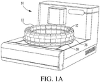
- FIG. 1a a perspective view of a histopathology apparatus which is designated generally by reference numeral 10.
- Apparatus 10 is designed to automatically stain or otherwise treat tissue mounted on microscope slides with reagents associated therewith in the desired sequence, time and temperature.
- Other devices which may use reagents in the course of processing include Immunohistochemical stainers, devices that perform in-situ hybridization on DNA/RNA, stainers that perform enzymatic tissue stains, and hemtoxylin and eosin (H & E) stainers.
- Tissue sections so stained or treated are then to be viewed under a microscope by a medical practitioner who reads the slide for purposes of patient diagnosis, prognosis, or treatment selection.
- a preferred configuration of apparatus 10, as well as system 12 is generally described in United States Patent Application Serial Number 08/909,335 (pending) filed on August 11, 1997 by inventors Druyor-Sanchez et al. , and in United States Patent Application Serial Number 08/995,052 (pending) filed on December 19, 1997 by inventors Druyor-Sanchez et al. , except with respect to the novel reagent aspirate/delivery system, as disclosed below.
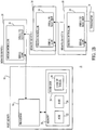
- apparatus 10 functions as one component or module in a system 11, as shown in FIG. 1b , which includes a host device 14.
- the host device 14 is a typical personal computer with a processor 16.
- the processor 16 is also in communication with memory devices 20, including non-volatile memory devices such as a ROM 22, volatile memory devices such as a RAM 24, and a hard disk 26. Any of the memory devices may contain databases or look-up tables; however, in the preferred embodiment, the hard disk 26 contains the databases or look-up tables 28.
- the remote device 10 includes a processor, such as a microcontroller 30. In an alternative embodiment, the microcontroller 30 in the remote device 10 is replaced by a personal computer.
- the microcontroller 30 is manufactured by Dallas Semiconductor, model number DS2251T 128K Soft microcontroller module.
- the microcontroller 30 has two lines (serial to PC, serial to next inst) to facilitate communication between the host and the remote devices.
- the host device 14 through the processor 16, is connected to the serial to PC pin of the microcontroller 30 of remote device 1 ( 10 ).
- the serial to next inst line of the microcontroller 30 of remote device 1 ( 10 ) is connected to the serial to PC pin of remote device 2 ( 10 ).
- the connections follow similarly through remote device N ( 10 ). In the preferred embodiment, there are up to 8 remote devices on the network.
- the serial to next instrument line is connected to a terminator 34.
- the terminator 34 can thereby match the impedance of the network.
- the serial to PC line and the serial to next remote device line need only be connected to each other for the remote device 10 to be removed from the network. Thereby, the network does not "see" that remote device 10 is effectively removed from the network.
- the remote device 10 includes a microcontroller 30.
- the microcontroller 30 has a user switch and LEDs line which connects to the status PCB (printed circuit board) 40.
- the status PCB 40 is the interface to the user for the remote device 10 and includes three LEDs (light emitting diodes) for power determination, error notification and notification of a run in progress.
- the microcontroller 30 also has a slide fan out connection which is used to control the blower fan 42.
- the blower fan 42 recirculates air to heat the slides on the slide carousel 44 of the remote device 10 by forcing air over the heater 48 and then over the slides.
- the slide temp in connection on microcontroller 30 is connected to the slide temperature monitoring sensor 46 which senses the temperature of the air.
- the slide temperature monitoring sensor 46 is positioned in the path of the heated air and thereby sends information to the microcontroller 30 when to turn the slide heater 48 on and off.
- the slide heater out connection is connected to the slide heater 48 which, as discussed previously, heats the air in order to elevate the temperature of the slides.
- the host device 14 downloads to the remote device 10 both the sequence of steps in a run program, and the sensor monitoring and control logic called the run rules.
- One of the environmental parameters is the upper and lower limit of the air temperature of the slides (used for heating the slides). If, during a run, the environmental temperature is below the lower limit, as indicated by slide temperature monitoring sensor 46, the slide heater 48 is turned on. Likewise, if the environmental temperature is above the upper limit, as indicated by slide temperature monitoring sensor 46, the slide heater 48 is turned off.
- the power supply 50 supplies both 24 VDC and 5 VDC to the applicable 24 VDC and 5 VDC connections.
- the 24 Volt power supply 50 is used to power the motors 86, 96, 126 which move the slide carousel 44 and the reagent carousel 38, and the syringe 28.
- the 120 VAC input is sent through a power switch 56, a fuse 54 and a filter 52 to the AC In connection of the power supply 50.
- the 120 VAC input is also used to power the slide heater 48, buffer heater 60 and compressor 70 of the bulk fluid module, which are described subsequently.
- the serial to PC line and the serial to next remote device line are described with reference to FIG. 1b .
- a buffer heater temperature sensor 76 is used which is physically placed on the aluminum block.
- the microcontroller 30 receives the buffer temperature sensor input via the buffer temp line and can thereby control the temperature of the buffer heater 60 by turning on and off the buffer heater 60 via the buffer heater line on the PCB microcontroller 30.
- the fluid valves 78 for the Liquid CoverslipTM and the wash buffer are controlled by the fluid valve connections. There is a separate pair of wires (power and ground) for each valve 78 shown in FIG. 1c which are omitted for ease of display. Each valve 78 is a relay which is activated by the microcontroller 30. Further, there is a slide door optical sensor 80 which is input to the slide door switch in line connection and which is used to determine if the front door of the remote device 10 is open. This sensor 80 is used for safety reasons so that, if the front door is open and remains open for five minutes, the slide carousel 44 does not move.
- Motors 86, 96 move the slide carousel 44 and the reagent carousel 38, and are connected to the slide motor out connection and the reagent motor out connection, respectively.
- the motors 86, 96 are typically stepper motors.
- Sensors 88, 98 are placed in proximity to the slide carousel 44 and the reagent carousel 38 in order to determine the "home" position of each.
- the slide carousel home sensor 86 is inductive-type and senses a piece of metal placed underneath the slide designated as the "home” position. When the "home" position is found, the sensor 88 sends a signal to the slide home in line of the microcontroller 30.
- the senor 96 also is an inductive-type of sensor.
- the reagent tray 36 has a large flat metal ring around the entire tray except for the home position. In this manner, when the sensor 96 senses an absence of metal, this is determined to be the home position thereby indicating to the microcontroller 30, via the reagent home in connection, that the home position is found.
- the sensor 96 senses the reagent tray 36, rather than the reagent carousel 38, since the user may remove the reagent tray 36. Additionally, since the sensor 96 looks for the absence of metal for the home position, the absence of the reagent tray 36 may be tested by looking for the absence of metal in two consecutive positions.
- System pressure is determined via the system air line which directly feeds into a transducer.
- the bulk fluid module 75 includes the compressor 70 which pressurizes the air to up to 620 kPa (90 psi.)
- the compressed air is sent to a filter 72 in order to filter out water and other contaminants.
- Pressure is regulated in a two-step fashion. First, the pressure is regulated at the compressor to approximately 170 kPa ⁇ 7 kPa (25 psi ( ⁇ 1psi))via a spring diaphram (prv) 68.
- the prv 68 is manufactured by Norgren in Littleton, Colorado, part number NIP-702 with a plastic bonnet.
- the pressure is fine-tuned to 90 kPa (13 psi) using an air pressure regulator 74.
- the pressure regulator 74 is very accurate in terms of precise pressure regulation over long periods of time. In this manner, the compressor 70 need not overwork itself since the prv 68 maintains the pressure at the output of the compressor to 170 kPa (25 psi)by opening and letting out excess pressure when the pressure exceeds 170 kPa (25 psi.) Water and particulates, which are filtered out of the air via the filter 72, are sent to a waste receptacle.
- the compressed air pressurizes the Liquid CoverslipTM and wash buffer bottles 64, 62 so that when the valves 78 are opened corresponding to the Liquid CoverslipTM, volume adjust, dual rinse top, dual rinse bottom lines, the pressure is already on the line and the fluid may flow.
- the compressed air is used for the dispense cylinder extend line, the dispense cylinder retract line, the mirror air cylinder line, the vortex mixers line, and the bar code blowoff/airknife line.
- the compressed air is also used for the probe out air valve 104, probe in air valve 106, and probe air down valve 108, as described subsequently.
- the mirror air cylinder line is used to turn the mirror cylinder 90 so that the bar code reader 94 either reads bar codes on the slides of the slide carousel 44 or bar codes on the fluid dispensers on the reagent carousel 38.
- the output from the bar code reader 94 is input to the microcontroller 30 via the bar code serial I/O connection.
- a flow restrictor 84 In between the valve 82 for the mirror air cylinder line and the mirror cylinder is a flow restrictor 84.
- the flow restrictor 84 slows the flow of air in the line while still maintaining the 90 kPa (13 psi)pressure on the line. In this manner, this moves the mirror slower than would otherwise be done without the restrictor 84.
- the reagent dispense system includes a reagent carousel 38, reagent vials 116, reagent vial inserts 132, reagent aspirate/dispense probe 119, probe motion control components (in the form of valves 104, 106, 108, air cylinders 112, 120 and restrictors 110), a motor driven syringe pump (in the form of a motor 126 and syringe 128), and control elements (in the form of a dispense control printed circuit board 124 and microcontroller 30).
- the reagent carousel 38 is moved via a motor 96, which is controlled by the microcontroller 30 through the reagent motor out line.
- the reagent delivery system uses a syringe 128 to move reagents from reagent vials 116 to the slides 114.
- the slide which is in the reagent dispense position is slide position 2.
- Slide position 2 corresponds to the slide denoted by "2" on the slide carousel 44.
- the reagent vials 116 are standard plastic vials that are used to package reagents.
- the microcontroller 30 controls the motion of the probe 119 via control of the air cylinders by the system pressure in line.
- the microcontroller 30 also controls the cleaning of the probe 119 and probe dispense & wash station 118, as described subsequently via the dispense control pcb 124.
- the microcontroller sends control signals via the dispense control line to the dispense control pcb 124.
- the dispense control pcb 124 controls the valves 100, 102 which channel wash buffer to the probe 119 and probe dispense & wash station 118.
- the dispense control pcb 124 further controls the motor 126 which is connected to the plunger of the syringe 128.
- there is an optical sensor 130 which is activated when the syringe is in the home position.
- the probe motion control components include air cylinders 112, 120.
- the air cylinders 112, 120 produce a piston-like motion, moving the probe 119 in all necessary directions including the 'Z' and ' ⁇ ' directions.
- probe in/out air cylinder 112 in combination with probe out air valve 104 and probe in air valve 106, control the movement of the probe 119 in the horizontal direction.
- the probe out air valve 104 and the probe in air valve 106 are pressurized using air at 90 kPa (13 psi.)
- the outputs of the probe out air valve 104 and the probe in air valve 106 are connected to flow restrictors 110, which are in turn connected to the probe in/out air cylinder 112.
- the microcontroller 30 controls the opening and closing of the probe out air valve 104 and the probe in air valve 106 so that movement of the probe 119 in the horizontal direction may be controlled.
- flow restrictors 110 are used to control the flow of pressurized air from the valves 104, 106 to the probe in/out air cylinder 112.
- the probe in/out air cylinder 112 may move the probe 119 from above the probe dispense & wash station 118 and the reagent vial 116.
- movement in the 'Z' direction is controlled by the probe down air valve 108 in combination with the probe air cylinder with spring return 120.
- Air pressurized at 90 kPa (13 psi) is connected to the probe down air valve 108.
- the output of the probe down air valve 108 is connected to the probe air cylinder with spring return 120.
- the microcontroller 30 controls the opening and closing of the probe down air valve 108 so that, upon activation of the probe down air valve 108, the probe air dispense cylinder 120 pushes the probe 119 downward. Therefore, upon closing of the probe down air valve 108, the probe air cylinder 120 is retracted by the spring return.
- the probe 119 is in the dispense position when the probe 119 is inserted into the probe dispense & wash station 118, as described subsequently. Moreover, the probe 119 is in the aspirate position when the probe 119 is inserted into the vial insert 132, also described subsequently. Therefore, a variety of air cylinders may be used including air cylinders to push in and push out and air cylinders in combination with spring return. In an alternate embodiment, the probe may be moved by using a variety of force mechanisms such as a motor, solenoid or a piston.
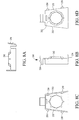
- the syringe 128 aspirates and dispenses reagent via a motor 126, as shown in Figure 2 .
- the syringe is manufactured by Hamilton Corporation, Model Gastight and whose plunger 129 is connected to a lead screw 126 which is rotated by a stepping motor.
- Tubing 142 is also connected to the probe, as described subsequently.
- the microcontroller 30 also controls the stepping motor and lead screw so that when the probe 119 is in the dispense position ( i.e., inserted into the probe dispense & wash station 118), the stepping motor and lead screw drive 126 the plunger 129 of the syringe 128 to force reagent from the syringe 128 and from the tubing 142 into the probe dispense & wash station 118, through additional tubing 170 and onto the microscope slide 114.
- the syringe may be driven to aspirate or dispense reagent through a variety of methods including air cylinders, solenoids or any other means to move the plunger of the syringe.
- the probe is, in a preferred embodiment, a cylindrical object made of stainless-steel with one end being a shaped surface. In a preferred embodiment, the one end is curved in the form of a hemisphere.
- the vial insert 132 is composed of a pliable material such as SANTOPRENETM.
- the probe and the vial insert may be composed of any substances which form a seal, as described subsequently, when the vial insert 132 and the probe 119 contact.
- one or both of the probe and the vial insert may be composed of a soft, pliable material.
- the probe may be composed of a rubber-type of material and the vial insert may be composed, in part, of stainless-steel.
- the probe 119 is milled at one portion so that an o-ring 134 may be snapped into the milled portion of the probe 119.
- the o-ring 134 is composed of a pliable material such as KALREZTM by Dupont.
- KALREZTM a pliable material
- the probe 119 and vial insert 132 contact each other to form a seal. So that, the probe may be any form with one end that forms a seal between at least a portion of one surface of the probe 119 and at least one portion of the vial insert 132.
- the seal formed is annular.
- the probe further has a hollow portion 140 for receiving the tubing 142 to the syringe 128. In a preferred embodiment, the tubing is threaded to a hole 144 at one end of the probe 119.
- FIGS. 4a-f there is shown a top view, a cross-sectional view at section A-A, a left side view, a right side view, a cross-sectional view at section B-B and bottom view of the vial insert 132 as shown in FIG. 3 .
- the vial insert 132 is pressed into the top portion of the reagent vial with ribs, that are formed around the circumference or outer surface of the vial insert 132, deforming in order to tightly fit the vial insert 132 in the opening of the reagent vial 116.
- the top portion of the vial insert has a seat 148 with abuts against the top portion of the reagent vial.
- the vial insert 132 also has an upper surface 150 which is shaped.
- the upper surface is a curved surface that is funnel-like.
- a portion of the upper surface 150 mates with at least a part of the lower portion of the probe.
- the upper surface of the vial insert contacts the portion on the probe below the o-ring, as shown in Figure 3 .
- a portion of the funnel-like curved surface may engage any portion of the probe, including the o-ring.
- the conical shape of the upper surface of the vial insert in contact with the lower spherical-shaped portion of the probe forms a cavity 152.
- the cavity 152 in a preferred embodiment is funnel-shaped so that any reagent left in the vial insert 132 will flow back down into the vial 116 when the probe is removed.
- the upper surface is a curved surface that is hemispherical, so that a larger percentage of the surface area of the curved end of the probe abuts the upper surface.
- the surface area of contact between the probe and the vial insert 132 should be kept to a minimum while still avoiding an air leak between the probe 119 and the vial insert 132.
- the vial insert 132 is molded so that the lowest portion of the upper surface includes a vial transition area 154.
- the vial transition area 154 in a preferred embodiment, is integral with the main body of the vial insert 132. In an alternate embodiment, the vial transition area may be composed of a separate piece which is snapped into the main body of the vial insert.
- the vial transition area 154 is adjacent to the dip tube 156, which is composed of Teflon ® tubing and which fits in the molded lower portion of the vial insert.
- the dip tube 156 has an inner diameter and an outer diameter, which in the preferred embodiment is 1/32" and 1/16", respectively. In a preferred embodiment, the diameter of the vial transition area 154 should equal the inner diameter of the dip tube 156.
- the dip tube 156 when the dip tube 156 is inserted into the cavity 158 adjacent to the vial transition area 154, it results in a smooth transition between the vial transition area 154 and the dip tube 156. Therefore, the diameter of the vial transition area is 1/32". In this manner, reagent will not be trapped in the vial transition area 154 or in the dip tube 156. And, the small vial transition area 154 reduces evaporation of the reagent.
- the vial insert is also molded with cavities 160 in order for the vial insert to be molded with accuracy.
- the probe 119 is inserted into the vial insert 132, the plunger 129 of the syringe 128 is withdrawn and reagent is drawn from the vial 116.
- the hole 144 for the lower portion of the probe lines up with the vial transition area, as shown in Figure 3 .
- the hole 144 need not line up with the vial transition area 154. Reagent may still travel as long as a seal between the probe 119 and the vial insert 132 is maintained.
- a pathway for air to travel from outside the vial and the vial insert 132 is included.
- the pathway is formed by breaks 162 in the ribs, as shown in Figures 4c and 4d .
- the breaks 162 in the ribs are formed for the air to travel in a circuitous path around the vial insert 132. In this manner, the pathway allows for the equalization of pressure while still minimizing spillage, if the reagent vial is tipped over, due to the circuitous path.
- Other pathways may include spirals or helixes.
- FIG. 5 is a front cross-sectional view of the a probe 119 and probe dispense & wash station 118 for the reagent delivery system of FIG. 2 .
- the probe dispense & wash station 118 has an upper surface 168, as described subsequently, wherein at least a portion of the upper surface 168 engages at least a portion of the probe 119 to form a seal. This seal allows for the dispensing of reagent from the tubing 142 to the probe dispense & wash station 118.
- the probe 119 and the probe dispense & wash station 118 may be composed of any substances which enable a seal to form when the probe dispense & wash station 118 and the probe 119 contact.
- both the probe 119 and the probe dispense & wash station 118 may be composed of a plastic or rubberized material.
- the probe dispense & wash station 118 is composed of stainless steel.
- the point of contact is between the o-ring 134 and a portion of the upper surface 168 of the probe dispense & wash station, as shown in Figure 5 .
- the upper surface 168 of the probe dispense & wash station may be any shape as long as a seal is formed between the probe 119 and the probe dispense & wash station 118.
- the upper surface 168 of the probe dispense & wash station 118 should mate with the lower portion of the probe 166 to form an annular seal. Since the lower portion of the probe 166 is spherical in shape, the upper surface 168 of the probe dispense & wash station is also spherical in shape. In practice, the diameter of the upper surface 168 is slightly larger than the diameter of the curved lower portion 166 of the probe.
- the point of contact between the probe 119 and the probe dispense & wash station 118 in the preferred embodiment is between a portion of the upper surface and the o-ring 134 that forms the annular seal. And, to minimize reagent left in the probe dispense & wash station, the volume between the upper surface 168 of the probe dispense & wash station and the lower portion 166 of the probe is kept to a minimum.
- the hole 144 for the lower portion of the probe lines up with the hole 174 in the upper surface 168 of the probe dispense & wash station 118.
- the hole need not line up with the hole in the upper surface of the probe dispense & wash station 118. Reagent may still travel as long as a seal between the probe 119 and the probe dispense & wash station 118 is maintained.
- the lower portion of the probe dispense & wash station includes a screw fitting 170 for holding the Teflon ® tubing 170.
- a trough 172 formed within the probe dispense & wash station 118.
- the trough 172 acts to catch reagent, which spirals downward and empties outside of the probe dispense & wash station 118.
- a probe wash fitting 176 holds tubing 180 which is connected, via a hole 178, to the upper surface 168 of the probe dispense & wash station 118.
- the hole may be placed at any portion of the upper surface 168 of the probe dispense & wash station 118.
- the hole 178 is placed between the juncture at o-ring 134 and the hole 174 to the tubing, as shown in Figure 5 .
- FIG. 6 is a perspective view of the air cylinders for the reagent delivery system of FIG. 2 . Due to the need to avoid placing reagent into the plunger 129 of the syringe, the tubing 142 is of sufficient length so that any reagent will be contained within the tubing 142.
- reagents may be used.
- the vial inserts and the samples on the microscopes the probe and probe dispense & wash station 118 should be cleaned after dispensing of a reagent.
- wash buffer is used to clean the probe 119 and the probe dispense & wash station 118.
- a probe purge liquid valve 102 and a probe wash liquid valve 100 both pressurized with wash buffer at 90 kPa (13 psi), are connected to the probe 119 and the probe dispense & wash station 118, respectively.
- a flow restrictor 122 limits the flow of wash buffer from the probe wash liquid valve and the probe dispense & wash station 118.
- the dispense control pcb 124 in combination with the microcontroller 30, controls the operation of the probe purge liquid valve 102 and the probe wash liquid valve 100.
- the carrousel 44 is advanced so that the probe 119 and probe dispense & wash station 118 are in between slides.
- the dispense control pcb 124 in combination with the microcontroller 30, turns on the probe purge liquid valve 102 and the probe wash liquid valve 100 so that both the probe 119 and the probe dispense & wash station 118 are rinsed with wash buffer.
- the wash buffer is deposited into the waste tub 58 instead of onto the slides in the carrousel 44.
- the probe 119 and the probe dispense & wash station 118 are cleaned when the probe 119 is inserted in the probe dispense & wash station 118.
- the dispense control pcb 124 in combination with the microcontroller 30, alternates turning one valve on and then off, and then turning the other valve on and then off. For example, the dispense control pcb 124 turns on the probe purge liquid valve 102, waits a predetermined amount of time, as described subsequently, and then turns off the probe purge liquid valve 102.
- the dispense control pcb 124 in combination with the microcontroller 30, turns on the probe wash liquid valve 100, waits a predetermined amount of time, as described subsequently, and then turns off the probe wash liquid valve 100.
- the dispense control pcb 124 may begin the cleaning by turning on the probe wash liquid valve 100 first. This alternating of the flow of wash buffer from the probe purge liquid valve 102 and the probe wash liquid valve 100 produces a scrubbing action which cleans the probe 119 and the probe dispense & wash station 118 more effectively.
- the probe purge liquid valve 102 and the probe wash liquid valve 100 may be turned on simultaneously in order to clean the probe 119 and the probe dispense & wash station 118.
- the instrument reagent carousel 38 rotates to position the reagent tray so that the required reagent vial is positioned beneath the reagent probe 119; the probe 119 is then inserted into the vial insert 132 and reagent is aspirated into tubing 142 above the probe by drawing liquid into the syringe 128; the probe 119 is then raised and rotated to a position above the probe dispense & wash station 118; the probe 119 is then lowered in the probe dispense & wash station 118; the probe dispense & wash station 118 is connected to a piece of tubing 170 which is routed within the instrument such that the exit end of the tubing 170 is just above the microscope slide 114; when the probe 119 is down and seated into the probe dispense & wash station 118, the syringe pump 129 is reversed and the reagent is dispensed onto the microscope slide 114.
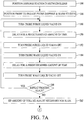
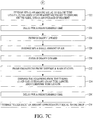
- Blocks 186-200 relate to the steps for washing the probe and the probe dispense & wash station 118. Simultaneously with the wash probe macro, the reagent tray is moved in anticipation of obtaining the particular reagent.
- the dispense station is positioned in between slides. In a preferred embodiment, the slide is indexed by 1/2 of a position. This is so that any wash buffer which is used to clean the probe and the probe dispense & wash station 118 falls into the waste tub instead of onto one of the slides.
- the probe is placed in the proper position to engage the probe dispense & wash station 118 (i.e., the probe down air valve 108 and the probe in air valve 106 are activated).
- the probe purge liquid valve is turned on, thereby sending wash buffer through the tubing to the probe.
- a delay block is entered for a predetermined amount of time (in a preferred embodiment for 2 seconds).
- the probe purge liquid valve is turned off, thereby stopping wash buffer through the tubing to the probe.
- the probe wash liquid valve is turned on, thereby sending wash buffer through the tubing to the probe dispense & wash station 118.
- a delay block is entered for a predetermined amount of time (in a preferred embodiment for 1 second).
- the probe wash liquid valve is turned off, thereby stopping wash buffer through the tubing to the probe dispense & wash station 118.
- the second sequence of alternating washing includes the steps of turning on the probe purge liquid valve, delaying for .59 seconds, and then turning off the probe purge liquid valve. Thereafter, the probe wash liquid valve is turned on, delayed for .50 seconds, and then turned off.
- This alternating of the activation of the probe purge liquid valve and the probe wash liquid valve allows for a scrubbing action, thereby cleaning the probe and the probe dispense & wash station 118 more effectively. Also, the delay times in between activation of the valves is decreased during the sequence of washings. Moreover, this alternating action may be for two cycles, as disclosed in Figure 3 , or may be for any number of cycles, depending on time constraints. Further, in the preferred embodiment, the alternating action begins with turning on the probe purge liquid valve. In an alternate embodiment, the alternating action may begin with turning on the probe wash liquid valve.
- the amount of volume adjust necessary for the slide is sipped by the syringe.
- a certain amount of wash buffer is necessary in order to process the sample.
- the wash buffer may be introduced to the sample in a variety of ways, one of which is through a syringe.
- the dispense station is positioned over the slide. In a preferred embodiment, the slide position is indexed by 1/2 of a position. This is so that the probe dispense & wash station 118 is positioned properly over the slide.
- the volume adjust obtained at block 202 is dispensed onto the slide. This is accomplished by the processor turning on the motor to push the plunger of the syringe.
- the syringe sips an amount equal to the dispense tube length, which is the tubing that directs fluid from the probe dispense & wash station 118 onto the slide. This is performed by turning on the motor to pull the plunger of the syringe and is done in order to avoid dripping onto the slide.
- the reagent tray is moved to the required position in order to obtain the particular reagent.
- the probe is placed in its up position.
- the syringe sips the blow down length of the dip tube.
- the reagent vial 116 has a dip tube 156 inside of it. Due to different levels of reagent in different reagent vials, the dip tube may be filled to different amounts. In order to consistently draw reagent from each reagent vial, air is forced into the syringe with an amount at least equal to the internal volume of the dip tube. As shown in Figure 3 , the dip tube has a predetermined internal volume.
- each reagent vial begins with a dip tube filled with air, regardless of whether the reagent vial is full or almost empty, so that a consistent amount of reagent may be drawn.
- the syringe may sip an amount less than the blow down length of the dip tube; however, the amount should be sufficient such that, for any reagent vial either filled or nearly empty with reagent, the dip tube should be filled with air after the air is forced into the dip tube.
- the top of the dip tube is above the portion of the reagent vial which would contain reagent.
- a volume of air need only be forced into the dip tube for the portion of the dip tube which is below the fill line of the reagent vial.
- the probe engages the vial insert, by turning on the probe out air valve 104 and by turning on the probe down air valve 108. At this point, the probe is engaged with the vial insert for the particular reagent, as described subsequently.
- the vial blow down length is spit out of the syringe in order to fill the dip tube with air, as discussed previously.
- the system delays for a predetermined amount of time (in a preferred embodiment for .15 seconds). This delay allows the system equilibrate itself. Because of the use of plastics in the system (such as the reagent vial), the system has a certain amount of elasticity. In order to avoid inaccuracies, the process is delayed in order for the system to settle.
- the syringe sips (1) an amount equal to the dip tube length (which is air due to dip tube being previously evacuated), (2) the amount of reagent necessary to dispense on the slide, and (3) an overage of reagent. Sipping overage is necessary due to dilution of the reagent in the tubing. Due to using wash buffer in previous cycles, residual wash buffer is still in the tubing of the syringe since as wash buffer is pulled out, residual wash buffer remains. This residual wash buffer in the tubing dilutes the reagent which is sipped into the tubing. Therefore, an overage of reagent equal to 10% is sipped.
- the system delays for a predetermined amount of time (in a preferred embodiment 1 second) in order for the system to equalize and the reagent to settle in the tubing of the syringe.
- the probe disengages the vial insert when the probe is drawn upward.
- the motor for the syringe sips a small amount of air, as shown at block 228. This is due to the fact that upon drawing the probe upward, a droplet of reagent may be at the end of the probe. In order to avoid contamination of the slides, the droplet is sipped upward.
- the probe is drawn inward by activation of the probe in air valve 106.
- the reagent is dispensed.
- the probe engages the probe dispense & wash station by placed the probe downward into the probe dispense & wash station 118.
- the motor for the syringe is activated so that the following amounts may be dispensed: (1) air gap (which was sipped up at block 222 in order to remove droplet at the end of the probe); (2) reagent (which was sipped up at block 222; note that the overage is not dispensed); (3) dip tube length; and (4) dispense tube length (which is the tube between the probe dispense & wash station 118 and the slide).
- the syringe "sucks back" an amount approximately equal to one drop (e.g. , 25 ⁇ L). This is due to the fact that a droplet may be at the end of the tubing 170 above the slide. And, when the probe dispense & wash station 118 moves, along with the tubing 170, the droplet above the tubing may drop onto another slide. This "suck back," which withdraws the droplet, therefore allows for more accurate and more consistent dispensing of reagents.
- FIG. 8a-d there is shown a cross section, side, bottom, and top view of the reagent holder.
- a flat surface 254 for affixing a barcode flag.
- a U-shaped member 256 which abuts against the reagent tray 36, as shown in Figure 1a , thereby keeping the reagent vial and the barcode flag in a fixed position.
- a locking tab which abuts the U-shaped member which keeps the reagent vial from moving upward. In this manner, the reagent vial and barcode flag is kept in a fixed position.
- the reagent vial In order to maintain a proper position of the reagent vial in the reagent carousel 38, the reagent vial should be fixed in position.
- a collar 242 as part of the reagent holder 240, holds the reagent vial in place.
- the neck 246 of the reagent vial is pushed through the collar 242, as shown in Figure 3 , to form a snap fit, so that a ledge 248 abuts the top of the collar 242.
- the reagent holder has interlocking tabs 250 so that separate reagent vials may be attached together.
- the reagent vials when attached by the interlocking tabs 250, form a curve, which follows the curve of the reagent tray 36.
- a series of reagent vials 116, interlocked with the reagent holders 240, may be placed directly on the reagent tray 36.
Landscapes
- Health & Medical Sciences (AREA)
- Life Sciences & Earth Sciences (AREA)
- General Physics & Mathematics (AREA)
- Immunology (AREA)
- Pathology (AREA)
- Physics & Mathematics (AREA)
- Chemical & Material Sciences (AREA)
- Analytical Chemistry (AREA)
- Biochemistry (AREA)
- General Health & Medical Sciences (AREA)
- Engineering & Computer Science (AREA)
- Biomedical Technology (AREA)
- Molecular Biology (AREA)
- Sampling And Sample Adjustment (AREA)
- Automatic Analysis And Handling Materials Therefor (AREA)
- Apparatus Associated With Microorganisms And Enzymes (AREA)
- Investigating Or Analysing Biological Materials (AREA)
- Microscoopes, Condenser (AREA)
- Devices For Use In Laboratory Experiments (AREA)
- Laminated Bodies (AREA)
- Measuring Or Testing Involving Enzymes Or Micro-Organisms (AREA)
Abstract
Description
- This invention relates generally to the fields of histology and cytology, and more particularly relates to a method and apparatus for aspirating and dispensing reagent.
- Reagents are used in a variety of devices in the fields of histology and cytology. For example, one device which uses reagents is a histochemical staining device. Histochemical staining is a useful tool in histological diagnosis and the study of tissue morphology. Histochemical "Special Stains" require a series of treatment steps conducted on a tissue section mounted on a glass slide to highlight by selective staining certain morphological indicators of disease states. Typical steps may include pretreatment of the tissue section to facilitate staining, application of various dyes to stain morphological structures, clarifiers to remove unreacted dye, differentiating agents, counterstains, and the like. Each of these steps is separated by multiple rinse steps to remove unreacted residual reagent from the prior step. Incubations are conducted at elevated temperatures, usually around 60°C, and the tissue must be continuously protected from dehydration. Other devices that use reagents as part of its processing include Immunohistochemical stainers, devices that perform in-situ hybridization of DNA/RNA, stainers that perform enzymatic tissue stains, and hemtoxylin and eosin (H & E) stainers.
- In order to introduce reagents and other fluids during processing, a reagent delivery system and method is used. Typically, the reagent delivery system automatically pipettes reagents by inserting a needle or plastic tube into the reagent reservoir or vial, drawing up the reagent into the tube with a motor driven syringe, moving the needle to the slide (or other receptacle) and reversing the syringe to dispense the reagent. Such typical designs have the drawback that the vials are open, exposing the reagent to the atmosphere, permitting evaporation and potentially reducing reagent reactivity due to oxygen exposure. Moreover, open vials are vulnerable to spills resulting in loss of reagent and operator exposure.
US4974459A discloses a procedure for implementing selection of liquids in liquid dispensing in an analyzer, and sampling device.US5597733A discloses an automatic multiple-sample multiple-reagent dispensing method in chemical analyzers.US4888998A discloses a sample handling system including a sample injection cell having an open chamber.EP0602802A1 discloses probe washing apparatus including a probe having a tip and a wash collar having a bore coaxially aligned with the probe.EP0701865A1 discloses a spotting tip including a tip body fitted on the end of a nozzle for sucking liquid contained in a container when the tip is inserted into the container to a predetermined depth. - The present invention is directed to an apparatus and method for applying reagent to slides for histochemical or cytological analysis, as defined in the claims. As part of these analyses, different types of reagents are applied to tissue sections placed on slides. The tissue sections are then viewed by a medical practitioner who reads the slide for purposes of patent diagnosis, prognosis or treatment selection. More specifically, the apparatus is a staining instrument that automatically applies chemical and biological reagents to tissue or cells mounted or affixed to standard glass microscope slides. Each slide receives the selected reagents which are dispensed from reagent vials.
- Obtaining of reagents is accomplished through a unique reagent dispense system that comprises a probe, a vial insert and a reagent vial. The vial insert is attached to the reagent vial. The vial insert is also contacted with at least a portion of the probe to form a seal wherein reagent is withdrawn from the reagent vial. Dispensing of reagents is accomplished by a probe and a probe dispense and wash station. The probe contacts at least a portion of the probe dispense and wash station to form a seal in order to dispense reagent and in order to clean the probe.
- A key advantage of the present invention is to provide a system that aspirates reagents from a vial while minimizing evaporation in the reagent vial.
- Another advantage of the present invention is to provide a system that dispenses reagents accurately.
- Still another advantage of the present invention is to provide a system that minimizes cross-contamination of the reagent vials through cleaning of the reagent delivery system.
- With the foregoing and other objects, advantages, and features of the invention that will become hereinafter apparent, the nature of the invention may be more clearly understood by reference to the following detailed description of the invention, the appended claims and to the several views illustrated in the drawings.
- A presently preferred embodiment is described herein with reference to the drawings wherein:
-
FIG. 1 a is a perspective view of a biological reaction system showing a reagent carousel, reagent tray, and reagent vials; -
FIG. 1b is a block diagram of the host and reagent -
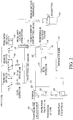
FIG. 1c is a block diagram of the biological reaction system as disclosed inFIG. 1a ; -
FIG. 2 is a diagram of the reagent delivery system as disclosed inFIGS. 1a and1b ; -
FIG. 3 is a front cross-sectional view of the probe, vial insert and reagent vial for the reagent delivery system ofFIG. 2 ; -
FIG. 4a is a top view of the vial insert as shown inFIG. 3 ; -
FIG. 4b is a cross-sectional view at section A-A ofFIG. 4a ; -
FIG. 4c is a left side view of the vial insert as shown inFIG. 3 ; -
FIG. 4d is a right side view of the vial insert as shown inFIG. 3 ; -
FIG. 4e is a cross-sectional view at section B-B ofFIG. 4d ; -
FIG. 4f is a bottom view of the vial insert as shown inFIG. 3 ; -
FIG. 5 is a front cross-sectional view of the a probe and probe dispense & wash station for the reagent delivery system ofFIG. 2 ; -
FIG. 6 is a perspective view of the air cylinders for the reagent delivery system ofFIG. 2 ; -
FIG. 7 is a flow chart of an example of the operation of the reagent delivery system ofFIG. 2 ; and -
FIGS. 8a-d is a cross section, side, bottom, and top view of the reagent holder as shown inFIG. 3 . - Referring now in detail to the drawings wherein like parts are designated by like reference numerals throughout, there is illustrated in
FIG. 1a a perspective view of a histopathology apparatus which is designated generally byreference numeral 10. This is merely one example of a device which uses reagents during processing.Apparatus 10 is designed to automatically stain or otherwise treat tissue mounted on microscope slides with reagents associated therewith in the desired sequence, time and temperature. Other devices which may use reagents in the course of processing include Immunohistochemical stainers, devices that perform in-situ hybridization on DNA/RNA, stainers that perform enzymatic tissue stains, and hemtoxylin and eosin (H & E) stainers. Tissue sections so stained or treated are then to be viewed under a microscope by a medical practitioner who reads the slide for purposes of patient diagnosis, prognosis, or treatment selection. A preferred configuration ofapparatus 10, as well assystem 12, is generally described in United States Patent Application Serial Number08/909,335 (pending) filed on August 11, 1997 by inventors Druyor-Sanchez et al. , and in United States Patent Application Serial Number08/995,052 (pending) filed on December 19, 1997 by inventors Druyor-Sanchez et al. , except with respect to the novel reagent aspirate/delivery system, as disclosed below. - In a preferred embodiment,
apparatus 10 functions as one component or module in asystem 11, as shown inFIG. 1b , which includes ahost device 14. Thehost device 14 is a typical personal computer with aprocessor 16. Theprocessor 16 is also in communication withmemory devices 20, including non-volatile memory devices such as a ROM 22, volatile memory devices such as aRAM 24, and ahard disk 26. Any of the memory devices may contain databases or look-up tables; however, in the preferred embodiment, thehard disk 26 contains the databases or look-up tables 28. Theremote device 10 includes a processor, such as amicrocontroller 30. In an alternative embodiment, themicrocontroller 30 in theremote device 10 is replaced by a personal computer. Themicrocontroller 30 is manufactured by Dallas Semiconductor, model number DS2251T 128K Soft microcontroller module. Themicrocontroller 30 has two lines (serial to PC, serial to next inst) to facilitate communication between the host and the remote devices. As shown inFIG. 1b , thehost device 14, through theprocessor 16, is connected to the serial to PC pin of themicrocontroller 30 of remote device 1 (10). The serial to next inst line of themicrocontroller 30 of remote device 1 (10) is connected to the serial to PC pin of remote device 2 (10). The connections follow similarly through remote device N (10). In the preferred embodiment, there are up to 8 remote devices on the network. In order to terminate the network with the correct impedance in order to avoid any pulse reflections on the network, the serial to next instrument line is connected to aterminator 34. Theterminator 34 can thereby match the impedance of the network. In the event that one of the remote devices on the network must be removed from the network, the serial to PC line and the serial to next remote device line need only be connected to each other for theremote device 10 to be removed from the network. Thereby, the network does not "see" thatremote device 10 is effectively removed from the network. - Referring to
Figure 1c , there is shown an expanded block diagram of the remote device as disclosed inFIG. 1a . As discussed previously, theremote device 10 includes amicrocontroller 30. Themicrocontroller 30 has a user switch and LEDs line which connects to the status PCB (printed circuit board) 40. Thestatus PCB 40 is the interface to the user for theremote device 10 and includes three LEDs (light emitting diodes) for power determination, error notification and notification of a run in progress. - The
microcontroller 30 also has a slide fan out connection which is used to control theblower fan 42. Theblower fan 42 recirculates air to heat the slides on theslide carousel 44 of theremote device 10 by forcing air over theheater 48 and then over the slides. The slide temp in connection onmicrocontroller 30 is connected to the slide temperature monitoring sensor 46 which senses the temperature of the air. The slide temperature monitoring sensor 46 is positioned in the path of the heated air and thereby sends information to themicrocontroller 30 when to turn theslide heater 48 on and off. The slide heater out connection is connected to theslide heater 48 which, as discussed previously, heats the air in order to elevate the temperature of the slides. Thehost device 14 downloads to theremote device 10 both the sequence of steps in a run program, and the sensor monitoring and control logic called the run rules. One of the environmental parameters is the upper and lower limit of the air temperature of the slides (used for heating the slides). If, during a run, the environmental temperature is below the lower limit, as indicated by slide temperature monitoring sensor 46, theslide heater 48 is turned on. Likewise, if the environmental temperature is above the upper limit, as indicated by slide temperature monitoring sensor 46, theslide heater 48 is turned off. Thepower supply 50 supplies both 24 VDC and 5 VDC to the applicable 24 VDC and 5 VDC connections. The 24Volt power supply 50 is used to power themotors slide carousel 44 and thereagent carousel 38, and thesyringe 28. The 120 VAC input is sent through apower switch 56, a fuse 54 and afilter 52 to the AC In connection of thepower supply 50. The 120 VAC input is also used to power theslide heater 48,buffer heater 60 andcompressor 70 of the bulk fluid module, which are described subsequently. The serial to PC line and the serial to next remote device line are described with reference toFIG. 1b . - In order to control the temperature of the block, a buffer heater temperature sensor 76 is used which is physically placed on the aluminum block. The
microcontroller 30 receives the buffer temperature sensor input via the buffer temp line and can thereby control the temperature of thebuffer heater 60 by turning on and off thebuffer heater 60 via the buffer heater line on thePCB microcontroller 30. - The
fluid valves 78 for the Liquid Coverslip™ and the wash buffer are controlled by the fluid valve connections. There is a separate pair of wires (power and ground) for eachvalve 78 shown inFIG. 1c which are omitted for ease of display. Eachvalve 78 is a relay which is activated by themicrocontroller 30. Further, there is a slide dooroptical sensor 80 which is input to the slide door switch in line connection and which is used to determine if the front door of theremote device 10 is open. Thissensor 80 is used for safety reasons so that, if the front door is open and remains open for five minutes, theslide carousel 44 does not move. -
Motors slide carousel 44 and thereagent carousel 38, and are connected to the slide motor out connection and the reagent motor out connection, respectively. Themotors Sensors slide carousel 44 and thereagent carousel 38 in order to determine the "home" position of each. In the case of theslide carousel 44, the slidecarousel home sensor 86 is inductive-type and senses a piece of metal placed underneath the slide designated as the "home" position. When the "home" position is found, thesensor 88 sends a signal to the slide home in line of themicrocontroller 30. In the case of thereagent tray 36, thesensor 96 also is an inductive-type of sensor. Thereagent tray 36 has a large flat metal ring around the entire tray except for the home position. In this manner, when thesensor 96 senses an absence of metal, this is determined to be the home position thereby indicating to themicrocontroller 30, via the reagent home in connection, that the home position is found. Thesensor 96 senses thereagent tray 36, rather than thereagent carousel 38, since the user may remove thereagent tray 36. Additionally, since thesensor 96 looks for the absence of metal for the home position, the absence of thereagent tray 36 may be tested by looking for the absence of metal in two consecutive positions. - System pressure is determined via the system air line which directly feeds into a transducer. As shown in
FIG. 1c , the bulk fluid module 75 includes thecompressor 70 which pressurizes the air to up to 620 kPa (90 psi.) The compressed air is sent to a filter 72 in order to filter out water and other contaminants. Pressure is regulated in a two-step fashion. First, the pressure is regulated at the compressor to approximately 170 kPa ± 7 kPa (25 psi (± 1psi))via a spring diaphram (prv) 68. Theprv 68 is manufactured by Norgren in Littleton, Colorado, part number NIP-702 with a plastic bonnet. Second, the pressure is fine-tuned to 90 kPa (13 psi) using anair pressure regulator 74. Thepressure regulator 74 is very accurate in terms of precise pressure regulation over long periods of time. In this manner, thecompressor 70 need not overwork itself since theprv 68 maintains the pressure at the output of the compressor to 170 kPa (25 psi)by opening and letting out excess pressure when the pressure exceeds 170 kPa (25 psi.) Water and particulates, which are filtered out of the air via the filter 72, are sent to a waste receptacle. The compressed air pressurizes the Liquid Coverslip™ and washbuffer bottles 64, 62 so that when thevalves 78 are opened corresponding to the Liquid Coverslip™, volume adjust, dual rinse top, dual rinse bottom lines, the pressure is already on the line and the fluid may flow. The compressed air is used for the dispense cylinder extend line, the dispense cylinder retract line, the mirror air cylinder line, the vortex mixers line, and the bar code blowoff/airknife line. The compressed air is also used for the probe outair valve 104, probe inair valve 106, and probe air downvalve 108, as described subsequently. - The mirror air cylinder line is used to turn the mirror cylinder 90 so that the bar code reader 94 either reads bar codes on the slides of the
slide carousel 44 or bar codes on the fluid dispensers on thereagent carousel 38. The output from the bar code reader 94 is input to themicrocontroller 30 via the bar code serial I/O connection. In between thevalve 82 for the mirror air cylinder line and the mirror cylinder is aflow restrictor 84. The flow restrictor 84 slows the flow of air in the line while still maintaining the 90 kPa (13 psi)pressure on the line. In this manner, this moves the mirror slower than would otherwise be done without therestrictor 84. - As shown in
Figure 1c and in more detail inFigure 2 , the reagent dispense system includes areagent carousel 38,reagent vials 116, reagent vial inserts 132, reagent aspirate/dispenseprobe 119, probe motion control components (in the form ofvalves air cylinders motor 126 and syringe 128), and control elements (in the form of a dispense control printedcircuit board 124 and microcontroller 30). Thereagent carousel 38 is moved via amotor 96, which is controlled by themicrocontroller 30 through the reagent motor out line. The reagent delivery system uses asyringe 128 to move reagents fromreagent vials 116 to theslides 114. As shown inFigure 1c , the slide which is in the reagent dispense position isslide position 2.Slide position 2 corresponds to the slide denoted by "2" on theslide carousel 44. Thereagent vials 116 are standard plastic vials that are used to package reagents. Themicrocontroller 30 controls the motion of theprobe 119 via control of the air cylinders by the system pressure in line. Themicrocontroller 30 also controls the cleaning of theprobe 119 and probe dispense & washstation 118, as described subsequently via the dispensecontrol pcb 124. The microcontroller sends control signals via the dispense control line to the dispensecontrol pcb 124. The dispensecontrol pcb 124 controls thevalves probe 119 and probe dispense & washstation 118. The dispensecontrol pcb 124 further controls themotor 126 which is connected to the plunger of thesyringe 128. In order for the dispensecontrol pcb 124 to determine the position of thesyringe 128, there is an optical sensor 130 which is activated when the syringe is in the home position. - In a preferred embodiment, the probe motion control components include
air cylinders air cylinders probe 119 in all necessary directions including the 'Z' and 'θ' directions. For example, probe in/outair cylinder 112, in combination with probe outair valve 104 and probe inair valve 106, control the movement of theprobe 119 in the horizontal direction. The probe outair valve 104 and the probe inair valve 106 are pressurized using air at 90 kPa (13 psi.) The outputs of the probe outair valve 104 and the probe inair valve 106 are connected to flowrestrictors 110, which are in turn connected to the probe in/outair cylinder 112. Themicrocontroller 30 controls the opening and closing of the probe outair valve 104 and the probe inair valve 106 so that movement of theprobe 119 in the horizontal direction may be controlled. In addition,flow restrictors 110 are used to control the flow of pressurized air from thevalves air cylinder 112. In practice, the probe in/outair cylinder 112 may move theprobe 119 from above the probe dispense & washstation 118 and thereagent vial 116. - In addition, movement in the 'Z' direction is controlled by the probe down
air valve 108 in combination with the probe air cylinder withspring return 120. Air pressurized at 90 kPa (13 psi)is connected to the probe downair valve 108. The output of the probe downair valve 108 is connected to the probe air cylinder withspring return 120. Themicrocontroller 30 controls the opening and closing of the probe downair valve 108 so that, upon activation of the probe downair valve 108, the probe air dispensecylinder 120 pushes theprobe 119 downward. Therefore, upon closing of the probe downair valve 108, theprobe air cylinder 120 is retracted by the spring return. - In practice, the
probe 119 is in the dispense position when theprobe 119 is inserted into the probe dispense & washstation 118, as described subsequently. Moreover, theprobe 119 is in the aspirate position when theprobe 119 is inserted into thevial insert 132, also described subsequently. Therefore, a variety of air cylinders may be used including air cylinders to push in and push out and air cylinders in combination with spring return. In an alternate embodiment, the probe may be moved by using a variety of force mechanisms such as a motor, solenoid or a piston. - The
syringe 128 aspirates and dispenses reagent via amotor 126, as shown inFigure 2 . The syringe is manufactured by Hamilton Corporation, Model Gastight and whoseplunger 129 is connected to alead screw 126 which is rotated by a stepping motor.Tubing 142 is also connected to the probe, as described subsequently. Themicrocontroller 30, via the dispensecontrol pcb 124, controls the stepping motor andlead screw 126 so that when theprobe 119 is in the aspirate position (i.e., inserted into the vial insert 132), the stepping motor andlead screw 126 drive theplunger 129 of thesyringe 128 to withdraw reagent from thereagent vial 116. Themicrocontroller 30 also controls the stepping motor and lead screw so that when theprobe 119 is in the dispense position (i.e., inserted into the probe dispense & wash station 118), the stepping motor andlead screw drive 126 theplunger 129 of thesyringe 128 to force reagent from thesyringe 128 and from thetubing 142 into the probe dispense & washstation 118, throughadditional tubing 170 and onto themicroscope slide 114. In an alternative embodiment, the syringe may be driven to aspirate or dispense reagent through a variety of methods including air cylinders, solenoids or any other means to move the plunger of the syringe. - Referring to
FIG. 3 , there is shown a front cross-sectional view of theprobe 119,vial insert 132 andreagent vial 116 for the reagent delivery system ofFIG. 2 . The probe is, in a preferred embodiment, a cylindrical object made of stainless-steel with one end being a shaped surface. In a preferred embodiment, the one end is curved in the form of a hemisphere. Thevial insert 132 is composed of a pliable material such as SANTOPRENE™. The probe and the vial insert may be composed of any substances which form a seal, as described subsequently, when thevial insert 132 and theprobe 119 contact. For example, one or both of the probe and the vial insert may be composed of a soft, pliable material. Alternatively, the probe may be composed of a rubber-type of material and the vial insert may be composed, in part, of stainless-steel. - The
probe 119 is milled at one portion so that an o-ring 134 may be snapped into the milled portion of theprobe 119. In a preferred embodiment, the o-ring 134 is composed of a pliable material such as KALREZ™ by Dupont. At both ends of the o-ring 134 are o-ring holders ring 134 in place. As described subsequently in more detail, theprobe 119 andvial insert 132 contact each other to form a seal. So that, the probe may be any form with one end that forms a seal between at least a portion of one surface of theprobe 119 and at least one portion of thevial insert 132. In a preferred embodiment, the seal formed is annular. The probe further has ahollow portion 140 for receiving thetubing 142 to thesyringe 128. In a preferred embodiment, the tubing is threaded to ahole 144 at one end of theprobe 119. - Referring to
FIGS. 4a-f , there is shown a top view, a cross-sectional view at section A-A, a left side view, a right side view, a cross-sectional view at section B-B and bottom view of thevial insert 132 as shown inFIG. 3 . Thevial insert 132 is pressed into the top portion of the reagent vial with ribs, that are formed around the circumference or outer surface of thevial insert 132, deforming in order to tightly fit thevial insert 132 in the opening of thereagent vial 116. In addition, the top portion of the vial insert has aseat 148 with abuts against the top portion of the reagent vial. Thevial insert 132 also has anupper surface 150 which is shaped. In the preferred embodiment, the upper surface is a curved surface that is funnel-like. When the probe engages thevial insert 132, a portion of theupper surface 150 mates with at least a part of the lower portion of the probe. In a preferred embodiment, the upper surface of the vial insert contacts the portion on the probe below the o-ring, as shown inFigure 3 . In an alternative embodiment, a portion of the funnel-like curved surface may engage any portion of the probe, including the o-ring. - Upon contact or engaging of the probe with the
vial insert 132, a seal is formed so that when withdrawing reagent, air does not leak from theupper surface 150 of the vial insert, as described subsequently. In a preferred embodiment, the conical shape of the upper surface of the vial insert in contact with the lower spherical-shaped portion of the probe forms acavity 152. Thecavity 152, in a preferred embodiment is funnel-shaped so that any reagent left in thevial insert 132 will flow back down into thevial 116 when the probe is removed. In an alternative embodiment, the upper surface is a curved surface that is hemispherical, so that a larger percentage of the surface area of the curved end of the probe abuts the upper surface. However, again in order to avoid capillary action, the surface area of contact between the probe and thevial insert 132 should be kept to a minimum while still avoiding an air leak between theprobe 119 and thevial insert 132. - The
vial insert 132 is molded so that the lowest portion of the upper surface includes avial transition area 154. Thevial transition area 154, in a preferred embodiment, is integral with the main body of thevial insert 132. In an alternate embodiment, the vial transition area may be composed of a separate piece which is snapped into the main body of the vial insert. Thevial transition area 154 is adjacent to thedip tube 156, which is composed of Teflon® tubing and which fits in the molded lower portion of the vial insert. Thedip tube 156 has an inner diameter and an outer diameter, which in the preferred embodiment is 1/32" and 1/16", respectively. In a preferred embodiment, the diameter of thevial transition area 154 should equal the inner diameter of thedip tube 156. Thus, when thedip tube 156 is inserted into thecavity 158 adjacent to thevial transition area 154, it results in a smooth transition between thevial transition area 154 and thedip tube 156. Therefore, the diameter of the vial transition area is 1/32". In this manner, reagent will not be trapped in thevial transition area 154 or in thedip tube 156. And, the smallvial transition area 154 reduces evaporation of the reagent. The vial insert is also molded withcavities 160 in order for the vial insert to be molded with accuracy. - In operation, the
probe 119 is inserted into thevial insert 132, theplunger 129 of thesyringe 128 is withdrawn and reagent is drawn from thevial 116. In a preferred embodiment, thehole 144 for the lower portion of the probe lines up with the vial transition area, as shown inFigure 3 . In an alternate embodiment, thehole 144 need not line up with thevial transition area 154. Reagent may still travel as long as a seal between theprobe 119 and thevial insert 132 is maintained. - In order to equalize the pressure in the
reagent vial 116 while withdrawing reagent, a pathway for air to travel from outside the vial and thevial insert 132 is included. In a preferred embodiment, the pathway is formed bybreaks 162 in the ribs, as shown inFigures 4c and 4d . Moreover, there is abreak 164 in the upper portion of the vial insert in order to form a path to outside of the vial insert. In a preferred embodiment, thebreaks 162 in the ribs are formed for the air to travel in a circuitous path around thevial insert 132. In this manner, the pathway allows for the equalization of pressure while still minimizing spillage, if the reagent vial is tipped over, due to the circuitous path. Other pathways may include spirals or helixes. -
FIG. 5 is a front cross-sectional view of the aprobe 119 and probe dispense & washstation 118 for the reagent delivery system ofFIG. 2 . The probe dispense & washstation 118 has anupper surface 168, as described subsequently, wherein at least a portion of theupper surface 168 engages at least a portion of theprobe 119 to form a seal. This seal allows for the dispensing of reagent from thetubing 142 to the probe dispense & washstation 118. Theprobe 119 and the probe dispense & washstation 118 may be composed of any substances which enable a seal to form when the probe dispense & washstation 118 and theprobe 119 contact. For example, both theprobe 119 and the probe dispense & washstation 118 may be composed of a plastic or rubberized material. In a preferred embodiment, the probe dispense & washstation 118 is composed of stainless steel. And, the point of contact is between the o-ring 134 and a portion of theupper surface 168 of the probe dispense & wash station, as shown inFigure 5 . - The
upper surface 168 of the probe dispense & wash station may be any shape as long as a seal is formed between theprobe 119 and the probe dispense & washstation 118. In the preferred embodiment, theupper surface 168 of the probe dispense & washstation 118 should mate with the lower portion of theprobe 166 to form an annular seal. Since the lower portion of theprobe 166 is spherical in shape, theupper surface 168 of the probe dispense & wash station is also spherical in shape. In practice, the diameter of theupper surface 168 is slightly larger than the diameter of the curvedlower portion 166 of the probe. So that, the point of contact between theprobe 119 and the probe dispense & washstation 118 in the preferred embodiment is between a portion of the upper surface and the o-ring 134 that forms the annular seal. And, to minimize reagent left in the probe dispense & wash station, the volume between theupper surface 168 of the probe dispense & wash station and thelower portion 166 of the probe is kept to a minimum. - In operation, after the
probe 119 contacts with the probe dispense & washstation 118, reagent is dispensed fromtubing 142 to the probe dispense & washstation 118. In a preferred embodiment, thehole 144 for the lower portion of the probe lines up with thehole 174 in theupper surface 168 of the probe dispense & washstation 118. In an alternate embodiment, the hole need not line up with the hole in the upper surface of the probe dispense & washstation 118. Reagent may still travel as long as a seal between theprobe 119 and the probe dispense & washstation 118 is maintained. In addition, the lower portion of the probe dispense & wash station includes a screw fitting 170 for holding the Teflon® tubing 170. - In order to avoid spillage of reagent (in the cases where the seal between the probe and the probe dispense & wash station is faulty and during washing of the probe and the probe dispense & wash station, as described subsequently), there is a
trough 172 formed within the probe dispense & washstation 118. Thetrough 172 acts to catch reagent, which spirals downward and empties outside of the probe dispense & washstation 118. - As described subsequently, the
probe 119 and probe dispense & washstation 118 are washed after dispensing of reagent. For the washing, a probe wash fitting 176 holdstubing 180 which is connected, via ahole 178, to theupper surface 168 of the probe dispense & washstation 118. The hole may be placed at any portion of theupper surface 168 of the probe dispense & washstation 118. In a preferred embodiment, thehole 178 is placed between the juncture at o-ring 134 and thehole 174 to the tubing, as shown inFigure 5 . -
FIG. 6 is a perspective view of the air cylinders for the reagent delivery system ofFIG. 2 . Due to the need to avoid placing reagent into theplunger 129 of the syringe, thetubing 142 is of sufficient length so that any reagent will be contained within thetubing 142. - Due to the operation of the biological reaction system, a multitude of reagents may be used. In order to avoid cross-contamination of the reagent vials, the vial inserts and the samples on the microscopes, the probe and probe dispense & wash
station 118 should be cleaned after dispensing of a reagent. To accomplish this, wash buffer is used to clean theprobe 119 and the probe dispense & washstation 118. As shown inFigure 2 , a probe purgeliquid valve 102 and a probe washliquid valve 100, both pressurized with wash buffer at 90 kPa (13 psi), are connected to theprobe 119 and the probe dispense & washstation 118, respectively. Aflow restrictor 122 limits the flow of wash buffer from the probe wash liquid valve and the probe dispense & washstation 118. The dispensecontrol pcb 124, in combination with themicrocontroller 30, controls the operation of the probe purgeliquid valve 102 and the probe washliquid valve 100. In practice, after the reagent is dispensed onto themicroscope slide 114, thecarrousel 44 is advanced so that theprobe 119 and probe dispense & washstation 118 are in between slides. Thereafter, the dispensecontrol pcb 124, in combination with themicrocontroller 30, turns on the probe purgeliquid valve 102 and the probe washliquid valve 100 so that both theprobe 119 and the probe dispense & washstation 118 are rinsed with wash buffer. And, since theprobe 119 and probe dispense & washstation 118 are in between slides, the wash buffer is deposited into thewaste tub 58 instead of onto the slides in thecarrousel 44. In a preferred embodiment, theprobe 119 and the probe dispense & washstation 118 are cleaned when theprobe 119 is inserted in the probe dispense & washstation 118. Moreover, the dispensecontrol pcb 124, in combination with themicrocontroller 30, alternates turning one valve on and then off, and then turning the other valve on and then off. For example, the dispensecontrol pcb 124 turns on the probe purgeliquid valve 102, waits a predetermined amount of time, as described subsequently, and then turns off the probe purgeliquid valve 102. Thereafter, the dispensecontrol pcb 124, in combination with themicrocontroller 30, turns on the probe washliquid valve 100, waits a predetermined amount of time, as described subsequently, and then turns off the probe washliquid valve 100. Alternatively, the dispensecontrol pcb 124 may begin the cleaning by turning on the probe washliquid valve 100 first. This alternating of the flow of wash buffer from the probe purgeliquid valve 102 and the probe washliquid valve 100 produces a scrubbing action which cleans theprobe 119 and the probe dispense & washstation 118 more effectively. In an alternate embodiment, the probe purgeliquid valve 102 and the probe washliquid valve 100 may be turned on simultaneously in order to clean theprobe 119 and the probe dispense & washstation 118. - An example of an operation of the machine is as follows: the
instrument reagent carousel 38 rotates to position the reagent tray so that the required reagent vial is positioned beneath thereagent probe 119; theprobe 119 is then inserted into thevial insert 132 and reagent is aspirated intotubing 142 above the probe by drawing liquid into thesyringe 128; theprobe 119 is then raised and rotated to a position above the probe dispense & washstation 118; theprobe 119 is then lowered in the probe dispense & washstation 118; the probe dispense & washstation 118 is connected to a piece oftubing 170 which is routed within the instrument such that the exit end of thetubing 170 is just above themicroscope slide 114; when theprobe 119 is down and seated into the probe dispense & washstation 118, thesyringe pump 129 is reversed and the reagent is dispensed onto themicroscope slide 114. As such, the reagent dispense system is designed to permit the sequential application of precise amounts of various reagents onto patient samples on glass microscope slides within the instrument. - Referring to
Figure 7 , there is shown a detailed flow chart of an example of the operation of the reagent delivery system ofFigure 2 . Blocks 186-200 relate to the steps for washing the probe and the probe dispense & washstation 118. Simultaneously with the wash probe macro, the reagent tray is moved in anticipation of obtaining the particular reagent. Atblock 184, the dispense station is positioned in between slides. In a preferred embodiment, the slide is indexed by 1/2 of a position. This is so that any wash buffer which is used to clean the probe and the probe dispense & washstation 118 falls into the waste tub instead of onto one of the slides. Atblock 186, the probe is placed in the proper position to engage the probe dispense & wash station 118 (i.e., the probe downair valve 108 and the probe inair valve 106 are activated). Atblock 188, the probe purge liquid valve is turned on, thereby sending wash buffer through the tubing to the probe. Atblock 190, a delay block is entered for a predetermined amount of time (in a preferred embodiment for 2 seconds). Atblock 192, the probe purge liquid valve is turned off, thereby stopping wash buffer through the tubing to the probe. Atblock 194, the probe wash liquid valve is turned on, thereby sending wash buffer through the tubing to the probe dispense & washstation 118. Atblock 196, a delay block is entered for a predetermined amount of time (in a preferred embodiment for 1 second). Atblock 198, the probe wash liquid valve is turned off, thereby stopping wash buffer through the tubing to the probe dispense & washstation 118. Atblock 200, it is determined whether the wash macro is repeated. If so, block 188 is entered. In a preferred embodiment, the second sequence of alternating washing includes the steps of turning on the probe purge liquid valve, delaying for .59 seconds, and then turning off the probe purge liquid valve. Thereafter, the probe wash liquid valve is turned on, delayed for .50 seconds, and then turned off. This alternating of the activation of the probe purge liquid valve and the probe wash liquid valve allows for a scrubbing action, thereby cleaning the probe and the probe dispense & washstation 118 more effectively. Also, the delay times in between activation of the valves is decreased during the sequence of washings. Moreover, this alternating action may be for two cycles, as disclosed inFigure 3 , or may be for any number of cycles, depending on time constraints. Further, in the preferred embodiment, the alternating action begins with turning on the probe purge liquid valve. In an alternate embodiment, the alternating action may begin with turning on the probe wash liquid valve. - At
block 202, the amount of volume adjust necessary for the slide is sipped by the syringe. Typically in processing of slide samples, a certain amount of wash buffer is necessary in order to process the sample. The wash buffer may be introduced to the sample in a variety of ways, one of which is through a syringe. Atblock 204, the dispense station is positioned over the slide. In a preferred embodiment, the slide position is indexed by 1/2 of a position. This is so that the probe dispense & washstation 118 is positioned properly over the slide. - At
block 206, the volume adjust obtained atblock 202 is dispensed onto the slide. This is accomplished by the processor turning on the motor to push the plunger of the syringe. Atblock 208, the syringe sips an amount equal to the dispense tube length, which is the tubing that directs fluid from the probe dispense & washstation 118 onto the slide. This is performed by turning on the motor to pull the plunger of the syringe and is done in order to avoid dripping onto the slide. Atblock 210, the reagent tray is moved to the required position in order to obtain the particular reagent. Atblock 212, the probe is placed in its up position. This is done by deactivating the probe downair valve 108 and allowing the spring return for the air cylinder to push the probe upward. Atblock 214, the syringe sips the blow down length of the dip tube. As shown previously with respect toFigure 3 , thereagent vial 116 has adip tube 156 inside of it. Due to different levels of reagent in different reagent vials, the dip tube may be filled to different amounts. In order to consistently draw reagent from each reagent vial, air is forced into the syringe with an amount at least equal to the internal volume of the dip tube. As shown inFigure 3 , the dip tube has a predetermined internal volume. In this manner, the tube in each reagent vial is filled with air prior to drawing reagent from the dip tube. Thus, each reagent vial begins with a dip tube filled with air, regardless of whether the reagent vial is full or almost empty, so that a consistent amount of reagent may be drawn. In an alternate embodiment, the syringe may sip an amount less than the blow down length of the dip tube; however, the amount should be sufficient such that, for any reagent vial either filled or nearly empty with reagent, the dip tube should be filled with air after the air is forced into the dip tube. For example, the top of the dip tube is above the portion of the reagent vial which would contain reagent. Thus, a volume of air need only be forced into the dip tube for the portion of the dip tube which is below the fill line of the reagent vial. - At
block 216, the probe engages the vial insert, by turning on the probe outair valve 104 and by turning on the probe downair valve 108. At this point, the probe is engaged with the vial insert for the particular reagent, as described subsequently. Atblock 218, the vial blow down length is spit out of the syringe in order to fill the dip tube with air, as discussed previously. Atblock 220, the system delays for a predetermined amount of time (in a preferred embodiment for .15 seconds). This delay allows the system equilibrate itself. Because of the use of plastics in the system (such as the reagent vial), the system has a certain amount of elasticity. In order to avoid inaccuracies, the process is delayed in order for the system to settle. - At
block 222, the syringe sips (1) an amount equal to the dip tube length (which is air due to dip tube being previously evacuated), (2) the amount of reagent necessary to dispense on the slide, and (3) an overage of reagent. Sipping overage is necessary due to dilution of the reagent in the tubing. Due to using wash buffer in previous cycles, residual wash buffer is still in the tubing of the syringe since as wash buffer is pulled out, residual wash buffer remains. This residual wash buffer in the tubing dilutes the reagent which is sipped into the tubing. Therefore, an overage of reagent equal to 10% is sipped. Atblock 224, the system delays for a predetermined amount of time (in apreferred embodiment 1 second) in order for the system to equalize and the reagent to settle in the tubing of the syringe. Atblock 226, the probe disengages the vial insert when the probe is drawn upward. And immediately thereafter, the motor for the syringe sips a small amount of air, as shown atblock 228. This is due to the fact that upon drawing the probe upward, a droplet of reagent may be at the end of the probe. In order to avoid contamination of the slides, the droplet is sipped upward. Atblock 230, the probe is drawn inward by activation of the probe inair valve 106. - At blocks 232-234, the reagent is dispensed. At
block 232, the probe engages the probe dispense & wash station by placed the probe downward into the probe dispense & washstation 118. Atblock 234, the motor for the syringe is activated so that the following amounts may be dispensed: (1) air gap (which was sipped up atblock 222 in order to remove droplet at the end of the probe); (2) reagent (which was sipped up atblock 222; note that the overage is not dispensed); (3) dip tube length; and (4) dispense tube length (which is the tube between the probe dispense & washstation 118 and the slide). Atblock 236, there is a delay for a predetermined amount of time (in the preferred embodiment 1.5 seconds) in order for the system to equalize. Atblock 238, the syringe "sucks back" an amount approximately equal to one drop (e.g., 25 µL). This is due to the fact that a droplet may be at the end of thetubing 170 above the slide. And, when the probe dispense & washstation 118 moves, along with thetubing 170, the droplet above the tubing may drop onto another slide. This "suck back," which withdraws the droplet, therefore allows for more accurate and more consistent dispensing of reagents. - Referring to
Figures 8a-d , there is shown a cross section, side, bottom, and top view of the reagent holder. At the right hand side of the reagent holder is aflat surface 254 for affixing a barcode flag. On the left hand side is aU-shaped member 256 which abuts against thereagent tray 36, as shown inFigure 1a , thereby keeping the reagent vial and the barcode flag in a fixed position. In addition, there is a locking tab which abuts the U-shaped member which keeps the reagent vial from moving upward. In this manner, the reagent vial and barcode flag is kept in a fixed position. - In order to maintain a proper position of the reagent vial in the
reagent carousel 38, the reagent vial should be fixed in position. Acollar 242, as part of thereagent holder 240, holds the reagent vial in place. The neck 246 of the reagent vial is pushed through thecollar 242, as shown inFigure 3 , to form a snap fit, so that aledge 248 abuts the top of thecollar 242. In addition, the reagent holder has interlockingtabs 250 so that separate reagent vials may be attached together. And, to the angle of theside portions 252 of thereagent holder 240, the reagent vials, when attached by the interlockingtabs 250, form a curve, which follows the curve of thereagent tray 36. Thus, a series ofreagent vials 116, interlocked with thereagent holders 240, may be placed directly on thereagent tray 36. - From the foregoing detailed description, it will be appreciated that numerous changes and modifications can be made to the hardware and software aspects of the invention. For example, the present invention is not dependent on any specific type of computer architecture or type of protocol. The scope of the invention is defined by the appended claims, to be interpreted in light of the foregoing specification.
Claims (15)
- Dispensing reagent device comprising:a probe (119) having at one end a shaped surface with a hole (144); tubing (142) connected to the hole (144) of the probe (119); anda probe dispense station (118) having an upper surface (168) that is shaped, the upper surface (168) having a hole (174) which is connected to a tubing (170) for dispensing a reagent;wherein at least a portion of shaped surface of the probe (119) mates with at least a portion of the upper surface (168) of the probe dispense station (118) to form a seal,characterised in that the shaped surface of the probe (119) is hemispherical and the upper surface (168) of the probe dispense station (118) is hemispherical, and wherein the probe hemispherical surface has a diameter that is smaller than the diameter of the upper hemispherical surface of the probe dispense station such that a volume exists between the hemispherical surface of the probe and the upper hemispherical shaped surface of the probe dispense station ; andwherein at least a portion of the probe (119) is composed of a pliable material to form the seal.
- Dispensing reagent device as claimed in claim 1 wherein the portion of the probe (119) that is composed of a pliable material is an o-ring (134).
- Dispensing reagent device as claimed in claim 1 wherein the probe dispense station (118) further has a trough (172), the trough (172) adjacent to the upper surface (168) of the probe dispense station (118).
- Dispensing reagent device as claimed in claim 3 wherein the trough (172) spirals downward.
- Dispensing reagent device as claimed in claim 1, wherein reagent is dispensed through the tubing (142) to the probe dispense station (118).
- Dispensing reagent device as claimed in claim 1 wherein the probe dispense station (118) further has a second hole (178) in the upper surface (168), the second hole (178) connected to tubing (180) for sending wash buffer to the upper surface (168) of the probe dispense station (118).
- Reagent dispense system comprising:a probe (119) having at one end a shaped surface with a hole (144);tubing (142) connected to the hole (144) of the probe (119); means for moving fluid within the tubing (142);a probe dispense station (118) having an upper surface (168) with a hole (174), the probe shaped surface contacting a portion of the probe dispense station upper surface (168) that is shaped; tubing (170) connected to the hole (174) of the probe dispense station (118); andmeans for moving the probe (119) to engage the probe dispense station (118) to form a sealwherein at least a portion of the probe (119) is composed of a pliable material to form the seal.characterised in that the shaped surface of the probe (119) is hemispherical and the upper surface (168) of the probe dispense station (118) is hemispherical, and wherein the probe hemispherical end has a diameter that is smaller than the diameter of the upper hemispherically shaped surface of the probe dispense station, such that a volume exists between the hemispherical surface of the probe and the upper hemispherical shaped surface of the probe dispense station; and
- Reagent dispense system as claimed in claim 7 wherein the means
for moving fluid within the tubing (142) includes:a syringe (128) having a plunger (129), the syringe (128) connected to the tubing (142); anda motor connected to the plunger (129). - Method of dispensing reagent comprising the steps of:providing a probe (119) having a hemispherically shaped end surface including a hole (144), a probe dispense station (118) with a hemispherically shaped upper surface (168) having a hole (174), and tubing (170) connected to the probe dispense station (118) wherein the probe hemispherical end surface has a diameter that is smaller than the diameter of the upper hemispherically shaped surface of the probe dispense station, such that a volume exists between the hemispherical surface of the probe and the upper hemispherical shaped surface of the probe dispense station;engaging the end surface of the probe (119) with the upper surface (168) of the probe dispense station (118) to form a seal between at least a portion of the end surface of the probe (119) with at least a portion of the upper surface (168) of the probe dispense station (118) ;dispensing reagent through the tubing (142);disengaging the end surface of the probe (119) from the upper surface (168) of the probe dispense station (118) ; andwherein the step of engaging the end surface of the probe (119) with the upper surface (168) of the probe dispense station (118) includes contacting a pliable surface on the probe (119) with the upper surface (168) of the probe dispense station (118) to form the seal.
- Method of dispensing reagent as claimed in claim 9 further comprising the step of cleaning at least the end surface of the probe (119) and the upper surface (168) of the probe dispense station (118) prior to the step of disengaging the end surface of the probe (119) from the upper surface (168) of the probe dispense station (118).
- Method of dispensing reagent as claimed in claim 10 wherein the seal forms an annular seal.
- Method of dispensing reagent as claimed in claim 9 wherein the step of disengaging the end surface of the probe (119) from the portion of the upper surface (168) of the probe dispense station (118) includes moving the probe (119) and the probe dispense station (118) relative to one another so that the probe (119) is above the probe dispense station (118), and further comprising withdrawing an amount at least equal to one drop of liquid from the hole (144) in the probe (119) immediately after the step of moving the probe (119) and probe dispense station (118) relative to one another.
- Method of cleaning a probe (119) and probe dispense station (118) comprising the steps of :providing the probe (119) having a hemispherically shaped end surface including a hole (144), the probe dispense station (118) with a hemispherically shaped upper surface (168) and tubing (180), the upper surface (168) having a first hole (174) and a second hole (178), the second hole (178) connected to the tubing (180) wherein the probe hemispherical end surface has a diameter that is smaller than the diameter of the upper hemispherically shaped surface of the probe dispense station, such that a volume exists between the hemispherical surface of the probe and the upper hemispherical shaped surface of the probe dispense station;engaging the end surface of the probe (119) with the upper surface (168) of the probe dispense station (118) to form a seal between the end surface of the probe (119) and the upper surface (168) of the probe dispense station (118);cleaning at least the end surface of the probe (119) and the upper surface (168) of the probe dispense station (118) by sending fluid through the tubing (180) connected to the second hole (178); anddisengaging the end surface of the probe (119) from the upper surface (168) of the probe dispense station (118) ; andwherein the step of engaging the end surface of the probe (119) with the upper surface (168) of the probe dispense station (118)includes contacting a pliable surface on the probe (119) with the upper surface (168) of the probe dispense station (118)to form the seal.
- Method of cleaning a probe (119) and probe dispense station (118) as claimed in claim 13 further comprising the step of cleaning at least the end surface of the probe (119) and the upper surface (168) of the probe dispense station (118) by sending fluid through tubing (142) connected to the hole (144) in the probe (119).
- Method of cleaning a probe (119) and probe dispense station (118) as claimed in claim 14 wherein the step of cleaning by sending fluid through the tubing (180) connected to the second hole (178) and the step of cleaning by sending fluid through the tubing connected to the hole (144) in the probe (119) are alternated.
Priority Applications (1)
| Application Number | Priority Date | Filing Date | Title |
|---|---|---|---|
| EP10179439.4A EP2284543A3 (en) | 1998-02-27 | 1999-02-26 | System and method of aspirating and dispensing reagent |
Applications Claiming Priority (3)
| Application Number | Priority Date | Filing Date | Title |
|---|---|---|---|
| US7619898P | 1998-02-27 | 1998-02-27 | |
| US76198P | 1998-02-27 | ||
| PCT/US1999/004379 WO1999043434A1 (en) | 1998-02-27 | 1999-02-26 | System and method of aspirating and dispensing reagent |
Related Child Applications (2)
| Application Number | Title | Priority Date | Filing Date |
|---|---|---|---|
| EP10179439.4A Division-Into EP2284543A3 (en) | 1998-02-27 | 1999-02-26 | System and method of aspirating and dispensing reagent |
| EP10179439.4A Division EP2284543A3 (en) | 1998-02-27 | 1999-02-26 | System and method of aspirating and dispensing reagent |
Publications (3)
| Publication Number | Publication Date |
|---|---|
| EP1056541A1 EP1056541A1 (en) | 2000-12-06 |
| EP1056541A4 EP1056541A4 (en) | 2005-11-30 |
| EP1056541B1 true EP1056541B1 (en) | 2017-10-25 |
Family
ID=22130540
Family Applications (3)
| Application Number | Title | Priority Date | Filing Date |
|---|---|---|---|
| EP10179439.4A Ceased EP2284543A3 (en) | 1998-02-27 | 1999-02-26 | System and method of aspirating and dispensing reagent |
| EP99909681.1A Expired - Lifetime EP1056541B1 (en) | 1998-02-27 | 1999-02-26 | System and method of dispensing reagent |
| EP99909630A Expired - Lifetime EP1073892B1 (en) | 1998-02-27 | 1999-02-26 | Automated molecular pathology apparatus having independent slide heaters |
Family Applications Before (1)
| Application Number | Title | Priority Date | Filing Date |
|---|---|---|---|
| EP10179439.4A Ceased EP2284543A3 (en) | 1998-02-27 | 1999-02-26 | System and method of aspirating and dispensing reagent |
Family Applications After (1)
| Application Number | Title | Priority Date | Filing Date |
|---|---|---|---|
| EP99909630A Expired - Lifetime EP1073892B1 (en) | 1998-02-27 | 1999-02-26 | Automated molecular pathology apparatus having independent slide heaters |
Country Status (10)
| Country | Link |
|---|---|
| US (1) | US6296809B1 (en) |
| EP (3) | EP2284543A3 (en) |
| JP (5) | JP2002504694A (en) |
| CN (1) | CN100403008C (en) |
| AT (1) | ATE489613T1 (en) |
| AU (3) | AU2883499A (en) |
| CA (2) | CA2320750C (en) |
| DE (1) | DE69942975D1 (en) |
| ES (1) | ES2354598T3 (en) |
| WO (2) | WO1999044030A1 (en) |
Families Citing this family (240)
| Publication number | Priority date | Publication date | Assignee | Title |
|---|---|---|---|---|
| US6180061B1 (en) | 1992-05-11 | 2001-01-30 | Cytologix Corporation | Moving platform slide stainer with heating elements |
| US20040191128A1 (en) * | 1992-05-11 | 2004-09-30 | Cytologix Corporation | Slide stainer with heating |
| US6735531B2 (en) | 1996-10-07 | 2004-05-11 | Lab Vision Corporation | Method and apparatus for automatic tissue staining |
| JP3750772B2 (en) * | 1998-01-27 | 2006-03-01 | 富士写真フイルム株式会社 | Biochemical analyzer |
| GB9803684D0 (en) * | 1998-02-24 | 1998-04-15 | Genevac Ltd | Method and apparatus for controlling temperature during evaporation of samples |
| US6582962B1 (en) * | 1998-02-27 | 2003-06-24 | Ventana Medical Systems, Inc. | Automated molecular pathology apparatus having independent slide heaters |
| US7396508B1 (en) | 2000-07-12 | 2008-07-08 | Ventana Medical Systems, Inc. | Automated molecular pathology apparatus having independent slide heaters |
| US6183693B1 (en) | 1998-02-27 | 2001-02-06 | Cytologix Corporation | Random access slide stainer with independent slide heating regulation |
| US7188001B2 (en) * | 1998-03-23 | 2007-03-06 | Cepheid | System and method for temperature control |
| US6495106B1 (en) * | 1998-03-24 | 2002-12-17 | Biogenex Laboratories | Automated staining apparatus |
| US6620620B1 (en) * | 1998-04-27 | 2003-09-16 | Era Systems, Inc. | Micro liquid evaporator |
| US7550298B2 (en) * | 1998-09-03 | 2009-06-23 | Ventana Medical Systems, Inc. | Automated immunohistochemical and in situ hybridization assay formulations |
| US6855552B2 (en) * | 1998-09-03 | 2005-02-15 | Ventana Medical Systems | Automated immunohistochemical and in situ hybridization assay formulations |
| US6649128B1 (en) * | 1998-09-23 | 2003-11-18 | Randox Laboratories Ltd | Assay device processing instrument |
| US6544798B1 (en) * | 1999-02-26 | 2003-04-08 | Ventana Medical Systems, Inc. | Removal of embedding media from biological samples and cell conditioning on automated staining instruments |
| US6706519B1 (en) * | 1999-06-22 | 2004-03-16 | Tecan Trading Ag | Devices and methods for the performance of miniaturized in vitro amplification assays |
| US8298485B2 (en) | 1999-07-08 | 2012-10-30 | Lee H. Angros | In situ heat induced antigen recovery and staining apparatus and method |
| US7951612B2 (en) * | 1999-07-08 | 2011-05-31 | Lee H. Angros | In situ heat induced antigen recovery and staining apparatus and method |
| EP1208378B9 (en) | 1999-07-08 | 2014-12-10 | Lee H. Angros | Antigen recovery and/or staining apparatus and method |
| US7897106B2 (en) | 1999-07-08 | 2011-03-01 | Lee Angros | Situ heat induced antigen recovery and staining apparatus and method |
| JP2003510571A (en) * | 1999-09-24 | 2003-03-18 | ジョナサン コヘン | A high-throughput system for assessing the clinical utility of molecular targets in tissue samples |
| US6403931B1 (en) * | 1999-10-07 | 2002-06-11 | Ventana Medical Systems, Inc. | Slide heater calibrator and temperature converter apparatus and method |
| DE10006084B4 (en) * | 2000-02-11 | 2009-01-02 | Leica Biosystems Nussloch Gmbh | Stainer with a heating station |
| US6824738B1 (en) * | 2000-04-14 | 2004-11-30 | Discovery Partners International, Inc. | System and method for treatment of samples on solid supports |
| DE10041227B4 (en) * | 2000-08-22 | 2011-12-29 | Leica Biosystems Nussloch Gmbh | Device for the treatment of objects |
| US6656685B2 (en) * | 2001-01-29 | 2003-12-02 | Ventana Medical Systems, Inc. | Hybridization buffers using low molecular weight dextran sulfate and methods for their use |
| GB0117706D0 (en) * | 2001-02-16 | 2001-09-12 | Aventis Pharm Prod Inc | Automated semi-solid matrix assay and liquid handler apparatus for the same |
| US7888060B2 (en) * | 2001-03-30 | 2011-02-15 | Nanoprobes, Inc. | Method for detecting a target using enzyme directed deposition of elemental metal |
| US7691598B2 (en) * | 2001-03-30 | 2010-04-06 | Nanoprobes, Inc. | Method for detecting a target molecule by metal deposition |
| US6662136B2 (en) * | 2001-04-10 | 2003-12-09 | International Business Machines Corporation | Digital temperature sensor (DTS) system to monitor temperature in a memory subsystem |
| EP1385999B1 (en) * | 2001-04-30 | 2012-12-12 | Ventana Medical Systems, Inc. | Reagents and methods for automated in situ or microarray hybridization |
| US7425306B1 (en) | 2001-09-11 | 2008-09-16 | Ventana Medical Systems, Inc. | Slide heater |
| US7270785B1 (en) * | 2001-11-02 | 2007-09-18 | Ventana Medical Systems, Inc. | Automated molecular pathology apparatus having fixed slide platforms |
| US6936474B2 (en) * | 2001-11-05 | 2005-08-30 | Industrial Technology Research Institute | Method and apparatus for manufacturing biochip |
| WO2003042788A2 (en) | 2001-11-13 | 2003-05-22 | Chromavision Medical Systems, Inc. | A system for tracking biological samples |
| US20040033163A1 (en) * | 2001-11-26 | 2004-02-19 | Lab Vision Corporation | Automated tissue staining system and reagent container |
| US6998270B2 (en) * | 2001-11-26 | 2006-02-14 | Lab Vision Corporation | Automated tissue staining system and reagent container |
| US6889468B2 (en) * | 2001-12-28 | 2005-05-10 | 3M Innovative Properties Company | Modular systems and methods for using sample processing devices |
| EP1890127B1 (en) * | 2002-04-15 | 2013-07-03 | Ventana Medical Systems, Inc. | Automated high volume slide staining system |
| US11249095B2 (en) | 2002-04-15 | 2022-02-15 | Ventana Medical Systems, Inc. | Automated high volume slide processing system |
| US7468161B2 (en) * | 2002-04-15 | 2008-12-23 | Ventana Medical Systems, Inc. | Automated high volume slide processing system |
| US7378055B2 (en) * | 2002-04-26 | 2008-05-27 | Ventana Medical Systems, Inc. | Automated molecular pathology apparatus having fixed slide platforms |
| US6833536B2 (en) * | 2002-05-22 | 2004-12-21 | Applera Corporation | Non-contact radiant heating and temperature sensing device for a chemical reaction chamber |
| US20040126837A1 (en) * | 2002-05-23 | 2004-07-01 | Matthew Baker | Pseudo-tissues and uses thereof |
| EP1521953A2 (en) * | 2002-07-16 | 2005-04-13 | Ventana Medical Systems, Inc. | Tray for automated histochemical processing |
| KR20040023999A (en) * | 2002-09-12 | 2004-03-20 | 엘지전자 주식회사 | structure of motor shaft in clothes dryer |
| US7850912B2 (en) | 2003-05-14 | 2010-12-14 | Dako Denmark A/S | Method and apparatus for automated pre-treatment and processing of biological samples |
| US7875245B2 (en) | 2003-05-14 | 2011-01-25 | Dako Denmark A/S | Method and apparatus for automated pre-treatment and processing of biological samples |
| US7648678B2 (en) | 2002-12-20 | 2010-01-19 | Dako Denmark A/S | Method and system for pretreatment of tissue slides |
| US7584019B2 (en) * | 2003-12-15 | 2009-09-01 | Dako Denmark A/S | Systems and methods for the automated pre-treatment and processing of biological samples |
| US20060073074A1 (en) * | 2004-10-06 | 2006-04-06 | Lars Winther | Enhanced sample processing system and methods of biological slide processing |
| EP1625382A2 (en) * | 2003-05-19 | 2006-02-15 | Ventana Medical Systems, Inc. | Electrophoretic in situ tissue staining |
| CA2529016A1 (en) * | 2003-06-12 | 2004-12-23 | Accupath Diagnostic Laboratories, Inc. | Method and system for the analysis of high density cells samples |
| US7642064B2 (en) | 2003-06-24 | 2010-01-05 | Ventana Medical Systems, Inc. | Enzyme-catalyzed metal deposition for the enhanced detection of analytes of interest |
| US7767152B2 (en) | 2003-08-11 | 2010-08-03 | Sakura Finetek U.S.A., Inc. | Reagent container and slide reaction retaining tray, and method of operation |
| US7744817B2 (en) | 2003-08-11 | 2010-06-29 | Sakura Finetek U.S.A., Inc. | Manifold assembly |
| US7501283B2 (en) | 2003-08-11 | 2009-03-10 | Sakura Finetek U.S.A., Inc. | Fluid dispensing apparatus |
| US9518899B2 (en) | 2003-08-11 | 2016-12-13 | Sakura Finetek U.S.A., Inc. | Automated reagent dispensing system and method of operation |
| US7273591B2 (en) * | 2003-08-12 | 2007-09-25 | Idexx Laboratories, Inc. | Slide cartridge and reagent test slides for use with a chemical analyzer, and chemical analyzer for same |
| EP2486980B1 (en) * | 2003-09-09 | 2014-12-03 | BioGenex Laboratories | Sample processing system |
| US7588733B2 (en) | 2003-12-04 | 2009-09-15 | Idexx Laboratories, Inc. | Retaining clip for reagent test slides |
| US8012693B2 (en) * | 2003-12-16 | 2011-09-06 | 3M Innovative Properties Company | Analysis of chemically crosslinked cellular samples |
| US8026106B1 (en) | 2003-12-18 | 2011-09-27 | Ventana Medical Systems, Inc. | Removal of mercuric chloride crystals from fixed tissues |
| US7615371B2 (en) | 2003-12-23 | 2009-11-10 | Ventana Medical Systems, Inc. | Method and apparatus for treating a biological sample with a liquid reagent |
| CA2556772A1 (en) | 2004-03-02 | 2005-09-15 | Dako Denmark A/S | Reagent delivery system, dispensing device and container for a biological staining apparatus |
| ES2315877T3 (en) | 2004-06-18 | 2009-04-01 | Biolipox Ab | USEFUL INDOLES IN THE TREATMENT OF INFLAMMATIONS. |
| EP1771716A4 (en) * | 2004-06-29 | 2012-04-25 | Dako Denmark As | Method of pre-treatment and staining of and support device for a biological sample |
| US7867443B2 (en) * | 2004-07-23 | 2011-01-11 | Dako Denmark A/S | Method and apparatus for automated pre-treatment and processing of biological samples |
| WO2006012498A1 (en) * | 2004-07-23 | 2006-02-02 | Ventana Medical Systems, Inc. | Method and apparatus for applying fluids to a biological sample |
| US7514041B2 (en) * | 2004-07-28 | 2009-04-07 | N-Solv Corporation | Method and apparatus for testing heavy oil production processes |
| AU2005325497A1 (en) | 2005-01-19 | 2006-07-27 | Biolipox Ab | Indoles useful in the treatment of inflammation |
| GB0501590D0 (en) * | 2005-01-25 | 2005-03-02 | Ceres Power Ltd | Processing of enhanced performance LSCF fuel cell cathode microstructure and a fuel cell cathode |
| US8178350B2 (en) * | 2005-04-21 | 2012-05-15 | Celerus Diagnostics, Inc. | Method and apparatus for automated rapid immunohistochemistry |
| DE102005020426B4 (en) * | 2005-04-29 | 2017-05-04 | Leica Biosystems Nussloch Gmbh | Coverslipper |
| BRPI0609898A2 (en) | 2005-05-24 | 2011-10-11 | Lee H Angros | in situ antigen retrieval and staining apparatus, reaction module, method for treating a microscope slide, and reconfigurable reagent dispensing strip |
| CN100406874C (en) * | 2005-06-20 | 2008-07-30 | 北京源德生物医学工程有限公司 | Gate module of semi automatic single photon counting meter of micropore plate |
| AU2006312250B2 (en) * | 2005-06-28 | 2011-07-07 | The Board Of Regents Of The University Of Oklahoma | Methods for growing and harvesting carbon nanotubes |
| US7754474B2 (en) | 2005-07-05 | 2010-07-13 | 3M Innovative Properties Company | Sample processing device compression systems and methods |
| US7323660B2 (en) | 2005-07-05 | 2008-01-29 | 3M Innovative Properties Company | Modular sample processing apparatus kits and modules |
| US7763210B2 (en) | 2005-07-05 | 2010-07-27 | 3M Innovative Properties Company | Compliant microfluidic sample processing disks |
| GB0521851D0 (en) * | 2005-10-26 | 2005-12-07 | Genial Genetic Solutions Ltd | Biological apparatus |
| US9551635B2 (en) | 2006-03-09 | 2017-01-24 | Biogenex Laboratories Inc. | Sample processing system |
| US8459509B2 (en) | 2006-05-25 | 2013-06-11 | Sakura Finetek U.S.A., Inc. | Fluid dispensing apparatus |
| CA2549614C (en) * | 2006-06-07 | 2014-11-25 | N-Solv Corporation | Methods and apparatuses for sagd hydrocarbon production |
| CA2552482C (en) * | 2006-07-19 | 2015-02-24 | N-Solv Corporation | Methods and apparatuses for enhanced in situ hydrocarbon production |
| WO2008036588A1 (en) * | 2006-09-22 | 2008-03-27 | Fujifilm Corporation | Clinical analysis apparatus |
| ES2465465T3 (en) | 2006-11-01 | 2014-06-05 | Ventana Medical Systems, Inc. | Haptenos, haptens conjugates, compositions thereof and method for their preparation and use |
| US9116129B2 (en) | 2007-05-08 | 2015-08-25 | Idexx Laboratories, Inc. | Chemical analyzer |
| CA2687178C (en) | 2007-05-23 | 2014-02-04 | Ventana Medical Systems, Inc. | Polymeric carriers for immunohistochemistry and in situ hybridization |
| ATE547710T1 (en) * | 2007-07-10 | 2012-03-15 | Ventana Med Syst Inc | APPARATUS AND METHOD FOR PROCESSING BIOLOGICAL SAMPLES |
| US8440425B2 (en) * | 2007-12-18 | 2013-05-14 | Abbott Laboratories | Method of preparing a biological specimen slide |
| EP2255310B1 (en) | 2008-02-29 | 2019-02-20 | Dako Denmark A/S | Systems and methods for tracking and providing workflow information |
| US9802022B2 (en) * | 2008-03-06 | 2017-10-31 | Resmed Limited | Humidification of respiratory gases |
| CA2979353C (en) | 2008-06-05 | 2020-06-30 | Ventana Medical Systems, Inc. | Compositions comprising nanomaterials and method for using such compositions for histochemical processes |
| AU2009282760B2 (en) | 2008-08-22 | 2013-08-15 | Ventana Medical Systems, Inc. | Method for chromogenic detection of two or more target molecules in a single sample |
| CA2772493C (en) | 2008-08-29 | 2018-06-19 | Lee H. Angros | Multiplexed microscope slide staining apparatus |
| WO2010048631A2 (en) * | 2008-10-24 | 2010-04-29 | Biomicro, Inc. | Modular system for performing laboratory protocols and associated methods |
| US10184862B2 (en) | 2008-11-12 | 2019-01-22 | Ventana Medical Systems, Inc. | Methods and apparatuses for heating slides carrying specimens |
| CA2763321C (en) | 2009-05-29 | 2018-10-16 | Ventana Medical Systems, Inc. | Methods of scoring gene copy number in a biological sample using in situ hybridization |
| WO2010138908A1 (en) | 2009-05-29 | 2010-12-02 | Ventana Medical Systems, Inc. | Igfir gene copy number as a prognostic marker in a non-small cell lung cancer |
| DE102010010975B4 (en) | 2009-09-14 | 2012-05-31 | Dcs Innovative Diagnostik-Systeme Dr. Christian Sartori Gmbh & Co. Kg | Slide holder |
| US10746752B2 (en) | 2009-11-13 | 2020-08-18 | Ventana Medical Systems, Inc. | Opposables and automated specimen processing systems with opposables |
| USD667561S1 (en) | 2009-11-13 | 2012-09-18 | 3M Innovative Properties Company | Sample processing disk cover |
| AU2010320039B2 (en) * | 2009-11-13 | 2013-08-15 | Ventana Medical Systems, Inc. | Thin film processing apparatuses for adjustable volume accommodation |
| USD638550S1 (en) | 2009-11-13 | 2011-05-24 | 3M Innovative Properties Company | Sample processing disk cover |
| USD638951S1 (en) | 2009-11-13 | 2011-05-31 | 3M Innovative Properties Company | Sample processing disk cover |
| US8834792B2 (en) | 2009-11-13 | 2014-09-16 | 3M Innovative Properties Company | Systems for processing sample processing devices |
| US9498791B2 (en) | 2009-11-13 | 2016-11-22 | Ventana Medical Systems, Inc. | Opposables and automated specimen processing systems with opposables |
| RU2546293C2 (en) | 2010-02-05 | 2015-04-10 | Нитирей Байосайенсиз Инк. | Solution for preliminary processing for immunohistochemical staining and condensed solution |
| ES2606012T3 (en) | 2010-02-26 | 2017-03-17 | Ventana Medical Systems, Inc. | In situ hybridization with PolyTag probes |
| US20120301885A1 (en) | 2010-02-26 | 2012-11-29 | Lei Tang | Cytogenic analysis of metaphase chromosomes |
| US10126216B2 (en) | 2011-02-17 | 2018-11-13 | Ventana Medical Systems, Inc. | Method for tissue sample fixation |
| JP5732078B2 (en) | 2010-03-04 | 2015-06-10 | ベンタナ メディカル システムズ, インコーポレイテッド | Processing system for processing specimens using acoustic energy |
| US10539487B2 (en) | 2010-03-04 | 2020-01-21 | Ventana Medical Systems, Inc. | Systems and methods for monitoring tissue sample processing |
| DK2564203T3 (en) | 2010-04-27 | 2017-08-21 | Ventana Med Syst Inc | Antibody-nanoparticle conjugates and methods for preparing and using such conjugates |
| WO2011139888A2 (en) | 2010-04-29 | 2011-11-10 | Statspin, Inc. | Analytical system for performing laboratory protocols and associated methods |
| WO2011149943A1 (en) | 2010-05-24 | 2011-12-01 | Ventana Midical Systems, Inc. | Method for differentiation of non-small cellung carcinoma |
| CN103540517B (en) * | 2010-07-23 | 2017-05-24 | 贝克曼考尔特公司 | System and method including analytical units |
| JP5393610B2 (en) * | 2010-07-28 | 2014-01-22 | 株式会社日立ハイテクノロジーズ | Nucleic acid analyzer |
| EP2625502B1 (en) | 2010-10-06 | 2018-09-05 | Biocare Medical, LLC | Method and system for efficient processing of biological samples |
| KR101554795B1 (en) | 2010-12-30 | 2015-09-21 | 벤타나 메디컬 시스템즈, 인코포레이티드 | Enhanced deposition of chromogens utilizing pyrimidine analogs |
| BR112013017366A2 (en) | 2011-01-10 | 2016-10-04 | Ventana Med Syst Inc | automated process for staining a biological sample comprising cells and system for staining a biological sample mounted on a substrate |
| US8752732B2 (en) | 2011-02-01 | 2014-06-17 | Sakura Finetek U.S.A., Inc. | Fluid dispensing system |
| US9945763B1 (en) | 2011-02-18 | 2018-04-17 | Biocare Medical, Llc | Methods and systems for immunohistochemistry heat retrieval of biological samples |
| JP6013376B2 (en) | 2011-02-28 | 2016-10-25 | ダコ・デンマーク・エー/エス | Two-phase immiscible system for pretreatment of embedded biological samples |
| AU2012228424B2 (en) | 2011-03-14 | 2015-05-07 | Ventana Medical Systems, Inc. | A method of analyzing chromosomal translocations and a system therefore |
| USD672467S1 (en) | 2011-05-18 | 2012-12-11 | 3M Innovative Properties Company | Rotatable sample processing disk |
| MX336651B (en) | 2011-05-18 | 2016-01-27 | 3M Innovative Properties Co | Systems and methods for valving on a sample processing device. |
| EP2709762B1 (en) | 2011-05-18 | 2021-03-31 | DiaSorin S.p.A. | Systems and methods for detecting the presence of a selected volume of material in a sample processing device |
| JP2014517292A (en) | 2011-05-18 | 2014-07-17 | スリーエム イノベイティブ プロパティズ カンパニー | Volume measuring system and method in sample processing apparatus |
| US8580568B2 (en) | 2011-09-21 | 2013-11-12 | Sakura Finetek U.S.A., Inc. | Traceability for automated staining system |
| US8932543B2 (en) | 2011-09-21 | 2015-01-13 | Sakura Finetek U.S.A., Inc. | Automated staining system and reaction chamber |
| WO2013079606A1 (en) | 2011-12-01 | 2013-06-06 | Ventana Medical Systems, Inc. | Automated dual stain of mirna and protein targets |
| ES2695101T3 (en) | 2011-12-30 | 2019-01-02 | Ventana Med Syst Inc | Automated analysis of circulating tumor cells |
| CN104471405B (en) | 2012-01-26 | 2017-03-29 | 莱卡生物系统里士满股份有限公司 | For the method and composition of hematoxylin eosin stain |
| EP2807272A1 (en) | 2012-01-27 | 2014-12-03 | Ventana Medical Systems, Inc. | Devices and methods for detecting bio-analytes using optically decipherable patterns |
| WO2013113707A1 (en) | 2012-02-01 | 2013-08-08 | Ventana Medical Systems, Inc. | System for detecting genes in tissue samples |
| CA2866854C (en) | 2012-03-09 | 2020-08-18 | Leica Biosystems Richmond, Inc. | Device and method for controlling the temperature in a moving fluid in a laboratory sample processing system |
| AU2013234664B2 (en) | 2012-03-19 | 2017-01-19 | Ventana Medical Systems, Inc. | Gram staining method with improved decolorization of the crystal violet-iodine complex from Gram negative bacteria |
| JP6197030B2 (en) * | 2012-04-27 | 2017-09-13 | セフェィド | Device having different processing modules |
| CA2884555C (en) | 2012-10-08 | 2023-01-03 | Ventana Medical Systems, Inc. | Methods, kits, and systems for clarifying pigmented samples |
| EP2917715B1 (en) | 2012-11-06 | 2019-04-03 | Biodot, Inc. | Controlled printing of a cell sample for karyotyping |
| WO2014079802A2 (en) | 2012-11-20 | 2014-05-30 | Ventana Medical Systems, Inc. | Laser ablation inductively-coupled plasma mass spectral tissue diagnostics |
| WO2014085854A1 (en) * | 2012-12-03 | 2014-06-12 | Leica Biosystems Melbourne Pty Ltd | Thermal module for a sample processing assembly |
| US11274998B2 (en) | 2012-12-26 | 2022-03-15 | Ventana Medical Systems, Inc. | Specimen processing systems and methods for holding slides |
| US9989448B2 (en) | 2012-12-26 | 2018-06-05 | Ventana Medical Systems, Inc. | Specimen processing systems and methods for holding slides |
| DK2938998T3 (en) * | 2012-12-26 | 2017-08-28 | Ventana Med Syst Inc | SAMPLE TREATMENT SYSTEMS AND METHODS FOR REAGENT PREPARATION |
| CA2891515C (en) * | 2012-12-26 | 2017-09-19 | Ventana Medical Systems, Inc. | Specimen processing systems and methods for holding slides |
| CN103149070B (en) * | 2013-03-11 | 2014-10-08 | 黄石市第一医院 | Automatic slide stainer |
| USD728120S1 (en) | 2013-03-15 | 2015-04-28 | Ventana Medical Systems, Inc. | Arcuate member for moving liquids along a microscope slide |
| US10429279B2 (en) | 2013-07-28 | 2019-10-01 | Xmd, Llc | Devices and cartridges for extracting bio-sample regions and molecules of interest |
| CA2928922C (en) | 2013-12-13 | 2019-03-12 | Ventana Medical Systems, Inc. | Automated processing systems and methods of thermally processing microscope slides |
| CN111089980B (en) * | 2013-12-13 | 2023-08-15 | 文塔纳医疗系统公司 | Automated histological processing of biological samples and related techniques |
| ES2877855T3 (en) | 2013-12-13 | 2021-11-17 | Ventana Med Syst Inc | Staining reagents and other liquids for histological processing of biological samples and associated technology |
| JP6378770B2 (en) * | 2013-12-13 | 2018-08-22 | ベンタナ メディカル システムズ, インコーポレイテッド | Thermal management and related techniques in the context of automated histological processing of biological samples |
| WO2015106008A1 (en) | 2014-01-10 | 2015-07-16 | Idexx Laboratories, Inc. | Chemical analyzer |
| WO2015124703A1 (en) | 2014-02-24 | 2015-08-27 | Ventana Medical Systems, Inc. | Quinone methide analog signal amplification |
| EP3617322A1 (en) | 2014-02-24 | 2020-03-04 | Ventana Medical Systems, Inc. | Automated rna detection using labeled 2 -o-methyl rna oligonucleotide probes and signal amplification systems |
| CA2948420A1 (en) | 2014-06-06 | 2015-12-10 | Ventana Medical Systems, Inc. | Significance of intratumoral her2 heterogeneity in breast cancer and uses therefore |
| WO2016001083A1 (en) * | 2014-06-30 | 2016-01-07 | Ventana Medical Systems, Inc. | Specimen processing systems, pipette assemblies and methods for preparing reagents |
| EP3201628B1 (en) | 2014-10-02 | 2020-11-18 | Ventana Medical Systems, Inc. | Polymers and conjugates comprising the same |
| CN107111874B (en) | 2014-12-30 | 2022-04-08 | 文塔纳医疗系统公司 | Systems and methods for co-expression analysis |
| WO2016120195A1 (en) | 2015-01-27 | 2016-08-04 | Ventana Medical Systems, Inc. | Methods for tissue sample fixation using an extended soak in aldehyde-based fixative solutions |
| WO2016120440A1 (en) | 2015-01-29 | 2016-08-04 | Ventana Medical Systems, Inc. | Dot detection, color classification of dots and counting of color classified dots |
| WO2016120442A1 (en) | 2015-01-30 | 2016-08-04 | Ventana Medical Systems, Inc. | Foreground segmentation and nucleus ranking for scoring dual ish images |
| WO2016120441A2 (en) | 2015-01-30 | 2016-08-04 | Ventana Medical Systems, Inc. | Quality metrics for automatic evaluation of dual ish images |
| WO2016146616A1 (en) | 2015-03-16 | 2016-09-22 | Ventana Medical Systems, Inc. | Control slides for immunohistochemistry generated from three-dimensional cell line cultures |
| EP3283881B1 (en) * | 2015-04-13 | 2022-12-14 | Ventana Medical Systems, Inc. | Thermochemical-based antibody inactivation methods and systems |
| CN107980095A (en) | 2015-05-10 | 2018-05-01 | 文塔纳医疗系统公司 | For making the composition and method of alkaline phosphatase and peroxidase while inactivation during automation multiple tissue tissue staining measure |
| WO2016189065A1 (en) | 2015-05-26 | 2016-12-01 | Ventana Medical Systems, Inc. | Method and system for assessing stain quality for in-situ hybridization and immunohistochemistry |
| JP6880001B2 (en) | 2015-08-28 | 2021-06-02 | ヴェンタナ メディカル システムズ, インク. | Protein proximity assay in formalin-fixed paraffin-embedded tissue using caged haptens |
| CN105400693B (en) * | 2015-12-15 | 2017-06-06 | 上海海洋大学 | Flat board isothermal nucleic acid amplification chip |
| CN105400692B (en) * | 2015-12-15 | 2017-06-27 | 上海海洋大学 | Isothermal nucleic acid amplification device and isothermal nucleic acid amplification experimental technique |
| AU2017211236B2 (en) | 2016-01-26 | 2023-04-20 | Ventana Medical Systems, Inc. | Predictive diagnostic workflow for tumors using automated dissection, next generation sequencing, and automated slide stainers |
| CA3016555A1 (en) | 2016-03-08 | 2017-09-14 | Ventana Medical Systems, Inc. | Multiplexed immunohistochemistry using recombinant antibodies with epitope tags |
| WO2017218882A1 (en) | 2016-06-16 | 2017-12-21 | Nanocytomics, LLC | Automated staining system |
| JP7128121B2 (en) | 2016-06-28 | 2022-08-30 | ヴェンタナ メディカル システムズ, インク. | Application of Click Chemistry for Signal Amplification in IHC and ISH Assays |
| EP3475701B1 (en) | 2016-06-28 | 2023-02-22 | Ventana Medical Systems, Inc. | New colors for chromogenic ihc and ish staining with multi-dye quinone methide and tyramide conjugates |
| WO2018044280A1 (en) * | 2016-08-30 | 2018-03-08 | Qdaisat Sadeem Z S | Automated slide dropping system |
| JP2019533149A (en) | 2016-09-23 | 2019-11-14 | ヴェンタナ メディカル システムズ, インク. | Method and system for scoring extracellular matrix biomarkers in tumor samples |
| CN106370830A (en) * | 2016-11-14 | 2017-02-01 | 漯河医学高等专科学校 | Molecular pathology device with independent slip sheet heater |
| WO2018112308A1 (en) | 2016-12-16 | 2018-06-21 | Ventana Medical Systems, Inc. | Dispenser nozzle residue mitigation |
| EP3555588B1 (en) | 2016-12-19 | 2021-03-03 | Ventana Medical Systems, Inc. | Passive, gravity-driven system for treatment of an effluent in a diagnostic system |
| CN110337588B (en) | 2016-12-19 | 2023-02-17 | 文塔纳医疗系统公司 | Method and system for quantitative immunohistochemistry |
| EP4060345A1 (en) | 2016-12-19 | 2022-09-21 | Ventana Medical Systems, Inc. | Peptide nucleic acid conjugates |
| JP7025430B2 (en) | 2016-12-21 | 2022-02-24 | ヴェンタナ メディカル システムズ, インク. | Methods, systems, and solid compositions for reagent delivery |
| EP3559271A1 (en) | 2016-12-22 | 2019-10-30 | Ventana Medical Systems, Inc. | Fully automated nucleic acid extraction method for tissue samples |
| EP3559902A1 (en) | 2016-12-22 | 2019-10-30 | Ventana Medical Systems, Inc. | Computer scoring based on primary stain and immunohistochemistry images |
| WO2018134722A1 (en) * | 2017-01-19 | 2018-07-26 | Agilent Technologies, Inc. | Multi-temperature optical spectrometer modules, systems and methods of using the same |
| US20200011857A1 (en) * | 2017-03-16 | 2020-01-09 | Siemens Healthcare Diagnostics Inc. | System and method for thermal control of incubation system in diagnostic analyzer |
| EP3610451B1 (en) | 2017-04-14 | 2021-09-29 | Ventana Medical Systems, Inc. | Local tile-based registration and global placement for stitching |
| WO2018206521A1 (en) | 2017-05-10 | 2018-11-15 | Ventana Medical Systems, Inc. | STABILIZED TWO-PART HEMATOXYLIN SOLUTION UTILIZING pH ADJUSTMENT |
| EP3631410B1 (en) | 2017-05-26 | 2024-08-28 | Ventana Medical Systems, Inc. | Non-contact, on-slide fluid mixing |
| JP7068354B2 (en) | 2017-06-28 | 2022-05-16 | ヴェンタナ メディカル システムズ, インク. | System level calibration |
| EP3659110A1 (en) | 2017-07-24 | 2020-06-03 | Ventana Medical Systems, Inc. | Methods and systems for evaluation of immune cell infiltrate in tumor samples |
| JP7047059B2 (en) | 2017-08-04 | 2022-04-04 | ベンタナ メディカル システムズ, インコーポレイテッド | Automated Assay Evaluation and Normalization for Image Processing |
| JP7216707B2 (en) | 2017-08-04 | 2023-02-01 | ベンタナ メディカル システムズ, インコーポレイテッド | Color Separation Using Scatter Correction |
| EP3714251B1 (en) | 2017-11-21 | 2024-04-03 | Ventana Medical Systems, Inc. | Contactless mixing using modulated air jets |
| WO2019110567A1 (en) | 2017-12-05 | 2019-06-13 | Ventana Medical Systems, Inc. | Method of computing tumor spatial and inter-marker heterogeneity |
| WO2019110561A1 (en) | 2017-12-06 | 2019-06-13 | Ventana Medical Systems, Inc. | Method of storing and retrieving digital pathology analysis results |
| EP3721373A1 (en) | 2017-12-07 | 2020-10-14 | Ventana Medical Systems, Inc. | Deep-learning systems and methods for joint cell and region classification in biological images |
| JP2021507695A (en) | 2017-12-18 | 2021-02-25 | ヴェンタナ メディカル システムズ, インク. | Peptide nucleic acid conjugate |
| WO2019122062A1 (en) | 2017-12-24 | 2019-06-27 | Ventana Medical Systems, Inc. | Phenol-free acid-fast staining composition and use thereof |
| WO2019122057A2 (en) | 2017-12-24 | 2019-06-27 | Ventana Medical Systems, Inc. | Eosin staining techniques |
| EP3729369A2 (en) | 2017-12-24 | 2020-10-28 | Ventana Medical Systems, Inc. | Computational pathology approach for retrospective analysis of tissue-based companion diagnostic driven clinical trial studies |
| JP2021510894A (en) | 2018-01-11 | 2021-04-30 | ベンタナ メディカル システムズ, インコーポレイテッド | Anti-fog barcode reader |
| ES2965647T3 (en) | 2018-01-31 | 2024-04-16 | Ventana Med Syst Inc | Procedures and systems for the evaluation of immune cell infiltrate in stage III colorectal cancer |
| EP3776337B1 (en) | 2018-04-13 | 2024-09-11 | Ventana Medical Systems, Inc. | Systems for cell shape estimation |
| CN112424825A (en) | 2018-05-15 | 2021-02-26 | 文塔纳医疗系统公司 | Quantification of signal in stained aggregates |
| WO2019224153A1 (en) | 2018-05-21 | 2019-11-28 | Genentech, Inc. | Her2 heterogeneity as a biomarker in cancer |
| WO2020016266A1 (en) | 2018-07-17 | 2020-01-23 | Ventana Medical Systems, Inc. | Materials and methods for detecting fusion proteins |
| JP2021531790A (en) | 2018-07-27 | 2021-11-25 | ベンタナ メディカル システムズ, インコーポレイテッド | System for automated in-situ hybrid formation analysis |
| WO2020033756A1 (en) | 2018-08-09 | 2020-02-13 | F. Hoffmann-La Roche Ag | Determination of parkinson's disease |
| CN112673258A (en) | 2018-09-13 | 2021-04-16 | 文塔纳医疗系统公司 | Histochemical and cytochemical methods for the detection of NTRK fusion proteins |
| CN113423698A (en) | 2018-09-20 | 2021-09-21 | 文塔纳医疗系统公司 | Coumarin-based crosslinking agents |
| CN112789684A (en) | 2018-10-01 | 2021-05-11 | 文塔纳医疗系统公司 | Methods and systems for predicting response to PD-1 axis guided therapy |
| EP3867868A1 (en) | 2018-10-15 | 2021-08-25 | Ventana Medical Systems, Inc. | Image enhancement to enable improved nuclei detection and segmentation |
| CN112868024A (en) | 2018-10-15 | 2021-05-28 | 文塔纳医疗系统公司 | System and method for cell sorting |
| WO2020104538A1 (en) | 2018-11-20 | 2020-05-28 | Ventana Medical Systems, Inc. | Methods and systems for preparing and analyzing cellular samples for morphological characteristics and biomarker expression |
| EP3921648A1 (en) | 2019-02-05 | 2021-12-15 | Ventana Medical Systems, Inc. | Methods and systems for evaluation of immune cell infiltrate in stage iv colorectal cancer |
| CN113785184A (en) | 2019-05-14 | 2021-12-10 | 文塔纳医疗系统公司 | System comprising a biological sample processing chamber |
| EP4022287A1 (en) | 2019-08-28 | 2022-07-06 | Ventana Medical Systems, Inc. | Systems and methods for assessing specimen fixation duration and quality using vibrational spectroscopy |
| WO2021037869A1 (en) | 2019-08-28 | 2021-03-04 | Ventana Medical Systems, Inc. | Assessing antigen retrieval and target retrieval progression quantitation with vibrational spectroscopy |
| WO2021173674A1 (en) | 2020-02-26 | 2021-09-02 | A2 Biotherapeutics, Inc. | Polypeptides targeting mage-a3 peptide-mhc complexes and methods of use thereof |
| CN114207403B (en) * | 2020-03-11 | 2022-11-22 | 贵州美鑫达医疗科技有限公司 | Devices and assemblies for automated tissue processing and staining and uses thereof |
| WO2021180108A1 (en) * | 2020-03-11 | 2021-09-16 | Guizhou Meixinda Medical Technologies Co., Ltd. | Devices and components for automated tissue processing and staining and uses thereof |
| JP7460752B2 (en) * | 2020-03-17 | 2024-04-02 | 株式会社日立ハイテク | automatic analyzer |
| CN115552248A (en) | 2020-05-07 | 2022-12-30 | 文塔纳医疗系统公司 | Tissue chemistry systems and methods for evaluating EGFR and EGFR ligand expression in tumor samples |
| JP2023524840A (en) | 2020-05-08 | 2023-06-13 | ヴェンタナ メディカル システムズ, インク. | Semi-synthesis and use of racemic hematoxylin |
| KR20230047123A (en) | 2020-07-10 | 2023-04-06 | 아이덱스 래보러토리즈, 인코포레이티드 | Point-of-care medical diagnostic analyzer and sample's medical diagnostic analysis device, system, and method |
| JP2023542343A (en) | 2020-09-22 | 2023-10-06 | ヴェンタナ メディカル システムズ, インク. | Predicting response to epidermal growth factor receptor-directed therapy with epiregulin and amphiregulin |
| CN112799444A (en) * | 2020-12-27 | 2021-05-14 | 北京工业大学 | Hematoparasite detects control by temperature change heating appearance based on 51 singlechip |
| WO2022152777A1 (en) | 2021-01-15 | 2022-07-21 | F. Hoffmann-La Roche Ag | Storage stable caged haptens |
| EP4281779A1 (en) | 2021-01-25 | 2023-11-29 | Ventana Medical Systems, Inc. | Stained biological specimens including one or more biomarkers labeled with one or more detectable moieties |
| JP2024516380A (en) | 2021-04-18 | 2024-04-15 | ヴェンタナ メディカル システムズ, インク. | Morphological marker staining |
| KR20230091463A (en) * | 2021-12-16 | 2023-06-23 | (주)레보스케치 | Rotational-type multi-channel fluorescence scanner |
| WO2023147252A1 (en) | 2022-01-25 | 2023-08-03 | Ventana Medical Systems, Inc. | Materials and methods for bleaching melanin-pigmented tissues |
| WO2023192946A1 (en) | 2022-03-31 | 2023-10-05 | Ventana Medical Systems, Inc. | Methods and systems for predicting response to pd-1 axis directed therapeutics in colorectal tumors with deficient mismatch repair |
| WO2023239529A2 (en) | 2022-06-09 | 2023-12-14 | Ventana Medical Systems, Inc. | On-slide synthesis of a schiff reagent |
| WO2024137817A1 (en) | 2022-12-23 | 2024-06-27 | Ventana Medical Systems, Inc. | Materials and methods for evaluation of antigen presentation machinery components and uses thereof |
Family Cites Families (77)
| Publication number | Priority date | Publication date | Assignee | Title |
|---|---|---|---|---|
| SE373963B (en) | 1973-06-14 | 1975-02-17 | Janson Sven Olof | |
| GB1445389A (en) * | 1973-10-16 | 1976-08-11 | Chemlab Mfg Ltd | Sampling arrangements |
| US3853092A (en) | 1973-10-25 | 1974-12-10 | Corning Glass Works | Apparatus for nutating and staining a microscope slide |
| US4043292A (en) * | 1975-07-21 | 1977-08-23 | Corning Glass Works | Microscope slide staining apparatus having temperature control |
| US4092952A (en) | 1977-08-19 | 1978-06-06 | Wilkie Ronald N | Automatic slide stainer |
| SE7801564L (en) | 1978-02-10 | 1979-08-11 | Lkb Produkter Ab | DEVICE FOR INSERTING BIOLOGICAL PRODUCTS |
| DE2915248C3 (en) | 1979-04-14 | 1982-01-14 | Gise, Frhr. von, Hardo, Dr.med., 7400 Tübingen | Device for automatic selective and exact treatment of specimens |
| AT364439B (en) * | 1980-02-12 | 1981-10-27 | List Hans | DEVICE FOR ARRANGING A SAMPLING INPUT OPENING OF AN ANALYZER |
| US4647431A (en) | 1980-05-31 | 1987-03-03 | Fuji Photo Film Co., Ltd. | Device for maintaining a constant temperature for chemical analysis |
| US4384193A (en) * | 1981-06-09 | 1983-05-17 | Immulok, Inc. | Incubating device for specimen mounted on glass slides in immunoassays |
| US4430299A (en) | 1981-06-18 | 1984-02-07 | Coulter Electronics, Inc. | Apparatus for monitoring chemical reactions |
| DK536881A (en) * | 1981-12-04 | 1983-06-05 | Radiometer As | TEST CUP |
| SE451164B (en) * | 1982-03-22 | 1987-09-07 | Erik Ohlin | DEVICE AND SET FOR SERIAL DILUTION OF A SAMPLE LIQUID |
| AT381794B (en) * | 1984-02-02 | 1986-11-25 | Avl Verbrennungskraft Messtech | ANALYZER FOR MEASURING LIQUID OR GASEOUS SAMPLES |
| US4629862A (en) * | 1984-03-28 | 1986-12-16 | Olympus Optical Company Ltd. | Sample heater for use in microscopes |
| US4644807A (en) * | 1985-02-21 | 1987-02-24 | Dionex Corporation | Fluid sample delivery apparatus |
| US4731335A (en) | 1985-09-13 | 1988-03-15 | Fisher Scientific Company | Method for treating thin samples on a surface employing capillary flow |
| JPH0640054B2 (en) * | 1985-09-20 | 1994-05-25 | 株式会社千代田製作所 | Embedding device for electron microscope specimen preparation |
| US4695430A (en) | 1985-10-31 | 1987-09-22 | Bio/Data Corporation | Analytical apparatus |
| US4858155A (en) | 1985-12-24 | 1989-08-15 | Beckman Instruments, Inc. | Reaction temperature control system |
| US4888998A (en) * | 1986-07-11 | 1989-12-26 | Beckman Instruments, Inc. | Sample handling system |
| US4933146A (en) | 1986-07-11 | 1990-06-12 | Beckman Instruments, Inc. | Temperature control apparatus for automated clinical analyzer |
| DE3773562D1 (en) * | 1986-07-11 | 1991-11-14 | Beckman Instruments Inc | SAMPLE HANDLING DEVICE. |
| US5154889A (en) | 1986-08-07 | 1992-10-13 | Fuji Photo Film Co., Ltd. | Chemical analysis apparatus |
| US4721680A (en) * | 1986-08-11 | 1988-01-26 | Multi-Technology, Inc. | Methods of using micro pipette tips |
| FR2606885B1 (en) * | 1986-11-14 | 1989-08-04 | Abx Sarl | DEVICE FOR CLEANING A LIQUID COLLECTION NEEDLE |
| US4847208A (en) | 1987-07-29 | 1989-07-11 | Bogen Steven A | Apparatus for immunohistochemical staining and method of rinsing a plurality of slides |
| GB8722902D0 (en) | 1987-09-30 | 1987-11-04 | Shandon Southern Prod | Tissue &c processing |
| US4927765A (en) * | 1988-02-29 | 1990-05-22 | Pharmacia Eni Diagnostics, Inc. | Automatic reagent dispenser |
| FI80147C (en) * | 1988-04-15 | 1990-04-10 | Kone Oy | FOERFARANDE FOER FOERVERKLIGANDE AV VAL AV VAETSKA VID VAETSKEDOSERING I EN ANALYZER SAMT PROVTAGNINGSANORDNING. |
| US5597733A (en) * | 1988-07-25 | 1997-01-28 | Precision Systems, Inc. | Automatic multiple-sample multiple-reagent dispensing method in chemical analyzer |
| JPH0718785B2 (en) * | 1988-09-19 | 1995-03-06 | 株式会社日立製作所 | Flow cell device |
| US4865986A (en) | 1988-10-06 | 1989-09-12 | Coy Corporation | Temperature control apparatus |
| US4962041A (en) * | 1988-10-06 | 1990-10-09 | Medical Automation Specialities, Inc. | Method and apparatus for automatic processing and analyzing of blood serum |
| FR2641436A1 (en) | 1988-12-30 | 1990-07-06 | Labo Electronique Physique | |
| US5429803A (en) * | 1991-04-18 | 1995-07-04 | Lamina, Inc. | Liquid specimen container and attachable testing modules |
| US5264182A (en) * | 1989-04-12 | 1993-11-23 | Olympus Optical Co., Ltd. | Sample and reagent delivery device with a probe and probe supporting member for preventing contamination |
| US5093557A (en) | 1989-05-16 | 1992-03-03 | Microscience, Inc. | Substrate heater and heating element |
| CA2017111C (en) * | 1989-06-01 | 1995-10-31 | Andreas Greter | Pipetting insert |
| FR2649018B1 (en) * | 1989-06-30 | 1991-09-13 | Degremont | DEVICE FOR THE INTRODUCTION OF A LIQUID INTO A MEDIUM CONSTITUTED BY A GRANULAR MATERIAL, WITH A VIEW TO THE FLUIDIZATION OF THIS MATERIAL |
| GB8919145D0 (en) | 1989-08-23 | 1989-10-04 | Royal Postgrad Med School | Apparatus for the in situ hybridisation of slide-mounted cell samples |
| US5089229A (en) | 1989-11-22 | 1992-02-18 | Vettest S.A. | Chemical analyzer |
| US4989623A (en) * | 1989-12-01 | 1991-02-05 | Akzo N.V. | Apparatus and method for cleaning reagent delivery probes |
| CA2035067C (en) * | 1990-02-22 | 1995-06-27 | William M. Blough, Jr. | Fluid mixing device |
| WO1991013350A2 (en) | 1990-03-02 | 1991-09-05 | Tekmar Company | Analyzer transport device |
| US5595707A (en) * | 1990-03-02 | 1997-01-21 | Ventana Medical Systems, Inc. | Automated biological reaction apparatus |
| US5075079A (en) * | 1990-05-21 | 1991-12-24 | Technicon Instruments Corporation | Slide analysis system |
| US5207987A (en) | 1990-05-21 | 1993-05-04 | Pb Diagnostic Systems Inc. | Temperature controlled chamber for diagnostic analyzer |
| US5425918A (en) | 1990-07-18 | 1995-06-20 | Australian Biomedical Corporation | Apparatus for automatic tissue staining for immunohistochemistry |
| JP2530738Y2 (en) * | 1990-11-13 | 1997-03-26 | 株式会社明電舎 | Nozzle cleaning port |
| KR100236506B1 (en) | 1990-11-29 | 2000-01-15 | 퍼킨-엘머시터스인스트루먼츠 | Apparatus for polymerase chain reaction |
| US5280156A (en) | 1990-12-25 | 1994-01-18 | Ngk Insulators, Ltd. | Wafer heating apparatus and with ceramic substrate and dielectric layer having electrostatic chucking means |
| US5273905A (en) | 1991-02-22 | 1993-12-28 | Amoco Corporation | Processing of slide mounted material |
| US5246665A (en) | 1991-06-03 | 1993-09-21 | Abbott Laboratories | Heat and air flow control for assay carrier |
| CA2218875C (en) * | 1991-07-23 | 2000-11-07 | The Research Foundation Of State University Of New York | Improvements in the in situ pcr |
| GB9123463D0 (en) | 1991-11-05 | 1991-12-18 | Hybaid Ltd | Reaction temperature control device |
| FI915731A0 (en) | 1991-12-05 | 1991-12-05 | Derek Henry Potter | FOERFARANDE OCH ANORDNING FOER REGLERING AV TEMPERATUREN I ETT FLERTAL PROV. |
| FR2688313A1 (en) * | 1992-03-04 | 1993-09-10 | Marteau D Autry Eric | AUTOMATIC FILTERING AND IDENTIFICATION OF SAMPLES. |
| US5947167A (en) * | 1992-05-11 | 1999-09-07 | Cytologix Corporation | Dispensing assembly with interchangeable cartridge pumps |
| US5645114A (en) * | 1992-05-11 | 1997-07-08 | Cytologix Corporation | Dispensing assembly with interchangeable cartridge pumps |
| US5316452A (en) | 1992-05-11 | 1994-05-31 | Gilbert Corporation | Dispensing assembly with interchangeable cartridge pumps |
| US5314825A (en) * | 1992-07-16 | 1994-05-24 | Schiapparelli Biosystems, Inc. | Chemical analyzer |
| US5601141A (en) | 1992-10-13 | 1997-02-11 | Intelligent Automation Systems, Inc. | High throughput thermal cycler |
| US5408891A (en) * | 1992-12-17 | 1995-04-25 | Beckman Instruments, Inc. | Fluid probe washing apparatus and method |
| US5364790A (en) * | 1993-02-16 | 1994-11-15 | The Perkin-Elmer Corporation | In situ PCR amplification system |
| JP3323294B2 (en) * | 1993-09-14 | 2002-09-09 | 富士写真フイルム株式会社 | Spotting tip and liquid concentration preventing method using the spotting tip |
| US5439649A (en) * | 1993-09-29 | 1995-08-08 | Biogenex Laboratories | Automated staining apparatus |
| JP3051626B2 (en) | 1993-12-09 | 2000-06-12 | 富士写真フイルム株式会社 | incubator |
| US5523056A (en) | 1994-04-29 | 1996-06-04 | Johnson & Johnson Clinical Diagnostics, Inc. | Twin rotor incubator assembly |
| JP3387649B2 (en) * | 1994-09-16 | 2003-03-17 | 富士写真フイルム株式会社 | Spotted tip |
| EP0843169B1 (en) * | 1995-02-25 | 2003-03-19 | Roche Diagnostics GmbH | Device for treating samples on microscope slides |
| US5645144A (en) * | 1995-08-22 | 1997-07-08 | A-Dec, Inc. | Control mechanism for sliding panel |
| JP3673926B2 (en) * | 1996-04-26 | 2005-07-20 | デイド、ベーリング、インコーポレイテッド | Method and apparatus for preprocessing samples in an automated chemical analyzer |
| US6096271A (en) * | 1998-02-27 | 2000-08-01 | Cytologix Corporation | Random access slide stainer with liquid waste segregation |
| US6183693B1 (en) | 1998-02-27 | 2001-02-06 | Cytologix Corporation | Random access slide stainer with independent slide heating regulation |
| CN1774836B (en) * | 2002-12-09 | 2010-09-08 | 科里多系统公司 | Method and apparatus for launching a surfacewave onto a single conductor transmission line |
| US20100128351A1 (en) * | 2008-11-21 | 2010-05-27 | 3M Innovative Properties Company | Curved sided cone structures for controlling gain and viewing angle in an optical film |
-
1999
- 1999-02-26 US US09/259,240 patent/US6296809B1/en not_active Expired - Lifetime
- 1999-02-26 AT AT99909630T patent/ATE489613T1/en not_active IP Right Cessation
- 1999-02-26 EP EP10179439.4A patent/EP2284543A3/en not_active Ceased
- 1999-02-26 CA CA002320750A patent/CA2320750C/en not_active Expired - Lifetime
- 1999-02-26 AU AU28834/99A patent/AU2883499A/en not_active Abandoned
- 1999-02-26 DE DE69942975T patent/DE69942975D1/en not_active Expired - Lifetime
- 1999-02-26 WO PCT/US1999/004181 patent/WO1999044030A1/en active IP Right Grant
- 1999-02-26 CA CA002321836A patent/CA2321836C/en not_active Expired - Lifetime
- 1999-02-26 CN CNB998050288A patent/CN100403008C/en not_active Expired - Lifetime
- 1999-02-26 EP EP99909681.1A patent/EP1056541B1/en not_active Expired - Lifetime
- 1999-02-26 EP EP99909630A patent/EP1073892B1/en not_active Expired - Lifetime
- 1999-02-26 AU AU28796/99A patent/AU763354B2/en not_active Expired
- 1999-02-26 JP JP2000533222A patent/JP2002504694A/en active Pending
- 1999-02-26 WO PCT/US1999/004379 patent/WO1999043434A1/en active Application Filing
- 1999-02-26 JP JP2000533730A patent/JP3847559B2/en not_active Expired - Lifetime
- 1999-02-26 ES ES99909630T patent/ES2354598T3/en not_active Expired - Lifetime
-
2003
- 2003-10-17 AU AU2003255169A patent/AU2003255169A1/en not_active Abandoned
-
2006
- 2006-07-11 JP JP2006190677A patent/JP4091960B2/en not_active Expired - Lifetime
-
2009
- 2009-05-18 JP JP2009120016A patent/JP4505538B2/en not_active Expired - Lifetime
- 2009-12-14 JP JP2009282843A patent/JP4505547B2/en not_active Expired - Lifetime
Non-Patent Citations (1)
| Title |
|---|
| None * |
Also Published As
| Publication number | Publication date |
|---|---|
| EP1073892A1 (en) | 2001-02-07 |
| AU2883499A (en) | 1999-09-15 |
| JP2010091579A (en) | 2010-04-22 |
| WO1999044030A9 (en) | 1999-12-16 |
| EP1056541A4 (en) | 2005-11-30 |
| JP2009216714A (en) | 2009-09-24 |
| JP4505547B2 (en) | 2010-07-21 |
| CA2321836C (en) | 2004-09-28 |
| AU2003255169A1 (en) | 2003-11-13 |
| AU2879699A (en) | 1999-09-15 |
| EP2284543A2 (en) | 2011-02-16 |
| JP2006304806A (en) | 2006-11-09 |
| AU763354B2 (en) | 2003-07-17 |
| EP1073892B1 (en) | 2010-11-24 |
| JP4505538B2 (en) | 2010-07-21 |
| CA2321836A1 (en) | 1999-09-02 |
| CA2320750A1 (en) | 1999-09-02 |
| DE69942975D1 (en) | 2011-01-05 |
| WO1999043434A1 (en) | 1999-09-02 |
| CN100403008C (en) | 2008-07-16 |
| JP3847559B2 (en) | 2006-11-22 |
| CN1297529A (en) | 2001-05-30 |
| EP1073892A4 (en) | 2005-10-12 |
| JP2002504694A (en) | 2002-02-12 |
| ES2354598T3 (en) | 2011-03-16 |
| US6296809B1 (en) | 2001-10-02 |
| JP4091960B2 (en) | 2008-05-28 |
| CA2320750C (en) | 2004-08-24 |
| EP2284543A3 (en) | 2015-05-27 |
| JP2002505089A (en) | 2002-02-19 |
| WO1999044030A1 (en) | 1999-09-02 |
| ATE489613T1 (en) | 2010-12-15 |
| EP1056541A1 (en) | 2000-12-06 |
Similar Documents
| Publication | Publication Date | Title |
|---|---|---|
| EP1056541B1 (en) | System and method of dispensing reagent | |
| US6537818B2 (en) | System and method of aspirating and dispensing reagent | |
| EP1004013B1 (en) | Automated biological reaction system | |
| US6192945B1 (en) | Fluid dispenser | |
| US6093574A (en) | Method and apparatus for rinsing a microscope slide | |
| US8147773B2 (en) | Method and apparatus for modifying pressure within a fluid dispenser | |
| AU666052B2 (en) | Fluid probe washing apparatus and method | |
| EP2157435B1 (en) | Nozzle cleaning method, nozzle cleaning device, and automatic analyzer | |
| US7378058B2 (en) | Method and apparatus for modifying pressure within a fluid dispenser | |
| US5697409A (en) | Diluting and pipetting stations for sample testing machine | |
| EP1333287A2 (en) | Method and apparatus for modifying pressure within a fluid dispenser | |
| EP1335853B1 (en) | Sample dispensing with liquid delivery without crossover | |
| WO2017163567A1 (en) | Solution discharge device and solution-discharge controlling method | |
| CN113039440A (en) | Automatic analyzer |
Legal Events
| Date | Code | Title | Description |
|---|---|---|---|
| PUAI | Public reference made under article 153(3) epc to a published international application that has entered the european phase |
Free format text: ORIGINAL CODE: 0009012 |
|
| 17P | Request for examination filed |
Effective date: 20000918 |
|
| AK | Designated contracting states |
Kind code of ref document: A1 Designated state(s): DE FR GB IT |
|
| RAP1 | Party data changed (applicant data changed or rights of an application transferred) |
Owner name: VENTANA MEDICAL SYSTEMS, INC. |
|
| A4 | Supplementary search report drawn up and despatched |
Effective date: 20051011 |
|
| RAP1 | Party data changed (applicant data changed or rights of an application transferred) |
Owner name: VENTANA MEDICAL SYSTEMS, INC. |
|
| RAP1 | Party data changed (applicant data changed or rights of an application transferred) |
Owner name: VENTANA MEDICAL SYSTEMS, INC. |
|
| RIN1 | Information on inventor provided before grant (corrected) |
Inventor name: SHOWALTER, WAYNE Inventor name: REINHARDT, KURT Inventor name: MCDANIEL, DARIN Inventor name: RIZZO, VINCE Inventor name: FORD, ANTHONY Inventor name: RICHARDS, WILLIAM |
|
| REG | Reference to a national code |
Ref country code: DE Ref legal event code: R079 Ref document number: 69945813 Country of ref document: DE Free format text: PREVIOUS MAIN CLASS: B01L0003020000 Ipc: G01N0001300000 |
|
| GRAP | Despatch of communication of intention to grant a patent |
Free format text: ORIGINAL CODE: EPIDOSNIGR1 |
|
| RIC1 | Information provided on ipc code assigned before grant |
Ipc: G01N 1/36 20060101ALI20170519BHEP Ipc: G01N 1/30 20060101AFI20170519BHEP Ipc: G01N 35/10 20060101ALI20170519BHEP Ipc: G01N 1/31 20060101ALI20170519BHEP |
|
| INTG | Intention to grant announced |
Effective date: 20170626 |
|
| RIN1 | Information on inventor provided before grant (corrected) |
Inventor name: REINHARDT, KURT Inventor name: RIZZO, VINCE Inventor name: RICHARDS, WILLIAM Inventor name: FORD, ANTHONY Inventor name: SHOWALTER, WAYNE Inventor name: MCDANIEL, DARIN |
|
| GRAS | Grant fee paid |
Free format text: ORIGINAL CODE: EPIDOSNIGR3 |
|
| GRAA | (expected) grant |
Free format text: ORIGINAL CODE: 0009210 |
|
| AK | Designated contracting states |
Kind code of ref document: B1 Designated state(s): DE FR GB IT |
|
| REG | Reference to a national code |
Ref country code: GB Ref legal event code: FG4D |
|
| RIN1 | Information on inventor provided before grant (corrected) |
Inventor name: REINHARDT, KURT Inventor name: SHOWALTER, WAYNE Inventor name: RICHARDS, WILLIAM Inventor name: RIZZO, VINCENT R. Inventor name: MCDANIEL, DARIN Inventor name: FORD, ANTHONY |
|
| REG | Reference to a national code |
Ref country code: DE Ref legal event code: R096 Ref document number: 69945813 Country of ref document: DE |
|
| REG | Reference to a national code |
Ref country code: FR Ref legal event code: PLFP Year of fee payment: 20 |
|
| PGFP | Annual fee paid to national office [announced via postgrant information from national office to epo] |
Ref country code: DE Payment date: 20180207 Year of fee payment: 20 Ref country code: GB Payment date: 20180125 Year of fee payment: 20 |
|
| PGFP | Annual fee paid to national office [announced via postgrant information from national office to epo] |
Ref country code: FR Payment date: 20180118 Year of fee payment: 20 Ref country code: IT Payment date: 20180216 Year of fee payment: 20 |
|
| REG | Reference to a national code |
Ref country code: DE Ref legal event code: R097 Ref document number: 69945813 Country of ref document: DE |
|
| PLBE | No opposition filed within time limit |
Free format text: ORIGINAL CODE: 0009261 |
|
| STAA | Information on the status of an ep patent application or granted ep patent |
Free format text: STATUS: NO OPPOSITION FILED WITHIN TIME LIMIT |
|
| 26N | No opposition filed |
Effective date: 20180726 |
|
| REG | Reference to a national code |
Ref country code: DE Ref legal event code: R071 Ref document number: 69945813 Country of ref document: DE |
|
| REG | Reference to a national code |
Ref country code: GB Ref legal event code: PE20 Expiry date: 20190225 |
|
| PG25 | Lapsed in a contracting state [announced via postgrant information from national office to epo] |
Ref country code: GB Free format text: LAPSE BECAUSE OF EXPIRATION OF PROTECTION Effective date: 20190225 |