EP1003237A1 - Antenna used in a transceiver - Google Patents
Antenna used in a transceiver Download PDFInfo
- Publication number
- EP1003237A1 EP1003237A1 EP99203699A EP99203699A EP1003237A1 EP 1003237 A1 EP1003237 A1 EP 1003237A1 EP 99203699 A EP99203699 A EP 99203699A EP 99203699 A EP99203699 A EP 99203699A EP 1003237 A1 EP1003237 A1 EP 1003237A1
- Authority
- EP
- European Patent Office
- Prior art keywords
- antenna
- diode
- receiver
- contacts
- light
- Prior art date
- Legal status (The legal status is an assumption and is not a legal conclusion. Google has not performed a legal analysis and makes no representation as to the accuracy of the status listed.)
- Withdrawn
Links
Images
Classifications
-
- H—ELECTRICITY
- H01—ELECTRIC ELEMENTS
- H01Q—ANTENNAS, i.e. RADIO AERIALS
- H01Q1/00—Details of, or arrangements associated with, antennas
- H01Q1/06—Means for the lighting or illuminating of antennas, e.g. for purpose of warning
-
- H—ELECTRICITY
- H01—ELECTRIC ELEMENTS
- H01Q—ANTENNAS, i.e. RADIO AERIALS
- H01Q1/00—Details of, or arrangements associated with, antennas
- H01Q1/12—Supports; Mounting means
- H01Q1/22—Supports; Mounting means by structural association with other equipment or articles
- H01Q1/24—Supports; Mounting means by structural association with other equipment or articles with receiving set
- H01Q1/241—Supports; Mounting means by structural association with other equipment or articles with receiving set used in mobile communications, e.g. GSM
-
- H—ELECTRICITY
- H01—ELECTRIC ELEMENTS
- H01Q—ANTENNAS, i.e. RADIO AERIALS
- H01Q1/00—Details of, or arrangements associated with, antennas
- H01Q1/44—Details of, or arrangements associated with, antennas using equipment having another main function to serve additionally as an antenna, e.g. means for giving an antenna an aesthetic aspect
Definitions
- the present invention relates to an antenna intended for a transmitter and / or radio receiver, antenna having the appearance of a rod and comprising a light source, a light pipe, and a part diffusing the light.
- It also relates to a transmitter and / or receiver of radio communication intended to be equipped with an antenna.
- a rod-shaped antenna is provided with a light source, and comprises a light pipe and a light diffusing part, the light source being located outside of the antenna.
- An object of the invention is to facilitate the mounting of the antenna, especially when the latter is sold as a fitting accessory by the user.
- the light source is a light emitting diode encapsulated in a box and provided with connections, this box is fixed to the antenna in front of the light pipe, and the diode connections are arranged so as to allow, when the antenna is placed in the receiver, electrical contact with electrical conductors of the receiver.
- a radiocommunication receiver and / or transmitter according to the invention comprises on the one hand signal contacts intended to be brought into contact with antenna signal receiving elements, and secondly lighting contacts intended to be brought into contact with the contacts of the diode, when the antenna is placed in the receiver.
- a device equipped with an ordinary non-luminous antenna can therefore be provided, for a very low marginal cost, with contacts for an antenna luminous, allowing the installation of such an optional antenna and by the user himself.
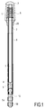
- the antenna shown in Figure 1 has the appearance of a rod and comprises a light source 9, and a light pipe 3.
- This pipe is for example a solid tube made of transparent plastic, for example example in methacrylate.
- the upper end of the conduit 3 is placed opposite a head here consisting of an assembly comprising a cabochon 7 and a sleeve 1, both in translucent or opalescent material, which refer to outside the light transmitted by the conduit.
- the signal receiving elements consist of a part helical electric formed by a metal spring 6, which surrounds the light pipe.
- a sheath 2 made of electrically material conductor, is connected to the electrical part 6 of the antenna and provides electrical connection with a circuit of a radiocommunication receiver, by example a mobile phone.
- This sheath includes a threaded part 20 which allows the antenna to be screwed into the phone.
- the light source is an encapsulated light emitting diode in a housing 9.
- This housing 9 is placed opposite the light pipe, although heard with a light emitting surface facing the duct. he is fixed to a support pin 10, itself fixed to the antenna by means a body 8 in the form of a tube which surrounds and protects the light pipe and holds pin 10.
- Connection rings 5A, 5B surround pin 10 completely and are each connected to one of the electrodes of the diode. They allow, when the antenna is put in place by screwing in the receiver, electrical contact with electrical conductors of the receiver whatever the rotational position of the tube 8.
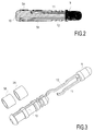
- the element which includes the diode and its contacts is shown more in detail in Figures 2 and 3.
- the diode 9, for example in a housing standard type SOD53F, has two connections 11 and 12, which are formed with a curved part at their end, on the left in the figures.
- the body 10 comprises two longitudinal grooves for receiving the connections 11 and 12.
- the two rings 5A and 5B are in electrical contact respectively with the curved part of the connection 11 and of the connection 12.
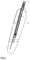
- the radiocommunication transceiver shown in Figure 4 here a mobile phone, includes a removable antenna 13, with a outer end 17 provided with means for emitting light and signal receiving elements provided with a signal conducting part radio 2. At the other end of the antenna is mounted a diode light emitting 9 whose electrical connections are connected to connection rings 5A, 5B.
- Telephone includes electrical circuit produced on a printed circuit 30 to which are connected, on the one hand, a contact signal 14, here a ring pierced with a threaded hole to screw the part 20 (Figure 1) of the antenna, that is to say the part connected to the elements of signal reception and, on the other hand, lighting contacts 15, 16 which are brought into contact with the contacts 5A, 5B of the diode when, as this is the case here, the antenna is installed in the receiver.
- a contact signal 14 here a ring pierced with a threaded hole to screw the part 20 ( Figure 1) of the antenna, that is to say the part connected to the elements of signal reception and, on the other hand, lighting contacts 15, 16 which are brought into contact with the contacts 5A, 5B of the diode when, as this is the case here, the antenna is installed in the receiver.
Landscapes
- Engineering & Computer Science (AREA)
- Computer Networks & Wireless Communication (AREA)
- Support Of Aerials (AREA)
- Details Of Aerials (AREA)
- Telephone Function (AREA)
Abstract
Description
La présente invention concerne une antenne destinée à un émetteur et/ou récepteur de radiocommunication, antenne ayant l'apparence d'une tige et comprenant une source de lumière, un conduit de lumière, et une partie diffusant la lumière.The present invention relates to an antenna intended for a transmitter and / or radio receiver, antenna having the appearance of a rod and comprising a light source, a light pipe, and a part diffusing the light.
Elle concerne également un émetteur et/ou récepteur de radiocommunication destiné à être équipé d'une antenne.It also relates to a transmitter and / or receiver of radio communication intended to be equipped with an antenna.
Une antenne selon le préambule ci-dessus est connue du document EP 98 200 315.4. Selon ce document, une antenne en forme de tige est munie d'une source de lumière, et comprend un conduit de lumière et une partie diffusant la lumière, la source de lumière étant située à l'extérieur de l'antenne.An antenna according to the preamble above is known from the document EP 98 200 315.4. According to this document, a rod-shaped antenna is provided with a light source, and comprises a light pipe and a light diffusing part, the light source being located outside of the antenna.
Un objet de l'invention est de faciliter le montage de l'antenne, notamment lorsque cette dernière est vendue comme accessoire à monter par l'utilisateur.An object of the invention is to facilitate the mounting of the antenna, especially when the latter is sold as a fitting accessory by the user.
A cet effet, la source de lumière est une diode électroluminescente encapsulée dans un boítier et munie de connexions, ce boítier est fixé à l'antenne en face du conduit de lumière, et les connexions de la diode sont disposées de façon à permettre, lorsque l'antenne est mise en place dans le récepteur, un contact électrique avec des conducteurs électriques du récepteur.For this purpose, the light source is a light emitting diode encapsulated in a box and provided with connections, this box is fixed to the antenna in front of the light pipe, and the diode connections are arranged so as to allow, when the antenna is placed in the receiver, electrical contact with electrical conductors of the receiver.
Un récepteur et/ou émetteur de radiocommunication selon l'invention comprend d'une part des contacts de signal destinés à être mis en contact avec des éléments de réception de signal de l'antenne, et d'autre part des contacts d'éclairage destinés à être mis en contact avec les contacts de la diode, lorsque l'antenne est mise en place dans le récepteur.A radiocommunication receiver and / or transmitter according to the invention comprises on the one hand signal contacts intended to be brought into contact with antenna signal receiving elements, and secondly lighting contacts intended to be brought into contact with the contacts of the diode, when the antenna is placed in the receiver.
Un appareil équipé d'une antenne ordinaire non lumineuse peut donc être muni, pour un coût marginal très faible, de contacts pour une antenne lumineuse, permettant l'installation d'une telle antenne en option et par l'utilisateur lui-même.A device equipped with an ordinary non-luminous antenna can therefore be provided, for a very low marginal cost, with contacts for an antenna luminous, allowing the installation of such an optional antenna and by the user himself.
Des modes particuliers de réalisation de l'invention apparaissent dans
les revendications dépendantes 2 à 4.Particular embodiments of the invention appear in
Ces aspects de l'invention ainsi que d'autres aspects plus détaillés
apparaítront plus clairement grâce à la description suivante d'un mode de
réalisation constituant un exemple non limitatif.
L'antenne représentée sur la figure 1 a l'apparence d'une tige et
comprend une source de lumière 9, et un conduit de lumière 3. Ce conduit
est par exemple un tube plein en matière plastique transparente, par
exemple en méthacrylate.The antenna shown in Figure 1 has the appearance of a rod and
comprises a
L'extrémité supérieure du conduit 3 est placée en regard d'une tête
constituée ici d'un ensemble comprenant un cabochon 7 et un manchon 1,
tous deux en matériau translucide ou opalescent, qui renvoient vers
l'extérieur la lumière transmise par le conduit. A l'intérieur du manchon 1,
les éléments de réception de signal sont constitués par une partie
électrique hélicoïdale formée d'un ressort métallique 6, qui entoure le
conduit de lumière. Une gaine 2, réalisée en matériau électriquement
conducteur, est reliée à la partie électrique 6 de l'antenne et assure une
liaison électrique avec un circuit d'un récepteur de radiocommunication, par
exemple un téléphone mobile. Cette gaine comprend une partie 20 filetée
qui permet la fixation par vissage de l'antenne dans le téléphone.The upper end of the
La source de lumière est une diode électroluminescente encapsulée
dans un boítier 9. Ce boítier 9 est placé en face du conduit de lumière, bien
entendu avec une surface émettrice de lumière tournée vers le conduit. Il
est fixé à une broche support 10, elle même fixée à l'antenne au moyen
d'un corps 8 en forme de tube qui entoure et protège le conduit de lumière
et maintient la broche 10. Des bagues de connexion 5A, 5B entourent
complètement la broche 10 et sont reliés chacun à une des électrodes de la
diode. Elles permettent, lorsque l'antenne est mise en place par vissage
dans le récepteur, un contact électrique avec des conducteurs électriques
du récepteur quelle que soit la position en rotation du tube 8.The light source is an encapsulated light emitting diode
in a
L'élément qui comprend la diode et ses contacts est représenté plus
en détail par les figures 2 et 3. La diode 9, par exemple dans un boítier
normalisé de type SOD53F, comporte deux connexions 11 et 12, qui sont
formées avec une partie cintrée à leur extrémité, à gauche sur les figures.
Le corps 10 comprend deux rainures longitudinales pour recevoir les
connexions 11 et 12. Les deux bagues 5A et 5B sont en contact électrique
respectivement avec la partie cintrée de la connexion 11 et de la connexion
12.The element which includes the diode and its contacts is shown more
in detail in Figures 2 and 3. The
L'émetteur récepteur de radiocommunication représenté à la figure 4,
ici un téléphone mobile, comprend une antenne amovible 13, avec une
extrémité 17 externe munie de moyens pour émettre de la lumière et
d'éléments de réception de signal munis d'une partie conductrice de signal
radio 2. A l'autre extrémité de l'antenne est montée une diode
électroluminescente 9 dont les connexions électriques sont reliées à des
bagues de connexion 5A, 5B. Le téléphone comprend un circuit électrique
réalisé sur un circuit imprimé 30 auquel sont reliés, d'une part, un contact
de signal 14, ici une bague percée d'un trou fileté pour y visser la partie 20
(figure 1) de l'antenne, c'est-à-dire la partie reliée aux éléments de
réception de signal et, d'autre part, des contacts d'éclairage 15, 16 qui
sont mis en contact avec les contacts 5A, 5B de la diode lorsque, comme
c'est le cas ici, l'antenne est mise en place dans le récepteur.The radiocommunication transceiver shown in Figure 4,
here a mobile phone, includes a
Claims (5)
Applications Claiming Priority (2)
| Application Number | Priority Date | Filing Date | Title |
|---|---|---|---|
| FR9814412 | 1998-11-17 | ||
| FR9814412 | 1998-11-17 |
Publications (1)
| Publication Number | Publication Date |
|---|---|
| EP1003237A1 true EP1003237A1 (en) | 2000-05-24 |
Family
ID=9532811
Family Applications (1)
| Application Number | Title | Priority Date | Filing Date |
|---|---|---|---|
| EP99203699A Withdrawn EP1003237A1 (en) | 1998-11-17 | 1999-11-08 | Antenna used in a transceiver |
Country Status (6)
| Country | Link |
|---|---|
| US (1) | US6262686B1 (en) |
| EP (1) | EP1003237A1 (en) |
| JP (1) | JP2000196319A (en) |
| KR (1) | KR100695808B1 (en) |
| CN (1) | CN1149707C (en) |
| TW (1) | TW439320B (en) |
Cited By (1)
| Publication number | Priority date | Publication date | Assignee | Title |
|---|---|---|---|---|
| WO2002025766A1 (en) * | 2000-09-18 | 2002-03-28 | Siemens Aktiengesellschaft | Illuminable antenna |
Families Citing this family (13)
| Publication number | Priority date | Publication date | Assignee | Title |
|---|---|---|---|---|
| US7463863B1 (en) * | 1997-08-08 | 2008-12-09 | Agere Systems, Inc. | Wireless terminal adapted for detachably connecting with a radio |
| US6658273B1 (en) * | 2000-06-02 | 2003-12-02 | Jeff D. Sharp | Cordless light system |
| US7031667B2 (en) * | 2000-08-25 | 2006-04-18 | Nec Corporation | Portable telephone |
| US6490439B1 (en) * | 2000-10-04 | 2002-12-03 | 3Com Corporation | Lighted antenna for transceiver device |
| US20020155855A1 (en) * | 2001-04-20 | 2002-10-24 | Yung-Tang Lee | Conversation timer for mobile phone |
| US7867095B2 (en) * | 2005-06-17 | 2011-01-11 | Igt | Candle radio |
| KR101536171B1 (en) * | 2009-02-27 | 2015-07-13 | 주식회사 케이엠더블유 | Antenna with function of lighting for mobile communication system |
| DE102012219404A1 (en) * | 2012-10-24 | 2014-04-24 | Bayerische Motoren Werke Aktiengesellschaft | motor vehicle |
| CN105206929B (en) * | 2015-09-02 | 2019-06-11 | 深圳市元征软件开发有限公司 | The antenna of automotive diagnostic system and the communication device of automotive diagnostic system |
| US10476126B2 (en) * | 2015-10-30 | 2019-11-12 | Lutron Technology Company Llc | Wireless control device having an antenna illuminated with visible light |
| JP7102399B2 (en) * | 2016-09-19 | 2022-07-19 | シグニファイ ホールディング ビー ヴィ | Lighting device with communication elements for wireless communication |
| US10755536B2 (en) * | 2019-01-16 | 2020-08-25 | Dell Products, Lp | System and method for manufacture of a light reflecting antenna system |
| JP6798073B2 (en) * | 2019-06-04 | 2020-12-09 | エスゼット ディージェイアイ テクノロジー カンパニー リミテッドSz Dji Technology Co.,Ltd | Mobile body and sensor unit |
Citations (5)
| Publication number | Priority date | Publication date | Assignee | Title |
|---|---|---|---|---|
| JPS60144002A (en) * | 1984-01-06 | 1985-07-30 | Matsushita Electric Ind Co Ltd | Antenna device |
| JPH09246823A (en) * | 1996-03-07 | 1997-09-19 | Harada Ind Co Ltd | Antenna mounted with light emitting body |
| JPH09298410A (en) * | 1996-05-07 | 1997-11-18 | Maki Kinzoku:Kk | Led light emitting device |
| DE29720031U1 (en) * | 1997-11-12 | 1998-01-15 | Wolfrum, Werner, 95490 Mistelgau | Transmitting and receiving antenna for transmitting and / or receiving signals of a certain frequency from a transponder |
| EP0865098A1 (en) * | 1997-02-14 | 1998-09-16 | Koninklijke Philips Electronics N.V. | Lighting antenna and radio communication device with such an antenna |
Family Cites Families (5)
| Publication number | Priority date | Publication date | Assignee | Title |
|---|---|---|---|---|
| US2473981A (en) * | 1946-01-21 | 1949-06-21 | Francis G Wood | Illuminated radio antenna |
| JP3515797B2 (en) * | 1993-10-08 | 2004-04-05 | 株式会社リコー | Helical antenna |
| JPH09167907A (en) * | 1995-12-14 | 1997-06-24 | Casio Comput Co Ltd | Antenna system |
| KR19990047842A (en) * | 1997-12-05 | 1999-07-05 | 윤종용 | Antenna device of portable terminal |
| US6002378A (en) * | 1997-12-19 | 1999-12-14 | Harada Industry Co., Ltd. | Telescopic rod antenna apparatus |
-
1999
- 1999-11-08 EP EP99203699A patent/EP1003237A1/en not_active Withdrawn
- 1999-11-12 CN CNB991243269A patent/CN1149707C/en not_active Expired - Fee Related
- 1999-11-12 US US09/439,200 patent/US6262686B1/en not_active Expired - Fee Related
- 1999-11-15 JP JP11324443A patent/JP2000196319A/en not_active Withdrawn
- 1999-11-17 KR KR1019990051185A patent/KR100695808B1/en not_active IP Right Cessation
- 1999-12-14 TW TW088121886A patent/TW439320B/en not_active IP Right Cessation
Patent Citations (6)
| Publication number | Priority date | Publication date | Assignee | Title |
|---|---|---|---|---|
| JPS60144002A (en) * | 1984-01-06 | 1985-07-30 | Matsushita Electric Ind Co Ltd | Antenna device |
| JPH09246823A (en) * | 1996-03-07 | 1997-09-19 | Harada Ind Co Ltd | Antenna mounted with light emitting body |
| US5917453A (en) * | 1996-03-07 | 1999-06-29 | Harada Industry Co., Ltd. | Illuminant-mounted antenna |
| JPH09298410A (en) * | 1996-05-07 | 1997-11-18 | Maki Kinzoku:Kk | Led light emitting device |
| EP0865098A1 (en) * | 1997-02-14 | 1998-09-16 | Koninklijke Philips Electronics N.V. | Lighting antenna and radio communication device with such an antenna |
| DE29720031U1 (en) * | 1997-11-12 | 1998-01-15 | Wolfrum, Werner, 95490 Mistelgau | Transmitting and receiving antenna for transmitting and / or receiving signals of a certain frequency from a transponder |
Non-Patent Citations (3)
| Title |
|---|
| PATENT ABSTRACTS OF JAPAN vol. 009, no. 305 (E - 363) 3 December 1985 (1985-12-03) * |
| PATENT ABSTRACTS OF JAPAN vol. 098, no. 001 30 January 1998 (1998-01-30) * |
| PATENT ABSTRACTS OF JAPAN vol. 098, no. 003 27 February 1998 (1998-02-27) * |
Cited By (1)
| Publication number | Priority date | Publication date | Assignee | Title |
|---|---|---|---|---|
| WO2002025766A1 (en) * | 2000-09-18 | 2002-03-28 | Siemens Aktiengesellschaft | Illuminable antenna |
Also Published As
| Publication number | Publication date |
|---|---|
| KR100695808B1 (en) | 2007-03-15 |
| CN1256524A (en) | 2000-06-14 |
| KR20000035538A (en) | 2000-06-26 |
| US6262686B1 (en) | 2001-07-17 |
| JP2000196319A (en) | 2000-07-14 |
| TW439320B (en) | 2001-06-07 |
| CN1149707C (en) | 2004-05-12 |
Similar Documents
| Publication | Publication Date | Title |
|---|---|---|
| EP1003237A1 (en) | Antenna used in a transceiver | |
| FR2793955A1 (en) | DEVICE FOR ELECTRICALLY CONNECTING A COAXIAL LINE TO A PRINTED CIRCUIT BOARD | |
| FR2924277A1 (en) | SHIELD CONNECTOR AGAINST ELECTROMAGNETIC WAVES | |
| EP3860737B1 (en) | Accessory of light-sabre type | |
| EP0678223B1 (en) | High frequency coaxial-type connector-switch component | |
| FR2919424A1 (en) | Electrical receiver protecting and supplying device for electrical installation, has case comprising fixation units fixed on any portion of main insulated feeder conductor, and electrical connection units connected at conductor | |
| FR2707429A1 (en) | Connection accessory. | |
| EP0707330B1 (en) | Load break switch | |
| EP1672740B1 (en) | Rapid connection terminal for switches and outlet sockets | |
| CA2105312A1 (en) | Very low voltage mecanical and electrical installation coupling device | |
| EP0638763B1 (en) | Indicator lamp | |
| US5955999A (en) | Antenna assembly for a radiotelephone | |
| EP0680109B1 (en) | Antenna base with a lock nut on a support with unidirectional mounting means | |
| FR2745964A1 (en) | Portable RF transceiver apparatus e.g. for remote control of electrical equipment | |
| FR2982408A1 (en) | ELECTRICAL CONDUCTOR TEAM | |
| FR2895785A1 (en) | LUMINOUS DEVICE FOR SIGNALING PANELS | |
| FR2597609A1 (en) | PORTABLE AND AUTONOMOUS LASER TRANSMITTER | |
| EP0611899B1 (en) | Device for detecting wear of friction lining | |
| FR2729010A1 (en) | ANTENNA FOR A MOTOR VEHICLE CAPABLE OF RECEIVING AN ACTIVE IMPEDANCE ADAPTER AND ASSEMBLY ACTIVE IMPEDANCE ADAPTER FOR SUCH ANTENNA | |
| WO2000062383A1 (en) | Tubular casing for laser beam emitter | |
| FR2761792A1 (en) | LIGHT EMITTING DIODE SIGNALING DEVICE | |
| EP0949722A1 (en) | Low voltage electrical connector | |
| FR2685980A1 (en) | Connection device, especially for bicycle lighting | |
| FR2630063A1 (en) | Static-electricity diffusing device mounted on a motor vehicle | |
| FR2732519A1 (en) | Electrical connector with enhanced insulation and protection against water or dust |
Legal Events
| Date | Code | Title | Description |
|---|---|---|---|
| PUAI | Public reference made under article 153(3) epc to a published international application that has entered the european phase |
Free format text: ORIGINAL CODE: 0009012 |
|
| AK | Designated contracting states |
Kind code of ref document: A1 Designated state(s): DE FR GB IT |
|
| AX | Request for extension of the european patent |
Free format text: AL;LT;LV;MK;RO;SI |
|
| 17P | Request for examination filed |
Effective date: 20001124 |
|
| AKX | Designation fees paid |
Free format text: DE FR GB IT |
|
| 17Q | First examination report despatched |
Effective date: 20061222 |
|
| RAP1 | Party data changed (applicant data changed or rights of an application transferred) |
Owner name: SHENZHEN SANG FEI CONSUMER COMMUNICATIONS CO., LTD |
|
| STAA | Information on the status of an ep patent application or granted ep patent |
Free format text: STATUS: THE APPLICATION IS DEEMED TO BE WITHDRAWN |
|
| 18D | Application deemed to be withdrawn |
Effective date: 20090603 |